EP1166717B1 - Messgerät zur Messung der elastischen Eigenschaften einer Oberflächenstruktur - Google Patents
Messgerät zur Messung der elastischen Eigenschaften einer Oberflächenstruktur Download PDFInfo
- Publication number
- EP1166717B1 EP1166717B1 EP00113235A EP00113235A EP1166717B1 EP 1166717 B1 EP1166717 B1 EP 1166717B1 EP 00113235 A EP00113235 A EP 00113235A EP 00113235 A EP00113235 A EP 00113235A EP 1166717 B1 EP1166717 B1 EP 1166717B1
- Authority
- EP
- European Patent Office
- Prior art keywords
- measuring
- measuring device
- probe
- surface structure
- bimorph
- Prior art date
- Legal status (The legal status is an assumption and is not a legal conclusion. Google has not performed a legal analysis and makes no representation as to the accuracy of the status listed.)
- Expired - Lifetime
Links
- 239000000523 sample Substances 0.000 claims description 29
- 238000005259 measurement Methods 0.000 claims description 20
- 238000011156 evaluation Methods 0.000 claims description 6
- 230000001960 triggered effect Effects 0.000 claims description 5
- 239000000463 material Substances 0.000 description 4
- 238000005452 bending Methods 0.000 description 3
- 238000011282 treatment Methods 0.000 description 3
- 239000004425 Makrolon Substances 0.000 description 2
- 238000004026 adhesive bonding Methods 0.000 description 2
- 239000002313 adhesive film Substances 0.000 description 2
- 230000005540 biological transmission Effects 0.000 description 2
- 238000006073 displacement reaction Methods 0.000 description 2
- 238000011835 investigation Methods 0.000 description 2
- 229920000515 polycarbonate Polymers 0.000 description 2
- 102000008186 Collagen Human genes 0.000 description 1
- 108010035532 Collagen Proteins 0.000 description 1
- 102000016942 Elastin Human genes 0.000 description 1
- 108010014258 Elastin Proteins 0.000 description 1
- 235000021152 breakfast Nutrition 0.000 description 1
- 210000000481 breast Anatomy 0.000 description 1
- 229910010293 ceramic material Inorganic materials 0.000 description 1
- 229920001436 collagen Polymers 0.000 description 1
- 230000000052 comparative effect Effects 0.000 description 1
- 230000006835 compression Effects 0.000 description 1
- 238000007906 compression Methods 0.000 description 1
- 239000002537 cosmetic Substances 0.000 description 1
- 230000003111 delayed effect Effects 0.000 description 1
- 238000011161 development Methods 0.000 description 1
- 239000003814 drug Substances 0.000 description 1
- 230000000694 effects Effects 0.000 description 1
- 229920002549 elastin Polymers 0.000 description 1
- 239000000835 fiber Substances 0.000 description 1
- 238000004519 manufacturing process Methods 0.000 description 1
- 239000003550 marker Substances 0.000 description 1
- 231100000241 scar Toxicity 0.000 description 1
- 230000035939 shock Effects 0.000 description 1
- 239000000725 suspension Substances 0.000 description 1
- 238000004154 testing of material Methods 0.000 description 1
- 238000012546 transfer Methods 0.000 description 1
Images

Classifications
-
- A—HUMAN NECESSITIES
- A61—MEDICAL OR VETERINARY SCIENCE; HYGIENE
- A61B—DIAGNOSIS; SURGERY; IDENTIFICATION
- A61B5/00—Measuring for diagnostic purposes; Identification of persons
- A61B5/68—Arrangements of detecting, measuring or recording means, e.g. sensors, in relation to patient
- A61B5/6801—Arrangements of detecting, measuring or recording means, e.g. sensors, in relation to patient specially adapted to be attached to or worn on the body surface
- A61B5/683—Means for maintaining contact with the body
- A61B5/6832—Means for maintaining contact with the body using adhesives
- A61B5/6833—Adhesive patches
-
- A—HUMAN NECESSITIES
- A61—MEDICAL OR VETERINARY SCIENCE; HYGIENE
- A61B—DIAGNOSIS; SURGERY; IDENTIFICATION
- A61B5/00—Measuring for diagnostic purposes; Identification of persons
- A61B5/0048—Detecting, measuring or recording by applying mechanical forces or stimuli
- A61B5/0051—Detecting, measuring or recording by applying mechanical forces or stimuli by applying vibrations
-
- A—HUMAN NECESSITIES
- A61—MEDICAL OR VETERINARY SCIENCE; HYGIENE
- A61B—DIAGNOSIS; SURGERY; IDENTIFICATION
- A61B5/00—Measuring for diagnostic purposes; Identification of persons
- A61B5/0048—Detecting, measuring or recording by applying mechanical forces or stimuli
- A61B5/0053—Detecting, measuring or recording by applying mechanical forces or stimuli by applying pressure, e.g. compression, indentation, palpation, grasping, gauging
-
- A—HUMAN NECESSITIES
- A61—MEDICAL OR VETERINARY SCIENCE; HYGIENE
- A61B—DIAGNOSIS; SURGERY; IDENTIFICATION
- A61B5/00—Measuring for diagnostic purposes; Identification of persons
- A61B5/44—Detecting, measuring or recording for evaluating the integumentary system, e.g. skin, hair or nails
- A61B5/441—Skin evaluation, e.g. for skin disorder diagnosis
- A61B5/442—Evaluating skin mechanical properties, e.g. elasticity, hardness, texture, wrinkle assessment
-
- G—PHYSICS
- G01—MEASURING; TESTING
- G01N—INVESTIGATING OR ANALYSING MATERIALS BY DETERMINING THEIR CHEMICAL OR PHYSICAL PROPERTIES
- G01N29/00—Investigating or analysing materials by the use of ultrasonic, sonic or infrasonic waves; Visualisation of the interior of objects by transmitting ultrasonic or sonic waves through the object
- G01N29/22—Details, e.g. general constructional or apparatus details
- G01N29/221—Arrangements for directing or focusing the acoustical waves
-
- G—PHYSICS
- G01—MEASURING; TESTING
- G01N—INVESTIGATING OR ANALYSING MATERIALS BY DETERMINING THEIR CHEMICAL OR PHYSICAL PROPERTIES
- G01N2291/00—Indexing codes associated with group G01N29/00
- G01N2291/01—Indexing codes associated with the measuring variable
- G01N2291/014—Resonance or resonant frequency
-
- G—PHYSICS
- G01—MEASURING; TESTING
- G01N—INVESTIGATING OR ANALYSING MATERIALS BY DETERMINING THEIR CHEMICAL OR PHYSICAL PROPERTIES
- G01N2291/00—Indexing codes associated with group G01N29/00
- G01N2291/02—Indexing codes associated with the analysed material
- G01N2291/024—Mixtures
- G01N2291/02483—Other human or animal parts, e.g. bones
-
- G—PHYSICS
- G01—MEASURING; TESTING
- G01N—INVESTIGATING OR ANALYSING MATERIALS BY DETERMINING THEIR CHEMICAL OR PHYSICAL PROPERTIES
- G01N2291/00—Indexing codes associated with group G01N29/00
- G01N2291/02—Indexing codes associated with the analysed material
- G01N2291/028—Material parameters
- G01N2291/02872—Pressure
-
- G—PHYSICS
- G01—MEASURING; TESTING
- G01N—INVESTIGATING OR ANALYSING MATERIALS BY DETERMINING THEIR CHEMICAL OR PHYSICAL PROPERTIES
- G01N2291/00—Indexing codes associated with group G01N29/00
- G01N2291/10—Number of transducers
- G01N2291/103—Number of transducers one emitter, two or more receivers
-
- G—PHYSICS
- G01—MEASURING; TESTING
- G01N—INVESTIGATING OR ANALYSING MATERIALS BY DETERMINING THEIR CHEMICAL OR PHYSICAL PROPERTIES
- G01N2291/00—Indexing codes associated with group G01N29/00
- G01N2291/26—Scanned objects
- G01N2291/263—Surfaces
- G01N2291/2632—Surfaces flat
Definitions
- the invention relates to a measuring device for measuring the elastic properties a surface structure according to the preamble of claim 1.
- a Measuring device is known from EP 0 329 817.
- the known device has an in a housing axially movably mounted probe on the measuring tips with a predetermined contact pressure orthogonal to the skin surface of a biological body can be placed.
- the measuring tips transmit sound pulses of bimorph piezoelectric transducers in the skin surface, using a measuring tip as Sender works and the other two as receiver.
- the receivers measure the length of time between transmission and reception of the acoustic pulse, which runs through the skin between the measuring tips. From the time measurement is determines the propagation velocity of the sound wave in the skin.
- the flat and strip-shaped bimorph piezoelectric transducers consist of one provided with electrodes ceramic material which has a low Having breaking strength.
- the bimorph elements are therefore very brittle and break fast under mechanical load.
- the invention is based on the object, a measuring device of the aforementioned To create kind, which has a higher operational safety and insensitive against shocks.
- the invention advantageously provides that the measuring tips of the Holder for the bimorph elements are formed, wherein the strip-shaped bimorph elements only one-sidedly attached to the holder with one end are.
- the holders for the bimorph elements themselves Forming tip, the bimorph elements are advantageously none subjected to mechanical stress, so that they are also inappropriate Do not break treatment or high impact load.
- the bimorph elements are at the measuring tips attached facing the end of the bracket.
- the holder allows the Transmission of sound pulses via the measuring tips on the Surface structure and at the same time protects the bimorph element Damage.
- the stripe-shaped bimorph elements are each on one Holder at its free end facing the surface structure, preferably attached by gluing, thereby producing the generated sound pulses optimally transferred to the free, the measuring tip forming end of the bracket can.
- each strip-shaped bimorph element At the free end of each strip-shaped bimorph element is respectively a seismic mass, preferably fixed by gluing. Bends that bimorph element of the transmitter due to an electrical pulse is the Bending moment as sound pulse over the measuring tip on the surface structure transfer.
- the seismic mass serves as a support for this bending moment with their inertia.
- the mass inertia of the seismic mass causes that the arrangement is very sensitive to fast pulses, but hardly to relative slow movements caused by improper treatment, responding.
- the holders a bimorph Have elements adapted elongated recess, in which the bimorphs Can swing elements freely.
- the recess allows the parallel to the mounts extending bimorph elements in their orthogonal to the Brackets swinging vibration through the recess swing through can.
- the brackets consist of two flat, strip-shaped parts, which are attached to the The opposite ends of the measuring probes with a parallel distance from each other attached to a common carrier.
- the brackets are very flexible, so that the sound pulses of the transmitter are not transmitted to the carrier. Makrolon is used as the preferred material for the brackets.
- the Flexibility of the holder prevents the sound pulse on the Suspension is transmitted to the receiver.
- the probe is mounted axially movable in the housing and the measuring tips can be under a defined spring tension against the skin surface be created.
- the sound pulse and the measurement can be triggered when the probe has traveled a predetermined path. This ensures that the Measuring tips always with the same contact pressure against the surface structure are created.
- the sound impulse and the measurement can also after a predetermined Time delay be triggered, and this in combination with the Replacing a specific probe path is possible.
- the evaluation device can receive the data recorded by the receiver Measuring signals by means of a resonance measurement in the frequency range between 0 and evaluate 10 kHz.
- the probe on the has to be examined surface structure fixable guide part, in which the probe is guided orthogonal to the surface structure and in which the probe with the help of markings on the probe and on the guide part can take different defined angular positions.
- the leadership part for example, consists of a cylindrical sleeve, which on the surface is glued on, the probe picks up that an orthogonal orientation of the probe relative to the surface structure is guaranteed.
- Angled markings attached to it in conjunction with a marker allow the probe to rotate the probe by predetermined angles, so that Measurements relative to a starting position at an angle of For example, 0 °, 45 °, 90 ° or 135 ° are possible.
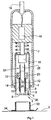
- the measuring device shown in Fig. 1 consists of a housing 1 in which axially movably a probe 2 is arranged.
- the probe 2 consists of a housing 5, in which on a carrier 28 with a parallel distance from each other two flat, strip-shaped longitudinally extending brackets 8, 10 are attached, the each record a bimorph element 12, 14.
- the holders 8, 10 consist of Makrolon and have a high flexibility.
- the brackets 8, 10 are only one side attached to the carrier 28 and can with their free Swing ends free.
- the bimorph element 12 extends in a strip parallel to the Holder 8 and is preferably in the region of the measuring tip 4 on the outside bonded.
- the free, remote from the measuring tip 4 end of the bimorph Element 12 carries a seismic mass 20, which is preferably glued.
- One of a controller 16 with a power electronics bimorph Element 12 supplied electrical pulse generates a bending moment in the bimorph element and transmits a sound pulse on the measuring tip 4.
- the seismic mass 20 serves as moment support.
- the inertia of the Mass 20 causes the arrangement to be very sensitive to fast pulses, on the other hand hardly sensitive to relatively slow movements by improper handling of the meter arise, reacts.
- the bimorph element 12 forms with the measuring tip 4 and the seismic mass 20 a transmitter for sound pulses.
- Mirrored to the Longitudinal axis of the measuring device by the carrier 28 is a receiver, from the measuring tip 6, the holder 10, the bimorph element 14 and the seismic mass 22 is formed.
- the brackets 8, 10 have, as best From Fig. 2 it can be seen, a recess 24, 26, which is a free swing the bimorph elements 12, 14 and the seismic masses 20, 22 in one orthogonal to the brackets 8, 10 extending direction allows.
- the housing 5 and the measuring probe 2 are within the housing 1 with the help biased a compression spring 7.
- An evaluation device 18 analyzes the recorded from the measuring tip 6 Measuring signals, for example by means of a resonance measurement in the frequency domain between 0 and 10 kHz.
- the results of the measurements can be viewed on a display in the Drawings not shown, which are connected to the Evaluation device 18 is connected via a cable 19.
- a hollow cylindrical guide part 32 may be the distal end of the probe 2 receive, so that the measuring tips 4, 6 exactly orthogonal to the skin surface. 3 aligned during the measurement.
- the guide part 32 has a flange on, on its the surface structure 3 side facing a replaceable, substantially annular double-adhesive film 34 carries. With Help the double-adhesive film 34, the guide member 32 at one to be fixed in the investigating body of the surface structure 3.
- annular flange 35 on his Circumference two holes 40 which serve on the surface structure 3, for example, with a pen Apply color markings to the measurement at the same place with the same Orientation of the probe 2 to perform at longer intervals too can.
- annular flange carries markings 36 which are predetermined Angular distance from each other.
- markings 36 which are predetermined Angular distance from each other.
- Figure 1 can be the Measuring device reproducible at the same measuring point and in the same Arrange angular position on the surface structure 3.
- the evaluation device 18 is also in the Able to save readings for later comparison.
- the measurement can be triggered when the measuring tips 4, 6 under a certain bias against the skin surface 3 are pressed.
- the height the bias voltage for example, via a displacement measurement of the probe. 2 be found that the axial displacement of the probe 2 against the spring force measures.
- the triggering of the sound pulse and the measurement can be timed be delayed.
- the sound pulses used are in the range between 0.5 and 30 kHz.
- the measured values are representative of the elastic properties of the Surface structure 3, in which also different elasticity values for the Transverse and longitudinal elasticity can be determined.
- the surface structure 3 may be made of elastically vibratory materials whose viscoelastic properties can be investigated.
- the Meter can also be used for material testing at different Materials or for production control, such as rubbery or leathery materials.
Landscapes
- Health & Medical Sciences (AREA)
- Life Sciences & Earth Sciences (AREA)
- Physics & Mathematics (AREA)
- General Health & Medical Sciences (AREA)
- Pathology (AREA)
- Biomedical Technology (AREA)
- Engineering & Computer Science (AREA)
- Heart & Thoracic Surgery (AREA)
- Medical Informatics (AREA)
- Molecular Biology (AREA)
- Surgery (AREA)
- Animal Behavior & Ethology (AREA)
- Biophysics (AREA)
- Public Health (AREA)
- Veterinary Medicine (AREA)
- Acoustics & Sound (AREA)
- Dermatology (AREA)
- Chemical & Material Sciences (AREA)
- Analytical Chemistry (AREA)
- Biochemistry (AREA)
- General Physics & Mathematics (AREA)
- Immunology (AREA)
- Measuring And Recording Apparatus For Diagnosis (AREA)
- Investigating Or Analyzing Materials By The Use Of Ultrasonic Waves (AREA)
- Investigating Strength Of Materials By Application Of Mechanical Stress (AREA)
- Measurement Of The Respiration, Hearing Ability, Form, And Blood Characteristics Of Living Organisms (AREA)
Description
- Fig. 1
- ein Querschnitt durch das Messgerät,
- Fig. 2
- eine Draufsicht auf eine Halterung mit einem bimorphen Element, und
- Fig. 3
- eine Draufsicht auf ein Führungsteil für die Sonde.
Claims (11)
- Messgerät zur Messung der elastischen Eigenschaften einer Oberflächenstruktur (3) mit einer in einem Gehäuse (1) angeordneten Sonde (2), mit einem Sender und mindestens einem Empfänger, wobei von dem Sender Schallimpulse emittiert und von dem Empfänger das Ausbreitungsverhalten der Schallimpulse in der Oberflächenstruktur (3) erfasst werden, mit einer Steuereinrichtung (16) für die Schallimpulserzeugung und mit einer Auswerteeinrichtung (18) für die von dem Empfänger aufgenommenen Messsignale, wobei mindestens zwei nebeneinander angeordnete auf die Oberflächenstruktur (3) aufsetzbare Messspitzen (4,6) mit von einer Halterung (8,10) getragenen streifenförmigen bimorphen Elementen (12,14) als Sende- und Empfangselemente verbunden sind,
dadurch gekennzeichnet, dass die Messspitzen (4,6) von den Halterungen (8,10) für die bimorphen Elemente (12,14) gebildet sind und dass die streifenförmigen bimorphen Elemente (12,14) einseitig mit ihrem einen Ende an der Halterung (8,10) befestigt sind. - Messgerät nach Anspruch 1, dadurch gekennzeichnet, dass die bimorphen Elemente (12,14) an dem den Messspitzen (4,6) zugewandten Ende der Halterung (8,10) befestigt sind.
- Messgerät nach Anspruch 1 oder 2, dadurch gekennzeichnet, dass an dem freien Ende eines jeden streifenförmigen bimorphen Elementes (12,14) eine seismische Masse (20,22) befestigt ist.
- Messgerät nach einem der Ansprüche 1 bis 3, dadurch gekennzeichnet, dass die Halterungen (8,10) eine den bimorphen Elementen (12,14) angepasste längliche Aussparung (24,26) aufweisen, in der die bimorphen Elemente (12,14) frei schwingen können.
- Messgerät nach einem der Ansprüche 1 bis 4, dadurch gekennzeichnet, dass die Halterungen (8,10) aus zwei flachen streifenförmigen Teilen bestehen, die an dem den Messspitzen (4,6) gegenüberliegenden Ende (30) mit parallelem Abstand zueinander an einem gemeinsamen Träger (28) befestigt sind.
- Messgerät nach einem der Ansprüche 1 bis 5, dadurch gekennzeichnet, dass die Sonde (2) axial beweglich in dem Gehäuse (1) gelagert ist und die Messspitzen (4,6) unter Federspannung gegen die Oberflächen (3) anlegbar sind.
- Messgerät nach Anspruch 6, dadurch gekennzeichnet, dass der Schallimpuls und die Messung nach einem vorbestimmten Weg der Sonde (2) auslösbar sind.
- Messgerät nach Anspruch 6 oder 7, dadurch gekennzeichnet, dass der Schallimpuls und die Messung nach einer vorbestimmten Zeitverzögerung auslösbar sind.
- Messgerät nach einem der Ansprüche 1 bis 8, dadurch gekennzeichnet, dass der aus einem flachen bimorphen Element (12) bestehende Sender einen Einzelschallimpuls in die Oberflächenstruktur einkoppelt.
- Messgerät nach einem der Ansprüche 1 bis 9, dadurch gekennzeichnet, dass die Auswerteeinrichtung (18) die von dem Empfänger aufgenommenen Messsignale mit Hilfe einer Resonanzmessung im Frequenzbereich zwischen 0 und 10 kHz auswertet.
- Messgerät nach einem der Ansprüche 1 bis 10, dadurch gekennzeichnet, dass die Sonde (2) ein auf der Oberflächenstruktur (3) fixierbares Führungsteil(32) aufweist, in dem die Sonde (2) orthogonal zur Oberflächenstruktur (3) gehalten ist und in dem die Sonde (2) mit Hilfe von Markierungen (36,38) an der Sonde (2) und an dem Führungsteil (32) unterschiedliche Winkelstellungen einnehmen kann.
Priority Applications (4)
| Application Number | Priority Date | Filing Date | Title |
|---|---|---|---|
| DE50010517T DE50010517D1 (de) | 2000-06-21 | 2000-06-21 | Messgerät zur Messung der elastischen Eigenschaften einer Oberflächenstruktur |
| EP00113235A EP1166717B1 (de) | 2000-06-21 | 2000-06-21 | Messgerät zur Messung der elastischen Eigenschaften einer Oberflächenstruktur |
| JP2001186483A JP2002034930A (ja) | 2000-06-21 | 2001-06-20 | 表面構造の弾性特性を測定する測定装置 |
| US09/885,110 US6619423B2 (en) | 2000-06-21 | 2001-06-21 | Measuring device for measuring the elastic properties of a surface structure |
Applications Claiming Priority (1)
| Application Number | Priority Date | Filing Date | Title |
|---|---|---|---|
| EP00113235A EP1166717B1 (de) | 2000-06-21 | 2000-06-21 | Messgerät zur Messung der elastischen Eigenschaften einer Oberflächenstruktur |
Publications (2)
| Publication Number | Publication Date |
|---|---|
| EP1166717A1 EP1166717A1 (de) | 2002-01-02 |
| EP1166717B1 true EP1166717B1 (de) | 2005-06-08 |
Family
ID=8169043
Family Applications (1)
| Application Number | Title | Priority Date | Filing Date |
|---|---|---|---|
| EP00113235A Expired - Lifetime EP1166717B1 (de) | 2000-06-21 | 2000-06-21 | Messgerät zur Messung der elastischen Eigenschaften einer Oberflächenstruktur |
Country Status (4)
| Country | Link |
|---|---|
| US (1) | US6619423B2 (de) |
| EP (1) | EP1166717B1 (de) |
| JP (1) | JP2002034930A (de) |
| DE (1) | DE50010517D1 (de) |
Families Citing this family (22)
| Publication number | Priority date | Publication date | Assignee | Title |
|---|---|---|---|---|
| US20040106894A1 (en) * | 2002-09-06 | 2004-06-03 | Massachusetts Institute Of Technology | Needleless drug injection device |
| US20060052719A1 (en) * | 2004-09-09 | 2006-03-09 | Eduardo Ruvolo | Method of measuring of skin anisotropy |
| US20060163111A1 (en) * | 2004-12-23 | 2006-07-27 | Baril Daniel J | Device holder apparatus |
| US20090321457A1 (en) * | 2004-12-23 | 2009-12-31 | Baril Corporation | Devise Holder Apparatus |
| US7833189B2 (en) | 2005-02-11 | 2010-11-16 | Massachusetts Institute Of Technology | Controlled needle-free transport |
| US20060239547A1 (en) * | 2005-04-20 | 2006-10-26 | Robinson M R | Use of optical skin measurements to determine cosmetic skin properties |
| US20080200777A1 (en) * | 2006-10-31 | 2008-08-21 | Nathalie Issachar | Acoustic systems and methods for evaluating skin texture |
| US7617908B2 (en) * | 2006-11-13 | 2009-11-17 | Schlumberger Technology Corporation | Downhole seismic source |
| US8175689B2 (en) * | 2007-03-19 | 2012-05-08 | Nicholas Hunter-Jones | Skin elasticity measurement |
| JP4996333B2 (ja) * | 2007-05-17 | 2012-08-08 | 日立アロカメディカル株式会社 | 超音波探触子のアタッチメント |
| EP2226092B1 (de) | 2009-03-03 | 2016-06-15 | Courage + Khazaka electronic GmbH | System zur messtechnischen Erfassung der Veränderung von Parametern der Haut |
| US8758271B2 (en) | 2009-09-01 | 2014-06-24 | Massachusetts Institute Of Technology | Nonlinear system identification techniques and devices for discovering dynamic and static tissue properties |
| US9265461B2 (en) * | 2009-09-01 | 2016-02-23 | Massachusetts Institute Of Technology | Identification techniques and device for testing the efficacy of beauty care products and cosmetics |
| US20120003601A1 (en) | 2009-12-15 | 2012-01-05 | Massachusetts Institute Of Technology | Jet Injector Use In Oral Evaluation |
| DE102013006209A1 (de) * | 2013-04-10 | 2014-10-16 | Universität Heidelberg | Vorrichtung und Verfahren zur Induktion von nichtgewebeschädigenden Reizen zum Testen einer mechanisch induzierten Schmerzempfindung eines Probanden |
| FR3028745B1 (fr) * | 2014-11-24 | 2021-07-23 | Inst Nat Sante Rech Med | Dispositif de stimulation vibrotactile |
| CN105300812B (zh) * | 2015-10-26 | 2017-11-28 | 苏州大学 | 生物软组织力学特性测试仪及生物软组织的力学测试方法 |
| JP6905889B2 (ja) * | 2017-07-27 | 2021-07-21 | 株式会社テイエルブイ | センサ固定器具 |
| US12484837B2 (en) | 2018-05-11 | 2025-12-02 | Carruthers Instruments Inc. | Skin torsionometer |
| JP7356927B2 (ja) * | 2019-02-12 | 2023-10-05 | ポーラ化成工業株式会社 | 肌解析方法、肌解析システム及び肌解析プログラム |
| KR20250166969A (ko) | 2023-04-28 | 2025-11-28 | 베이징 타산 테크놀로지 컴퍼니 리미티드 | 외부 압력 검출 기능을 갖춘 피부 검사 조작로봇 시스템 |
| US20250176952A1 (en) * | 2023-12-04 | 2025-06-05 | Cervalia, Inc. | Force mediated mechanical testing device for the characterization of soft tissues |
Family Cites Families (10)
| Publication number | Priority date | Publication date | Assignee | Title |
|---|---|---|---|---|
| YU47190B (sh) * | 1988-02-19 | 1995-01-31 | Institut Za Opštu I Fizičku Hemiju | Uredjaj za neinvazivno akustičko ispitivanje elastičnosti mekih bioloških materijala |
| EP0398428B1 (de) * | 1989-05-12 | 1994-03-23 | Hitachi Construction Machinery Co., Ltd. | Ultraschallmikroskopsonde |
| JPH0416604A (ja) * | 1990-05-11 | 1992-01-21 | Tokimec Inc | アスファルト舗装道路の固り具合測定方法及び装置 |
| JPH04168341A (ja) * | 1990-10-31 | 1992-06-16 | Omron Corp | 硬さ検出器 |
| US5408882A (en) * | 1991-06-24 | 1995-04-25 | General Electric Company | Ultrasonic device and method for non-destructive evaluation of polymer composites |
| US5231252A (en) * | 1992-06-19 | 1993-07-27 | Sansone Stanley A | Sensor platform for use in seismic reflection surveys |
| JP2709282B2 (ja) * | 1995-03-13 | 1998-02-04 | 山一電機株式会社 | 振動形検液装置 |
| CA2233022A1 (en) * | 1995-09-27 | 1997-04-03 | Artann Laboratories | Measuring anisotropic mechanical properties of tissue |
| IL116784A (en) * | 1996-01-16 | 2000-01-31 | Hadasit Med Res Service | Device for examining viscoelasticity of a living or artificial tissue |
| JPH10300594A (ja) * | 1997-04-21 | 1998-11-13 | Olympus Optical Co Ltd | 触覚センサ |
-
2000
- 2000-06-21 EP EP00113235A patent/EP1166717B1/de not_active Expired - Lifetime
- 2000-06-21 DE DE50010517T patent/DE50010517D1/de not_active Expired - Lifetime
-
2001
- 2001-06-20 JP JP2001186483A patent/JP2002034930A/ja active Pending
- 2001-06-21 US US09/885,110 patent/US6619423B2/en not_active Expired - Fee Related
Also Published As
| Publication number | Publication date |
|---|---|
| US20020029924A1 (en) | 2002-03-14 |
| JP2002034930A (ja) | 2002-02-05 |
| DE50010517D1 (de) | 2005-07-14 |
| EP1166717A1 (de) | 2002-01-02 |
| US6619423B2 (en) | 2003-09-16 |
Similar Documents
| Publication | Publication Date | Title |
|---|---|---|
| EP1166717A1 (de) | Messgerät zur Messung der elastischen Eigenschaften einer Oberflächenstruktur | |
| DE10045375C2 (de) | Medizinisches Instrument | |
| EP0459388B1 (de) | Vorrichtung zur Erzeugung von Tastreizen durch Vibration eines auf die Haut eines Menschen aufzusetzenden Stössels | |
| DE2935118C2 (de) | ||
| EP2401580B1 (de) | Mems-gyroskop zur ermittlung von rotationsbewegungen um eine x-, y- und/oder z-achse | |
| DE69212147T2 (de) | Implantateuntersuchung | |
| DE69924290T2 (de) | Verfahren und sensoren zur drahtlosen messung physiologischer variablen | |
| EP0903563B1 (de) | Vorrichtung zur Feststellung und/oder Überwachung eines vorbestimmten Füllstands in einem Behälter | |
| DE3720625C2 (de) | ||
| DE102008058369B3 (de) | Vorrichtung und Verfahren zur Messung mechanischer Eigenschaften von Materialien | |
| DE202014100660U1 (de) | Körperbehandlungsgerät | |
| DE69609352T2 (de) | Vorrichtung zur untersuchung der viskoelastizität von lebendem gewebe oder kunstgewebe | |
| EP3191875A1 (de) | Niederschlagssensor, insbesondere hagelsensor, und verfahren zur detektion eines niederschlagsteilchens | |
| EP0029499B1 (de) | Einrichtung zur Messwerterfassung an Prüflingen | |
| DE60200557T2 (de) | Verfahren und Vorrichtung zur Bestimmung des Schwingverhaltens schwingender Körper wie Eier | |
| WO1989000672A1 (fr) | Procede et dispositif de detection d'un contact a surface reduite, pratiquement ponctuel et essentiellement soustrait a l'action de forces, entre une sonde et un objet solide | |
| EP1266622A1 (de) | Vorrichtung zur Verformungs- und/oder Bewegungserfassung | |
| WO2016029326A1 (de) | Messvorrichtung zum charakterisieren eines prüflings mittels ultraschall-transversalwellen und -longitudinalwellen | |
| WO1992022792A1 (de) | Nachweisgerät für aktiv abstrahlende flächen von ultraschall-schwingern | |
| DE68922452T2 (de) | Gerät zur Messung von Gebärmutterkontraktionen. | |
| DE10101925A1 (de) | Taststift | |
| DE60300195T2 (de) | Vorrichtung zum Messen des Gewichts von kleinen Gegenständen | |
| DE20015893U1 (de) | Medizinisches Instrument | |
| EP1811264B1 (de) | Verfahren zur Erkennung von dentalen Oberflächenstrukturen | |
| DE4338481A1 (de) | Handprüfgerät zur Messung von Oberflächenrauhigkeiten |
Legal Events
| Date | Code | Title | Description |
|---|---|---|---|
| PUAI | Public reference made under article 153(3) epc to a published international application that has entered the european phase |
Free format text: ORIGINAL CODE: 0009012 |
|
| AK | Designated contracting states |
Kind code of ref document: A1 Designated state(s): DE FR GB Kind code of ref document: A1 Designated state(s): AT BE CH CY DE DK ES FI FR GB GR IE IT LI LU MC NL PT SE |
|
| AX | Request for extension of the european patent |
Free format text: AL;LT;LV;MK;RO;SI |
|
| 17P | Request for examination filed |
Effective date: 20020412 |
|
| AKX | Designation fees paid |
Free format text: DE FR GB |
|
| GRAP | Despatch of communication of intention to grant a patent |
Free format text: ORIGINAL CODE: EPIDOSNIGR1 |
|
| GRAS | Grant fee paid |
Free format text: ORIGINAL CODE: EPIDOSNIGR3 |
|
| GRAA | (expected) grant |
Free format text: ORIGINAL CODE: 0009210 |
|
| AK | Designated contracting states |
Kind code of ref document: B1 Designated state(s): DE FR GB |
|
| REG | Reference to a national code |
Ref country code: GB Ref legal event code: FG4D Free format text: NOT ENGLISH |
|
| REF | Corresponds to: |
Ref document number: 50010517 Country of ref document: DE Date of ref document: 20050714 Kind code of ref document: P |
|
| GBT | Gb: translation of ep patent filed (gb section 77(6)(a)/1977) |
Effective date: 20050914 |
|
| ET | Fr: translation filed | ||
| PLBE | No opposition filed within time limit |
Free format text: ORIGINAL CODE: 0009261 |
|
| STAA | Information on the status of an ep patent application or granted ep patent |
Free format text: STATUS: NO OPPOSITION FILED WITHIN TIME LIMIT |
|
| 26N | No opposition filed |
Effective date: 20060309 |
|
| PGFP | Annual fee paid to national office [announced via postgrant information from national office to epo] |
Ref country code: GB Payment date: 20120621 Year of fee payment: 13 |
|
| PGFP | Annual fee paid to national office [announced via postgrant information from national office to epo] |
Ref country code: FR Payment date: 20130703 Year of fee payment: 14 |
|
| PGFP | Annual fee paid to national office [announced via postgrant information from national office to epo] |
Ref country code: DE Payment date: 20130828 Year of fee payment: 14 |
|
| GBPC | Gb: european patent ceased through non-payment of renewal fee |
Effective date: 20130621 |
|
| PG25 | Lapsed in a contracting state [announced via postgrant information from national office to epo] |
Ref country code: GB Free format text: LAPSE BECAUSE OF NON-PAYMENT OF DUE FEES Effective date: 20130621 |
|
| REG | Reference to a national code |
Ref country code: DE Ref legal event code: R119 Ref document number: 50010517 Country of ref document: DE |
|
| REG | Reference to a national code |
Ref country code: FR Ref legal event code: ST Effective date: 20150227 |
|
| REG | Reference to a national code |
Ref country code: DE Ref legal event code: R119 Ref document number: 50010517 Country of ref document: DE Effective date: 20150101 |
|
| PG25 | Lapsed in a contracting state [announced via postgrant information from national office to epo] |
Ref country code: DE Free format text: LAPSE BECAUSE OF NON-PAYMENT OF DUE FEES Effective date: 20150101 |
|
| PG25 | Lapsed in a contracting state [announced via postgrant information from national office to epo] |
Ref country code: FR Free format text: LAPSE BECAUSE OF NON-PAYMENT OF DUE FEES Effective date: 20140630 |