EP1164069A2 - Transportroller mit zwei Trag- und Griffholmen - Google Patents
Transportroller mit zwei Trag- und Griffholmen Download PDFInfo
- Publication number
- EP1164069A2 EP1164069A2 EP01114467A EP01114467A EP1164069A2 EP 1164069 A2 EP1164069 A2 EP 1164069A2 EP 01114467 A EP01114467 A EP 01114467A EP 01114467 A EP01114467 A EP 01114467A EP 1164069 A2 EP1164069 A2 EP 1164069A2
- Authority
- EP
- European Patent Office
- Prior art keywords
- transport roller
- joint
- roller according
- handle
- connecting piece
- Prior art date
- Legal status (The legal status is an assumption and is not a legal conclusion. Google has not performed a legal analysis and makes no representation as to the accuracy of the status listed.)
- Granted
Links
- 239000004033 plastic Substances 0.000 claims description 3
- 230000000284 resting effect Effects 0.000 claims 1
- 210000000629 knee joint Anatomy 0.000 abstract 1
- 239000000243 solution Substances 0.000 description 7
- 230000008901 benefit Effects 0.000 description 5
- 230000009471 action Effects 0.000 description 3
- 230000000694 effects Effects 0.000 description 3
- 230000007480 spreading Effects 0.000 description 3
- 239000004743 Polypropylene Substances 0.000 description 2
- 238000004519 manufacturing process Methods 0.000 description 2
- 238000000034 method Methods 0.000 description 2
- -1 polypropylene Polymers 0.000 description 2
- 229920001155 polypropylene Polymers 0.000 description 2
- 230000008569 process Effects 0.000 description 2
- 230000009286 beneficial effect Effects 0.000 description 1
- 230000008859 change Effects 0.000 description 1
- 230000000295 complement effect Effects 0.000 description 1
- 238000010276 construction Methods 0.000 description 1
- 230000003247 decreasing effect Effects 0.000 description 1
- 238000006073 displacement reaction Methods 0.000 description 1
- 230000006870 function Effects 0.000 description 1
- 238000001746 injection moulding Methods 0.000 description 1
- 230000008407 joint function Effects 0.000 description 1
- 210000003127 knee Anatomy 0.000 description 1
- 230000002265 prevention Effects 0.000 description 1
- 210000002105 tongue Anatomy 0.000 description 1
Images



Classifications
-
- B—PERFORMING OPERATIONS; TRANSPORTING
- B62—LAND VEHICLES FOR TRAVELLING OTHERWISE THAN ON RAILS
- B62B—HAND-PROPELLED VEHICLES, e.g. HAND CARTS OR PERAMBULATORS; SLEDGES
- B62B1/00—Hand carts having only one axis carrying one or more transport wheels; Equipment therefor
- B62B1/10—Hand carts having only one axis carrying one or more transport wheels; Equipment therefor in which the load is intended to be transferred totally to the wheels
- B62B1/12—Hand carts having only one axis carrying one or more transport wheels; Equipment therefor in which the load is intended to be transferred totally to the wheels involving parts being adjustable, collapsible, attachable, detachable, or convertible
- B62B1/125—Hand carts having only one axis carrying one or more transport wheels; Equipment therefor in which the load is intended to be transferred totally to the wheels involving parts being adjustable, collapsible, attachable, detachable, or convertible by means of telescoping elements
Definitions
- the invention relates to a transport roller according to the. Generic term of Claim 1.
- Such transport rollers are known for example from DE-U-91 16 974.7 and are mainly used in the household sector to transport suitcases or others used heavy objects or provided with a container for Used shopping.
- An advantage of the generic transport roller is that it is relative small space can be folded and still have satisfactory Stability in use.
- bracket-like frame-like element serves on the one hand to support the load to be transported and on the other hand has a handle for maneuvering the transport roller - in two parts is carried out in the form of support bars, in which handle bars extend telescopically slide.
- a clamping device in the area of a connector ("Intermediate plate") is provided, in which the ends facing the handlebars Carrying bars are inserted.
- This clamping device is only on one Side of the mentioned connector provided for one of the two handlebars, so that by operating the clamping device only on this one handle can be clamped.
- the present invention has for its object that by clamping effecting fixation of the handlebars relative to the support bars or the mentioned To carry out connector as in the case of the canceled Clamp acting on the handlebars, shifting in the longitudinal direction of the Handlebars to oppose (friction) forces in such a way that, on the one hand, in everyone Position of the fixed handlebars a secure, sufficiently firm connection between the two Handlebars with the respective support bar exist and that on the other hand when loosened Clamping evenly pulling the handlebars out of the carrying bars or Pushing into this is possible without problems of tilting.
- claim 1 proposed.
- the transport roller according to the invention offers compared to the known Transport roller the advantage that the handlebars both in the case of clamping as also in the case of the cancellation of the existing or remaining clamping Clamping or frictional forces is applied evenly, resulting in a secure and firm connection of handlebars and carrying bars in the case of Clamping is achieved and on the other hand easy moving of the handlebars compared to the support bars.
- a preferred embodiment of the invention is specified in claim 2. This Embodiment has the advantage that it is structurally simple and light Operability enables.
- clamp contact on the handlebars is expedient according to claim 5 with extended articulated arms, preferably according to claim 6, whereby a separate locking of this end position can be omitted.
- the terminal contact is angled Articulated arms, as stated in claim 7. In such a case then, however, be ensured that a corresponding end position of the-angled - Articulated arms can be locked.
- the clamping contact of the actuator (s) of the clamping devices with the Handlebars or support bars can exist directly or indirectly, as in the Claims 8 to 10 is specified.
- the articulated arms of the actuator is the Clamping devices preferably assigned an operating handle, as in Claim 16 is specified.
- claim 21 proposes a preferred location for the position of the pivot axis of the operating handle.
- Claim 22 calls a structurally advantageous and special manufacturing simple solution for an axle bearing on the operating handle.
- the easy and safe operability of the clamping devices according to the invention further serves the construction detail on the actuating handle according to claim 23.
- the measures proposed in claim 24 serve for safety when operating the clamping devices and the prevention of the ingress of dirt etc. in the Area of the or the joints of the actuators of the clamping devices.
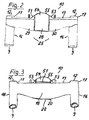
- Fig. 1 shows a transport roller 1, which consists essentially of a wheels 2 Axis 3, a support bracket 5 connected to the axis 3 via bearing blocks 4 and over a receiving plate 6 with axis 3 and support bracket 5 connected tubular Support bars 7, in which telescopic handle bars 8 are guided, the at its end facing away from the axis 3, an unspecified handle exhibit.
- the outer diameter of the handlebars 8 corresponds approximately to that Inner diameter of the support bars 7, so that the handle bars 8 are in the support bars 7 slide.
- the upper part of the through bores 11 of the connecting piece 10 is formed by bores 12, the inside diameter of the outside diameter of the Handlebars 8 are adapted such that the handlebars 8 are practically without or without noteworthy play and appropriate with a slight friction in the holes 12 axially displaceable and depending on the setting of the handlebars 8 to the Dip the support bars 7 more or less deeply into the support bars 7.
- known per se spreading body can be assigned with spring tongues, the one in the lower part of the through hole 11 of the connecting piece 10 located; reach behind not shown stop. Otherwise, this can Spreaders serve in a manner known per se for a certain, constant Friction between the ends of the handlebars 8 and the inner walls the support bars 7 to worry.
- the connector 10 consists of a fixed, in summary with 13th designated part and a part 13 which is movably mounted in relation to it, in summary with 14 designated part.
- the part 13 of the connecting piece 10 consists essentially of a central part 15 and the middle part 15 laterally closing sleeve-like ends 16.
- sleeve-like Ends 16 are the above-mentioned through holes 11 with Holes 9 and 12.
- the holes 12 provided for guiding the handlebars 8 are relative in this case short, ring-like attachments 17 are provided, which extend to a certain extent over the the surrounding surface of part 13 and the top of the drawing Form the end of the through holes 11 mentioned.
- the one to accommodate the relevant ends of the support bars 7 provided holes 9 are in the drawing lower part of the sleeve-like ends 16.
- the diameter of the Bores 9 and 12 are different and in the manner already described adapted to the relevant diameter of the handlebars 7 and 8.
- the central part 15 has an approximately U-shaped cross section and has a central one Wall part 18 on which an upper wall part 19 and a lower one Connect wall part 20. While the upper wall part 19 up to the outer regions of the sleeve-like ends 16 extends and accordingly also includes the bores 12 and the ring-like attachments 17, the middle goes Wall part 18 each in a partially cylindrical region 21 of the wall of the Through hole 11 over.
- the lower wall part 20 runs - symmetrically from starting from a central area 22 - with a decreasing distance from the upper area Wall part 19 to an adjacent wall area 23 of the Through hole 11. In this way is through the wall parts 18, 19 and 20th as well as a space 24 due to the adjoining partially cylindrical regions 21 created, which receives the mentioned, movably mounted in part 13 part 14.
- the movable part 14 of the connecting piece 10 is by means of clamping devices 25 formed, which consists essentially of a knee joint-like actuator 26 with two arranged opposite each other, each in clamping contact with a handle bar 8 bringable ends 27 and a drive connected to the actuator 26 Actuation handle 28 exist.
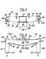
- the actuator 26 consists of two of equal length Articulated arms 29, 30, which in a transverse to the longitudinal axis of handle and support bars 8 and 7 extending plane about a common hinge 31 on Connector 10 are stored.
- the joint 31 consists of a Articulated arm 29 provided pivot pin 32, which is in a on the articulated arm 30 provided articulated bore 33 leads.
- a part-cylindrical groove 34 which as a drive and Serves guide means for the actuator 26 and the drive and guide means corresponds, which in the form of a to be described below
- Actuating handle 28 located adjusting pin 35 with a spherical end 36 are trained.
- the articulated arms 29, 30 each have one at their end remote from the articulation 31 Through opening 37 for a handle bar 8.
- the through openings 37 of the Articulated arms 29, 30 form the middle part of the through bores 11 of the Connector 10.
- the articulated arms are located in the longitudinal direction in the area of the passage openings 37 29, 30 opposite wall areas 38, 39, the mutual Distance is dimensioned such that these wall areas 38, 39 on the relevant Hold handle 8.
- the handlebars 8 inserted through the through openings 37 are shown in dashed lines in FIGS. 9 and 10 of the drawing.
- the articulated arms 29, 30 of the actuator 26 guide and thus hold transverse to Longitudinal axis of the handlebars 8 or transverse to the longitudinal direction of the through openings 37 on the handlebars 8 themselves, while the articulated arms 29, 30 parallel to the longitudinal axis the handlebars 8 through the upper and lower wall part 19 and 20 of the middle part 15 and through the partially cylindrical region 21 and the wall regions 23 Adjacent wall areas held and guided at the sleeve-like ends 16 are.
- the articulated arms 29, 30 of the actuator 26 in the area of Joint 31 also through the already mentioned, corresponding drive and Guide means of actuator 26 and actuating handle 28 and by other areas of the actuating handle 28 which act in a supporting manner are held and guided.
- the articulated arms 29, 30 are partially cylindrical in the area of the articulation 31 to the articulation 31 coaxial support surfaces 40, 41, 42 and 43 assigned.
- the support surfaces 40 and 41 and 42 and 43 each form a pair of support surfaces 40, 41 and 42, 43, respectively Pair of support surfaces 40, 41 assigned to the pivot pin 32 or the joint bore 33 is, while the pair of support surfaces 42, 43 in the articulated arm 29 above Articulated pin 32 and articulated bore 33 adjacent to the partially cylindrical groove 34 is.
- the pairs of support surfaces 40, 41 and 42, 43 complement the joint function of the joint 31 to the extent that these support surface pairs 40, 41 and 42, 43 for Inclusion of in the longitudinal direction of the articulated arms 29, 30 and transverse to the longitudinal axis of the Hinge pin 32 directed compressive forces are suitable and intended.
- the actuating handle 28 already mentioned has at its lower end on the Connection piece 10 facing away from the outside, a groove-like axis guide 44th with which the actuating handle 28 leads on a pivot axis 45 and supports.
- the pivot axis 45 for the actuating handle 28 is within a recess 46 provided, which is centered in the lower wall part 20 of the central part 15 of the connecting piece 10 is located.
- the recess 46 is dimensioned such that it is the groove-like axis guide 44 receives adjacent areas of the actuating handle 28 and leads to the side.
- the actuating handle 28 carries on the side facing the articulated arms 29, 30 at a distance from the axis guide 44 the already mentioned adjusting pin 35 with a spherical End 36.
- the adjusting pin 35 leads with the spherical end 36 in the partially cylindrical groove 34 of the articulated arm 29, the diameter of the spherical End 36 is slightly smaller than the diameter of the groove 34, but is larger than the slot 35 of the groove 34 which faces the adjusting pin 35 and is designated 47 although a relative movement of the adjusting pin 35 with the end 36 in a to the longitudinal axis of the Groove 34 possible in parallel direction, but not a relative movement in a transverse to the longitudinal axis of the groove 34 and the pivot axis 45 Direction. That means the trunnion. 35 with end 36 on the one hand and the partly cylindrical groove 34 on the other hand corresponding drive and Guide means for the actuator 26 on the actuating handle 28 or on Form articulated arm 29 of the actuator 26.
- the adjusting pin 35 with a spherical end 36 is located on a pressure surface 48 acting surface area of a profile-like shaped area 49 on the with 50th designated back of the operating handle 28.
- the pressure surface 48 is at corresponding movement of the actuating handle 28 in pressure contact with opposite areas of the articulated arms 29, 30 can be brought.
- the actuating handle 28 has a tab-like extension 51 with a spacing to the axis guide 44 corresponding curvature.
- the extension 51 is one on the provided upper wall part 19 of the central part 15 of the connecting piece 10, assigned correspondingly curved top surface 52.
- the arrangement is such that the above already mentioned, the lateral guidance of the actuating handle 28 serving pin-like Extensions 53 to the aforementioned rounded course of the edge 55 of the grip area 54 to continue to the adjacent surface area of the upper wall part 19.
- the connector 10 with clamping devices 25 is advantageously made of plastic made, for example, of polypropylene.
- clamping devices 25 on the connector 10 The operation of the clamping devices 25 on the connector 10 is as follows:
- the achievable clamping can thus be predefined in size even better, that the handlebars already in the area of entry into the connecting piece 10 - that is in the area of the bores 12 mentioned - with respect to their mutual spacing defined and held taut in the connector 10.
Landscapes
- Engineering & Computer Science (AREA)
- Chemical & Material Sciences (AREA)
- Combustion & Propulsion (AREA)
- Transportation (AREA)
- Mechanical Engineering (AREA)
- Handcart (AREA)
Abstract
Description
- Fig.1
- einen Transportroller mit einem zwei Trag- und Griffholme aufnehmenden Verbindungsstück mit Klemmvorrichtungen in perspektivischer Darstellung,
- Fig. 2
- eine Vorderansicht des Verbindungsstückes des Transportrollers nach Fig. 1,
- Fig. 3
- eine Rückansicht des Verbindungsstückes nach Fig. 2,
- Fig. 4
- eine Aufsicht auf das Verbindungsstück nach den Fig. 2 und 3,
- Fig. 5
- eine Seitenansicht auf das Verbindungsstück nach den Fig. 2 bis 4,
- Fig. 6
- eine Vorderansicht auf das Verbindungsstück nach den Fig. 2 bis 5, jedoch ohne Klemmvorrichtungen,
- Fig. 7
- eine Aufsicht auf das Verbindungsstück nach Fig. 6, von oben gesehen,
- Fig. 8
- eine Aufsicht auf das Verbindungsstück nach Fig. 6, von unten gesehen,
- Fig. 9
- eine Ansicht des Stellorgans der Klemmvorrichtungen des Verbindungsstückes nach den Fig. 2 bis 5,
- Fig. 10
- eine Aufsicht auf das Stellorgan nach Fig. 9, von oben gesehen,
- Fig. 11
- die Betätigungshandhabe der Klemmvorrichtungen des Verbindungsstückes nach den Fig. 2 bis 5 und 9, 10 in der Seitenansicht und in größerem Maßstab, und
- Fig. 12
- die Betätigungshandhabe nach Fig. 11 in der Rückansicht.
- 1
- Transportroller
- 2
- Räder
- 3
- Achse
- 4
- Lagerböcke
- 5
- Tragbügel
- 6
- Aufnahmeplatte
- 7
- Tragholme
- 8
- Griffholme
- 9
- Bohrungen
- 10
- Verbindungsstück
- 11
- Durchgangsbohrungen
- 12
- Bohrungen
- 13
- Teil, feststehend
- 14
- Teil, beweglich
- 15
- Mittelteil
- 16
- Enden, hülsenartig
- 17
- Aufsätze, ringartig
- 18
- Wandungsteil, mittlerer
- 19
- Wandungsteil, oberer
- 20
- Wandungsteil, unterer
- 21
- Bereich, teilzylindrisch
- 22
- Bereich, mittlerer
- 23
- Wandungsbereich (der Durchgangsbohrungen 11)
- 24
- Raum (für das Stellorgan 26)
- 25
- Klemmvorrichtungen
- 26
- Stellorgan
- 27
- Enden
- 28
- Betätigungshandhabe
- 29
- Gelenkarm
- 30
- Gelenkarm
- 31
- Gelenk
- 32
- Gelenkzapfen
- 33
- Gelenkbohrung
- 34
- Nut, teilzylindrisch
- 35
- Stellzapfen
- 36
- Ende, kugelartig
- 37
- Durchgangsöffnung .
- 38
- Wandungsbereich
- 39
- Wandungsbereich
- 40
- Stützfläche, teilzylindrisch
- 41
- Stützfläche, teilzylindrisch
- 42
- Stützfläche, teilzylindrisch
- 43
- Stützfläche, teilzylindrisch
- 44
- Achsführung, nutartig
- 45
- Schwenkachse
- 46
- Ausnehmung
- 47
- Schlitz (in Nut 34)
- 48
- Druckfläche
- 49
- Bereich
- 50
- Rückseite
- 51
- Fortsatz, laschenartig
- 52
- Deckfläche
- 53
- Fortsätze, zapfenartig
- 54
- Griffbereich
- 55
- Kante
- 56
- Fortsätze, zapfenartig
- 57
- Fortsätze, laschenartig
Claims (30)
- Transportroller (1) mit zwei Tragholmen (7), die an ihrem einen Ende mit einer zwei Räder (2) tragenden Achse (3) sowie mit einem Tragbügel oder Tragrahmen (5) verbunden sind und die an ihrem anderen Ende über ein Verbindungsstück (10) miteinander verbunden sind, das Durchgangsbohrungen (11) für zwei Griffholme (8) aufweist, deren eine Enden über ein Griffstück miteinander verbunden sind und deren andere Enden in den Tragholmen (7) teleskopartig verschiebbar geführt sind, wobei das Verbindungsstück (10) eine Klemmvorrichtung (25) aufweist zum Fixieren der Lage der Griffholme (8) gegenüber den Tragholmen (7), dadurch gekennzeichnet, dass beiden Griffholmen (8) bzw. Tragholmen (7) jeweils eine Klemmvorrichtung (25) im oder am Verbindungsstück (10) zugeordnet ist.
- Transportroller nach Anspruch 1, dadurch gekennzeichnet, dass die Klemmvorrichtungen (25) ein gemeinsames, kniegelenkartig ausgebildetes und von Hand betätigbares Stellorgan (26) aufweisen, dessen Gelenkarme (29, 30) in einer quer zur Längsachse von Griff- und Tragholmen (8 bzw. 7) verlaufenden Ebene um ihr gemeinsames Gelenk (31) schwenkbar im oder am Verbindungsstück (10) gelagert sind und dessen dem Gelenk (31) abgekehrte Enden der Gelenkarme (29, 30) direkt oder indirekt in Klemmkontakt mit dem jeweils benachbarten Griffholm (8) bringbar sind.
- Transportroller nach Anspruch 2, dadurch gekennzeichnet, dass das Stellorgan (26) in einer zur Ebene der Längsachsen von Griff- und Tragholmen (8 bzw. 7) parallelen Ebene und quer zu deren Längsachsen verlaufenden Richtung in gewissem Ausmaß frei beweglich ("schwimmend") im oder am Verbindungsstück (10) gelagert ist zum Erzielen eines selbsttätigen Ausgleichs der von den Gelenkarmen (29, 30) des Stellorgans (26) auf die Griffholme (8) ausgeübten Kräfte.
- Transportroller nach Anspruch 1, dadurch gekennzeichnet, dass die Klemmvorrichtungen (25) jeweils ein kniegelenkartig ausgebildetes und von Hand betätigbares Stellorgan (26) aufweisen, dessen Gelenkarme (29, 30) jeweils in einer quer zur Längsachse von Griff- und Tragholmen (8 bzw. 7) verlaufenden Ebene um ihr jeweils gemeinsames Gelenk (31) schwenkbar im oder am Verbindungsstück (10) gelagert sind und dessen dem Gelenk (31) abgekehrte Enden der Gelenkarme (29, 30) einerseits direkt oder indirekt in Klemmkontakt mit dem jeweils benachbarten einen bzw. anderen Griffholm (8) bringbar sind und sich andererseits an einem Bereich des Verbindungsstückes (10) abstützen.
- Transportroller nach Anspruch 2 oder 4, dadurch gekennzeichnet, dass der Klemmkontakt bei gestreckten Gelenkarmen (29, 30) besteht.
- Transportroller nach Anspruch 5, dadurch gekennzeichnet, dass die dem Klemmkontakt zugeordnete Endstellung der Gelenkarme (29, 30) des Stellorgans (26) um ein gewisses Maß jenseits der Strecklage (des "Totpunktes") des Stellorgans (26) liegt.
- Transportroller nach Anspruch 2 oder 4, dadurch gekennzeichnet, dass der Klemmkontakt bei angewinkelten Gelenkarmen (29, 30) besteht.
- Transportroller nach Anspruch 2 oder 4, dadurch gekennzeichnet, dass der Klemmkontakt durch Druck auf einen Bereich der Griffholme (8) erfolgt.
- Transportroller nach Anspruch 2 oder 4, dadurch gekennzeichnet, dass der Klemmkontakt durch Druck auf einen Bereich der Tragholme (7) erfolgt.
- Transportroller nach Anspruch 9, dadurch gekennzeichnet, dass der für den Klemmkontakt vorgesehene Bereich des Tragholmes (7) als federnder Abschnitt ausgebildet ist.
- Transportroller nach Anspruch 2 oder 4, dadurch gekennzeichnet, dass das Gelenk (31) aus einem an dem einen Gelenkarm (29) befindlichen Gelenkzapfen (32) und einer an dem anderen Gelenkarm (30) vorgesehenen Gelenkbohrung (33) besteht.
- Transportroller nach Anspruch 11, dadurch gekennzeichnet, dass die Gelenkverbindung der Gelenkarme (29, 30) lösbar ist.
- Transportroller nach Anspruch 2 oder 4, dadurch gekennzeichnet, dass den Gelenkarmen (29, 30) im Bereich des Gelenkes (31) befindliche, sich gegeneinander abstützende und zum Gelenk (31) koaxiale, teilzylindrische Stützflächen (40 bis 43) zugeordnet sind.
- Transportroller nach Anspruch 2 oder 4, dadurch gekennzeichnet, dass die Gelenkarme (29, 30) an dem dem Gelenk (31) abgekehrten Ende eine das Hindurchführen eines Griffholmes (8) ermöglichende Durchgangsöffnung (37) aufweisen mit in Längsrichtung des betreffenden Gelenkarmes (29 bzw. 30) sich einander gegenüberliegenden, am Griffholm (8) anliegenden Wandungsbereichen (38, 39).
- Transportroller nach Anspruch 2 oder 4, dadurch gekennzeichnet, dass der obere Bereich der im Verbindungsstück (10) vorgesehenen Durchgangsbohrungen (11) dem Außendurchmesser eines Griffholmes (8) angepasst ist.
- Transportroller nach Anspruch 2 oder 4, dadurch gekennzeichnet, dass den Gelenkarmen (29, 30) eine Betätigungshandhabe (28) zugeordnet ist, die am Verbindungsstück (10) um eine parallel zur Schwenkebene der Gelenkarme (29, 30) sowie parallel zur Ebene der Griff- bzw. Tragholme (8 bzw. 7) verlaufende Schwenkachse (45) schwenkbar am Verbindungsstück (10) gelagert ist und Antriebs- und Führungsmittel (Stellzapfen 35, kugelartiges Ende 36) aufweist, die mit im Bereich des Gelenkes (31) am einen und/oder am anderen Gelenkarm (29 bzw. 30) vorgesehenen Antriebs- und Führungsmitteln (teilzylindrische Nut 34) korrespondieren.
- Transportroller nach Anspruch 16, dadurch gekennzeichnet, dass das am Gelenk (31) vorgesehene Antriebs- und Führungsmittel als teilzylindrische Nut (34) und das an der Betätigungshandhabe (28) vorgesehene Antriebs- und Führungsmittel als Stellzapfen (35) ausgebildet ist, der sich mit einem am freien Ende des Stellzapfens (35) befindlichen, kugelartigen Ende (36) in der erwähnten teilzylindrischen Nut (34) führt.
- Transportroller nach Anspruch 17, dadurch gekennzeichnet, dass die im Bereich des Gelenkes (31) vorgesehenen Antriebs- und Führungsmittel (Nut 34) achsparallel zum Gelenk (31) in dem einen Gelenkarm (29) vorgesehen sind.
- Transportroller nach Anspruch 18, dadurch gekennzeichnet, dass die im Bereich des Gelenkes (31) vorgesehenen Antriebs- und Führungsmittel (Nut 34) koaxial zum Gelenk (31) in dem einen Gelenkarm (29) vorgesehen sind.
- Transportroller nach Anspruch 18, dadurch gekennzeichnet, dass sich die im Bereich des Gelenkes (31) der Gelenkarme (29, 30) vorgesehenen Antriebs-und Führungsmittel (Nut 34) im Gebrauchszustand des Transportrollers (1) oberhalb bzw. unterhalb des Gelenkes (31) befinden.
- Transportroller nach Anspruch 16, dadurch gekennzeichnet, dass die Schwenkachse (45) für die Betätigungshandhabe (28) innerhalb einer benachbarte Bereiche der Betätigungshandhabe (28) aufnehmenden Ausnehmung (46) im Mittelteil (15) des Verbindungsstückes (10) vorgesehen ist.
- Transportroller nach Anspruch 16, dadurch gekennzeichnet, dass der Schwenkachse (45) für die Betätigungshandhabe (28) eine auf der dem Verbindungsstück (10) abgekehrten Seite der Betätigungshandhabe (28) befindliche nutartige Achsführung (44) in der Betätigungshandhabe (28) zugeordnet ist.
- Transportroller nach Anspruch 16, dadurch gekennzeichnet, dass die Betätigungshandhabe (28) auf der dem Gelenk (31) bzw. den im Bereich des Gelenkes (31) vorgesehenen Antriebs- und Führungsmitteln (Nut 34) zugekehrten Seite eine in Druckkontakt mit dem Gelenk (31) bzw. den erwähnten Antriebs- und Führungsmitteln (Nut 34) bringbare Druckfläche (48) aufweist.
- Transportroller nach Anspruch 16, dadurch gekennzeichnet, dass die Betätigungshandhabe (28) an ihrem der nutartigen Achsführung (44) abgekehrten Ende einen laschenartigen Fortsatz (51) mit einer dem Abstand zu dieser Achsführung (44) bzw. zur Schwenkachse (45) der Betätigungshandhabe (28) entsprechenden Krümmung aufweist, dem eine entsprechend gekrümmte Deckfläche (52) am Verbindungsstück (10) zugeordnet ist.
- Transportroller nach Anspruch 24, dadurch gekennzeichnet, dass seitlich neben der Deckfläche (52) für den laschenartigen Fortsatz (51) der Betätigungshandhabe (28) und in einer quer zur Bewegungsrichtung dieses Fortsatzes (51) verlaufenden Flucht liegend zapfenartige Fortsätze (53) am Verbindungsstück (10) vorgesehen sind, die mit einem gewissen geringen Abstand an das der Schwenkachse (45) abgekehrte Ende der Betätigungshandhabe (28) anschließend an das Verbindungsstück (10) angeformt sind und zwischen denen sich der laschenartige Fortsatz (51) der Betätigungshandhabe (28) führt.
- Transportroller nach Anspruch 16, dadurch gekennzeichnet, dass das der Schwenkachse (45) abgekehrte Ende der Betätigungshandhabe (28) um ein gewisses Maß über den benachbarten Oberflächenbereich des Verbindungsstückes (10) auskragt, so dass ein gegenüber diesem Bereich des Verbindungsstückes (10) sich abhebender Griffbereich (54) gebildet ist.
- Transportroller nach Anspruch 26, dadurch gekennzeichnet, dass die Kante (55) des der Schwenkachse (45) abgekehrten, den Griffbereich (54) bildenden Endes der Betätigungshandhabe (28) einen gerundeten Verlauf hat derart, dass die beiden Enden dieser Kante (55) jeweils dem benachbarten Bereich des Verbindungsstückes (10) naheliegen.
- Transportroller nach Anspruch 25 und 27, dadurch gekennzeichnet, dass die zapfenartigen Fortsätze (53) den Kantenverlauf des erwähnten Griffbereiches (54) der Betätigungshandhabe (28) bis zu dem benachbarten Oberflächenbereich des Verbindungsstückes (10) fortsetzen.
- Transportroller nach Anspruch 1, dadurch gekennzeichnet, dass Verbindungsstück (10) und Klemmvorrichtungen (25) aus Kunststoff bestehen.
- Anwendung der Erfindung nach Anspruch 2 oder 4 auf Transportroller mit einem gewissen Abstand voneinander befindlichen und parallel zueinander verlaufenden Griffholmen/Tragholmen.
Applications Claiming Priority (2)
| Application Number | Priority Date | Filing Date | Title |
|---|---|---|---|
| DE20010817U | 2000-06-17 | ||
| DE20010817U DE20010817U1 (de) | 2000-06-17 | 2000-06-17 | Transportroller mit zwei Trag- und Griffholmen |
Publications (3)
| Publication Number | Publication Date |
|---|---|
| EP1164069A2 true EP1164069A2 (de) | 2001-12-19 |
| EP1164069A3 EP1164069A3 (de) | 2003-07-02 |
| EP1164069B1 EP1164069B1 (de) | 2008-05-07 |
Family
ID=7942996
Family Applications (1)
| Application Number | Title | Priority Date | Filing Date |
|---|---|---|---|
| EP20010114467 Expired - Lifetime EP1164069B1 (de) | 2000-06-17 | 2001-06-15 | Transportroller mit zwei Trag- und Griffholmen |
Country Status (2)
| Country | Link |
|---|---|
| EP (1) | EP1164069B1 (de) |
| DE (1) | DE20010817U1 (de) |
Citations (1)
| Publication number | Priority date | Publication date | Assignee | Title |
|---|---|---|---|---|
| DE9116974U1 (de) | 1991-08-17 | 1994-12-22 | Leifheit Ag, 56377 Nassau | Transportroller |
Family Cites Families (4)
| Publication number | Priority date | Publication date | Assignee | Title |
|---|---|---|---|---|
| US5461756A (en) * | 1994-08-23 | 1995-10-31 | Wang; King-Sheng | Retractable luggage handle release control and inner tube positioning arrangement |
| US5513873A (en) * | 1994-10-18 | 1996-05-07 | Chen; Shou-Mao | Adjustable handle assembly for push cart |
| US5595092A (en) * | 1995-03-24 | 1997-01-21 | Cheng; Chin-Chang | Positioning device of retractable bars of a trolley |
| DE29700507U1 (de) * | 1997-01-14 | 1997-02-20 | Günter Andersen Metallwarenfabrik, 24986 Satrup | Transportroller |
-
2000
- 2000-06-17 DE DE20010817U patent/DE20010817U1/de not_active Expired - Lifetime
-
2001
- 2001-06-15 EP EP20010114467 patent/EP1164069B1/de not_active Expired - Lifetime
Patent Citations (1)
| Publication number | Priority date | Publication date | Assignee | Title |
|---|---|---|---|---|
| DE9116974U1 (de) | 1991-08-17 | 1994-12-22 | Leifheit Ag, 56377 Nassau | Transportroller |
Also Published As
| Publication number | Publication date |
|---|---|
| EP1164069B1 (de) | 2008-05-07 |
| EP1164069A3 (de) | 2003-07-02 |
| DE20010817U1 (de) | 2000-12-21 |
Similar Documents
| Publication | Publication Date | Title |
|---|---|---|
| EP0904760B1 (de) | Kreuzstrebe für einen Faltrollstuhl | |
| DE9314000U1 (de) | Reisesportwagen mit einem zusammenlegbaren Rohrrahmengestell | |
| WO2001005646A1 (de) | Roller | |
| EP2165893B1 (de) | Eine ein schleppfähiges, schwenkbares Stützrad aufweisende Stützanordnung für mobile Objekte | |
| DE19707799B4 (de) | Arbeitsgerüst mit heb- und senkbarem Ausleger | |
| EP1055487A1 (de) | Zange mit parallelen Backen | |
| EP4006241A1 (de) | Stangenmontierbare haltevorrichtung und sanitäre handbrausenhalteeinrichtung | |
| EP0830976B1 (de) | Fahrzeugtransporter | |
| WO2014071988A1 (de) | Schiebewagen, insbesondere kinderwagen | |
| EP1164069A2 (de) | Transportroller mit zwei Trag- und Griffholmen | |
| CH690750A5 (de) | Klapprollstuhl. | |
| EP0723058B1 (de) | Bremse, insbesondere für einen Oberlichtflügel | |
| DE19522967B4 (de) | Integrierbarer Kindersitz für einen Kraftfahrzeugsitz | |
| DE10355059A1 (de) | Von Hand bewegbarer Transportwagen | |
| DE4026392C2 (de) | Knickstütze für die Aufstelldächer von Fahrzeugen oder dergleichen | |
| DE102006048279B4 (de) | Tisch | |
| EP3375666B1 (de) | Lastenträger, insbesondere fahrradträger | |
| DE2300750A1 (de) | Gerueststuetze | |
| AT518572A1 (de) | Gelenk | |
| DE3412755A1 (de) | Ausfahrbares fahrwerk fuer einen standkoerper | |
| DE1457677C2 (de) | Kupplungsvorrichtung zum Anschließen von Anbaugeräten an das Dreipunktgestänge von Schleppern | |
| AT526950B1 (de) | Führungsanordnung zur Führung eines bewegbaren Möbelteils | |
| DE102006023179A1 (de) | Anbauvorrichtung für eine Landmaschine | |
| DE8715318U1 (de) | Transportgerät | |
| DE2841563C2 (de) |
Legal Events
| Date | Code | Title | Description |
|---|---|---|---|
| PUAI | Public reference made under article 153(3) epc to a published international application that has entered the european phase |
Free format text: ORIGINAL CODE: 0009012 |
|
| AK | Designated contracting states |
Kind code of ref document: A2 Designated state(s): AT BE CH CY DE DK ES FI FR GB GR IE IT LI LU MC NL PT SE TR |
|
| AX | Request for extension of the european patent |
Free format text: AL;LT;LV;MK;RO;SI |
|
| PUAL | Search report despatched |
Free format text: ORIGINAL CODE: 0009013 |
|
| AK | Designated contracting states |
Designated state(s): AT BE CH CY DE DK ES FI FR GB GR IE IT LI LU MC NL PT SE TR |
|
| AX | Request for extension of the european patent |
Extension state: AL LT LV MK RO SI |
|
| 17P | Request for examination filed |
Effective date: 20030806 |
|
| AKX | Designation fees paid |
Designated state(s): FR GB IT NL |
|
| REG | Reference to a national code |
Ref country code: DE Ref legal event code: 8566 |
|
| 17Q | First examination report despatched |
Effective date: 20061026 |
|
| 17Q | First examination report despatched |
Effective date: 20061026 |
|
| GRAP | Despatch of communication of intention to grant a patent |
Free format text: ORIGINAL CODE: EPIDOSNIGR1 |
|
| GRAS | Grant fee paid |
Free format text: ORIGINAL CODE: EPIDOSNIGR3 |
|
| GRAA | (expected) grant |
Free format text: ORIGINAL CODE: 0009210 |
|
| AK | Designated contracting states |
Kind code of ref document: B1 Designated state(s): FR GB IT NL |
|
| REG | Reference to a national code |
Ref country code: GB Ref legal event code: FG4D Free format text: NOT ENGLISH |
|
| PLBE | No opposition filed within time limit |
Free format text: ORIGINAL CODE: 0009261 |
|
| STAA | Information on the status of an ep patent application or granted ep patent |
Free format text: STATUS: NO OPPOSITION FILED WITHIN TIME LIMIT |
|
| 26N | No opposition filed |
Effective date: 20090210 |
|
| PGFP | Annual fee paid to national office [announced via postgrant information from national office to epo] |
Ref country code: FR Payment date: 20100617 Year of fee payment: 10 |
|
| PGFP | Annual fee paid to national office [announced via postgrant information from national office to epo] |
Ref country code: IT Payment date: 20100623 Year of fee payment: 10 |
|
| PGFP | Annual fee paid to national office [announced via postgrant information from national office to epo] |
Ref country code: NL Payment date: 20100607 Year of fee payment: 10 |
|
| PGFP | Annual fee paid to national office [announced via postgrant information from national office to epo] |
Ref country code: GB Payment date: 20100401 Year of fee payment: 10 |
|
| REG | Reference to a national code |
Ref country code: NL Ref legal event code: V1 Effective date: 20120101 |
|
| GBPC | Gb: european patent ceased through non-payment of renewal fee |
Effective date: 20110615 |
|
| PG25 | Lapsed in a contracting state [announced via postgrant information from national office to epo] |
Ref country code: IT Free format text: LAPSE BECAUSE OF NON-PAYMENT OF DUE FEES Effective date: 20110615 |
|
| REG | Reference to a national code |
Ref country code: FR Ref legal event code: ST Effective date: 20120229 |
|
| PG25 | Lapsed in a contracting state [announced via postgrant information from national office to epo] |
Ref country code: FR Free format text: LAPSE BECAUSE OF NON-PAYMENT OF DUE FEES Effective date: 20110630 |
|
| PG25 | Lapsed in a contracting state [announced via postgrant information from national office to epo] |
Ref country code: NL Free format text: LAPSE BECAUSE OF NON-PAYMENT OF DUE FEES Effective date: 20120101 |
|
| PG25 | Lapsed in a contracting state [announced via postgrant information from national office to epo] |
Ref country code: GB Free format text: LAPSE BECAUSE OF NON-PAYMENT OF DUE FEES Effective date: 20110615 |