EP1163838B1 - Machine de récolte, notamment presse à balles rondes - Google Patents
Machine de récolte, notamment presse à balles rondes Download PDFInfo
- Publication number
- EP1163838B1 EP1163838B1 EP01113498A EP01113498A EP1163838B1 EP 1163838 B1 EP1163838 B1 EP 1163838B1 EP 01113498 A EP01113498 A EP 01113498A EP 01113498 A EP01113498 A EP 01113498A EP 1163838 B1 EP1163838 B1 EP 1163838B1
- Authority
- EP
- European Patent Office
- Prior art keywords
- pick
- spring
- link
- crop harvester
- frame
- Prior art date
- Legal status (The legal status is an assumption and is not a legal conclusion. Google has not performed a legal analysis and makes no representation as to the accuracy of the status listed.)
- Expired - Lifetime
Links
Images


Classifications
-
- A—HUMAN NECESSITIES
- A01—AGRICULTURE; FORESTRY; ANIMAL HUSBANDRY; HUNTING; TRAPPING; FISHING
- A01D—HARVESTING; MOWING
- A01D89/00—Pick-ups for loaders, chaff-cutters, balers, field-threshers, or the like, i.e. attachments for picking-up hay or the like field crops
- A01D89/004—Mountings, e.g. height adjustment, wheels, lifting devices
-
- A—HUMAN NECESSITIES
- A01—AGRICULTURE; FORESTRY; ANIMAL HUSBANDRY; HUNTING; TRAPPING; FISHING
- A01F—PROCESSING OF HARVESTED PRODUCE; HAY OR STRAW PRESSES; DEVICES FOR STORING AGRICULTURAL OR HORTICULTURAL PRODUCE
- A01F15/00—Baling presses for straw, hay or the like
- A01F15/08—Details
- A01F15/10—Feeding devices for the crop material e.g. precompression devices
- A01F15/106—Feeding devices for the crop material e.g. precompression devices for round balers
Definitions
- the invention relates to a harvesting machine, in particular round baler, with a frame, a transducer with a frame, and with a resilient suspension between the frame for receiving at least a portion of the weight of the pick-up, wherein the pick-up has a greater width than the frame of the harvesting machine and attached to this vertically pivotable.
- the brochure "CLAAS Rollant 66 46 Silage 46 Roto Cut”, print 8/95 (M + E) dt. 150 / 190.469.7 discloses a round baler with a so-called wide pick-up, so a pickup, the side of the frame of the round baler surmounted.
- the height of the pick-up is influenced by a spring, which is hinged at one end to the frame of the round baler and the other end acts on a lever arm, which is placed on a transverse to the round baler shaft at one end. At the other end of the shaft, a lever arm is also provided, which acts via a link on the pickup.
- a press has a pickup that is as wide as a subsequent press channel and that has a spring extending between the picker and a frame of the press to resiliently support the picker.
- both the spring force and the lever arm to the pivot axis of the pickup increases, which causes it to swing slightly upwards.
- the spring could not be connected in the intended manner to the transducer.
- a suspension according to the US Pat. No. 4,085,571 also has a tension spring, but engages on a projecting from the transducer bearing on this and is close to the pivot axis of the pickup; Consequently, high spring forces are required. If you wanted to keep the spring forces low, the bearing would have to be located much further away from the transducer, which in turn takes up much space.
- the problem underlying the invention is seen in the fact that too many parts are required to accommodate the weight of the pickup, that can accumulate on the suspension crop, that the suspension can not be used in wide pickups and / or high spring forces are required.
- a recess for.
- a slot, a large hole or the like in the handlebar in which with more or less play a connected to the pickup pin, bolt, shaft or the like is taken, avoids jamming of the handlebar on the pin or the like during movement of the pickup , Especially when the transducer rotates in itself, which is constantly the case during rough operation.
- a kidney-shaped recess has the advantage that the pin or the like can not be moved with too much play in the recess while it retains sufficient freedom of movement in the required range of motion.
- a gap is provided between the side walls or the side parts of the pickup and the harvesting machine. Each handlebar can pass through this gap and is thereby shielded from crops
- the number of required parts can be kept low, if an existing axis of rotation is also used as a pivot axis; As a result, bearings multiply and a wave z. B. can be used as a hub.
- a harvesting machine 10 is shown in the manner of a round baler for making large cylindrical bales.
- the harvesting machine 10 includes a main frame 12 carried by ground wheels 13, at the front of which is connected a drawbar 14 for connection to a towing vehicle, such as an agricultural tractor not shown in the drawing.
- the frame 12 includes opposed side walls 15 having a plurality of ball-forming rollers 18 extending therebetween and rotatably supported therein.
- the plurality of ball forming rollers 18 are of equal diameter, one roller being a bottom roller 20 having a larger diameter than the remaining rollers 18 and spaced from a front one of the rollers 18 to form an inlet 22 for the baling chamber 16. It will be understood from the following description that the invention described herein may also be applied to a large baler having an augmentable baling chamber, or even other agricultural equipment used to perform processes with crops deposited on swaths.
- a pickup 24 and a subsequent conveyor 26 for picking up harvested on swaths crop and its promotion to the inlet 22 is mounted.
- the pickup 24 is called a so-called broad Pick-up formed, which has a greater width than the baling chamber 16, and which is provided with the additional conveyor 26 to narrow the incoming flow of the conveyed material to the width of the baling chamber 16 before the crop reaches the inlet 22, wherein the Conveyor 26 is equipped with right and left worm for merging the crop, of which only the left worm 28 is shown here.
- a plurality of rigid conveyor fingers 30 are mounted at equal intervals in the transverse direction to each other between the screws.
- the receiver 24 includes a frame 32 which includes a tine winder with a plurality of spring tines 34 which receive crops deposited on swaths and pass the crop stream back to the conveyor 26.
- the frame 32 includes transversely spaced upstanding side members 36 extending upwardly and rearwardly and mounted to provide a rotatable connection that allows the susceptor 24 to float vertically about the axis of rotation of the screws 28 and the conveyor fingers 30.
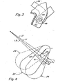
- each of the suspensions 37 each includes a spring 38 formed as a helical tension spring, the upper end of which is connected to a holder 40 for receiving the end of the spring 38 held by a support 42 fixed to the frame 12.
- the lower end of the spring 38 terminates as a hook which is received in a recess at the upper end portion of a longer leg of an L-shaped link 44 made of a flat steel.
- the long leg of the handlebar 44 extends beyond the frame 32 in an area outside a wall of the frame 12, the drive shaft of the In FIG.
- the handlebar 44 has a forwardly directed, short, lower end region with a kidney-shaped recess 46, the arcuate surface of which forms an approximately radius around the recess is, in which the hook is received at the end of the spring 38.
- Attached to the side members 36 is a pin 48 which carries a clamped cylindrical connector 50 received in the kidney-shaped recess 46 for movement between the opposite ends.
- the kidney-shaped recess 46 is oriented to allow the cylindrical connector 50 to move along the recess 46 instead of being forced to pivot during swimming operation when the round baler 10 travels over uneven terrain.
- the recess 46 and connector 50 are attached to the rear bottom of the susceptor 24 because the working environment in this area is relatively clean, which also contributes to free movement of the connector 50 within the recess 46, which in turn reduces the wear of the connected parts.
- An abutment link 52 the forward end portion of which is pivotally mounted on the pin 48 and the rearward portion of which is provided with a slot or slot 54 received on a pin 56 secured to the frame 12, is provided to abut a stop limit of the picker 24 to form up. When the receiver 24 is pivoted upward, the pin 56 moves to the rear end of the groove 54.
- the worms 28 operate within a worm assembly formed by rear and front housing members 62 and 64, respectively, with the rear housing member 62 connected to the frame 12 and the front housing member 64 forming part of the frame 32 of the pickup 24 forms.
- a lower one Rearward portion 66 of front housing portion 64 overlaps and extends below a lower forward end portion of rearward housing portion 62 so that front housing portion 64 is allowed to move freely with respect to rearward housing portion 62 as susceptor 24 moves vertically.
- the front housing part 66 is angled upward, namely from front to back, so that a falling through / penetration of Erntegutteilchen by a gap or gap d is prevented, between the housing part 66 and the rear housing part 62 is formed when the pickup 24 is in the normal working range, as shown in Figure 2.
- the front housing 66 tilts from front to back down so that water can drain and crops fall through the gap d to the ground, so that the accumulation of moisture and / or Crop is avoided which would otherwise cause corrosion and / or spoilage of crop, which would result in increased frictional resistance between the crop movement and / or pivotal movement of the picker 24.
- the transducer 24 is shown in various positions about a pivot axis X, which is defined by a rotor shaft 27 of the downstream conveyor 26.
- the transducer 24 is shown by solid lines in an intermediate operating position, in broken lines in a fully raised transport position and with dashed dotted lines in a lowered working position.
- the line of action of the suspension 37 at the mid-working position is along the line L1, giving a lever arm length d1 to the pivot axis X.
- the spring 38 would then be in an intermediate stretch state so as to exert an average amount of force. If the transducer 24 pivots up into its transport position, the spring 38 becomes more and more contracted, so that it exerts less and less force on the pickup 24.
- the lever arm increases to a maximum length d2 , as is the case when the pickup 24 reaches its transport position.
- the spring 38 is increasingly stretched, so that their tensile force on the pickup 24 increases, wherein the spring 38 assumes a Wirkkraftline L3 when the pickup 24 is in its lowermost position.
- the lever arm decreases to a minimum lever arm d3, which is the case when the pickup 24 reaches its lowest position.
- the geometric relationship of the mounting points of the suspension 37 to the pivot axis X is chosen so that the lifting force exerted by the suspension 37 on the receiver 24, substantially equal to the entire acting around the pivot axis X weight of the pickup 24 and over the entire swimming area of the pickup 24 remains substantially constant. It will be understood by one skilled in the art that the specific float adjustments must be made, e.g. B. by changing the forces on one or both sides of the transducer 24 or by changing the Anlenkungsgeometrie.
Landscapes
- Life Sciences & Earth Sciences (AREA)
- Environmental Sciences (AREA)
- Harvesting Machines For Root Crops (AREA)
- Soil Working Implements (AREA)
- Harvesting Machines For Specific Crops (AREA)
- Hydroponics (AREA)
- Harvester Elements (AREA)
Claims (6)
- Machine de récolte (10), en particulier presse à balles rondes, comportant un cadre (12), un ramasseur (24) avec un cadre (32), et comportant une suspension (37) flexible entre les cadre (12, 32) destinée à absorber au moins une partie du poids du ramasseur (24), ledit ramasseur (24) ayant une largeur supérieure à celle du cadre (12) de la machine de récolte (10) et étant monté de manière pivotante dans le sens vertical contre celui-ci, caractérisée en ce que :a) la suspension (37) comporte un ressort (38) et un bielle (44), le ressort (38) étant assemblé au cadre (12) de la machine de récolte (10) et le bielle (44) étant assemblé au cadre (32) du ramasseur (24), et le bielle (44) s'engageant en dessous du ramasseur (24), en particulier dans la zone s'avançant au-delà du cadre (12) de la machine de récolte (10),b) la position des lignes de force (L1, L2, L3) du ressort (38) avec le bielle (44) par rapport à l'axe de pivotement (X) du ramasseur (24) et le type de ressort (38) sont choisis de telle sorte que le produit formé par la force de ressort et le bras de levier autour du point de pivotement (X) est sensiblement constant dans chaque position du ramasseur (24), etc) le ressort (38) est réalisé sous forme de ressort de traction, l'axe de pivotement (X) du ramasseur (24) est toujours disposé entre les points de contact du ressort (38) et du bielle (44) et le centre de gravité du ramasseur (24) se situe par rapport à l'axe de pivotement (X) sur le même côté que le ressort (38) et le bielle (44).
- Machine de récolte selon la revendication 1, caractérisée en ce que le bielle (44) est réalisé en forme de L ou de J, sachant que dans une branche, formant une partie inférieure, du bielle (44) est réalisé un évidement (46), destiné à recevoir avec un jeu un téton (48) réalisé sur le ramasseur (24), ou sur le cadre (32) de celui-ci.
- Machine de récolte selon la revendication 2, caractérisée en ce que l'évidement (46) est réalisé avec une forme réniforme.
- Machine de récolte selon une ou plusieurs des revendications précédentes, caractérisée en ce qu'en aval du ramasseur (24) est monté un convoyeur (26), qui est monté rotatif dans des parois latérales (15) de la machine de récolte (10), des parties latérales (36) du ramasseur (24) étant situées à une distance de celui-ci permettant le passage du bielle (44).
- Machine de récolte selon une ou plusieurs des revendications précédentes, caractérisée en ce que les parties latérales (36) du ramasseur (24) sont aptes à pivoter autour de l'axe de rotation du convoyeur (26).
- Machine de récolte selon une ou plusieurs des revendications précédentes, caractérisée en ce que le convoyeur (26) est entouré au niveau du fond par un carter (62, 64, 66) en plusieurs parties, dont les parties (62, 64, 66) sont mobiles les unes par rapport aux autres et forment une fente (d) ouverte vers le bas lorsque le ramasseur (24) est en position haute.
Applications Claiming Priority (2)
| Application Number | Priority Date | Filing Date | Title |
|---|---|---|---|
| US594251 | 2000-06-15 | ||
| US09/594,251 US6449936B1 (en) | 2000-06-15 | 2000-06-15 | Pick-up floatation suspension |
Publications (2)
| Publication Number | Publication Date |
|---|---|
| EP1163838A1 EP1163838A1 (fr) | 2001-12-19 |
| EP1163838B1 true EP1163838B1 (fr) | 2007-10-31 |
Family
ID=24378145
Family Applications (1)
| Application Number | Title | Priority Date | Filing Date |
|---|---|---|---|
| EP01113498A Expired - Lifetime EP1163838B1 (fr) | 2000-06-15 | 2001-06-02 | Machine de récolte, notamment presse à balles rondes |
Country Status (9)
| Country | Link |
|---|---|
| US (1) | US6449936B1 (fr) |
| EP (1) | EP1163838B1 (fr) |
| AR (1) | AR033674A1 (fr) |
| AT (1) | ATE376767T1 (fr) |
| AU (1) | AU775883B2 (fr) |
| BR (1) | BR0102405B1 (fr) |
| CA (1) | CA2350300C (fr) |
| DE (1) | DE50113184D1 (fr) |
| MX (1) | MXPA01006028A (fr) |
Families Citing this family (8)
| Publication number | Priority date | Publication date | Assignee | Title |
|---|---|---|---|---|
| US20070251203A1 (en) * | 2006-04-26 | 2007-11-01 | Deere & Company, A Delaware Corporation | Dual conveyor system for a combine feeder house |
| DE202007004530U1 (de) * | 2007-03-28 | 2007-05-24 | B. Strautmann & Söhne GmbH u. Co. KG | Ladevorrichtung an einer Erntemaschine |
| US8371097B1 (en) * | 2011-09-26 | 2013-02-12 | Cnh America Llc | Baler gathering wheel height adjustment |
| BE1020227A3 (nl) * | 2011-10-10 | 2013-06-04 | Cnh Belgium Nv | Opraapeenheid met beweegbaar windscherm. |
| US11401053B2 (en) * | 2018-12-20 | 2022-08-02 | The Boeing Company | Autonomous control of electric power supplied to a thruster during electric orbit raising |
| US11396388B2 (en) | 2018-12-20 | 2022-07-26 | The Boeing Company | Optimized power balanced variable thrust transfer orbits to minimize an electric orbit raising duration |
| US11753188B2 (en) | 2018-12-20 | 2023-09-12 | The Boeing Company | Optimized power balanced low thrust transfer orbits utilizing split thruster execution |
| US11013174B2 (en) * | 2019-05-09 | 2021-05-25 | Cnh Industrial America Llc | Floatation adjustment device |
Family Cites Families (13)
| Publication number | Priority date | Publication date | Assignee | Title |
|---|---|---|---|---|
| US2757602A (en) * | 1951-10-30 | 1956-08-07 | Sperry Rand Corp | Automatic pick-up baler |
| US2839981A (en) * | 1955-12-13 | 1958-06-24 | Int Harvester Co | Mounting means for a baler on a tractor |
| CH426351A (de) * | 1963-06-13 | 1966-12-15 | Patent Concern Nv | Wagen mit einem Aufnahmegerät |
| DE1187057B (de) * | 1964-02-17 | 1965-02-11 | Friedhelm Claas | Vorrichtung zur Hoehenverstellung einer Aufsammelvorrichtung fuer im Schwad liegendes halmfoermiges Erntegut |
| US3798885A (en) * | 1972-09-01 | 1974-03-26 | Sperry Rand Corp | Baler pickup counter-balancing mechanism and pickup rope lift |
| US3939631A (en) * | 1974-06-03 | 1976-02-24 | Sperry Rand Corporation | Hay roll forming machine |
| GB1543324A (en) * | 1975-05-02 | 1979-04-04 | Clayson Nv | Resilient mounting of attachment for agricultural machinery |
| US4187666A (en) * | 1977-06-24 | 1980-02-12 | Sperry Rand Corporation | Baler pickup counter balancing means |
| EP0456771A1 (fr) * | 1989-09-07 | 1991-11-21 | Josef Nusser | Dispositif collecteur de paille |
| DE19616999A1 (de) * | 1996-04-27 | 1997-10-30 | Deere & Co | Aufnehmer |
| GB2313089A (en) * | 1996-05-14 | 1997-11-19 | Ford New Holland Nv | Baling, crop collecting and wrapping |
| AT1641U1 (de) * | 1996-10-17 | 1997-09-25 | Otto Gruber Ges M B H Maschbau | Ladewagen |
| US6212865B1 (en) * | 1999-02-26 | 2001-04-10 | H&S Manufacturing Co., Inc. | Windrow merger |
-
2000
- 2000-06-15 US US09/594,251 patent/US6449936B1/en not_active Expired - Lifetime
-
2001
- 2001-06-02 DE DE50113184T patent/DE50113184D1/de not_active Expired - Lifetime
- 2001-06-02 EP EP01113498A patent/EP1163838B1/fr not_active Expired - Lifetime
- 2001-06-02 AT AT01113498T patent/ATE376767T1/de not_active IP Right Cessation
- 2001-06-12 CA CA002350300A patent/CA2350300C/fr not_active Expired - Fee Related
- 2001-06-14 MX MXPA01006028A patent/MXPA01006028A/es active IP Right Grant
- 2001-06-14 AR ARP010102854A patent/AR033674A1/es not_active Application Discontinuation
- 2001-06-14 AU AU51917/01A patent/AU775883B2/en not_active Ceased
- 2001-06-18 BR BRPI0102405-1A patent/BR0102405B1/pt not_active IP Right Cessation
Also Published As
| Publication number | Publication date |
|---|---|
| BR0102405B1 (pt) | 2009-01-13 |
| US6449936B1 (en) | 2002-09-17 |
| BR0102405A (pt) | 2002-03-05 |
| AU775883B2 (en) | 2004-08-19 |
| AU5191701A (en) | 2001-12-20 |
| CA2350300A1 (fr) | 2001-12-15 |
| CA2350300C (fr) | 2004-09-21 |
| DE50113184D1 (de) | 2007-12-13 |
| MXPA01006028A (es) | 2004-11-10 |
| EP1163838A1 (fr) | 2001-12-19 |
| AR033674A1 (es) | 2004-01-07 |
| ATE376767T1 (de) | 2007-11-15 |
Similar Documents
| Publication | Publication Date | Title |
|---|---|---|
| DE60219756T2 (de) | Gerät zur Behandlung von Erntegut | |
| EP1389413B1 (fr) | Articulation d'une tondeuse latérale et ses dispositifs auxiliaires avec une structure de support pour la fixation sur un tracteur ou un véhicule porteur | |
| DE2851035A1 (de) | Maschine zum aufwickeln von faserigem erntegut zu grossen rundballen | |
| DE19841598A1 (de) | Fördervorrichtung für / an landwirtschaftlichen Erntefahrzeugen | |
| EP0651940B2 (fr) | Dent à ressort, dispositif convoyeur et moissonneuse | |
| DE4127155C2 (de) | Niederhaltevorrichtung | |
| EP1155609B1 (fr) | Dispositif d'andainage | |
| DE4220005C2 (de) | Vorrichtung zum Aufnehmen, Transportieren, Zerkleinern und Austragen von Futter- oder Streumitteln | |
| EP0651939B1 (fr) | Strippeur pour dispositif convoyeur sur une moissonneuse | |
| DE2530249B2 (de) | Wickelballenpresse | |
| EP1163838B1 (fr) | Machine de récolte, notamment presse à balles rondes | |
| EP0499909A1 (fr) | Presse à balles rondes | |
| DE1938698A1 (de) | Aufhaengung fuer eine Maeheinheit in einer Landmaschine | |
| DE102012011591C5 (de) | Aufnahmevorrichtung für eine landwirtschaftliche Erntemaschine | |
| EP1362506A1 (fr) | Ramasseur et dispositif de contrôle de la hauter | |
| DE10251827A1 (de) | Gutaufnehmer | |
| DE2632002C2 (de) | Mähmaschine | |
| DE3519776A1 (de) | Foerdervorrichtung fuer landwirtschaftliche ladewagen | |
| DE2926764A1 (de) | Zufuehrungsvorrichtung zum mattenfoermigen zufuehren von erntegut zu einem schneid- oder zerkleinerungskopf | |
| EP1738634A1 (fr) | Dispositif de ramassage de produits de récolte ainsi que machine de récolte. | |
| DE19750954A1 (de) | Aufnahmeeinrichtung einer landwirtschaftlichen Erntemaschine | |
| DE2902500C2 (de) | Aufnahmevorrichtung für einen Feldhäcksler | |
| DE102018123990A1 (de) | Betätigungshebel für eine Erntemaschine mit einer Schneidvorrichtung | |
| DE69813336T2 (de) | Heuwerbungsmaschine | |
| DE102007002669B4 (de) | Gutaufnehmer für eine Erntemaschine |
Legal Events
| Date | Code | Title | Description |
|---|---|---|---|
| PUAI | Public reference made under article 153(3) epc to a published international application that has entered the european phase |
Free format text: ORIGINAL CODE: 0009012 |
|
| AK | Designated contracting states |
Kind code of ref document: A1 Designated state(s): AT BE CH CY DE DK ES FI FR GB GR IE IT LI LU MC NL PT SE TR |
|
| AX | Request for extension of the european patent |
Free format text: AL;LT;LV;MK;RO;SI |
|
| 17P | Request for examination filed |
Effective date: 20020619 |
|
| AKX | Designation fees paid |
Free format text: AT BE CH CY DE DK ES FI FR GB GR IE IT LI LU MC NL PT SE TR |
|
| 17Q | First examination report despatched |
Effective date: 20060809 |
|
| GRAP | Despatch of communication of intention to grant a patent |
Free format text: ORIGINAL CODE: EPIDOSNIGR1 |
|
| GRAS | Grant fee paid |
Free format text: ORIGINAL CODE: EPIDOSNIGR3 |
|
| GRAA | (expected) grant |
Free format text: ORIGINAL CODE: 0009210 |
|
| AK | Designated contracting states |
Kind code of ref document: B1 Designated state(s): AT BE CH CY DE DK ES FI FR GB GR IE IT LI LU MC NL PT SE TR |
|
| REG | Reference to a national code |
Ref country code: GB Ref legal event code: FG4D Free format text: NOT ENGLISH |
|
| REG | Reference to a national code |
Ref country code: IE Ref legal event code: FG4D Free format text: LANGUAGE OF EP DOCUMENT: GERMAN |
|
| REG | Reference to a national code |
Ref country code: CH Ref legal event code: EP |
|
| GBT | Gb: translation of ep patent filed (gb section 77(6)(a)/1977) |
Effective date: 20071121 |
|
| REF | Corresponds to: |
Ref document number: 50113184 Country of ref document: DE Date of ref document: 20071213 Kind code of ref document: P |
|
| NLV1 | Nl: lapsed or annulled due to failure to fulfill the requirements of art. 29p and 29m of the patents act | ||
| PG25 | Lapsed in a contracting state [announced via postgrant information from national office to epo] |
Ref country code: NL Free format text: LAPSE BECAUSE OF FAILURE TO SUBMIT A TRANSLATION OF THE DESCRIPTION OR TO PAY THE FEE WITHIN THE PRESCRIBED TIME-LIMIT Effective date: 20071031 Ref country code: ES Free format text: LAPSE BECAUSE OF FAILURE TO SUBMIT A TRANSLATION OF THE DESCRIPTION OR TO PAY THE FEE WITHIN THE PRESCRIBED TIME-LIMIT Effective date: 20080211 Ref country code: SE Free format text: LAPSE BECAUSE OF FAILURE TO SUBMIT A TRANSLATION OF THE DESCRIPTION OR TO PAY THE FEE WITHIN THE PRESCRIBED TIME-LIMIT Effective date: 20080131 |
|
| PG25 | Lapsed in a contracting state [announced via postgrant information from national office to epo] |
Ref country code: PT Free format text: LAPSE BECAUSE OF FAILURE TO SUBMIT A TRANSLATION OF THE DESCRIPTION OR TO PAY THE FEE WITHIN THE PRESCRIBED TIME-LIMIT Effective date: 20080331 |
|
| REG | Reference to a national code |
Ref country code: IE Ref legal event code: FD4D |
|
| ET | Fr: translation filed | ||
| PG25 | Lapsed in a contracting state [announced via postgrant information from national office to epo] |
Ref country code: DK Free format text: LAPSE BECAUSE OF FAILURE TO SUBMIT A TRANSLATION OF THE DESCRIPTION OR TO PAY THE FEE WITHIN THE PRESCRIBED TIME-LIMIT Effective date: 20071031 |
|
| PLBE | No opposition filed within time limit |
Free format text: ORIGINAL CODE: 0009261 |
|
| STAA | Information on the status of an ep patent application or granted ep patent |
Free format text: STATUS: NO OPPOSITION FILED WITHIN TIME LIMIT |
|
| 26N | No opposition filed |
Effective date: 20080801 |
|
| PG25 | Lapsed in a contracting state [announced via postgrant information from national office to epo] |
Ref country code: IE Free format text: LAPSE BECAUSE OF FAILURE TO SUBMIT A TRANSLATION OF THE DESCRIPTION OR TO PAY THE FEE WITHIN THE PRESCRIBED TIME-LIMIT Effective date: 20071031 |
|
| BERE | Be: lapsed |
Owner name: DEERE & CY Effective date: 20080630 |
|
| PG25 | Lapsed in a contracting state [announced via postgrant information from national office to epo] |
Ref country code: GR Free format text: LAPSE BECAUSE OF FAILURE TO SUBMIT A TRANSLATION OF THE DESCRIPTION OR TO PAY THE FEE WITHIN THE PRESCRIBED TIME-LIMIT Effective date: 20080201 Ref country code: MC Free format text: LAPSE BECAUSE OF NON-PAYMENT OF DUE FEES Effective date: 20080630 |
|
| REG | Reference to a national code |
Ref country code: CH Ref legal event code: PL |
|
| PG25 | Lapsed in a contracting state [announced via postgrant information from national office to epo] |
Ref country code: FI Free format text: LAPSE BECAUSE OF FAILURE TO SUBMIT A TRANSLATION OF THE DESCRIPTION OR TO PAY THE FEE WITHIN THE PRESCRIBED TIME-LIMIT Effective date: 20071031 |
|
| PG25 | Lapsed in a contracting state [announced via postgrant information from national office to epo] |
Ref country code: BE Free format text: LAPSE BECAUSE OF NON-PAYMENT OF DUE FEES Effective date: 20080630 |
|
| PG25 | Lapsed in a contracting state [announced via postgrant information from national office to epo] |
Ref country code: CH Free format text: LAPSE BECAUSE OF NON-PAYMENT OF DUE FEES Effective date: 20080630 Ref country code: LI Free format text: LAPSE BECAUSE OF NON-PAYMENT OF DUE FEES Effective date: 20080630 |
|
| PG25 | Lapsed in a contracting state [announced via postgrant information from national office to epo] |
Ref country code: CY Free format text: LAPSE BECAUSE OF FAILURE TO SUBMIT A TRANSLATION OF THE DESCRIPTION OR TO PAY THE FEE WITHIN THE PRESCRIBED TIME-LIMIT Effective date: 20071031 |
|
| PG25 | Lapsed in a contracting state [announced via postgrant information from national office to epo] |
Ref country code: AT Free format text: LAPSE BECAUSE OF NON-PAYMENT OF DUE FEES Effective date: 20080602 |
|
| PG25 | Lapsed in a contracting state [announced via postgrant information from national office to epo] |
Ref country code: LU Free format text: LAPSE BECAUSE OF NON-PAYMENT OF DUE FEES Effective date: 20080602 |
|
| PG25 | Lapsed in a contracting state [announced via postgrant information from national office to epo] |
Ref country code: TR Free format text: LAPSE BECAUSE OF FAILURE TO SUBMIT A TRANSLATION OF THE DESCRIPTION OR TO PAY THE FEE WITHIN THE PRESCRIBED TIME-LIMIT Effective date: 20071031 |
|
| REG | Reference to a national code |
Ref country code: FR Ref legal event code: PLFP Year of fee payment: 16 |
|
| REG | Reference to a national code |
Ref country code: FR Ref legal event code: PLFP Year of fee payment: 17 |
|
| PGFP | Annual fee paid to national office [announced via postgrant information from national office to epo] |
Ref country code: GB Payment date: 20170627 Year of fee payment: 17 |
|
| PGFP | Annual fee paid to national office [announced via postgrant information from national office to epo] |
Ref country code: IT Payment date: 20170622 Year of fee payment: 17 |
|
| REG | Reference to a national code |
Ref country code: FR Ref legal event code: PLFP Year of fee payment: 18 |
|
| GBPC | Gb: european patent ceased through non-payment of renewal fee |
Effective date: 20180602 |
|
| PG25 | Lapsed in a contracting state [announced via postgrant information from national office to epo] |
Ref country code: IT Free format text: LAPSE BECAUSE OF NON-PAYMENT OF DUE FEES Effective date: 20180602 Ref country code: GB Free format text: LAPSE BECAUSE OF NON-PAYMENT OF DUE FEES Effective date: 20180602 |
|
| PGFP | Annual fee paid to national office [announced via postgrant information from national office to epo] |
Ref country code: DE Payment date: 20190521 Year of fee payment: 19 |
|
| PGFP | Annual fee paid to national office [announced via postgrant information from national office to epo] |
Ref country code: FR Payment date: 20190625 Year of fee payment: 19 |
|
| REG | Reference to a national code |
Ref country code: DE Ref legal event code: R119 Ref document number: 50113184 Country of ref document: DE |
|
| PG25 | Lapsed in a contracting state [announced via postgrant information from national office to epo] |
Ref country code: FR Free format text: LAPSE BECAUSE OF NON-PAYMENT OF DUE FEES Effective date: 20200630 |
|
| PG25 | Lapsed in a contracting state [announced via postgrant information from national office to epo] |
Ref country code: DE Free format text: LAPSE BECAUSE OF NON-PAYMENT OF DUE FEES Effective date: 20210101 |