EP1162147A2 - Einrichtung zur Herstellung von Schlauchbeuteln oder dgl - Google Patents
Einrichtung zur Herstellung von Schlauchbeuteln oder dgl Download PDFInfo
- Publication number
- EP1162147A2 EP1162147A2 EP01112452A EP01112452A EP1162147A2 EP 1162147 A2 EP1162147 A2 EP 1162147A2 EP 01112452 A EP01112452 A EP 01112452A EP 01112452 A EP01112452 A EP 01112452A EP 1162147 A2 EP1162147 A2 EP 1162147A2
- Authority
- EP
- European Patent Office
- Prior art keywords
- tool
- tools
- guides
- pairs
- processing
- Prior art date
- Legal status (The legal status is an assumption and is not a legal conclusion. Google has not performed a legal analysis and makes no representation as to the accuracy of the status listed.)
- Granted
Links
Images
Classifications
-
- B—PERFORMING OPERATIONS; TRANSPORTING
- B65—CONVEYING; PACKING; STORING; HANDLING THIN OR FILAMENTARY MATERIAL
- B65B—MACHINES, APPARATUS OR DEVICES FOR, OR METHODS OF, PACKAGING ARTICLES OR MATERIALS; UNPACKING
- B65B51/00—Devices for, or methods of, sealing or securing package folds or closures; Devices for gathering or twisting wrappers, or necks of bags
- B65B51/10—Applying or generating heat or pressure or combinations thereof
- B65B51/26—Devices specially adapted for producing transverse or longitudinal seams in webs or tubes
- B65B51/30—Devices, e.g. jaws, for applying pressure and heat, e.g. for subdividing filled tubes
- B65B51/306—Counter-rotating devices
Definitions
- the invention relates to a device for processing continuously continuous material with tools acting discontinuously on the material.
- Such devices are e.g. in the manufacture of filled tubular bags uses the foils welded, sealed or glued from a tube consist.
- tools are placed at right angles to the direction of flow used by the action of heat and pressure, the film tube in Press gaps flat, connect tightly and thus the head and the bottom of Create bags.
- the tool must be in each work cycle for the necessary exposure time, moved synchronously with the film and after each Welding, gluing or sealing process around the length of a bag on the continuous one Slide be reset.
- This reset can be done in a known manner by using a type a paddle wheel designed device take place on the at the blades Tools are arranged on the face. The paddle wheel is rotated such that the Circulation speed of the tools corresponds to the throughput speed of the film.
- Another well-known way to change the tools after the welding process resetting the bag length consists in a device through which the tool lifted from the film by a contour guide or by articulated guides and set back in a straight line or circular shape to the position of the following weld seam and from this point then in sync with the slide, according to the Duration of welding or sealing.
- the throughput speed by the necessary Tool placement time is very limited, or the passage of the film is slowed down or must be stopped, resetting the tool to the starting position costs Time that is longer than e.g. B. for portioned filling of a bag is needed. If you want to increase the throughput speed of the film, the processing of the same material, the distance for the machining process according to the necessary exposure time of the tool.
- FR 2 446 172 discloses a device in which two pairs of Welding tools are moved on both sides of a drive via lever linkage are freely supported in such a way that the tools alternate in the Brought to the working position and moved lengthways with the continuous film. See one of the problems associated with the lever linkage described relatively low pressing force, despite the doubling of the tool pairs no higher throughput speeds because the tool reset time is forced on the speed of movement during the welding time coupled.
- a significant improvement in processing speed is used of two axially parallel tool pairs opposite each other as a duo achieved that the pairs of tool carriers via crank-like levers on drive shafts are stored, which can be controlled independently of one another at least in pairs. So that the drive z. B. in the resetting movement at a higher speed than be driven during processing time.
- the separate control of the opposite drive shafts is advantageous of a duo drive achieved by drives that can be controlled independently of one another.
- the tool carriers can be very stable executed and thus the contact forces are kept very high, which in many If the processing of thick foils is allowed and the processing time is reduced.
- the invention is based, using devices of the task described type, that is, a high with overhung tool carriers To achieve contact pressure with reduced material use.
- this is achieved in that the free ends of the Tool carrier when passing through the machining area with fixed guides in Intervention come, where they are supported against the pressure force of the tools.
- the effectiveness of the design according to the invention applies to any configuration the tool carrier, i.e. for sealing tools as well as punching devices or cutting devices.
- the tools are on the carriers in a known manner resiliently mounted so that the circular movement of the tool through the Drive experiences a flattening necessary for the duration of the processing.
- Storage of the tool holder via a reversing element can achieve that the tools are always in the same position as the material. This can be done by rotating the tool holder on the crank.
- the tool holder is in a manner known per se, in particular via a belt. a toothed belt or also over gears with a rigid, the axis of the Crankshaft associated shaft connected. If the crank turns around the rigid shaft, so a backward rotation is triggered, which the tool holder always in the same holds parallel spatial position.
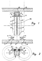
- FIG. 1 shows a schematic representation of the essential elements in the plan a device according to the invention for processing a continuous film tube FS for the production of filled tubular bags with a pair of tools.
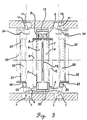
- FIG. 3 shows a device according to the same schematic representation Invention using a duo drive in which the drives are axially parallel are arranged
- the drive shafts 1 are with the drives shown schematically as box 2 assigned to a stationary housing 3 or a housing frame.
- the tool carriers 5 are connected to the drives 2 at an angle-rigid.
- the actual tools 6 are supported on the tool carriers 5 the springs 7 attached.
- the tool carriers 5 are rotatably mounted in the heads of the levers 4 and with Elements that cause a backward movement, so that the Tool carrier 5 and thus also the tools 6 always have a parallel spatial position take in.
- Carriers 8 are fastened to the free end of the tool carrier 5.
- the carrier 8 hold the Support bodies 9 designed as rollers.
- the rollers 9 are rotatably mounted such that they engage behind the side wall of the guide 10 when the tools 6 are closed.
- This guide 10 is designed as a U-shaped profile and is connected in a stationary manner to the housing 3 and thus held angularly rigid to the drive 2 and the tool holder 5.
- the Guide 10 has a clear width that is larger than the diameter of the two Support rollers 9.
- Both the attachment of the carrier 8 on the housing, and that of the support rollers 9 and the guide 10 can be adjusted to the height and depth with suitable adjusting elements Necessities of processing and guiding the tools 6 can be adapted.
- Fig. 2 shows in elevation the carrier 8 with the support rollers 9 shortly before closing the tools 6 and thus just before the support rollers 9 engage with the Guide 10.
- the side wall 11 of the guide 10 has curved on the inside Contours on which the support rollers 9 during the closing movement of the tools 6 Plant come.
- FIG. 3 shows the device according to the invention when used in a duo system, in which two opposing pairs of tools are used.
- the one pair of tools is in the operating position shown in FIG. 1.
- the second Tool pair is in the open position.
- the labels for this second Tool pair are identical, but increased by 20.
Landscapes
- Engineering & Computer Science (AREA)
- Mechanical Engineering (AREA)
- Making Paper Articles (AREA)
Abstract
Description
Claims (6)
- Einrichtung zur Herstellung von Schlauchbeuteln oder dgl. vorzugsweise aus Folien, unter Verwendung von Siegel - Werkzeugpaaren, die unter Einschluss der Folie gegeneinander gedrückt, während der Bearbeitungsdauer mit der durchlaufenden Folie synchron bewegt und nach der Bearbeitung entsprechendend dem Abstand der Bearbeitungsstellen, auf das durchlaufende Material zurückgesetzt werden, wobei die Werkzeugträger fliegend über kurbelartige Hebel auf Antriebswellen gelagert sind, dadurch gekennzeichnet, dass die freien Enden der Werkzeugträger (5) beim Durchlauf im Bearbeitungsbereich mit ortsfesten Führungen (10) in Eingriff kommen, an denen sie sich gegen die Druckkraft des Werkzeuges (6) abstützen.
- Einrichtung nach Anspruch 1, dadurch gekennzeichnet, dass am Werkzeug (6) oder dessen Halter (8) als Stützkörper, Rollen (9) angeordnet sind, die beim Durchlauf der Werkzeuge (6) im Bearbeitungsbereich, die Führungen (10) hintergreifen.
- Einrichtung nach Anspruch 1 und 2, dadurch gekennzeichnet, dass die Fläche der Führungen (10) mit einer in Pressrichtung wirksamen Konturwölbung versehen ist.
- Einrichtung nach Anspruch 1 - 3, dadurch gekennzeichnet, dass die Stützrollen (9) und/oder die Führungen (10) gegenüber den Werkzeugträgern (5) einstellbar (justierbar) befestigt sind.
- Einrichtung nach Anspruch 1 - 4, dadurch gekennzeichnet, dass die Führungen (10) für ein Werkzeugpaar durch ein U - Profil gebildet sind, dessen lichte Weite grösser ist, als der Durchmesser der Stützrollen (9).
- Einrichtung nach Anspruch 1 - 5, dadurch gekennzeichnet, dass bei Einsatz von zwei gegenüber liegenden Werkzeugpaaren (6,26) jedem der Werkzeugpaare eine ortsfeste Führung (10,30) und den Werkzeugpaaren (6,26) angepasste Stützrollen (9,29) zugeordnet sind.
Applications Claiming Priority (2)
| Application Number | Priority Date | Filing Date | Title |
|---|---|---|---|
| DE20010063U | 2000-06-05 | ||
| DE20010063U DE20010063U1 (de) | 2000-06-05 | 2000-06-05 | Einrichtung zum Bearbeiten von kontinuierlich durchlaufendem Material |
Publications (3)
| Publication Number | Publication Date |
|---|---|
| EP1162147A2 true EP1162147A2 (de) | 2001-12-12 |
| EP1162147A3 EP1162147A3 (de) | 2002-04-03 |
| EP1162147B1 EP1162147B1 (de) | 2003-12-10 |
Family
ID=7942481
Family Applications (1)
| Application Number | Title | Priority Date | Filing Date |
|---|---|---|---|
| EP01112452A Expired - Lifetime EP1162147B1 (de) | 2000-06-05 | 2001-05-22 | Einrichtung zur Herstellung von Schlauchbeuteln oder dgl |
Country Status (3)
| Country | Link |
|---|---|
| EP (1) | EP1162147B1 (de) |
| DE (2) | DE20010063U1 (de) |
| ES (1) | ES2213079T3 (de) |
Citations (1)
| Publication number | Priority date | Publication date | Assignee | Title |
|---|---|---|---|---|
| FR2446172A1 (fr) | 1979-01-10 | 1980-08-08 | Tetra Pak Int | Machine a confectionner des emballages |
Family Cites Families (4)
| Publication number | Priority date | Publication date | Assignee | Title |
|---|---|---|---|---|
| US3522135A (en) * | 1968-04-29 | 1970-07-28 | Fmc Corp | Rotating heat sealing head with cooling means |
| DE19624957A1 (de) * | 1996-06-24 | 1998-01-02 | Mark W Merritt | Einrichtung zum Antreiben und/oder Führen eines zweiteiligen Werkzeuges |
| JP3902631B2 (ja) * | 1997-04-25 | 2007-04-11 | 株式会社川島製作所 | 製袋充填包装機におけるエンドシール時間の制御方法 |
| DE29822122U1 (de) * | 1998-12-11 | 2000-04-20 | Vision Verpackungstechnik GmbH, 35305 Grünberg | Einrichtung zum Bearbeiten von kontinuierlich durchlaufendem Material |
-
2000
- 2000-06-05 DE DE20010063U patent/DE20010063U1/de not_active Expired - Lifetime
-
2001
- 2001-05-22 DE DE50101110T patent/DE50101110D1/de not_active Expired - Lifetime
- 2001-05-22 EP EP01112452A patent/EP1162147B1/de not_active Expired - Lifetime
- 2001-05-22 ES ES01112452T patent/ES2213079T3/es not_active Expired - Lifetime
Patent Citations (1)
| Publication number | Priority date | Publication date | Assignee | Title |
|---|---|---|---|---|
| FR2446172A1 (fr) | 1979-01-10 | 1980-08-08 | Tetra Pak Int | Machine a confectionner des emballages |
Also Published As
| Publication number | Publication date |
|---|---|
| DE50101110D1 (de) | 2004-01-22 |
| ES2213079T3 (es) | 2004-08-16 |
| EP1162147A3 (de) | 2002-04-03 |
| DE20010063U1 (de) | 2001-10-18 |
| EP1162147B1 (de) | 2003-12-10 |
Similar Documents
| Publication | Publication Date | Title |
|---|---|---|
| EP0226693B1 (de) | Verpackungsmaschine zum Herstellen, Füllen und Verschliessen von Beuteln | |
| DE69737826T2 (de) | Siegelmechanismus für eine Maschine zum Herstellen, Befüllen und Siegeln von Verpackungen | |
| DE2140088A1 (de) | Antriebssystem fur eine Bahnver arbeitungsvorrichtung | |
| EP1008525B1 (de) | Einrichtung zum Bearbeiten von kontinuierlich durchlaufendem Material | |
| DE102014221353A1 (de) | Schweißbacken für eine Verpackungsmaschine | |
| DE2507449A1 (de) | Maschinenschere | |
| DE1429015B2 (de) | Vorrichtung zum ausschneiden von teilstuecken aus einer folie aus kunststoff | |
| DE102017121572B4 (de) | Vorrichtung zum Herstellen von Schlauchbeuteln | |
| DE3009328A1 (de) | Maschine zum verschliessen von mit hoher geschwindigkeit in gerader linie gefuehrten behaeltern | |
| DE1586093B2 (de) | Vorrichtung zum aufbringen von aufreisstreifen auf ein einschlagmaterialband | |
| EP1162147B1 (de) | Einrichtung zur Herstellung von Schlauchbeuteln oder dgl | |
| DE3145599C2 (de) | Lederspaltmaschine | |
| DE1460183C3 (de) | Vorrichtung zum Einbringen ölimprägnierter Fasern in Gleitlager | |
| DE1197802B (de) | Vorrichtung zum Regeln der Vorspannung des Huellstoffs in Verpackungsmaschinen | |
| DE2012361B1 (de) | Kreismesserschneidemaschine | |
| EP0409151B1 (de) | Vorrichtung zum Zuführen und Vorschieben von Bandmaterial in eine Exzenterpresse | |
| EP1981792B1 (de) | Vorrichtung zum bearbeiten einer materialbahn | |
| DE1552622B2 (de) | Fliegende Schere | |
| DE1270478B (de) | Einrichtung zum Quersiegeln und Trennen eines Einwicklerschlauches an einer kontinuierlich arbeitenden Einwickelmaschine | |
| DE2224726A1 (de) | Vorrichtung zum Verschließen, Verschweißen und/oder Schneiden für horizontale oder vertikale Verpackungsmaschinen im allgemeinen | |
| DE1429015C (de) | Vorrichtung zum Ausschneiden von Teilstücken aus einer Folie aus Kunststoff | |
| DE912654C (de) | Vorrichtung zum Fuellen und Beziehen von Matratzen, Polsterkissen od. dgl. | |
| EP1340687A2 (de) | Einrichtung zum Herstellen schlauchförmiger Beutel | |
| DE2345378C3 (de) | Vorrichtung zum Ultraschallschweißen | |
| DE20022390U1 (de) | Schaumschwamm-Schneidevorrichtung mit vertikalen und horizontalen Schneideeinrichtungen |
Legal Events
| Date | Code | Title | Description |
|---|---|---|---|
| PUAI | Public reference made under article 153(3) epc to a published international application that has entered the european phase |
Free format text: ORIGINAL CODE: 0009012 |
|
| AK | Designated contracting states |
Kind code of ref document: A2 Designated state(s): DE ES FR GB IT NL Kind code of ref document: A2 Designated state(s): AT BE CH CY DE DK ES FI FR GB GR IE IT LI LU MC NL PT SE TR |
|
| AX | Request for extension of the european patent |
Free format text: AL;LT;LV;MK;RO;SI |
|
| PUAL | Search report despatched |
Free format text: ORIGINAL CODE: 0009013 |
|
| AK | Designated contracting states |
Kind code of ref document: A3 Designated state(s): AT BE CH CY DE DK ES FI FR GB GR IE IT LI LU MC NL PT SE TR |
|
| AX | Request for extension of the european patent |
Free format text: AL;LT;LV;MK;RO;SI |
|
| 17P | Request for examination filed |
Effective date: 20020412 |
|
| GRAH | Despatch of communication of intention to grant a patent |
Free format text: ORIGINAL CODE: EPIDOS IGRA |
|
| AKX | Designation fees paid |
Free format text: DE ES FR GB IT NL |
|
| GRAH | Despatch of communication of intention to grant a patent |
Free format text: ORIGINAL CODE: EPIDOS IGRA |
|
| GRAA | (expected) grant |
Free format text: ORIGINAL CODE: 0009210 |
|
| RAP1 | Party data changed (applicant data changed or rights of an application transferred) |
Owner name: MASEK-BALICI A ZPRACOVATELSKE STROJE |
|
| AK | Designated contracting states |
Kind code of ref document: B1 Designated state(s): DE ES FR GB IT NL |
|
| REG | Reference to a national code |
Ref country code: GB Ref legal event code: FG4D Free format text: NOT ENGLISH |
|
| REG | Reference to a national code |
Ref country code: IE Ref legal event code: FG4D Free format text: GERMAN |
|
| REF | Corresponds to: |
Ref document number: 50101110 Country of ref document: DE Date of ref document: 20040122 Kind code of ref document: P |
|
| GBT | Gb: translation of ep patent filed (gb section 77(6)(a)/1977) |
Effective date: 20040318 |
|
| REG | Reference to a national code |
Ref country code: IE Ref legal event code: FD4D |
|
| ET | Fr: translation filed | ||
| REG | Reference to a national code |
Ref country code: ES Ref legal event code: FG2A Ref document number: 2213079 Country of ref document: ES Kind code of ref document: T3 |
|
| PLBE | No opposition filed within time limit |
Free format text: ORIGINAL CODE: 0009261 |
|
| STAA | Information on the status of an ep patent application or granted ep patent |
Free format text: STATUS: NO OPPOSITION FILED WITHIN TIME LIMIT |
|
| 26N | No opposition filed |
Effective date: 20040913 |
|
| PGFP | Annual fee paid to national office [announced via postgrant information from national office to epo] |
Ref country code: NL Payment date: 20120531 Year of fee payment: 12 |
|
| PGFP | Annual fee paid to national office [announced via postgrant information from national office to epo] |
Ref country code: FR Payment date: 20120601 Year of fee payment: 12 Ref country code: GB Payment date: 20120522 Year of fee payment: 12 |
|
| PGFP | Annual fee paid to national office [announced via postgrant information from national office to epo] |
Ref country code: IT Payment date: 20120528 Year of fee payment: 12 |
|
| PGFP | Annual fee paid to national office [announced via postgrant information from national office to epo] |
Ref country code: ES Payment date: 20120525 Year of fee payment: 12 |
|
| REG | Reference to a national code |
Ref country code: NL Ref legal event code: V1 Effective date: 20131201 |
|
| GBPC | Gb: european patent ceased through non-payment of renewal fee |
Effective date: 20130522 |
|
| PG25 | Lapsed in a contracting state [announced via postgrant information from national office to epo] |
Ref country code: NL Free format text: LAPSE BECAUSE OF NON-PAYMENT OF DUE FEES Effective date: 20131201 Ref country code: IT Free format text: LAPSE BECAUSE OF NON-PAYMENT OF DUE FEES Effective date: 20130522 |
|
| REG | Reference to a national code |
Ref country code: FR Ref legal event code: ST Effective date: 20140131 |
|
| PG25 | Lapsed in a contracting state [announced via postgrant information from national office to epo] |
Ref country code: GB Free format text: LAPSE BECAUSE OF NON-PAYMENT OF DUE FEES Effective date: 20130522 |
|
| PG25 | Lapsed in a contracting state [announced via postgrant information from national office to epo] |
Ref country code: FR Free format text: LAPSE BECAUSE OF NON-PAYMENT OF DUE FEES Effective date: 20130531 |
|
| REG | Reference to a national code |
Ref country code: ES Ref legal event code: FD2A Effective date: 20140609 |
|
| PG25 | Lapsed in a contracting state [announced via postgrant information from national office to epo] |
Ref country code: ES Free format text: LAPSE BECAUSE OF NON-PAYMENT OF DUE FEES Effective date: 20130523 |
|
| PGFP | Annual fee paid to national office [announced via postgrant information from national office to epo] |
Ref country code: DE Payment date: 20200730 Year of fee payment: 20 |
|
| REG | Reference to a national code |
Ref country code: DE Ref legal event code: R071 Ref document number: 50101110 Country of ref document: DE |