EP1160023A2 - Karosserieausbeulvorrichtung - Google Patents
Karosserieausbeulvorrichtung Download PDFInfo
- Publication number
- EP1160023A2 EP1160023A2 EP01111898A EP01111898A EP1160023A2 EP 1160023 A2 EP1160023 A2 EP 1160023A2 EP 01111898 A EP01111898 A EP 01111898A EP 01111898 A EP01111898 A EP 01111898A EP 1160023 A2 EP1160023 A2 EP 1160023A2
- Authority
- EP
- European Patent Office
- Prior art keywords
- dent device
- attached
- body dent
- guide column
- support arm
- Prior art date
- Legal status (The legal status is an assumption and is not a legal conclusion. Google has not performed a legal analysis and makes no representation as to the accuracy of the status listed.)
- Withdrawn
Links
Images




Classifications
-
- B—PERFORMING OPERATIONS; TRANSPORTING
- B21—MECHANICAL METAL-WORKING WITHOUT ESSENTIALLY REMOVING MATERIAL; PUNCHING METAL
- B21D—WORKING OR PROCESSING OF SHEET METAL OR METAL TUBES, RODS OR PROFILES WITHOUT ESSENTIALLY REMOVING MATERIAL; PUNCHING METAL
- B21D1/00—Straightening, restoring form or removing local distortions of sheet metal or specific articles made therefrom; Stretching sheet metal combined with rolling
- B21D1/06—Removing local distortions
-
- B—PERFORMING OPERATIONS; TRANSPORTING
- B21—MECHANICAL METAL-WORKING WITHOUT ESSENTIALLY REMOVING MATERIAL; PUNCHING METAL
- B21D—WORKING OR PROCESSING OF SHEET METAL OR METAL TUBES, RODS OR PROFILES WITHOUT ESSENTIALLY REMOVING MATERIAL; PUNCHING METAL
- B21D1/00—Straightening, restoring form or removing local distortions of sheet metal or specific articles made therefrom; Stretching sheet metal combined with rolling
- B21D1/12—Straightening vehicle body parts or bodies
Definitions
- the present invention relates to a Body dent device according to the preamble of Claim 1.
- Such body bulging devices are in the prior art Technology known. They are used to remove sheet metal damage used in motor vehicles. Usually it is Body sheet over a more or less large area indented inside. A dent from the vehicle interior is impossible due to the supporting structure of the body. The Sheet metal must therefore be processed from the outside. To this end become hooks or so-called shaft wires by welding or sticking outside in the area of the pressed sheet appropriate. The hooks or shaft wires must be sufficient be attached to absorb the necessary tensile forces can to the pressed sheet approximately to the outside in withdraw its original form. The traction will via attached levers or attached to a frame Traction screws or floor pulls applied over hooks or so-called BI pullers with hooks or shaft wires are connected.
- the frame itself is held over supports, which are even supported on the surrounding body.
- the traction spindles individually dressed so that the original Sheet surface shape is restored.
- the remaining Bumps can appear after removing the device Filler be balanced so that the accident damage is no longer visible after painting.
- the supports can be used in places that are difficult to access, such as the fender area or in the front or be put on relatively badly in the rear area, since none flat or only relatively small support surfaces available stand. The same applies to dent work in the roof area. Overall, this is a very unsatisfactory condition.
- the object of the present invention is therefore in Providing a body dent device that is high Can apply tensile forces, however, a burden on the Avoids bodywork and in almost every area of the car Motor vehicle used regardless of accessibility can be.
- this task is performed by a Body dent device with the characteristic ones Features of claim 1 solved.
- a Body dent device which has at least one Includes boom with at least a portion of the Weight force of the vehicle resilient and therefore on the Soil is definable, the whole Body bulge not as before by on the Body supports held so that none Forces that cause damage in undamaged areas can be derived from the body. Instead it will the body dent by the weight of the fixed to repaired motor vehicle.
- the vehicle itself namely serves as a counterweight in the invention Support of the body dent device on the Floor area. This is done by the vehicle on the Outrigger is provided and this by the Vehicle weight fixed against the floor.
- the weight of the vehicle is advantageously by initiated the wheels on the at least one outrigger. To do this, the vehicle simply drives onto the outrigger. As a result, even higher tractive forces can be used to repair the Body initiated and overall a better one Repair result can be achieved. Even inaccessible Positions in the front, rear and roof area can be easy be dented.
- the support boom is advantageously an essentially flat sheet metal profile, which is preferred a trough in the longitudinal direction for receiving a car tire includes.
- the motor vehicle can move sideways or head-on Sheet metal is rolled or driven and comes to in the trough Stand or is secured against rolling away.
- a guide column is provided, which in is arranged substantially perpendicular to the boom.
- the guide pillar is accordingly from the body spaced and can accommodate appropriate traction.
- the vertical guide column offers a wide range of options Attachment points for traction devices.
- a boom extension also proves to be advantageous, which can also absorb forces caused by the traction means, transfer to the outrigger via the guide column become. Extended by pulling out the boom extension the lever arm of the support arm, so that higher tensile forces can be exercised.
- the Body dent removal devices are castable rollers provided on the outrigger and / or on the Boom extensions are attached. They can be jacked up Rolling through a lever attached to a roll, whereby the other role is jacked up synchronously via a linkage and the body dent on the floor surface can be rolled.
- a recording is provided, which one front cross strut can accommodate.
- this cross strut can be attached to additional guide columns with outrigger be so that the body bulge expand and optimally meet the requirements of sheet metal damage, as well as adapt to the center distance of the motor vehicle.
- a spindle is provided which is parallel to Guide column is rotatably mounted.
- a suitable spindle block and an electric motor Move the spindle block very precisely on the guide column. This characteristic is particularly important when there are several in a row arranged guide columns interesting, especially in synchronous movement of the spindle blocks.
- the spindle blocks are advantageous also provided with eyelets to accommodate traction devices.
- a turnbuckle is advantageously used as the traction means Commitment.
- Such devices can be individually between the eyelets of the spindle blocks or the sleeves and on the Body-attached means such as anchors, welded hooks or corrugated wire can be attached and according to the requirements, also individually, braced be, so that the desired success, the bulge of the pressed sheet occurs.
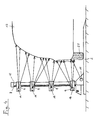
- a body dent device 1 essentially comprises two receptacles 20 connected to one another via a front cross strut 15, two vertically upwardly projecting guide columns 12, and two support arms 2 suitable for receiving a motor vehicle 13.
- the jibs 2 are essentially Tread plates that are shaped such that a tire 22nd of a motor vehicle 13 also to the Support arms 2 molded ramp can get into a trough and is secured against rolling away there.
- a stopper 3 is provided, via which the vertical spacing of the device 1 from the wheel 22 can be set and fixed. This function is among other things necessary if strong tensile forces to Bulging the body 13 must be used.
- the support boom 2 are attached to the receptacles 20, the as already indicated above, via a front cross strut 15 connected with each other. You can by solving Compression fittings are moved against each other. The Distance of the outrigger 2 can thus be individually on the Wheel base of the motor vehicle 13 can be adjusted. About that In addition, the outrigger 2 are still extendable Boom extensions 5 equipped so that a better Support is possible.
- the whole Body dent device 1 has on the bottom side attached rollers 4 by a lifting mechanism 6 are easily extendable downwards. With the lifting mechanism 6 it is a roller 4 attached to a lever, the roller 4 attached to the boom extension 5 can be lowered synchronously via a linkage, so that the Move the body dent device 1 freely on the floor can be.
- each a combination of a guide column 12 and one Spindle 8 provided by turning the spindle 8 a Spindle block 9, which is displaceable on the guide column 12 is stored, can be moved.
- the two spindle blocks 9 can be synchronized Guide column 12 are moved equally, so that the spindle blocks 9 attached rear cross member 14 in their height can be moved.
- the rear cross member 14 provides the receptacle for a number of sleeves 16, which are free on the preferably cylindrical cross member 14 can be moved.
- the Sleeves 16 are equipped with eyelets in which for example turnbuckles 10 or similar traction means can be hung.
- Corresponding damage to the pressed-in sheet Body hook 11 such as pull anchor 17, Corrugated wire 21 or welded hooks 19 attached which hooked a turnbuckle 10 or similar traction can be.
- Corrugated wire 21 comes an additional so-called BI puller to use, which in the Wire bulges can be hooked in and the pulling force equally distributed.
- the Distance of the boom 2 by moving the receptacles 20 on the front cross strut 15 according to the wheelbase can be set.
- the spindle drive 8 can also be applied a tractive force, especially at a non-perpendicular angle be used to the body surface, for example in Roof area diagonally upwards.
- FIG. 6 shows an overall perspective view of FIG Body bulging device 1 according to FIGS. 1-5, wherein the same reference numerals are used.
Landscapes
- Engineering & Computer Science (AREA)
- Mechanical Engineering (AREA)
- Tents Or Canopies (AREA)
- Vehicle Cleaning, Maintenance, Repair, Refitting, And Outriggers (AREA)
- Bridges Or Land Bridges (AREA)
- Body Structure For Vehicles (AREA)
Abstract
Description
- Fig. 1
- eine seitliche Ansicht einer erfindungsgemäßen Karosserieausbeulvorrichtung;
- Fig. 2
- eine Draufsicht auf eine erfindungsgemäße Karosserieausbeulvorrichtung;
- Fig. 3
- eine Frontansicht einer erfindungsgemäßen Karosserieausbeulvorrichtung;
- Fig. 4
- eine erfindungsgemäße Karosserieausbeulvorrichtung mit Spindelblöcken, mit schematischer Darstellung unterschiedlicher Reparaturpositionen;
- Fig. 5
- eine erfindungsgemäße Karosserieausbeulvorrichtung in einer Einsatzposition zur Reparatur von Heck- bzw. Frontschäden;
- Fig. 6
- eine perspektivische Gesamtansicht der Karosserieausbeulvorrichtung gemäß Fig. 1 - 5.
Eine erfindungsgemäße Karosserieausbeulvorrichtung 1 umfaßt im wesentlichen zwei, über eine vordere Querstrebe 15 miteinander verbundene Aufnahmen 20, zwei senkrecht empor ragende Führungssäulen 12, sowie zwei zur Aufnahme eines Kraftfahrzeugs 13 geeigneten Stützausleger 2.
Claims (21)
- Karosserieausbeulvorrichtung (1), umfassend ein mit Abstand von der Karosserie eines Kraftfahrzeugs anbringbares Gerüst (Führungssäule 12, hintere Querstreben 14), sowie Mittel (Ziehanker 17, Wellendraht 21, Haken 19), die am Karosserieblech anbringbar sind und zur Aufnahme von Zugkräften geeignet sind, sowie zwischen Gerüst (Führungssäule 12, hintere Querstreben 14) und den am Karosserieblech anbringbaren Mitteln (Ziehanker 17, Wellendraht 21, Haken 19) einhängbare Zugmittel (Spannschloss 10), dadurch gekennzeichnet, daß die Karosserieausbeulvorrichtung (1) mindestens einen Stützausleger (2) umfaßt, der mit zumindest einem Teil des Eigengewichts des Kraftfahrzeugs (13) belastbar und gegen eine Bodenfläche festlegbar ist.
- Karosserieausbeulvorrichtung nach einem der Ansprüche 1, dadurch gekennzeichnet, daß die Oberseite des Stützauslegers (2) mit seiner Unterseite auf einer Bodenfläche liegend, von dem Kraftfahrzeug (13) befahrbar ist.
- Karosserieausbeulvorrichtung nach Anspruch 1 oder 2, dadurch gekennzeichnet, daß der Stützausleger (2) eine Mulde zur sicheren Aufnahme eines Autoreifens (22) umfaßt.
- Karosserieausbeulvorrichtung nach einem der Ansprüche 1 bis 3, dadurch gekennzeichnet, daß der Stützausleger (2) als im wesentlichen flaches Blechprofil ausgebildet ist.
- Karosserieausbeulvorrichtung nach einem der Ansprüche 1 bis 4, dadurch gekennzeichnet, daß der Stützausleger (2) unten an einer senkrecht dazu stehenden Führungssäule (12) angeordnet ist.
- Karosserieausbeulvorrichtung nach einem der Ansprüche 1 bis 5, dadurch gekennzeichnet, daß der Stützausleger (2) mit einer endseitig ausziehbaren Auslegerverlängerung (5) ausgestattet ist.
- Karosserieausbeulvorrichtung nach einem der Ansprüche 1 bis 6, dadurch gekennzeichnet, daß der Stützausleger (2) mit mindestens einer wahlweise aufbockbaren Rolle (4) ausgestattet ist.
- Karosserieausbeulvorrichtung nach einem der Ansprüche 1 bis 7, dadurch gekennzeichnet, daß endseitig an der Auslegerverlängerung (5) eine Rolle (4) vorgesehen ist, die über ein Auslösegestänge zusammen mit der Rolle (4) nach unten ausgefahren werden kann.
- Karosserieausbeulvorrichtung nach einem der Ansprüche 1 bis 8, dadurch gekennzeichnet, daß an der Führungssäule (12) eine Aufnahme(20) für eine vordere Querstrebe (15) angebracht ist.
- Karosserieausbeulvorrichtung nach einem der Ansprüche 1 bis 9, dadurch gekennzeichnet, daß parallel zu der senkrechten Führungssäule (12) eine Spindel (8) drehbar gelagert ist.
- Karosserieausbeulvorrichtung nach einem der Ansprüche 1 bis 10, dadurch gekennzeichnet, daß die Spindel (8) über einen an der Führungssäule (12) angebrachten Elektromotor (7) antreibbar ist.
- Karosserieausbeulvorrichtung nach einem der Ansprüche 1 bis 11, dadurch gekennzeichnet, daß mindestens ein Spindelblock (9) vorgesehen ist, der auf der Führungssäule (12) in Längsrichtung verschiebbar ist.
- Karosserieausbeulvorrichtung nach einem der Ansprüche 1 bis 12, dadurch gekennzeichnet, daß der Spindelblock (9) über die Spindel (8) durch Drehbewegung in Längsrichtung der Führungssäule (12) verfahrbar ist.
- Karosserieausbeulvorrichtung nach einem der Ansprüche 1 bis 13, dadurch gekennzeichnet, daß der Spindelblock (9) mit einer Aufnahme für eine hintere Querstrebe (14) ausgestattet ist.
- Karosserieausbeulvorrichtung nach einem der Ansprüche 1 bis 14, dadurch gekennzeichnet, daß mindestens zwei Einheiten aus jeweils mindestens einem Stützausleger (2) einer Aufnahme (20) und mindestens einer Führungssäule (12) über mindestens eine vordere Querstrebe (15) nebeneinender angeordnet und fixiert werden können.
- Karosserieausbeulvorrichtung nach einem der Ansprüche 1 bis 15, dadurch gekennzeichnet, daß mindestens ein Spindelblock (9) mit einem weiteren Spindelblock (9) über eine hinter Querstrebe (14) verbunden werden kann.
- Karosserieausbeulvorrichtung nach einem der Ansprüche 1 bis 16, dadurch gekennzeichnet, daß Muffen (16) auf mindestens einer vorderen Querstrebe (15) und / oder mindestens einer hinteren Querstrebe (14) vorgesehen sind, die mit Ösen zur Aufnahme von Zugmitteln (Spannschloss 10) ausgestattet sind.
- Karosserieausbeulvorrichtung nach einem der Ansprüche 1 bis 17, dadurch gekennzeichnet, daß die Muffen (16) verschiebbar auf den Querträgern (14, 15) gelagert sind.
- Karosserieausbeulvorrichtung nach einem der Ansprüche 1 bis 18, dadurch gekennzeichnet, daß der Spindelblock (9) mit mindestens einer Öse zur Aufnahme eines Zugmittels (Spannschloss 10) ausgestattet ist.
- Karosserieausbeulvorrichtung nach einem der Ansprüche 1 bis 19, dadurch gekennzeichnet, daß es sich bei den Zugmitteln um mindestens ein Spannschloss (10) handelt.
- Karosserieausbeulvorrichtung nach einem der Ansprüche 1 bis 20, dadurch gekennzeichnet, daß es sich bei den Mitteln, die an der Karosserie (13) anbringbar sind und zur Aufnahme von Zugkräften geeignet sind, wahlweise um Ziehanker (17), um angeschweißte Haken (19) oder um Wellendraht (21) handelt.
Applications Claiming Priority (2)
| Application Number | Priority Date | Filing Date | Title |
|---|---|---|---|
| DE2000126617 DE10026617C1 (de) | 2000-05-29 | 2000-05-29 | Karosserieausbeulvorrichtung |
| DE10026617 | 2000-05-29 |
Publications (2)
| Publication Number | Publication Date |
|---|---|
| EP1160023A2 true EP1160023A2 (de) | 2001-12-05 |
| EP1160023A3 EP1160023A3 (de) | 2003-11-19 |
Family
ID=7643988
Family Applications (1)
| Application Number | Title | Priority Date | Filing Date |
|---|---|---|---|
| EP01111898A Withdrawn EP1160023A3 (de) | 2000-05-29 | 2001-05-17 | Karosserieausbeulvorrichtung |
Country Status (2)
| Country | Link |
|---|---|
| EP (1) | EP1160023A3 (de) |
| DE (1) | DE10026617C1 (de) |
Cited By (5)
| Publication number | Priority date | Publication date | Assignee | Title |
|---|---|---|---|---|
| CN110369554A (zh) * | 2019-08-02 | 2019-10-25 | 深圳南方中集集装箱服务有限公司 | 集装箱前端校正机 |
| CN110918692A (zh) * | 2019-12-26 | 2020-03-27 | 江门市保值久机电有限公司 | 汽车钣金修复器的辅助支撑架 |
| JP2020152366A (ja) * | 2019-03-18 | 2020-09-24 | 株式会社エス企画 | 自動車ボデー修復装置 |
| CN114247772A (zh) * | 2020-09-23 | 2022-03-29 | 本田技研工业株式会社 | 调整夹具以及调整方法 |
| US11654467B2 (en) * | 2019-04-14 | 2023-05-23 | Mark Jackson | Automobile dent puller apparatus and method |
Families Citing this family (1)
| Publication number | Priority date | Publication date | Assignee | Title |
|---|---|---|---|---|
| US9457391B2 (en) * | 2014-05-16 | 2016-10-04 | Lockheed Martin Corporation | Apparatus and method for deforming a surface |
Family Cites Families (8)
| Publication number | Priority date | Publication date | Assignee | Title |
|---|---|---|---|---|
| DE1600246B1 (de) * | 1966-12-08 | 1970-01-15 | Applied Power Ind Inc | Zugklemme zum Strecken von Blechteilen,insbesondere zum Richten von z.B. durch Anprall versetzten Fahrzeugrahmen oder Karosserien |
| FR2148332B1 (de) * | 1971-08-06 | 1974-12-13 | Facom | |
| SE426214C (sv) * | 1978-02-08 | 1991-07-08 | Nordsvets Kemppi Ab | Anordning foer fastsvetsning av dragtraad |
| US4296626A (en) * | 1979-06-21 | 1981-10-27 | Jarman Davis R | Wheel alignment apparatus |
| US4802358A (en) * | 1987-07-10 | 1989-02-07 | Andrew A. Bucci | Vehicle repair apparatus |
| GB2240737B (en) * | 1990-02-08 | 1994-05-25 | Thomas Rodgers | Pulling apparatus |
| DE9411199U1 (de) * | 1994-07-11 | 1995-02-16 | Birkner, Thomas, 70469 Stuttgart | Montier- u. Ausbeulständer |
| FI96284C (fi) * | 1994-09-12 | 1996-06-10 | Autorobot Finland | Autonkorin oikaisulaite ja menetelmä autonkorin oikaisutyössä |
-
2000
- 2000-05-29 DE DE2000126617 patent/DE10026617C1/de not_active Expired - Fee Related
-
2001
- 2001-05-17 EP EP01111898A patent/EP1160023A3/de not_active Withdrawn
Cited By (7)
| Publication number | Priority date | Publication date | Assignee | Title |
|---|---|---|---|---|
| JP2020152366A (ja) * | 2019-03-18 | 2020-09-24 | 株式会社エス企画 | 自動車ボデー修復装置 |
| US11654467B2 (en) * | 2019-04-14 | 2023-05-23 | Mark Jackson | Automobile dent puller apparatus and method |
| US11738381B2 (en) * | 2019-04-14 | 2023-08-29 | Mark Jackson | Automobile dent puller apparatus and method |
| CN110369554A (zh) * | 2019-08-02 | 2019-10-25 | 深圳南方中集集装箱服务有限公司 | 集装箱前端校正机 |
| CN110918692A (zh) * | 2019-12-26 | 2020-03-27 | 江门市保值久机电有限公司 | 汽车钣金修复器的辅助支撑架 |
| CN114247772A (zh) * | 2020-09-23 | 2022-03-29 | 本田技研工业株式会社 | 调整夹具以及调整方法 |
| CN114247772B (zh) * | 2020-09-23 | 2024-03-12 | 本田技研工业株式会社 | 调整夹具以及调整方法 |
Also Published As
| Publication number | Publication date |
|---|---|
| EP1160023A3 (de) | 2003-11-19 |
| DE10026617C1 (de) | 2001-11-08 |
Similar Documents
| Publication | Publication Date | Title |
|---|---|---|
| DE60020561T2 (de) | Tragvorrichtung für fahrzeugrädern | |
| DE2261430C3 (de) | Vorrichtung zum Kippen eines Kraftfahrzeugs und Verfahren zu ihrem Betrieb | |
| DE8911634U1 (de) | In Teilen transportierbares Vergnügungsgerät für Jahrmärkte od.dgl., insbesondere Riesenrad | |
| DE19731324A1 (de) | Ausziehbarer Ladeboden für ein Fahrzeug | |
| EP0887300A2 (de) | Hub-Dreh-Vorrichtung zur Aufnahme eines Kraftfahrzeuges | |
| DE10026617C1 (de) | Karosserieausbeulvorrichtung | |
| EP3285977A1 (de) | Vorrichtung zum einbau einer windschutzscheibe eines fahrzeug | |
| CH660895A5 (de) | Vorrichtung zum setzen von pfosten, pfaehlen oder schneestangen. | |
| DE2633683C2 (de) | Transportfahrzeug für Fertiggaragen und dergleichen | |
| DE10105701C2 (de) | Hub- und Senkeinrichtung für einen Autotransporter und einen Autotransport-Anhänger | |
| DE4302421C2 (de) | Zweistöckige Parkeinrichtung | |
| DE2825130C3 (de) | Ersatzrad-Halterung für Lastfahrzeuge | |
| DE2028564B2 (de) | Abstellvorrichtung für zwei Kraftfahrzeuge übereinander | |
| DE2411566C3 (de) | Vorrichtung zum Richten von Fahrzeugrahmen o.dgl | |
| EP1366971B1 (de) | Sattelzugmaschine | |
| EP3120969A1 (de) | Mobile achsenpresse | |
| DE3232899C2 (de) | ||
| EP3670427A1 (de) | Unterflurhebevorrichtung | |
| DE102024107076B4 (de) | Fahrzeugträger für einen Prüfstand und Verfahren zur Rüstung eines Prüfstandes mit einem derartigen Fahrzeugträger | |
| DE1031726B (de) | Vorrichtung fuer Fahrzeuge, insbesondere Kraftfahrzeuge zum Tragen eines fahrbaren Behaelters auf der Ladeflaeche | |
| AT411666B (de) | Verfahren zum abnehmen und abstellen eines auswechselbaren aufbaus vom chassis eines lastkraftwagens und lastkraftwagen mit einem auswechselbaren aufbau | |
| DE102011103245B4 (de) | Sitzvorrichtung für eine Fahrzeugfertigungslinie, umfassend einen Sitzarm mit einem Sitzelement und einen Hilfsarm mit einer Einrichtung zur Aufnahme von Arbeitsmitteln und/oder Werkzeugen | |
| DE3207949C2 (de) | Einrichtung zum Setzen von Streckenausbaurahmen im untertägigen Bergbau | |
| DE3829795C1 (en) | Supporting device for lifting vehicles under the wheels | |
| DE10213719B4 (de) | Reparaturbühne für Kraftfahrzeuge |
Legal Events
| Date | Code | Title | Description |
|---|---|---|---|
| PUAI | Public reference made under article 153(3) epc to a published international application that has entered the european phase |
Free format text: ORIGINAL CODE: 0009012 |
|
| AK | Designated contracting states |
Kind code of ref document: A2 Designated state(s): AT BE CH CY DE DK ES FI FR GB GR IE IT LI LU MC NL PT SE TR |
|
| AX | Request for extension of the european patent |
Free format text: AL;LT;LV;MK;RO;SI |
|
| PUAL | Search report despatched |
Free format text: ORIGINAL CODE: 0009013 |
|
| AK | Designated contracting states |
Kind code of ref document: A3 Designated state(s): AT BE CH CY DE DK ES FI FR GB GR IE IT LI LU MC NL PT SE TR |
|
| AX | Request for extension of the european patent |
Extension state: AL LT LV MK RO SI |
|
| STAA | Information on the status of an ep patent application or granted ep patent |
Free format text: STATUS: THE APPLICATION IS DEEMED TO BE WITHDRAWN |
|
| 18D | Application deemed to be withdrawn |
Effective date: 20031202 |