EP1159909A1 - Shower booth - Google Patents
Shower booth Download PDFInfo
- Publication number
- EP1159909A1 EP1159909A1 EP01401403A EP01401403A EP1159909A1 EP 1159909 A1 EP1159909 A1 EP 1159909A1 EP 01401403 A EP01401403 A EP 01401403A EP 01401403 A EP01401403 A EP 01401403A EP 1159909 A1 EP1159909 A1 EP 1159909A1
- Authority
- EP
- European Patent Office
- Prior art keywords
- shower
- cabin
- wall
- receiver
- panel
- Prior art date
- Legal status (The legal status is an assumption and is not a legal conclusion. Google has not performed a legal analysis and makes no representation as to the accuracy of the status listed.)
- Withdrawn
Links
Images


Classifications
-
- A—HUMAN NECESSITIES
- A47—FURNITURE; DOMESTIC ARTICLES OR APPLIANCES; COFFEE MILLS; SPICE MILLS; SUCTION CLEANERS IN GENERAL
- A47K—SANITARY EQUIPMENT NOT OTHERWISE PROVIDED FOR; TOILET ACCESSORIES
- A47K3/00—Baths; Douches; Appurtenances therefor
- A47K3/28—Showers or bathing douches
- A47K3/283—Fixed showers
- A47K3/284—Pre-fabricated shower cabinets
Definitions
- the present invention relates to a shower cubicle, and aims in particular such a cabin capable of receiving not only standard taps but also various equipment, for example a hydrotherapy massage system.
- a usual drawback of existing shower stalls is to require, for their maintenance, disassembly often causing deterioration of the cabin environment (tiling, furniture) to allow access to the various equipment of this cabin, in particular of the taps.
- the object of the invention is precisely to propose a shower cabin which allows convenient and economical servicing and maintenance, and allows in particular access to organs and equipment to be repaired or replaced without it be necessary to deteriorate the cabin environment.
- Another object of the invention consists in proposing a shower cabin which, in the case of complex equipment in particular, authorizes the adjustment thereof without the user having to enter the cabin.
- the invention provides a shower enclosure comprising: a receiver or tray intended to receive the water from the shower and connected to a drain of this water; and surrounding this receiver, a bottom wall carrying the cabin equipment as well a shower wall comprising or constituting the entrance door to this cabin, characterized in that it comprises at least one strip receiving one or more showers, the strip being arranged on the bottom wall and removable from the inside from the cabin.
- the bottom wall and the shower wall each constitute a autonomous element, these elements being equipped with mutual assembly means as well as means of connection with the receiver.
- the assembly means are accessible from outside the assembled cabin and, from preferably allow disassembly of the shower wall from the bottom wall by access to the assembly means from the side corresponding to the wall of shower.
- the bottom wall consists of a central panel or corner panel which is flanked by two side panels and is permanently attached thereto, the strip being arranged on one of the panels lateral.
- the central panel or corner panel be fixed to the two side panels permanently but removable from preferably from inside the assembled cabin. Thanks to this arrangement, it is possible, if necessary, to disassemble the walls from one another without having to move the shower tray without damaging the cabin environment.
- the side panel on which the strip (42) is arranged can present a niche receiving the banner.
- Another banner receiving one or more showers can be advantageously arranged on the other side panels.
- the receiver presents on a part at least from its upper edge a rib, while a groove of the part bottom of a cross member is capable of covering said rib, this cross member constituting the lower edge of the shower screen.
- the crosspiece is joined by a end to one face of a post fixed along a rim of the side panel adjacent, by means of screws accessible from outside the cabin.
- one or more pieces of equipment the cabin are adapted to be controlled remotely by means of a remote control, preferably of the infrared type.
- a remote control preferably of the infrared type.
- This preferred embodiment can also be implemented independently on shower enclosures that do not have some or all of the features of the invention mentioned above. It is particularly advantageous that the remote control makes it possible to control this or these equipment (s) from outside the assembled shower enclosure.
- Figure 9 is a sectional view showing the assembly of the side panel on the receiver.
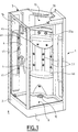
- the shower cabin 1 comprises: at its base a receiver or tray 2 forming a base; a wall of bottom 3 (see Figure 4) consisting of several panels as we will see better below, and on which the cabin equipment is fixed; and a wall of shower 4 usually allowing access to the cabin.
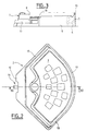
- Receiver 2 an embodiment of which is shown in detail in Figures 2 and 3, is preferably made in one piece, for example by means a thermoformed skin 5 and an inner reinforcement of expanded polystyrene 6 (see figure 3).
- Other manufacturing techniques are obviously possible: composite (glass fiber reinforced resin, thermoformed skin reinforced with glass fibers, etc.)
- the outer contour of the receiver can have any polygonal shape or other (for example be in the shape of a square, pentagon, quarter of a circle) according to the configuration of the room to be equipped.
- the receiver 2 naturally has the function of draining the water which flows on the bottom and shower walls, and it forms for this purpose on a base 7 resting on the floor 8, a bowl 9 in which is mounted a drain 10 for water from runoff, connected to the drain pipe 11.
- the receiver is designed so that the drain can be connected when it is in place and has a cutaway 12 on its rear part allowing free access to the connection.
- a peripheral rib 13, formed on an upper edge part of the receiver is intended to receive as will be seen below the lower edge of the panels.
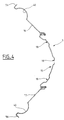
- the bottom wall 3 a horizontal section of which is shown in FIG. 4, is here composed of a central panel 15 flanked by two symmetrical side panels.
- the central panel 15 or corner panel, facing an angle of the room to equip, has a curvilinear section whose concavity is turned inward of the cabin and which here includes recesses 18 intended in particular for mounting of the accessories 22 (in particular the taps 22a) indicated in FIG. 1.
- the central panel 15 For its removable assembly to each of the side panels 16, 17, of which the detail is represented in FIG. 5 for the panel 17, the central panel 15 has on each of its vertical edges a tuck-in fold 19, which is extended by a angled elbow having two branches 20 and 21, orthogonal. This last branch 21, which constitutes a free edge of the central panel 15, is parallel to the vertical plane of symmetry of the shower cabin.
- the free edge of the side panel 17 has a re-entrant fold 23 parallel, in the assembly position, to the branch 21 of the panel 15 extended by a angled elbow having two orthogonal branches 24, 25, the branch 24, adjacent at the fold 23, being parallel, in the assembly position, to the branch 20.
- the branch 20 of the panel 15 and the branch 24 of the panel 17 are drilled with holes 28, 29, respectively, corresponding two by two for the screw passage 30.
- each side panel 16, 17 has, opposite its region assembly to the central panel, a flange 56 intended, as will be seen below, the fixing of the bottom wall to the shower wall.
- each side panel 16, 17, has a niche 40, intended to receive, if necessary, side showers 41 hydromassage for example.
- each niche 40 is equipped with a strip 42, which receives the showers and is fixed, for example in the upper and lower parts of the niche, by means of self-tapping screws 43. These strips 42 are thus removable from inside the cabin and allow convenient access to a possibly defective equipment.
- Shelves 45 can advantageously be provided during the preparation side panels 16, 17. Likewise, shelves or a bench seat 46 may be provided during the manufacture of the bottom panel 15.
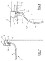
- Figure 7 illustrates the mounting of a shower screen (not shown) on the receiver 2.
- the rib 13 receives a profile 50 or crosspiece, which covers it with a groove 51 of its lower part.
- a housing 52, intended to receive a window with its seal is provided at the upper part of this profile 50. This arrangement allows a assembly on the receiver 2 without adding sealant.
- Figure 8 shows the junction of the shower wall 4 with a side panel 17 of the bottom wall of the cabin according to the invention.
- the cross member 50 is joined to its end 53 to a post 54 also consisting of a cross-section profile U-shaped, which is fixed by means of screws 55 for example, along a edge 56 of side panel 16 or 17 (see Figures 4, 6 and 8), through the bottom of the U.
- This upright 54 is fixed to the cross-member 50 by any appropriate means, for example screws 57 passing through a U-shaped upright and entering appropriate housings 58 of the cross member 50 ( Figure 7).
- An adjustable finishing strip 60 is clipped onto the upright 54 and extends to the wall of the room. The removal of this wand provides access to the fixing screws 55 on the side panel, without moving the cabin.
- the configuration of the profile or upright 54 ensures a seal without joint or sealant: for this a rib 61 is formed on the bottom of the U-shaped profile 54, this rib 61 covering the edge of the side panel 16 or 17 provided with a chamfer and thus constituting with the chamfer of the panel a passage in baffle 62.
- the arrow 64 indicates the path of the water in the groove dug in the catcher (see Figure 2).
- Figure 9 shows how water that could seep under or behind the bottom panels is stopped by the ledge and channeled into the recovery groove opening into the receiver tray on the edges of the side panels.
- a cap 70 ( Figure 1). This cap, made by thermoforming or any other technique, is also removable from inside the cabin, without movement of the receiver 2.
- a remote control for example an infrared remote control adapted in particular to control the various functions used in an installation or system hydromassage.
- a remote control allows in particular the preheating of the shower and start-up of the hammam from outside the cabin. She permits also easier use, in a seated position, of the hydromassage system.
- a remote control system can be provided for any type of shower cubicles regardless of the structure of the panels and the shower tray and assembly means described above.
Landscapes
- Health & Medical Sciences (AREA)
- Public Health (AREA)
- Epidemiology (AREA)
- General Health & Medical Sciences (AREA)
- Bathtubs, Showers, And Their Attachments (AREA)
- Residential Or Office Buildings (AREA)
Abstract
Description
La présente invention se rapporte à une cabine de douche, et vise notamment une telle cabine apte à recevoir non seulement une robinetterie usuelle mais aussi divers équipements, par exemple un système de massage par hydrothérapie.The present invention relates to a shower cubicle, and aims in particular such a cabin capable of receiving not only standard taps but also various equipment, for example a hydrotherapy massage system.
Un inconvénient habituel des cabines de douche existantes est de nécessiter, pour leur entretien, un démontage entraínant souvent la détérioration de l'environnement de la cabine (carrelage, meuble) pour permettre l'accès aux divers équipements de cette cabine, en particulier de la robinetterie.A usual drawback of existing shower stalls is to require, for their maintenance, disassembly often causing deterioration of the cabin environment (tiling, furniture) to allow access to the various equipment of this cabin, in particular of the taps.
Un autre inconvénient réside dans l'utilisation de mastic type silicone ou autre pour assurer l'étanchéité entre paroi de douche et receveur et entre panneaux de fond. Cette cabine en outre est conçue de telle façon qu'aucun mastic n'est utilisé pour l'étanchéité entre les différents éléments, et donc de supprimer :
- le problème de pose du mastic (très délicat) ;
- le vieillissement du mastic dans le temps (noircissement, décollement, fuites ...) ;
- the problem of fitting the putty (very delicate);
- aging of the sealant over time (blackening, detachment, leaks ...);
Dans le cas des cabines de douche comportant des équipements relativement complexes et nécessitant des réglages de la température de l'eau et des divers débits, ces réglages s'effectuent habituellement de l'intérieur de la cabine, ce qui ne va pas sans inconvénients pour l'utilisateur.In the case of shower enclosures with relatively equipment complex and requiring adjustments of the water temperature and the various flow rates, these adjustments are usually made from inside the cabin, which is not without disadvantages for the user.
L'objet de l'invention est précisément de proposer une cabine de douche qui permette un entretien et une maintenance commodes et économiques, et autorise notamment un accès aux organes et équipements à réparer ou remplacer sans qu'il soit nécessaire de détériorer l'environnement de la cabine.The object of the invention is precisely to propose a shower cabin which allows convenient and economical servicing and maintenance, and allows in particular access to organs and equipment to be repaired or replaced without it be necessary to deteriorate the cabin environment.
Un autre objet de l'invention consiste à proposer une cabine de douche qui, dans le cas d'équipements complexes en particulier, autorise le réglage de ceux-ci sans que l'utilisateur ne doive pénétrer dans la cabine.Another object of the invention consists in proposing a shower cabin which, in the case of complex equipment in particular, authorizes the adjustment thereof without the user having to enter the cabin.
Ainsi, l'invention propose une cabine de douche comprenant : un receveur ou bac destiné à recevoir l'eau de la douche et relié à une évacuation de cette eau ; et entourant ce receveur, une paroi de fond portant les équipements de la cabine ainsi qu'une paroi de douche comprenant ou constituant la porte d'entrée de cette cabine, caractérisée en ce qu'elle comprend au moins un bandeau recevant une ou plusieurs douchettes, le bandeau étant agencé sur la paroi de fond et démontable par l'intérieur de la cabine.Thus, the invention provides a shower enclosure comprising: a receiver or tray intended to receive the water from the shower and connected to a drain of this water; and surrounding this receiver, a bottom wall carrying the cabin equipment as well a shower wall comprising or constituting the entrance door to this cabin, characterized in that it comprises at least one strip receiving one or more showers, the strip being arranged on the bottom wall and removable from the inside from the cabin.
Par équipements de la cabine de douche, il faut comprendre des éléments tels que la robinetterie, les douchettes, ou des éléments participant à un système de massage par hydrothérapie ou encore des éléments de chauffage de la cabine de douche.By equipment of the shower cabin, it is necessary to understand elements such that the taps, the showers, or elements participating in a system of hydrotherapy massage or heating elements of the cabin shower.
De préférence, la paroi de fond et la paroi de douche constituent chacune un élément autonome, ces éléments étant équipés de moyens d'assemblage mutuels ainsi que de moyens de liaison avec le receveur. Dans ce cas, il est avantageux que les moyens d'assemblage sont accessibles de l'extérieur de la cabine assemblée et, de préférence, permettent le désassemblage de la paroi de douche de la paroi de fonds par accès aux moyens d'assemblage depuis le côté correspondant à la paroi de douche.Preferably, the bottom wall and the shower wall each constitute a autonomous element, these elements being equipped with mutual assembly means as well as means of connection with the receiver. In this case, it is advantageous that the assembly means are accessible from outside the assembled cabin and, from preferably allow disassembly of the shower wall from the bottom wall by access to the assembly means from the side corresponding to the wall of shower.
Selon un mode de réalisation préféré, la paroi de fond est constituée d'un panneau central ou panneau d'angle qui est flanqué de deux panneaux latéraux et est fixé à ceux-ci de manière permanente, le bandeau étant agencé sur un des panneaux latéraux. Dans ce cas, il est avantageux que le panneau central ou panneau d'angle soit fixé aux deux panneaux latéraux de manière permanente mais démontable de préférence depuis l'intérieur de la cabine assemblée. Grâce à cette disposition, il est possible, le cas échéant, de désassembler les parois l'une de l'autre sans avoir à déplacer le receveur et sans détériorer l'environnement de la cabine.According to a preferred embodiment, the bottom wall consists of a central panel or corner panel which is flanked by two side panels and is permanently attached thereto, the strip being arranged on one of the panels lateral. In this case, it is advantageous that the central panel or corner panel be fixed to the two side panels permanently but removable from preferably from inside the assembled cabin. Thanks to this arrangement, it is possible, if necessary, to disassemble the walls from one another without having to move the shower tray without damaging the cabin environment.
Par ailleurs, le panneau latéral sur lequel est agencé le bandeau (42) peut présenter une niche recevant le bandeau.Furthermore, the side panel on which the strip (42) is arranged can present a niche receiving the banner.
Un autre bandeau recevant une ou plusieurs douchettes peut être avantageusement agencé sur l'autre des panneaux latéraux.Another banner receiving one or more showers can be advantageously arranged on the other side panels.
Selon un autre mode de réalisation préféré, le receveur présente sur une partie au moins de son bord supérieur une nervure, tandis qu'une gorge de la partie inférieure d'une traverse est apte à coiffer ladite nervure, cette traverse constituant le bord inférieur de la paroi de douche. De préférence, la traverse est réunie par une extrémité à une face d'un montant fixé le long d'un rebord du panneau latéral adjacent, au moyen de vis accessibles de l'extérieur de la cabine.According to another preferred embodiment, the receiver presents on a part at least from its upper edge a rib, while a groove of the part bottom of a cross member is capable of covering said rib, this cross member constituting the lower edge of the shower screen. Preferably, the crosspiece is joined by a end to one face of a post fixed along a rim of the side panel adjacent, by means of screws accessible from outside the cabin.
Selon encore un autre mode de réalisé préféré, un ou plusieurs équipements de la cabine sont adaptés à être commandés à distance au moyen d'une télécommande, de préférence du type à infrarouge. Ce mode de réalisation préféré peut également être mis en oeuvre de façon indépendante sur des cabines de douche ne présentant pas certaines ou toutes les caractéristiques de l'invention cités précédemment. Il est particulièrement avantageux que la télécommande permette de commander cet ou ces équipement(s) depuis l'extérieur de la cabine de douche assemblée.According to yet another preferred embodiment, one or more pieces of equipment the cabin are adapted to be controlled remotely by means of a remote control, preferably of the infrared type. This preferred embodiment can also be implemented independently on shower enclosures that do not have some or all of the features of the invention mentioned above. It is particularly advantageous that the remote control makes it possible to control this or these equipment (s) from outside the assembled shower enclosure.
Les caractéristiques et avantages de l'invention ressortiront mieux de la
description suivante, faite en référence aux dessins annexés dans lesquels :
La figure 9 est une vue montrant en coupe l'assemblage du panneau latéral sur le receveur.Figure 9 is a sectional view showing the assembly of the side panel on the receiver.
Dans la forme de réalisation choisie et représentée, la cabine de douche 1 selon
l'invention comprend : à sa base un receveur ou bac 2 formant socle ; une paroi de
fond 3 (voir la figure 4) constituée de plusieurs panneaux comme on le verra mieux
ci-après, et sur laquelle sont fixés les équipements de la cabine ; et une paroi de
douche 4 permettant de manière habituelle l'accès à la cabine.In the embodiment chosen and shown, the
Le receveur 2, dont une forme de réalisation est représentée en détail aux
figures 2 et 3, est de préférence réalisé d'une seule pièce, par exemple au moyen
d'une peau thermoformée 5 et d'un renfort intérieur en polystyrène expansé 6 (voir la
figure 3). D'autres techniques de fabrication sont évidemment possibles : composite
(résine renforcée de fibres de verre, peau thermoformée renforcée de fibres de verre,
etc.)
Le contour extérieur du receveur peut présenter toute forme polygonale ou autre (par exemple être en forme de carré, de pentagone, de quart de cercle) selon la configuration du local à équiper.The outer contour of the receiver can have any polygonal shape or other (for example be in the shape of a square, pentagon, quarter of a circle) according to the configuration of the room to be equipped.
Le receveur 2 a naturellement pour fonction de drainer l'eau qui ruisselle sur
les parois de fond et de douche, et il forme à cet effet sur un socle 7 reposant sur le
sol 8, une cuvette 9 dans laquelle est montée une bonde d'évacuation 10 des eaux de
ruissellement, raccordée au tuyau d'évacuation 11. De manière avantageuse, le receveur
est conçu pour que l'on puisse raccorder l'évacuation lorsqu'il est en place définitive
et comporte un pan coupé 12 sur sa partie arrière laissant libre accès au raccordement.The
Une nervure périphérique 13, ménagée sur une partie de bord supérieure du
receveur est destinée à recevoir comme on le verra ci-après le bord inférieur des
panneaux.A
La paroi de fond 3 dont une section horizontale est représentée à la figure 4, est
composée ici d'un panneau central 15 flanqué de deux panneaux latéraux symétriques.The
Le panneau central 15 ou panneau d'angle, faisant face à un angle du local à
équiper, présente une section curviligne dont la concavité est tournée vers l'intérieur
de la cabine et qui comporte ici des décrochements 18 destinés notamment au
montage des accessoires 22 (notamment la robinetterie 22a) indiqués à la figure 1.The
Pour son assemblage démontable à chacun des panneaux latéraux 16, 17, dont
le détail est représenté à la figure 5 pour le panneau 17, le panneau central 15
présente sur chacun de ses bords verticaux un repli rentrant 19, que prolonge un
coude en équerre ayant deux branches 20 et 21, orthogonales. Cette dernière branche
21, qui constitue un bord libre du panneau central 15, est parallèle au plan vertical de
symétrie de la cabine de douche.For its removable assembly to each of the
De son côté, le bord libre du panneau latéral 17 présente un repli rentrant 23
parallèle, en position d'assemblage, à la branche 21 du panneau 15 prolongé par un
coude en équerre ayant deux branches orthogonales 24, 25, la branche 24, adjacente
au repli 23, étant parallèle, en position d'assemblage, à la branche 20.For its part, the free edge of the
De place en place, la branche 20 du panneau 15 et la branche 24 du panneau 17
sont percées de trous 28, 29, respectivement, se correspondant deux à deux pour le
passage de vis 30.From place to place, the
En position d'assemblage existe, entre les branches 20 et 24, un intervalle dans
lequel est logé un profilé raidisseur 31, percé également de trous de passage des vis
30, la fixation et le serrage des panneaux 15 et 17 étant réalisés au moyen d'écrous
32 formant rivets, et pressant simultanément sur le profilé raidisseur 31 les branches
20 et 24. Le long de la jonction des panneaux 15 et 17, vers l'intérieur de la cabine,
est disposé un cache de finition 34, fixé par exemple au moyen d'un clip 35 sur la
tête de vis 30. On retrouve la même disposition, de manière symétrique, pour
l'assemblage des panneaux 15 et 16.In the assembly position, there is a gap between the
Par ailleurs, chaque panneau latéral 16, 17 présente, à l'opposé de sa région
d'assemblage au panneau central, un rebord 56 destiné, comme on le verra plus loin,
à la fixation de la paroi de fond à la paroi de douche.Furthermore, each
Comme cela est visible à la figure 4, chaque panneau latéral 16, 17, présente
une niche 40, destinée à recevoir, le cas échéant, des douchettes 41 latérales
d'hydromassage par exemple. Dans ce cas, chaque niche 40 est équipée d'un
bandeau 42, qui reçoit les douchettes et est fixé, par exemple en parties haute et basse
de la niche, au moyen de vis autotaraudeuses 43. Ces bandeaux 42 sont ainsi
démontables par l'intérieur de la cabine et permettent l'accès commode à un
équipement éventuellement défectueux.As shown in Figure 4, each
Des étagères 45 peuvent être avantageusement ménagées lors de la confection
des panneaux latéraux 16, 17. De la même manière, des étagères ou une banquette 46
peuvent être ménagées lors de la fabrication du panneau de fond 15.Shelves 45 can advantageously be provided during the
La figure 7 illustre le montage d'une paroi de douche (non représentée) sur le
receveur 2. La nervure 13 reçoit un profilé 50 ou traverse, qui la coiffe grâce à une
gorge 51 de sa partie inférieure. Un logement 52, destiné à recevoir une vitre avec
son joint est prévu à la partie supérieure de ce profilé 50. Cette disposition permet un
assemblage sur le receveur 2 sans adjonction de mastic d'étanchéité.Figure 7 illustrates the mounting of a shower screen (not shown) on the
La figure 8 montre la jonction de la paroi de douche 4 avec un panneau latéral
17 de la paroi de fond de la cabine selon l'invention. La traverse 50 est réunie à son
extrémité 53 à un montant 54 constitué également par un profilé à section transversale
en forme de U, lequel est fixé au moyen de vis 55 par exemple, le long d'un
rebord 56 du panneau latéral 16 ou 17 (voir les figures 4, 6 et 8), à travers le fond du
U. Ce montant 54 est fixé à la traverse 50 par tout moyen approprié, par exemple des
vis 57 traversant un montant du U et pénétrant dans des logements appropriés 58 de
la traverse 50 (figure 7). Une baguette de finition 60, ajustable, est clipsée sur le
montant 54 et se prolonge jusqu'à la paroi du local. L'enlèvement de cette baguette
permet d'accéder aux vis de fixation 55 sur le panneau latéral, sans déplacement de
la cabine.Figure 8 shows the junction of the
La configuration du profilé ou montant 54 permet d'assurer une étanchéité sans
joint ni mastic: pour cela une nervure 61 est ménagée sur le fond du profilé en U 54,
cette nervure 61 coiffant le bord du panneau latéral 16 ou 17 muni d'un chanfrein et
constituant ainsi avec le chanfrein du panneau un passage en chicane 62.The configuration of the profile or
La flèche 64 indique le cheminement de l'eau dans la rainure creusée dans le
receveur (voir figure 2).The
La figure 9 montre comment l'eau qui pourrait s'infiltrer sous ou derrière les panneaux de fond est stoppée par le rebord et canalisée dans la rainure de récupération débouchante dans le bac du receveur sur les bords des panneaux latéraux.Figure 9 shows how water that could seep under or behind the bottom panels is stopped by the ledge and channeled into the recovery groove opening into the receiver tray on the edges of the side panels.
Si l'on prévoit l'utilisation de la cabine selon l'invention avec un hammam, ou
si on veut éviter des projections d'eau à l'extérieur, on peut monter sur la cabine, à sa
partie supérieure, une coiffe 70 (figure 1). Cette coiffe, réalisée par thermoformage
ou toute autre technique, est elle aussi démontable par l'intérieur de la cabine, sans
déplacement du receveur 2. If the use of the cabin according to the invention is planned with a hammam, or
if you want to avoid splashing water outside, you can climb on the cabin, at its
upper part, a cap 70 (Figure 1). This cap, made by thermoforming
or any other technique, is also removable from inside the cabin, without
movement of the
Selon une caractéristique de l'invention, il est prévu d'adjoindre à la cabine une télécommande, par exemple une télécommande à infrarouge adaptée en particulier à la commande des diverses fonctions utilisées dans une installation ou système d'hydromassage. Une telle télécommande permet notamment le préchauffage de la douche et la mise en route du hammam, de l'extérieur de la cabine. Elle permet également une utilisation plus facile, en position assise, du système d'hydromassage. Bien entendu, un tel système de télécommande peut être prévu pour tout type de cabines de douche indépendamment de la structure des panneaux et du receveur et des moyens d'assemblage précédemment décrits.According to a characteristic of the invention, it is planned to add to the cabin a remote control, for example an infrared remote control adapted in particular to control the various functions used in an installation or system hydromassage. Such a remote control allows in particular the preheating of the shower and start-up of the hammam from outside the cabin. She permits also easier use, in a seated position, of the hydromassage system. Of course, such a remote control system can be provided for any type of shower cubicles regardless of the structure of the panels and the shower tray and assembly means described above.
L'invention n'est bien entendu pas limitée à la forme de réalisation décrite et représentée; elle peut faire l'objet de variantes visant les mêmes objectifs de simplicité de montage et de simplification de la maintenance, aisément accessibles à l'homme de l'art.The invention is of course not limited to the embodiment described and represented; it can be subject to variants with the same simplicity objectives of assembly and simplification of maintenance, easily accessible to one skilled in the art.
Claims (10)
Applications Claiming Priority (2)
| Application Number | Priority Date | Filing Date | Title |
|---|---|---|---|
| FR0006916 | 2000-05-30 | ||
| FR0006916A FR2809609B1 (en) | 2000-05-30 | 2000-05-30 | SHOWER CABIN |
Publications (1)
| Publication Number | Publication Date |
|---|---|
| EP1159909A1 true EP1159909A1 (en) | 2001-12-05 |
Family
ID=8850777
Family Applications (1)
| Application Number | Title | Priority Date | Filing Date |
|---|---|---|---|
| EP01401403A Withdrawn EP1159909A1 (en) | 2000-05-30 | 2001-05-29 | Shower booth |
Country Status (2)
| Country | Link |
|---|---|
| EP (1) | EP1159909A1 (en) |
| FR (1) | FR2809609B1 (en) |
Cited By (3)
| Publication number | Priority date | Publication date | Assignee | Title |
|---|---|---|---|---|
| FR2842551A1 (en) * | 2002-07-17 | 2004-01-23 | Sotrenep | Panel assembly system, especially for a shower cubicle panels, has two convex surfaces that meet along two lines to form a seal |
| FR2880788A1 (en) * | 2005-01-19 | 2006-07-21 | Aquaproduction Soc Par Actions | Shower cubicle, has walls and door frame integrated by folds and vertical assembly bars which are covered by U-shaped profile, such that water projecting in corners is dripped by gravity in U-shaped profile |
| WO2010108441A1 (en) * | 2009-03-25 | 2010-09-30 | Chesta Chan | Exposed shower system |
Citations (6)
| Publication number | Priority date | Publication date | Assignee | Title |
|---|---|---|---|---|
| US2389724A (en) * | 1943-12-27 | 1945-11-27 | Dextone Company | Shower stall |
| US2648409A (en) * | 1945-12-27 | 1953-08-11 | Sanymetal Products Co Inc | Shower cabinet |
| DE2324083A1 (en) * | 1973-05-12 | 1974-11-21 | Julius Wege | BRACKET FOR SHOWER FITTINGS |
| US4152789A (en) * | 1977-11-25 | 1979-05-08 | Vbm Corporation | Shower stall enclosure |
| EP0501263A2 (en) * | 1991-03-01 | 1992-09-02 | Hansa Metallwerke Ag | Device for the remote control of a shower |
| DE9303155U1 (en) * | 1993-03-04 | 1993-04-22 | Koralle Sanitärprodukte GmbH & Co, 4973 Vlotho | Shower cubicle |
-
2000
- 2000-05-30 FR FR0006916A patent/FR2809609B1/en not_active Expired - Fee Related
-
2001
- 2001-05-29 EP EP01401403A patent/EP1159909A1/en not_active Withdrawn
Patent Citations (6)
| Publication number | Priority date | Publication date | Assignee | Title |
|---|---|---|---|---|
| US2389724A (en) * | 1943-12-27 | 1945-11-27 | Dextone Company | Shower stall |
| US2648409A (en) * | 1945-12-27 | 1953-08-11 | Sanymetal Products Co Inc | Shower cabinet |
| DE2324083A1 (en) * | 1973-05-12 | 1974-11-21 | Julius Wege | BRACKET FOR SHOWER FITTINGS |
| US4152789A (en) * | 1977-11-25 | 1979-05-08 | Vbm Corporation | Shower stall enclosure |
| EP0501263A2 (en) * | 1991-03-01 | 1992-09-02 | Hansa Metallwerke Ag | Device for the remote control of a shower |
| DE9303155U1 (en) * | 1993-03-04 | 1993-04-22 | Koralle Sanitärprodukte GmbH & Co, 4973 Vlotho | Shower cubicle |
Cited By (3)
| Publication number | Priority date | Publication date | Assignee | Title |
|---|---|---|---|---|
| FR2842551A1 (en) * | 2002-07-17 | 2004-01-23 | Sotrenep | Panel assembly system, especially for a shower cubicle panels, has two convex surfaces that meet along two lines to form a seal |
| FR2880788A1 (en) * | 2005-01-19 | 2006-07-21 | Aquaproduction Soc Par Actions | Shower cubicle, has walls and door frame integrated by folds and vertical assembly bars which are covered by U-shaped profile, such that water projecting in corners is dripped by gravity in U-shaped profile |
| WO2010108441A1 (en) * | 2009-03-25 | 2010-09-30 | Chesta Chan | Exposed shower system |
Also Published As
| Publication number | Publication date |
|---|---|
| FR2809609B1 (en) | 2002-08-30 |
| FR2809609A1 (en) | 2001-12-07 |
Similar Documents
| Publication | Publication Date | Title |
|---|---|---|
| EP1803887B1 (en) | Shutter box with roller shutter and window frame block | |
| CA2635939A1 (en) | Housing for protecting and masking a toilet bowl and a toilet bowl provided therewith | |
| EP2341809A1 (en) | Shower device level with the surrounding ground | |
| US11001995B2 (en) | Lavatory with hidden drain | |
| EP1159909A1 (en) | Shower booth | |
| FR2690831A1 (en) | Sanitary module. | |
| BE1016467A3 (en) | Management system for shower location. | |
| EP0840069B1 (en) | Ridge structure | |
| FR2598163A1 (en) | Prefabrication method allowing the use of old existing sanitary units for creating washrooms | |
| EP3501357B1 (en) | Shower structure | |
| FR2518465A1 (en) | OPENING ROOF OF VEHICLE | |
| FR2735674A1 (en) | Modular and self=contained bathroom assembly | |
| FR2654606A3 (en) | Shower cabin in prefabricated components | |
| FR2690186A1 (en) | Cover for exposed edge of cantilever structure, e.g. balcony - has two sections, one covering lower edge of structure and second covering front face of first with fixings and sealed to upper edge | |
| FR2799058A1 (en) | ADAPTER FOR ELECTRICAL EQUIPMENT HAVING A MOUNTING DIRECTION | |
| EP2835081B1 (en) | Sanitary device and installation method thereof | |
| FR3133211A1 (en) | Carpentry equipped with a roller shutter accessible from the inside | |
| FR3145857A3 (en) | Use of a screen in a shower or bathtub, and shower or bathtub equipped with such a screen | |
| FR2502670A1 (en) | Removable cover for e.g. folding doors - is made up of wooden panels each with uprights and transverses supporting secondary panel | |
| EP3299564A1 (en) | Glass structure provided with an edge profile | |
| FR3127962A1 (en) | Support system, for recessing a bathroom faucet, and method for installing a preassembled assembly comprising such a faucet | |
| FR2946296A1 (en) | Motor vehicle i.e. commercial motor vehicle, for e.g. leisure purpose, has rear cell constituted by floor pan, side walls, rear wall and roof, where sections of side walls form openings closed by panels that are detachably fixed to sections | |
| FR3145579A3 (en) | COVER DEVICE | |
| EP1266592A1 (en) | Ready to assemble set of build-in elements for a household appliance in a recess | |
| FR2493127A1 (en) | Edging unit for domestic bath - has horizontal external wall abutting flanges ending in vertical upstand by wall and in vertical downstand over fascia of bath |
Legal Events
| Date | Code | Title | Description |
|---|---|---|---|
| PUAI | Public reference made under article 153(3) epc to a published international application that has entered the european phase |
Free format text: ORIGINAL CODE: 0009012 |
|
| AK | Designated contracting states |
Kind code of ref document: A1 Designated state(s): AT BE CH CY DE DK ES FI FR GB GR IE IT LI LU MC NL PT SE TR |
|
| AX | Request for extension of the european patent |
Free format text: AL;LT;LV;MK;RO;SI |
|
| 17P | Request for examination filed |
Effective date: 20020502 |
|
| AKX | Designation fees paid |
Free format text: AT BE CH CY DE DK ES FI FR GB GR IE IT LI LU MC NL PT SE TR |
|
| 17Q | First examination report despatched |
Effective date: 20050223 |
|
| STAA | Information on the status of an ep patent application or granted ep patent |
Free format text: STATUS: THE APPLICATION IS DEEMED TO BE WITHDRAWN |
|
| 18D | Application deemed to be withdrawn |
Effective date: 20050906 |