EP1159622B1 - Vorrichtung und verfahren zur übertragung von kleinen substanzvolumen - Google Patents
Vorrichtung und verfahren zur übertragung von kleinen substanzvolumen Download PDFInfo
- Publication number
- EP1159622B1 EP1159622B1 EP00922064A EP00922064A EP1159622B1 EP 1159622 B1 EP1159622 B1 EP 1159622B1 EP 00922064 A EP00922064 A EP 00922064A EP 00922064 A EP00922064 A EP 00922064A EP 1159622 B1 EP1159622 B1 EP 1159622B1
- Authority
- EP
- European Patent Office
- Prior art keywords
- reagent
- tip
- substrate
- conveyor
- transfer
- Prior art date
- Legal status (The legal status is an assumption and is not a legal conclusion. Google has not performed a legal analysis and makes no representation as to the accuracy of the status listed.)
- Expired - Lifetime
Links
- 238000000034 method Methods 0.000 title claims abstract description 24
- 239000000126 substance Substances 0.000 title abstract description 20
- 239000003153 chemical reaction reagent Substances 0.000 claims abstract description 140
- 239000000758 substrate Substances 0.000 claims abstract description 129
- 238000012546 transfer Methods 0.000 claims abstract description 125
- 230000037361 pathway Effects 0.000 claims abstract description 56
- 238000011144 upstream manufacturing Methods 0.000 claims abstract description 10
- 230000033001 locomotion Effects 0.000 claims description 19
- 239000012530 fluid Substances 0.000 claims description 17
- 239000007788 liquid Substances 0.000 claims description 12
- 239000000463 material Substances 0.000 claims description 12
- 238000003860 storage Methods 0.000 claims description 12
- 238000004140 cleaning Methods 0.000 claims description 8
- 239000012528 membrane Substances 0.000 claims description 8
- 238000000151 deposition Methods 0.000 claims description 7
- 230000008021 deposition Effects 0.000 claims description 5
- 239000012809 cooling fluid Substances 0.000 claims description 4
- 230000009471 action Effects 0.000 claims description 2
- 238000002493 microarray Methods 0.000 abstract description 8
- 238000004519 manufacturing process Methods 0.000 abstract description 5
- 238000010276 construction Methods 0.000 description 9
- 238000003491 array Methods 0.000 description 7
- 238000000429 assembly Methods 0.000 description 5
- 230000000712 assembly Effects 0.000 description 5
- 230000007246 mechanism Effects 0.000 description 5
- 239000002904 solvent Substances 0.000 description 4
- 230000002209 hydrophobic effect Effects 0.000 description 3
- 239000000523 sample Substances 0.000 description 3
- 239000011324 bead Substances 0.000 description 2
- 238000006243 chemical reaction Methods 0.000 description 2
- 238000013461 design Methods 0.000 description 2
- 238000001704 evaporation Methods 0.000 description 2
- 230000008020 evaporation Effects 0.000 description 2
- 239000002184 metal Substances 0.000 description 2
- 239000011325 microbead Substances 0.000 description 2
- 238000012544 monitoring process Methods 0.000 description 2
- 238000003752 polymerase chain reaction Methods 0.000 description 2
- -1 polypropylene Polymers 0.000 description 2
- 230000035945 sensitivity Effects 0.000 description 2
- 239000007787 solid Substances 0.000 description 2
- 239000002699 waste material Substances 0.000 description 2
- XLYOFNOQVPJJNP-UHFFFAOYSA-N water Substances O XLYOFNOQVPJJNP-UHFFFAOYSA-N 0.000 description 2
- 239000004472 Lysine Substances 0.000 description 1
- 239000004698 Polyethylene Substances 0.000 description 1
- 239000004743 Polypropylene Substances 0.000 description 1
- 239000004793 Polystyrene Substances 0.000 description 1
- 229910000831 Steel Inorganic materials 0.000 description 1
- 230000004913 activation Effects 0.000 description 1
- 238000004458 analytical method Methods 0.000 description 1
- 238000013459 approach Methods 0.000 description 1
- 239000012736 aqueous medium Substances 0.000 description 1
- 238000003556 assay Methods 0.000 description 1
- 238000010256 biochemical assay Methods 0.000 description 1
- 239000012472 biological sample Substances 0.000 description 1
- 230000008859 change Effects 0.000 description 1
- 150000001875 compounds Chemical class 0.000 description 1
- 238000011109 contamination Methods 0.000 description 1
- 239000002826 coolant Substances 0.000 description 1
- 238000001816 cooling Methods 0.000 description 1
- 238000012864 cross contamination Methods 0.000 description 1
- 230000002950 deficient Effects 0.000 description 1
- 238000001035 drying Methods 0.000 description 1
- 229920005570 flexible polymer Polymers 0.000 description 1
- 239000011521 glass Substances 0.000 description 1
- 230000005660 hydrophilic surface Effects 0.000 description 1
- 229920001600 hydrophobic polymer Polymers 0.000 description 1
- 239000000314 lubricant Substances 0.000 description 1
- 230000007257 malfunction Effects 0.000 description 1
- 239000011859 microparticle Substances 0.000 description 1
- 239000000203 mixture Substances 0.000 description 1
- 230000004048 modification Effects 0.000 description 1
- 238000012986 modification Methods 0.000 description 1
- 239000004033 plastic Substances 0.000 description 1
- 229920003023 plastic Polymers 0.000 description 1
- 229920002851 polycationic polymer Polymers 0.000 description 1
- 229920000573 polyethylene Polymers 0.000 description 1
- 239000002861 polymer material Substances 0.000 description 1
- 229920001155 polypropylene Polymers 0.000 description 1
- 229920002223 polystyrene Polymers 0.000 description 1
- 230000008569 process Effects 0.000 description 1
- 238000012545 processing Methods 0.000 description 1
- 230000008439 repair process Effects 0.000 description 1
- 230000011664 signaling Effects 0.000 description 1
- 239000002002 slurry Substances 0.000 description 1
- 239000010959 steel Substances 0.000 description 1
- 239000002023 wood Substances 0.000 description 1
Images


Classifications
-
- B—PERFORMING OPERATIONS; TRANSPORTING
- B01—PHYSICAL OR CHEMICAL PROCESSES OR APPARATUS IN GENERAL
- B01L—CHEMICAL OR PHYSICAL LABORATORY APPARATUS FOR GENERAL USE
- B01L3/00—Containers or dishes for laboratory use, e.g. laboratory glassware; Droppers
- B01L3/02—Burettes; Pipettes
- B01L3/0241—Drop counters; Drop formers
- B01L3/0244—Drop counters; Drop formers using pins
-
- B—PERFORMING OPERATIONS; TRANSPORTING
- B01—PHYSICAL OR CHEMICAL PROCESSES OR APPARATUS IN GENERAL
- B01L—CHEMICAL OR PHYSICAL LABORATORY APPARATUS FOR GENERAL USE
- B01L3/00—Containers or dishes for laboratory use, e.g. laboratory glassware; Droppers
- B01L3/02—Burettes; Pipettes
- B01L3/0241—Drop counters; Drop formers
- B01L3/0262—Drop counters; Drop formers using touch-off at substrate or container
-
- G—PHYSICS
- G01—MEASURING; TESTING
- G01N—INVESTIGATING OR ANALYSING MATERIALS BY DETERMINING THEIR CHEMICAL OR PHYSICAL PROPERTIES
- G01N35/00—Automatic analysis not limited to methods or materials provided for in any single one of groups G01N1/00 - G01N33/00; Handling materials therefor
- G01N35/00009—Automatic analysis not limited to methods or materials provided for in any single one of groups G01N1/00 - G01N33/00; Handling materials therefor provided with a sample supporting tape, e.g. with absorbent zones
-
- B—PERFORMING OPERATIONS; TRANSPORTING
- B01—PHYSICAL OR CHEMICAL PROCESSES OR APPARATUS IN GENERAL
- B01J—CHEMICAL OR PHYSICAL PROCESSES, e.g. CATALYSIS OR COLLOID CHEMISTRY; THEIR RELEVANT APPARATUS
- B01J2219/00—Chemical, physical or physico-chemical processes in general; Their relevant apparatus
- B01J2219/00274—Sequential or parallel reactions; Apparatus and devices for combinatorial chemistry or for making arrays; Chemical library technology
- B01J2219/00277—Apparatus
- B01J2219/00351—Means for dispensing and evacuation of reagents
- B01J2219/00364—Pipettes
- B01J2219/00367—Pipettes capillary
-
- B—PERFORMING OPERATIONS; TRANSPORTING
- B01—PHYSICAL OR CHEMICAL PROCESSES OR APPARATUS IN GENERAL
- B01J—CHEMICAL OR PHYSICAL PROCESSES, e.g. CATALYSIS OR COLLOID CHEMISTRY; THEIR RELEVANT APPARATUS
- B01J2219/00—Chemical, physical or physico-chemical processes in general; Their relevant apparatus
- B01J2219/00274—Sequential or parallel reactions; Apparatus and devices for combinatorial chemistry or for making arrays; Chemical library technology
- B01J2219/00277—Apparatus
- B01J2219/00457—Dispensing or evacuation of the solid phase support
- B01J2219/00459—Beads
-
- B—PERFORMING OPERATIONS; TRANSPORTING
- B01—PHYSICAL OR CHEMICAL PROCESSES OR APPARATUS IN GENERAL
- B01J—CHEMICAL OR PHYSICAL PROCESSES, e.g. CATALYSIS OR COLLOID CHEMISTRY; THEIR RELEVANT APPARATUS
- B01J2219/00—Chemical, physical or physico-chemical processes in general; Their relevant apparatus
- B01J2219/00274—Sequential or parallel reactions; Apparatus and devices for combinatorial chemistry or for making arrays; Chemical library technology
- B01J2219/00277—Apparatus
- B01J2219/00497—Features relating to the solid phase supports
- B01J2219/00527—Sheets
-
- B—PERFORMING OPERATIONS; TRANSPORTING
- B01—PHYSICAL OR CHEMICAL PROCESSES OR APPARATUS IN GENERAL
- B01J—CHEMICAL OR PHYSICAL PROCESSES, e.g. CATALYSIS OR COLLOID CHEMISTRY; THEIR RELEVANT APPARATUS
- B01J2219/00—Chemical, physical or physico-chemical processes in general; Their relevant apparatus
- B01J2219/00274—Sequential or parallel reactions; Apparatus and devices for combinatorial chemistry or for making arrays; Chemical library technology
- B01J2219/00583—Features relative to the processes being carried out
- B01J2219/00585—Parallel processes
-
- B—PERFORMING OPERATIONS; TRANSPORTING
- B01—PHYSICAL OR CHEMICAL PROCESSES OR APPARATUS IN GENERAL
- B01J—CHEMICAL OR PHYSICAL PROCESSES, e.g. CATALYSIS OR COLLOID CHEMISTRY; THEIR RELEVANT APPARATUS
- B01J2219/00—Chemical, physical or physico-chemical processes in general; Their relevant apparatus
- B01J2219/00274—Sequential or parallel reactions; Apparatus and devices for combinatorial chemistry or for making arrays; Chemical library technology
- B01J2219/00583—Features relative to the processes being carried out
- B01J2219/0059—Sequential processes
-
- B—PERFORMING OPERATIONS; TRANSPORTING
- B01—PHYSICAL OR CHEMICAL PROCESSES OR APPARATUS IN GENERAL
- B01J—CHEMICAL OR PHYSICAL PROCESSES, e.g. CATALYSIS OR COLLOID CHEMISTRY; THEIR RELEVANT APPARATUS
- B01J2219/00—Chemical, physical or physico-chemical processes in general; Their relevant apparatus
- B01J2219/00274—Sequential or parallel reactions; Apparatus and devices for combinatorial chemistry or for making arrays; Chemical library technology
- B01J2219/00583—Features relative to the processes being carried out
- B01J2219/00603—Making arrays on substantially continuous surfaces
- B01J2219/00605—Making arrays on substantially continuous surfaces the compounds being directly bound or immobilised to solid supports
-
- B—PERFORMING OPERATIONS; TRANSPORTING
- B01—PHYSICAL OR CHEMICAL PROCESSES OR APPARATUS IN GENERAL
- B01J—CHEMICAL OR PHYSICAL PROCESSES, e.g. CATALYSIS OR COLLOID CHEMISTRY; THEIR RELEVANT APPARATUS
- B01J2219/00—Chemical, physical or physico-chemical processes in general; Their relevant apparatus
- B01J2219/00274—Sequential or parallel reactions; Apparatus and devices for combinatorial chemistry or for making arrays; Chemical library technology
- B01J2219/00583—Features relative to the processes being carried out
- B01J2219/00603—Making arrays on substantially continuous surfaces
- B01J2219/00646—Making arrays on substantially continuous surfaces the compounds being bound to beads immobilised on the solid supports
- B01J2219/00648—Making arrays on substantially continuous surfaces the compounds being bound to beads immobilised on the solid supports by the use of solid beads
-
- B—PERFORMING OPERATIONS; TRANSPORTING
- B01—PHYSICAL OR CHEMICAL PROCESSES OR APPARATUS IN GENERAL
- B01J—CHEMICAL OR PHYSICAL PROCESSES, e.g. CATALYSIS OR COLLOID CHEMISTRY; THEIR RELEVANT APPARATUS
- B01J2219/00—Chemical, physical or physico-chemical processes in general; Their relevant apparatus
- B01J2219/00274—Sequential or parallel reactions; Apparatus and devices for combinatorial chemistry or for making arrays; Chemical library technology
- B01J2219/00583—Features relative to the processes being carried out
- B01J2219/00603—Making arrays on substantially continuous surfaces
- B01J2219/00659—Two-dimensional arrays
-
- B—PERFORMING OPERATIONS; TRANSPORTING
- B01—PHYSICAL OR CHEMICAL PROCESSES OR APPARATUS IN GENERAL
- B01L—CHEMICAL OR PHYSICAL LABORATORY APPARATUS FOR GENERAL USE
- B01L2300/00—Additional constructional details
- B01L2300/08—Geometry, shape and general structure
- B01L2300/0832—Geometry, shape and general structure cylindrical, tube shaped
- B01L2300/0838—Capillaries
-
- C—CHEMISTRY; METALLURGY
- C40—COMBINATORIAL TECHNOLOGY
- C40B—COMBINATORIAL CHEMISTRY; LIBRARIES, e.g. CHEMICAL LIBRARIES
- C40B60/00—Apparatus specially adapted for use in combinatorial chemistry or with libraries
- C40B60/14—Apparatus specially adapted for use in combinatorial chemistry or with libraries for creating libraries
-
- G—PHYSICS
- G01—MEASURING; TESTING
- G01N—INVESTIGATING OR ANALYSING MATERIALS BY DETERMINING THEIR CHEMICAL OR PHYSICAL PROPERTIES
- G01N35/00—Automatic analysis not limited to methods or materials provided for in any single one of groups G01N1/00 - G01N33/00; Handling materials therefor
- G01N35/10—Devices for transferring samples or any liquids to, in, or from, the analysis apparatus, e.g. suction devices, injection devices
-
- Y—GENERAL TAGGING OF NEW TECHNOLOGICAL DEVELOPMENTS; GENERAL TAGGING OF CROSS-SECTIONAL TECHNOLOGIES SPANNING OVER SEVERAL SECTIONS OF THE IPC; TECHNICAL SUBJECTS COVERED BY FORMER USPC CROSS-REFERENCE ART COLLECTIONS [XRACs] AND DIGESTS
- Y10—TECHNICAL SUBJECTS COVERED BY FORMER USPC
- Y10T—TECHNICAL SUBJECTS COVERED BY FORMER US CLASSIFICATION
- Y10T436/00—Chemistry: analytical and immunological testing
- Y10T436/11—Automated chemical analysis
- Y10T436/110833—Utilizing a moving indicator strip or tape
-
- Y—GENERAL TAGGING OF NEW TECHNOLOGICAL DEVELOPMENTS; GENERAL TAGGING OF CROSS-SECTIONAL TECHNOLOGIES SPANNING OVER SEVERAL SECTIONS OF THE IPC; TECHNICAL SUBJECTS COVERED BY FORMER USPC CROSS-REFERENCE ART COLLECTIONS [XRACs] AND DIGESTS
- Y10—TECHNICAL SUBJECTS COVERED BY FORMER USPC
- Y10T—TECHNICAL SUBJECTS COVERED BY FORMER US CLASSIFICATION
- Y10T436/00—Chemistry: analytical and immunological testing
- Y10T436/11—Automated chemical analysis
- Y10T436/112499—Automated chemical analysis with sample on test slide
-
- Y—GENERAL TAGGING OF NEW TECHNOLOGICAL DEVELOPMENTS; GENERAL TAGGING OF CROSS-SECTIONAL TECHNOLOGIES SPANNING OVER SEVERAL SECTIONS OF THE IPC; TECHNICAL SUBJECTS COVERED BY FORMER USPC CROSS-REFERENCE ART COLLECTIONS [XRACs] AND DIGESTS
- Y10—TECHNICAL SUBJECTS COVERED BY FORMER USPC
- Y10T—TECHNICAL SUBJECTS COVERED BY FORMER US CLASSIFICATION
- Y10T436/00—Chemistry: analytical and immunological testing
- Y10T436/11—Automated chemical analysis
- Y10T436/113332—Automated chemical analysis with conveyance of sample along a test line in a container or rack
- Y10T436/114998—Automated chemical analysis with conveyance of sample along a test line in a container or rack with treatment or replacement of aspirator element [e.g., cleaning, etc.]
-
- Y—GENERAL TAGGING OF NEW TECHNOLOGICAL DEVELOPMENTS; GENERAL TAGGING OF CROSS-SECTIONAL TECHNOLOGIES SPANNING OVER SEVERAL SECTIONS OF THE IPC; TECHNICAL SUBJECTS COVERED BY FORMER USPC CROSS-REFERENCE ART COLLECTIONS [XRACs] AND DIGESTS
- Y10—TECHNICAL SUBJECTS COVERED BY FORMER USPC
- Y10T—TECHNICAL SUBJECTS COVERED BY FORMER US CLASSIFICATION
- Y10T436/00—Chemistry: analytical and immunological testing
- Y10T436/25—Chemistry: analytical and immunological testing including sample preparation
- Y10T436/25625—Dilution
-
- Y—GENERAL TAGGING OF NEW TECHNOLOGICAL DEVELOPMENTS; GENERAL TAGGING OF CROSS-SECTIONAL TECHNOLOGIES SPANNING OVER SEVERAL SECTIONS OF THE IPC; TECHNICAL SUBJECTS COVERED BY FORMER USPC CROSS-REFERENCE ART COLLECTIONS [XRACs] AND DIGESTS
- Y10—TECHNICAL SUBJECTS COVERED BY FORMER USPC
- Y10T—TECHNICAL SUBJECTS COVERED BY FORMER US CLASSIFICATION
- Y10T436/00—Chemistry: analytical and immunological testing
- Y10T436/25—Chemistry: analytical and immunological testing including sample preparation
- Y10T436/2575—Volumetric liquid transfer
Definitions
- the present invention relates to the dispensing of substances, such as biological reagents and samples. More particularly, the invention provides an apparatus and method for transferring small volumes of substances onto one or more substrates.
- Microarrays can be made, for example, by a robotic arm device having a spotting tip that moves successively between a sample-pickup well in a sample array, e.g. , a microtitre plate, and a selected array position.
- a robotic arm device having a spotting tip that moves successively between a sample-pickup well in a sample array, e.g. , a microtitre plate, and a selected array position.
- Multi-channel micropipette devices are available for laying down several reagent spots at once.
- Devices of this type typically have 8 or 12 micropipettes, fixed side-by-side in a linear array.
- these devices are unsuitable for quickly producing very dense arrays, as the size of each micropipette and any associated service connections (e.g. , supply tubing, electrical connections, etc.) limits the minimal center-to-center spacing (pitch) that can be achieved for adjacent spots.
- switch center-to-center spacing
- the production of very dense arrays e.g. , having hundreds or thousands of spots with a submillimeter pitch, tends to be a very tedious and time-consuming process.
- One example of such a device is disclosed in US-A-5 733 509.
- Another technique employs an array of pins arranged to simultaneously dip into an array of reservoirs, e.g. , the 96 wells of a microtitre plate, to pick up one or more selected substances for transfer to a substrate, such as a membrane.
- the pitch spacing is limited by the size of each pin.
- the pins of such arrays are typically arranged to match the pitch of a conventional supply-well array, typically 21 ⁇ 4, 41 ⁇ 2, or 9 mm center-to-center.
- the production of very dense arrays can only be accomplished by sequentially laying down a number of sub-arrays, e.g. , in a staggered or interleaved fashion -- a very cumbersome and inefficient endeavor.
- the need is apparent for a device and method useful for delivering a micro-volume of a substance onto a substrate in a quick and efficient manner.
- the device should be relatively easy to use, cost effective and readily adaptable for the production of micro-arrays having a great number of individual spots.
- the present invention provides an apparatus for spotting a selected substance (e . g ., a liquid sample or reagent, or micro-particles such as beads) onto one or more substrates according to claim 1.
- a selected substance e . g ., a liquid sample or reagent, or micro-particles such as beads
- the apparatus of the invention includes a base, adapted to hold one or more reagents, and a conveyor.
- the conveyor includes a movable surface defining (i) a plurality of spaced, tandemly-arranged substrate-support regions, each of which is adapted to support a substrate, and (ii) an opening between each adjacent pair of substrate-support regions.
- the conveyor is operable to advance the substrate-support regions along a transport pathway extending over the base.
- a transfer instrument or head having a spotting tip mounted for movement along an axis, toward and away from a raised position at which the tip is disposed above the conveyor surface.
- Shifting means e.g., an actuator (such as a solenoid, or the like), are operatively connected to the tip for moving the same along its axis.
- a control unit is operatively connected to the conveyor and the actuator. At the direction of the control unit, a selected opening of the conveyor surface can be advanced to a position generally aligned with the axis of the transfer tip, at which point the control unit can signal the shifting means to shift the tip away from its raised position through such opening to contact reagent in the base. The shifting means can then withdraw the tip from the reagent and through the opening by shifting the tip toward its raised position.
- a selected site of a substrate-support region upstream of the selected opening can then be advanced to a position generally aligned with the axis of the transfer tip, at which point the control unit can signal the shifting means to shift the tip away from its raised position toward such site to transfer a selected amount of reagent from the tip to a selected region of a substrate at the substrate-support region.
- one or more additional transfer heads and associated shifting means are disposed at spaced positions along the transport pathway, and structure is provided in the base for holding one or more reagents at each of the spaced positions.
- structure can include, for example, one or more tube holders (e.g. , apertures or bores formed along a top surface of the base).
- the various transfer heads can be positioned along a line running parallel with the transport pathway, or one or more of the transfer heads can be laterally offset from the other transfer heads.
- a plurality of transfer heads are disposed in a row extending laterally or obliquely across the conveyor surface at one or more of the spaced positions along the transport pathway.
- One embodiment contemplates a channel or cavity extending through at least a portion of the base.
- an elongate channel can extend longitudinally through a central region the base.
- a flow line can communicate a remote fluid source with the channel.
- a fluid flow line is connected to a fitting at one end of the channel.
- An outlet of the flow line is arranged so as to direct a selected fluid, passed through the line, into and along the channel.
- the channel can further include an egression port, e.g., at a distal end, through which any fluid(s) directed into the channel can exit.
- the base of the apparatus is adapted to hold one or more reagent reservoirs (e.g ., tubes, vials, or the like) such that a lower region of each reservoir extends at least partially into a channel of the base, such as the channel just described.
- reagent reservoirs e.g ., tubes, vials, or the like
- apertures can be formed along the top of the base into which respective reagent-holding tubes can be inserted.
- Each aperture in this exemplary construction, communicates the interior of the channel with a region between the base and the transport pathway.
- a cooling fluid e.g., a gas, or water
- a cooling fluid passed through the channel can impinge upon the accessible external surfaces of the tubes, thereby cooling the tubes so as to discourage evaporation of the reagent(s) held therein.
- the transfer tip when shifted away from its raised position, with its axis of motion unobstructed ( i.e ., through an opening defined by the conveyor surface), is adapted to enter at least partially into a channel extending through the base.
- a cleaning fluid e.g., a liquid solvent
- a dry, warm gas subsequently passed through the channel can be used to dry the cleaned tip.
- the apparatus can employ a transfer head having an elongated tip in the nature of a pin or rod.
- a relatively narrow rod is employed, e.g., one having a distal end less than about 500 ⁇ m in diameter, and preferably less than about 250 ⁇ m in diameter.
- the tip includes a channel of capillary size (e.g., less than about 1 mm in diameter) adapted to draw in a liquid reagent, when shifted into contact therewith, by way of capillary action.
- a micropipette, syringe device, jetting apparatus, or other "sip and spit" assembly as the transfer tip.
- the transfer tips of the transfer head or instrument are of an independent construction.
- the tips are not permanently fixed spatially with respect to one another.
- Each individual transfer tip can be attached to and detached from the head, without affecting or otherwise disturbing any other transfer tip(s) of the apparatus.
- One embodiment of the invention teaches a transfer head having a plurality of spotting tips mounted side-by-side, in spaced relation. Each tip, in this embodiment, is adapted for movement along a respective axis, toward and away from a raised position at which the tip is disposed above the conveyor surface.
- the conveyor of the transfer apparatus can be, for example, a linear-type conveyor or a carousel-type arrangement, among others.
- the conveyor surface takes the form of an elongate web.
- Each of the substrate-support portions of the web in this embodiment, defines a substrate portion or region that can be spotted. That is, the web and substrates are of an integral construction.
- the web material is a flexible, membrane material.
- the conveyor surface takes the form of an elongate flexible belt, e.g., a rubber or metallic endless belt, upon which separately formed substrates ( e.g., 1" X 3" micro-cards) can be removably placed.
- the belt includes a pocket at each of its substrate-support regions for receiving respective micro-cards and maintaining the position of each at a known location as it is advanced along the transport pathway and spotted.
- Another general embodiment of the spotting apparatus includes a conveyor belt comprising a plurality of substrate-support regions separated from one another by intervening open regions therebetween as defined in claim 1.
- a base is located beneath the conveyor belt for supporting one or more reagent reservoirs (e.g ., tubes, vials, or the like).
- a transfer instrument or head is disposed above the base and the conveyor belt, having a spotting tip mounted for movement between (1) a raised position above the conveyor belt, (2) a reagent dispensing position for depositing reagent on a substrate carried by one of the substrate-support regions, and (3) an extended position below the conveyor belt which is achieved by passing the tip through one of the open regions.
- Shifting means e.g. , an actuator, such as a z-motion actuator
- Shifting means are operatively connected to the spotting tip for shifting it between the extended, reagent dispensing, and raised positions.
- One or more controllers are operatively connected to the moving means and shifting means, the controllers being operable to (i) shift the spotting tip from its raised position to its extended position by traversing a selected open region in the conveyor belt, for withdrawing reagent from a reservoir supported by the base, (ii) raise the spotting tip after step (i) to a position above the conveyor belt, (iii) move the conveyor belt so that a selected substrate is positioned below the raised spotting tip, (iv) move the spotting tip to a reagent dispensing position so that reagent is deposited onto a selected region of the selected substrate, (v) after reagent deposition, raise the spotting tip to its raised position, (vi) move the conveyor belt so that the spotting tip is positioned above another open region.
- the controller can repeat steps (i) - (vi) a selected number of times.
- a further general embodiment of a spotting apparatus includes a base, adapted to hold a reagent, and a conveyor.
- the conveyor includes a surface defining (i) a plurality of spaced, tandemly-arranged substrate regions, and (ii) an opening between adjacent substrate regions.
- the conveyor is operable to advance such regions along a transport pathway extending over the base.
- a transfer instrument or head is provided, having a spotting tip mounted for movement along an axis, toward and away from a raised position at which the tip is disposed above the conveyor surface.
- Shifting means e.g. , an actuator, are operatively connected to the tip for moving the same along its axis.
- a control unit is operatively connected to the conveyor and the shifting means.
- a selected opening of the conveyor surface can be advanced to a position generally aligned with the axis of the transfer tip, at which point the control unit can signal the shifting means to shift the tip away from its raised position through such opening to contact reagent in the base.
- the shifting means can then withdraw the tip from the reagent and through the opening by shifting the tip toward its raised position.
- a selected site of a substrate region, upstream of the selected opening can then be advanced to a position generally aligned with the axis of the transfer tip, at which point the control unit can signal the shifting means to shift the tip away from its raised position toward such site to transfer a selected amount of reagent from the tip thereto.
- the conveyor surface is a flexible web material, such as a membrane or the like.
- the present invention provides a method for spotting a selected substance (or substances) onto one or more substrates as defined in claim 22.
- the method includes the steps of:
- the substrates are integrally formed as spaced-apart expansive portions provided along an elongate web of material (e.g., a membrane material), and each of the intervening regions is an opening formed through the web of material (e.g. , a cut-out region) between adjacent substrate portions.
- a web of material e.g., a membrane material
- the substrates are advanced using a conveyor having a belt (e.g. , a flexible endless belt) with a plurality of tandemly-arranged substrate-support regions.
- a belt e.g. , a flexible endless belt
- Each of the substrates, in this embodiment, is placed at a respective one of the substrate-support regions.
- the transport pathway extends over a plurality of reagent-supply locations, disposed at spaced positions along the pathway.
- Step (ii) in this embodiment, is performed at two or more of the spaced positions in a fashion effective to produce a plurality of reagent spots on the selected substrate.
- the reagent spots can be placed along a line extending substantially parallel to the transport pathway, and/or one or more of the reagent spots can be placed at positions that are laterally offset from the other reagent spots.
- step (ii) is performed at least twice, in a substantially parallel fashion, using separate reagent-transfer instruments at one or more of the spaced positions.
- Another embodiment contemplates the additional steps of: removing any reagent(s) being held at the reagent-supply location(s); extending at least a portion of each reagent-transfer instrument into a respective reagent-supply location; and flowing a cleaning fluid (e.g ., a liquid solvent) along the reagent-supply location so that it contacts and cleans each reagent-transfer instrument or tip.
- a cleaning fluid e.g , a liquid solvent
- a drying fluid e.g. , a warm, dry gas
- one or more reagent reservoirs, or vessels are placed at respective reagent-supply locations; and a cooling fluid is passed along the reagent-supply location so that it contacts the vessel, thereby reducing evaporative loss of any liquid reagent held therein.
- a further embodiment contemplates, prior to step (i), the additional step of retrieving a vessel containing a selected reagent from a storage location, and placing the vessel at a reagent-supply location; and, subsequent to step (ii), the step of retrieving the vessel from the reagent-supply location, and returning the vessel to its storage location. In this way, the use of intermediate vessels, and consequent loss of reagent, is avoided.
- Still a further aspect of the invention provides a substrate, bearing one or more reagent spots (e.g., a micro-array), produced in accordance with the method taught herein.
- a substrate bearing one or more reagent spots (e.g., a micro-array), produced in accordance with the method taught herein.
- the apparatus includes a base adapted to hold a supply of reagent, e.g. , in a reservoir.
- Means are provided for moving a plurality of tandemly-arranged substrates, separated from one another by intervening open regions, along a transport pathway extending over the base.
- a reagent-transfer instrument is mounted for movement toward and away from a raised position at which a transfer tip, along one end of the instrument, is disposed above the transport pathway. Shifting means are provided for moving the transfer tip along an axis, toward and away from its raised position.
- a control unit is operative to (i) shift the transfer tip away from its raised position through a selected open region to contact reagent held at the reagent-supply location, (ii) withdraw the tip, along with a portion of such reagent, through the open region to a position above the transport pathway, and (iii) to shift the tip away from its raised position toward a selected substrate upstream of the selected open region, to transfer a selected amount of reagent from the tip to a selected region of the selected substrate.
- a conveyor denoted generally as 12, is adapted to move a plurality of tandemly-arranged substrates, such as 14a-14d, separated from one another by intervening open regions, as at 28a-28c, along a transport pathway, "P," that extends over a base 50.
- Conveyor 12 includes a driven roller 16 at one of its ends, and an idler roller 18 at its other end.
- a flexible belt, denoted as 22, extends over the driven and idler rollers.
- conventional support rollers can be provided between the drive and idler rollers, and any known slack adjusting mechanism (not shown) can by used to maintain a desired tension in the belt.
- the conveyor belt is formed of a flexible polymer material, e.g., rubber or the like.
- a flexible metal belt such as a steel band, is utilized. While the particular material composition of the belt is not critical, it is important that the belt includes at least one region configured to support a substrate, and an opening downstream of the substrate-support region.
- belt 22 includes (i) a plurality of substrate-support regions, such as 26a-26d ( Figure 2), and (ii) an opening, as at 28a-28c, between adjacent substrate-support regions.
- the conveyor belt can further include features for locating and maintaining each substrate at a desired position and orientation thereon.
- a sunken region or pocket can be formed at each substrate-support region of the conveyor belt, dimensioned to closely fit the outer dimensions of a given type of substrate, e.g. , a 1" x 3" micro-card.
- a motor as at 32 in Figure 1, is provided for advancing conveyor 12.
- Motor 32 can be of any suitable, known type.
- Preferably motor 32 is a stepper motor, though other motors can be used, e.g. , servos, etc.
- Motor 32 is operatively connected to a drive train, denoted generally as 34, for driving the conveyor in accordance with the commands of a control unit, as indicated schematically at 36.
- Any suitable drive train can be employed.
- an endless chain or belt 38 couples a drive sprocket 40 affixed to an output shaft of motor 32 with a driven sprocket 42 of roller 16.
- the drive may be intermittent or continuous.
- the belt itself can provide a plurality of substrates. That is, the belt and substrates can be of an integral construction - e.g. , with each substrate-support region, itself, defining a substrate.
- a web 22' of a flexible material e.g. , a membrane
- Web 22' in this embodiment, includes a plurality of tandemly arranged substrate portions, such as at 14a'-14d', each defined by an expansive region of the belt.
- Each adjacent pair of substrate portions of the web are separated from one another by intervening open regions in the nature of apertures or holes, as at 28a'-28c', defined by web 22'.
- the substrate portions Upon driving take-up roll 16' in a clockwise direction, the substrate portions are moved along transport pathway P, over base 50. From the take-up roll, the substrate portions can be subjected to further processing (e.g. , severing the various substrate portions into separate, individual sheets), if desired.
- transfer head 44 includes a transfer tip 46 movable along an axis, denoted as "A.” Particularly, tip 46 is adapted for movement toward and away from a raised position at which it is disposed above the transport pathway P.
- the type of transfer tip utilized is not critical, provided only that it is capable of picking up a selected reagent from a reservoir and transferring the reagent to a selected substrate.
- the particular type of transfer tip used will often be determined, at least in part, by the nature of the reagent employed and the desired spot size (e.g. , volume) to be formed on each substrate.
- Exemplary tips useful for the transfer of liquid reagents include pins, rods, quills, syringes, pipettes, jetting devices ( e.g. , "sip and spit” devices), among others.
- Exemplary tips useful for transferring solid or semi-solid reagents include electrostatic and/or magnetic pins or rods, as well as vacuum capillary tubes, and the like. While only one transfer tip is shown on the head in Figure 1, other embodiments contemplate multiple tips (2 or more) associated with each head.
- Shifting means 48 are operatively connected to transfer tip 46 for moving it along axis A, toward and away from its raised position.
- the shifting means can be, for example, an actuator, such as a z-motion actuator adapted to move the transfer tip in a linear or vertical fashion.
- a solenoid assembly includes a solenoid piston movable between two positions. The lower end of the piston, in this embodiment, is connected to the upper end of the transfer tip. Upon activation, the piston is drawn downwardly (z direction), thereby shifting the transfer tip to its lowered position. Upon release, the piston returns to its normal, raised position, e.g. , under spring bias, thereby shifting the transfer tip to its raised position.
- the solenoid is operable to shift the transfer tip up and down over a stroke of from about 2 to about 3 cm, and preferably about 2.5 cm.
- shifting means include, for example, pneumatic, hydraulic, magnetostrictive, and piezoelectric actuators, as well as motor assemblies (e.g ., steppers) operable to generate a downward motive force followed by reciprocation.
- motor assemblies e.g ., steppers
- shifting means include, for example, pneumatic, hydraulic, magnetostrictive, and piezoelectric actuators, as well as motor assemblies (e.g ., steppers) operable to generate a downward motive force followed by reciprocation.
- motor assemblies e.g ., steppers
- Positioning means can be utilized to move the transfer tip linearly or in an x-y plane to locate the transfer head at a selected deposition position over the transport pathway.
- the transfer device is carried on a movable arm or support that can be moved to a desired position and then releasably clamped or locked down.
- Such positioning can be accomplished in a manual or automated fashion, as desired. Both manual and automated positioning arrangements are well known, and suitable arrangements can be readily chosen by those skilled in the art.
- Exemplary automated devices useful for positioning include, for example, robots with electronically controlled linked or crossed movable arms, such as a SCARA, gantry and Cartesian robots.
- an x-y positioning assembly is employed, comprising a motorized x-y carriage or rail arrangement.
- the transfer head is threadedly mounted on a worm screw that can be driven (rotated) in a desired direction by a stepper motor, as directed by the control unit. It is understood, of course, that any other robotic mechanism could be used in accordance with the present invention so long as it can accomplish substantially the same purposes and secure substantially the same result.
- Several exemplary x-y positioning assemblies which can be readily adapted for use herein as the positioning means are disclosed, for example, in U.S. Patent Nos. 5,443,791; 5,551,487; and 5,587,522.
- the transfer head attaches to a support adapted to ride along a rail extending laterally or obliquely over the transport pathway.
- the transfer head can be positioned at a desired location by manually sliding the support along the rail, and then locked down by turning a securing bolt threadedly received in a bore extending through the support, so that the bolt's terminal end pressingly engages the rail.
- a manually adjustable x- and/or y-axis lead screw arrangement is employed.
- Base 50 includes at least one reagent-holding region whereat one or more selected reagents can be placed (such as the region of base 50 below transfer head 44 in Figure 1). In a typical operation, each reagent-holding region remains stationary (at a fixed position along the base below an associated transfer tip) while one or more substrates are moved thereover along the transport pathway, as by way of conveyor 12.
- one or more reservoirs are provided in the base itself, each suitable for directly receiving and holding a selected reagent.
- a reservoir in the nature of a well or cup can be integrally formed in, or attached to, a surface of the base confronting the transport pathway.
- the base is provided with one or more locating features for removably receiving a reagent-containing reservoir, such as a tube or vial, at a desired position.
- base 50 takes the form of an elongated structure having upper and lower walls, denoted as 52 and 54 ( Figure 2), respectively, joined by opposed, lateral sidewalls 56, 58.
- the long dimension of base 50 is disposed substantially parallel to the direction of substrate movement along transport pathway P.
- the four walls (52, 54, 56, 58) of base 50 define an elongated internal cavity or channel, indicated at 63, having a generally rectangular cross-sectional profile, as visible in Figure 4.
- a plurality of apertures extend through upper wall 52 of base 50 at spaced locations therealong.
- at least one of the apertures in the base is laterally offset from the other apertures.
- other embodiments provide two or more apertures disposed laterally or obliquely across the base at each location.
- Each aperture is configured to receive a reagent-holding reservoir, such as one of tubes 70a-70d.
- the reservoirs can be held in any suitable manner.
- each tube can include a circumferential rim 71 about its upper opening.
- the diameter of tube 70d, measured across rim 71, is greater than the diameter across any one of the apertures in base 50.
- the region of tube 70d below its rim 71 is configured with a diameter smaller than the diameter of the apertures.
- the tube depicted represents but one variety of many types of tubes, or other reservoirs, that can be used, and that other tube configurations can be accommodated in the base with equal effectiveness.
- a tube of another form may be longer and thereby rest against the bottom wall of base, instead of being supported at its rim.
- the apertures may be sized to accommodate tubes of larger or smaller diameters than the tube shown.
- any desired type or form of reagent can be held in the various reagent reservoirs (e.g. , liquids, slurries, micro-beads, etc.).
- the reagents in the various reservoirs can all be the same, or they can differ.
- 1,000 different tubes along the transport pathway can contain, respectively, 1,000 different primer sets for spotting onto one or more substrates for use in primer-initiated polymerase chain reaction (PCR).
- the upper wall of the base can be of unitary construction, e.g. , an elongated strip of plastic, metal and/or wood; or, altematively, it can be of a modular design.
- the upper wall is comprised of a plurality of individual subunits, in the nature of panels or tiles, laid down end-to-end.
- Each subunit in this embodiment, includes one or more tube-receiving apertures formed therethrough.
- One particular embodiment provides numerous sets of panels, with the members of each set being characterized by a particular aperture configuration/pattern.
- panels suitable for the task at hand are chosen from the various sets and laid down (and, optionally, locked in place) to provide an upper wall having a custom arrangement of apertures therealong.
- Selected reagent tubes can then be inserted into the various apertures for use in a spotting operation (described below). Between spotting operations, the panels can be dissembled and reassembled, as desired.
- the abutting edges of walls 52, 54, 56, 58 are adjoined in a substantially fluid-tight fashion, permitting the flow of one or more selected fluids (gas and/or liquid) through channel 63.
- one or more flow lines such as 64 and 65 in Figure 2, can be connected at one end of base 50, via respective fittings 67, 68.
- Each flow line in the illustrated arrangement, is adapted to communicate a selected remote fluid source (not shown) with the channel 63 of base 50.
- One or more exit ports can be provided at the other end of base to allow egression of any fluid(s) passed through the base.
- a substantial portion of each tube e.g.
- the region below its upper lip extends down into channel 63. Accordingly, with the tubes in place, fluid(s) passed through the channel (e.g ., a coolant) can contact the accessible exterior surfaces of such reservoirs. With the reservoirs removed, and the transfer tips shifted through the (empty) apertures to their lowered positions, fluid(s) passed through the channel (e.g ., a cleaning fluid) can contact the accessible surfaces of such tips. Exemplary operations utilizing such features are described more fully below.
- one or more shutter mechanisms can be provided along the base.
- a shutter mechanism occupies a narrow, substantially planar region between the lower surface of the belt or web and the upper regions of the reservoirs, at each of the spaced locations along the base.
- Such shutter mechanisms are operable, at the direction of the control unit, to intermittently form substantially rigid surfaces for supporting regions of the belt during spotting operations.
- each shutter is open when the transfer tip is shifted through an opening to its lowered position to pick up reagent from a reagent reservoir, and closed when the transfer tip is shifted from its raised position into contact with a substrate for forming a reagent spot thereon.
- the belt or web can be subjected to an increased tension during contact spotting, using conventional belt tensioning assemblies.
- the positions of the substrates along the conveyor belt or web can be monitored by any suitable means.
- the position of each substrate is monitored in terms of conveyor travel length increments.
- one preferred embodiment of the invention contemplates the use of a stepper motor mechanically engaged with the conveyor belt or web such that each rotational step of the motor induces movement of the conveyor belt or web a given travel length increment.
- the control unit is programmed to track the steps of the motor, in accordance with conventional principles, and thereby determine the position of each substrate along the belt.
- the stepper motor control system can include a home switch associated with the motor that will allow the control unit to determine a starting or reference "home" position.
- Another embodiment contemplates the use of a servo motor mechanically engaged with the conveyor belt or web such that rotation of the motor's drive shaft through a given angle induces movement of the belt or web a known travel length increment.
- an encoder monitors the rotation of the motor's shaft and generates a pulse for each chosen increment of shaft rotation.
- the encoder is electrically connected to the control unit which counts or otherwise tracks the encoder pulses.
- position-monitoring means includes a conventional position detector mounted adjacent the conveyor so as to have a field of view directed at the transport pathway.
- the detector can be, for example, an optic detector, or the like, operable to generate an output signal when a substrate or substrate-support region is positioned underneath the transfer head. The output of the sensor is fed to the input of the control unit.
- the control unit of the reagent-transfer apparatus serves to actuate the conveyor motor and shifting means in a sequence designed for automated operation of the apparatus in forming at least one reagent region on one or more substrates.
- the control unit is constructed, according to conventional microprocessor control principles, to provide appropriate signals to the shifting means and conveyor motor, in a given timed sequence and for an appropriate signaling time.
- a plurality of spaced, tandemly-arranged substrates are advanced, e.g ., by way of a conveyor, along a transport pathway extending over one or more reagent-supply locations, such as reservoirs held in a base.
- a reagent-transfer instrument, or tip is extended along an axis through an intervening region separating an adjacent pair of advancing substrates to contact reagent held at the reagent-supply location.
- the reagent-transfer instrument is then withdrawn, along with a portion of such reagent, through the intervening region to a position above the transport pathway.
- a selected amount of reagent is transferred from the reagent-transfer instrument onto a selected region or site of a selected substrate or substrate region upstream of the intervening region.
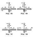
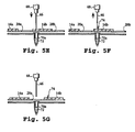
- Shifting means 48 is then signaled to shift the transfer tip away from its raised position and through opening 28b to contact a reagent 72 held in base 50 (Figure 5B). Shifting means 48 then withdraws the tip, along with a portion of such reagent, through the opening to a position above the transport pathway ( Figure 5C). The control unit then signals the conveyor motor to advance belt 22 until a selected region or site of substrate 14b intersects the transfer head's axis A, at which point the belt is again stopped ( Figure 5D). Next, shifting means 48 is signaled to shift the transfer tip away from its raised position toward the selected region of substrate 14b, to transfer a selected amount of reagent, e.g.
- the spotting tip can again be shifted, one or more times, to transfer additional reagent to the substrate.
- additional reagent can be placed at the already-laid spots, or, upon incrementally advancing the substrate under the spotting tip, at previously unspotted regions of the substrate.
- the just-spotted substrate can then be transported downstream ( Figure 5G) for additional spotting at one or more downstream spotting heads, as desired; and the next selected, upstream substrate can be advanced for spotting.
- the just-described operation contemplates an indexed mode of operation, wherein the belt stops and starts repeatedly. It should be appreciated, however, that a continuous mode could be employed instead. If used in the continuous mode, the control unit controls the speed of the conveyor motor, and thus the speed at which substrates are moved along the transport pathway. The control unit also monitors the positions of the various substrates, and signals shifting of the various transfer tips in a fashion permitting reagent retrieval and deposition -- without pausing the movement of the belt/substrates.
- a device like 44 can be provided at each of the spaced locations along the transport pathway having a reagent reservoir.
- Each substrate by this arrangement, can be spotted at one or more of the spaced locations, as desired, during its movement along the transport pathway.
- a plurality of spotting operations such as described above with regard to substrate 14a, can be carried out substantially simultaneously.
- a spotting head at each of the five reagent-supply locations shown in Figure 1, for example, a reagent spot can be placed on each of five tandemly-arranged substrates at substantially the same time.
- the illustrated arrangement can be extended to any desired number of spotting heads.
- One exemplary embodiment contemplates the use of 1,000 spotting heads disposed sequentially at spaced locations along the transport pathway, at various pre-selected laterally offset positions. By this arrangement, 1,000 spots can be laid per second, or so, with one such spot being placed on each of 1,000 substrates along the transport pathway.
- four spotting heads are disposed laterally or obliquely across the transport pathway (along with respective reagent reservoirs thereunder) at each of 250 spaced locations -- again, in a selected laterally offset pattern.
- the various spotting heads at each of the spaced locations can be operated individually, or in mass.
- each transfer tip is independent of all other transfer tips and can therefor be adjusted to accommodate a wide range of spot spacing.
- each transfer device also allows for the service/replacement of each transfer device on an individual basis.
- each individual transfer tip can be attached to and detached from the head, without affecting or otherwise disturbing any other transfer tip(s) of the apparatus.
- Conventional transfer schemes that utilize permanently fixed arrays of transfer devices are inherently deficient if one member of the array malfunctions. In such conventional assemblies, if one of the devices should require service, repair, or replacement, then the entire array of transfer devices must be disassembled and/or replaced. Moreover, in the latter case, any reagents that cannot be retrieved from such conventional devices must also be discarded and replaced.
- the shifting motion (stroke) of each transfer tip is kept to a minimum throughout the transfer operation. That is, at its raised position, the transfer tip clears the uppermost region of a substrate by only a small distance, e.g., less than about 2 mm, and preferably less than about 1 mm. Similarly, at its lowered position, the transfer tip only enters the reagent tube to the extent necessary to pick up a desired amount of reagent. Regarding the latter, reagent levels in each tube can be monitored ( e.g. , optically detected) or calculated so that the control unit can avoid overextending the various transfer tips. This limited motion saves time and, particularly for liquid reagents, avoids concentration variability associated with evaporation.
- any suitable cooling fluid e.g., a gas, or water
- a gas e.g., a gas, or water
- the reagent reservoirs are removed from the apertures along the base, and the transfer tips are then shifted to their lowered positions -- with the reagent-contacting portion of each tip passed through a respective aperture to a location inside the base's channel.
- a suitable cleaning solvent is then flowed through the channel, thereby cleaning the various transfer tips in a substantially simultaneous fashion.
- a dry, warm gas can be flowed through the channel to dry the transfer tips.
- the tubes, or other reagent reservoirs, that are supported in the base for supplying the transfer tips with reagents are also the same containers in which the reagents are stored.
- a storage location e.g ., a file cabinet
- an operator or robot can retrieve one or more vessels containing selected reagents from a storage location (e.g ., a file cabinet), then open each vessel and place it at a respective supply location along the base.
- a storage location e.g ., a file cabinet
- the vessel can simply be resealed and returned to its storage location.
- each reagent remains in its own vessel throughout storage and use.
- reagents that are deposited onto a substrate are preferably transferred from a storage tube, or other reservoir, directly onto the surface of a substrate without the use intermediate containers or lines. After use, the reagent tube is simply resealed prior to storage. It should be appreciated that intermediate containers typically waste fluid because of residues and films that are unavoidably left behind. For applications requiring expensive reagents, intermediate containers can waste an unacceptable amount of fluid.
- an automated shuttle means e.g. , including robots, conveyors, etc.
- the shuttle means can be used to return reagents to their storage locations after use. For example, while one set of reagents is in use, the next set of selected reagents can be retrieved by the shuttle and brought to respective locations along the transport pathway adjacent their points of use.
- the shuttle means can remove the just-used set, place the new set in the base, and return the used set to storage. These steps can be repeated (cycled), preferably under the direction of a programmed computing device, as many times as desired.
- the substrate surface is relatively hydrophilic, i.e., wettable.
- the surface can have native, bound or covalently attached charged groups.
- One such surface is a glass surface having an absorbed layer of a polycationic polymer, such as poly-I-lysine.
- aqueous or predominantly aqueous reagent solution or biological sample is spotted onto a slide having a hydrophilic surface.
- the substrate surface has or is formed to have a relatively hydrophobic character, i.e ., one that causes aqueous medium deposited on the surface to bead.
- a relatively hydrophobic character i.e ., one that causes aqueous medium deposited on the surface to bead.
- hydrophobic polymers such as polystyrene, polypropylene, or polyethylene have desired hydrophobic properties, as do a variety of lubricant or other hydrophobic films that may be applied to the substrate surface.
- a plurality of conveyors can be arranged to pass off substrates from one conveyor to the next.
- two or more conveyors are arranged end-to-end, with the various conveyors collectively forming a transport pathway of greater length than any one of them.
- a non-linear conveyor can be utilized, e.g., a carousel-type arrangement, instead of a linear arrangement as depicted in the drawings.
- the transport pathway can change direction one or more times during or between spotting operations, e.g., two steps forward, two steps back, four steps forward, two steps back, etc. Therefore, while this invention has been described in connection with particular embodiments and examples thereof, the true scope of the invention should not be so limited. Various changes and modification may be made without departing from the scope of the invention, as defined by the appended claims.
Landscapes
- Health & Medical Sciences (AREA)
- Chemical & Material Sciences (AREA)
- Clinical Laboratory Science (AREA)
- Chemical Kinetics & Catalysis (AREA)
- General Health & Medical Sciences (AREA)
- Biochemistry (AREA)
- Physics & Mathematics (AREA)
- General Physics & Mathematics (AREA)
- Immunology (AREA)
- Pathology (AREA)
- Analytical Chemistry (AREA)
- Life Sciences & Earth Sciences (AREA)
- Automatic Analysis And Handling Materials Therefor (AREA)
- Apparatus Associated With Microorganisms And Enzymes (AREA)
- Measuring Or Testing Involving Enzymes Or Micro-Organisms (AREA)
Claims (31)
- Vorrichtung zum Auftragen eines Reagenz auf ein oder mehrere Substrate, umfassend in operativem Zustand:dadurch gekennzeichnet, daßeine Basis, die dazu geeignet ist, um ein solches Reagenz aufzunehmen;ein Fördermittel, das eine Oberfläche aufweist, die eine Vielzahl von Substratetragenden Regionen umfaßt, wobei jede der Substrat-tragenden Regionen dazu geeignet ist, um solch ein Substrat zu tragen;einen Transferkopf, der eine Auftragspitze aufweist, wobei die Spitze für eine Bewegung entlang einer Achse in Richtung und zurück aus einer erhöhten Position montiert ist, bei der die Spitze oberhalb der Fördermitteloberfläche angeordnet ist;einen Antrieb, der operativ mit der Spitze verbunden ist, um dieselbe entlang der Achse zu bewegen; und mindestens eine Kontrolleinheit, die operativ mit dem Fördermittel und dem Antrieb verbunden ist, operativ, für ein oder mehrere ausgewählte Substrate auf der Förderoberfläche,
die Substrat-tragenden Regionen durch dazwischen liegende Zwischenöffnungen voneinander getrennt sind und das Fördermittel dazu operabel ist, um solch ein Substrat entlang eines Transportweges über das Basisteil fortzubewegen; und
die Kontrolleinheit dazu operativ ist, um (i) die Spitze weg aus ihrer erhöhten Position durch eine ausgewählte Öffnung in der Fördermitteloberfläche zu verschieben, um mit Reagenz in der Basis in Kontakt zu kommen, (ii) die Spitze aus dem Reagenz und durch die Öffnung herauszuziehen, durch Verschieben der Spitze in Richtung ihrer erhöhten Position, und (iii) die Spitze weg aus ihrer erhöhten Position in Richtung eines ausgewählten Substrats stromaufwärts der ausgewählten Öffnung zu verschieben, um eine ausgewählte Menge von Reagenz von der Spitze auf eine ausgewählte Region des ausgewählten Substrats zu transferieren. - Vorrichtung nach Anspruch 1, wobei das Fördermittel mit einer Oberfläche zur Verfügung gestellt wird, die eine Vielzahl von voneinander beabstandeten, tandem-angeordneten Substrat-tragenden Regionen aufweist und wobei die Öffnungen zwischen jedem angrenzenden Paar von Substrat-tragenden Regionen definiert sind.
- Vorrichtung nach Anspruch 1 oder 2, wobei der Transferkopf oberhalb der Basis und dem Fördermittel angeordnet ist und wobei die Spitze für eine Bewegung zwischen (i) einer erhöhten Position oberhalb des Fördermittels, (ii) einer Reagenz-abgebenden Position zur Auftragung von Reagenz auf ein durch eine der Substrat-tragenden Regionen getragenes Substrat und (iii) einer ausgestreckten Position unterhalb des Fördermittels, die durch Passieren der Spitze durch eine der Öffnungen erhalten wird, montiert ist.
- Vorrichtung nach Anspruch 1 bis 3, wobei die mindestens eine Kontrolleinheit operativ mit dem Antrieb und dem Fördermittel verbunden ist und dazu effektiv ist, um (i) die Spitze aus ihrer erhöhten Position zu ihrer ausgestreckten Position zu verschieben, durch Durchqueren einer ausgewählten Öffnung in dem Fördermittel, um Reagenz von einem durch die Basis getragenen Reservoir zu entnehmen, (ii) die Spitze nach Schritt (i) auf eine Position oberhalb des Fördermittels anzuheben, (iii) das Fördermittel so zu bewegen, daß ein ausgewähltes Substrat unterhalb der erhobenen Spitze positioniert wird, (iv) die Spitze zu einer Reagenz abgebenden Position zu bewegen, so daß das Reagenz auf einer ausgewählten Region des ausgewählten Substrats aufgetragen wird, (v) nach der Reagenzauftragung, die Spitze zu ihrer erhöhten Position anzuheben, (vi) das Fördermittel so zu bewegen, daß die Spitze oberhalb einer anderen Öffnung positioniert wird und (vii) Schritte (i) bis (vi) für eine gewählte Zahl von Zeiten zu wiederholen.
- Vorrichtung nach einem der voranstehenden Ansprüche, die weiterhin einen oder mehrere zusätzliche Transferköpfe und damit verbundene Antriebsmittel einschließt, die in beabstandeten Positionen entlang des Transportweges angebracht sind, und eine Struktur in der Basis, die dazu geeignet, um ein oder mehrere Reagenzien an jeder der beabstandeten Positionen aufzunehmen.
- Vorrichtung nach einem der voranstehenden Ansprüche, wobei mindestens einer der Transferköpfe von den anderen Transferköpfen lateral versetzt ist.
- Vorrichtung nach einem der voranstehenden Ansprüche, wobei eine Vielzahl von Transferköpfen in einer Reihe angebracht sind, die sich lateral oder quer über die Fördermitteloberfläche bei einer oder mehrerer der beabstandeten Positionen entlang des Transportweges erstreckt.
- Vorrichtung nach einem der voranstehenden Ansprüche, weiterhin umfassend einen Kanal, der sich durch mindestens einen Teil der Basis erstreckt.
- Vorrichtung nach Anspruch 8, weiterhin umfassend eine Flußleitung, die einen Auslaß aufweist, der so angebracht ist, um eine ausgewählte Flüssigkeit in den Kanal hineinzuleiten.
- Vorrichtung nach Anspruch 8 oder 9, wobei die Basis dazu angepaßt ist, um ein oder mehrere Reagenzreservoirs aufzuweisen, so daß sich eine untere Region von jedem Reservoir zumindest teilweise in den Kanal hinein erstreckt.
- Vorrichtung nach Ansprüchen 8 bis 10, wobei die Spitze, wenn weg von ihrer erhöhten Position, mit unverstellter Achse bewegt, mindestens teilweise in den Kanal eintreten kann.
- Vorrichtung nach einem der voranstehenden Ansprüche, wobei die Spitze eine Nadel ist, die ein distales Ende von weniger als ungefähr 500 µm im Durchmesser aufweist.
- Vorrichtung nach einem der voranstehenden Ansprüche, wobei die Spitze einen Kanal von kapillarer Größe einschließt, der dazu angepaßt ist, um Reagenz durch kapillare Aktion einzuziehen, wenn damit in Kontakt verschoben.
- Vorrichtung nach einem der voranstehenden Ansprüche, wobei die Spitze eine Mikropipette ist.
- Vorrichtung nach einem der voranstehenden Ansprüche, wobei der Transferkopf eine Vielzahl von Auftragungsspitzen einschließt, die Seite-an-Seite in beabstandeter Relation montiert sind; wobei jede Spitze für eine Bewegung entlang einer jeweiligen Achse hin und zurück aus einer erhöhten Position, bei der die Spitze oberhalb der Fördermitteloberfläche angebracht ist, geeignet ist.
- Vorrichtung nach einem der voranstehenden Ansprüche, wobei ein lang gezogenes Netz die Fördermitteloberfläche definiert, wobei jedes der Substrat-tragenden Teile ein für das Auftragen geeignetes Substrat definiert.
- Vorrichtung nach Anspruch 16, wobei das lang gezogene Netz ein flexibles Membranmaterial ist.
- Vorrichtung nach einem der voranstehenden Ansprüche, wobei ein lang gezogener flexibler Gurt die Fördermitteloberfläche definiert.
- Vorrichtung zum Auftragen eines Reagenz auf ein oder mehrere Substrate, umfassend in operativem Zustand:dadurch gekennzeichnet, daßeine Basis, die dazu angepaßt ist, um ein solches Reagenz aufzunehmen;ein Fördermittel, das eine Oberfläche aufweist, die eine Vielzahl von Substratregionen definiert;einen Transferkopf, der eine Auftragsspitze aufweist, wobei die Spitze für eine Bewegung entlang einer Achse in Richtung und weg aus einer erhöhten Position, bei der die Spitze oberhalb der Fördermitteloberfläche angeordnet ist, montiert ist;einen Antrieb, der operativ mit der Spitze verbunden ist, zur Bewegung derselben entlang der Achse;
die Substratregionen voneinander durch dazwischen liegende Zwischenöffnungen voneinander getrennt sind und das Fördermittel operabel ist, um solch ein Substrat entlang eines Transportwegs über die Basis zu bewegen; und
eine Kontrolleinheit, die operativ mit dem Fördermittel und dem Antrieb verbunden ist, operativ für eine oder mehrere ausgewählte Substratregionen, die durch die Fördermittel-oberfläche definiert sind, um (i) die Spitze weg aus ihrer erhöhten Position durch eine ausgewählte Öffnung in der Fördermitteloberfläche zu verschieben, um mit Reagenz in der Basis in Kontakt zu kommen, (ii) die Spitze aus dem Reagenz und durch die Öffnung durch Verschieben der Spitze in Richtung ihrer erhöhten Position herauszuziehen und (iii) die Spitze weg aus ihrer erhöhten Position in Richtung einer ausgewählten Substratregion stromaufwärts von der ausgewählten Öffnung zu verschieben, um eine ausgewählte Menge von Reagenz von der Spitze auf eine ausgewählte Stelle der ausgewählten Substratregion zu transferieren. - Vorrichtung nach Anspruch 19, wobei das Fördermittel mit einer Oberfläche zur Verfügung gestellt wird, die eine Vielzahl von beabstandeten, in tandem-angeordneten Substratregionen aufweist und wobei die Öffnungen zwischen jedem angrenzenden Paar von Substratregionen definiert sind.
- Vorrichtung nach Anspruch 19 oder Anspruch 20, wobei die Fördermitteloberfläche ein flexibles Netzmaterial ist.
- Verfahren zum Auftragen einer Reagenz auf ein oder mehrere Substrate, umfassend die Schritte von:(i) Fortbewegen einer Vielzahl von voneinander beabstandeten, in tandem-angeordneten Substraten entlang eines Transportwegs, der sich über einen Reagenz-Zuführort hinweg erstreckt;(ii) aus einer Position über dem Reagenz-Zuführort und dem Weg(a) Ausstrecken eines Reagenz-Transferinstruments durch eine dazwischenliegende Region, die ein angrenzendes Paar von sich fortbewegenden Substraten trennt, um in Kontakt mit an dem Reagenz-Zuführort gehaltenem Reagenz in Kontakt zu kommen;(b) Herausziehen des Reagenz-Transferinstruments, zusammen mit einem Teil von solchem Reagenz, durch die dazwischenliegende Region zu einer Position oberhalb des Transportwegs, und(c) Transferieren einer ausgewählten Menge von Reagenz von dem Reagenz-Transferinstrument auf eine ausgewählte Region eines ausgewählten Substrats stromaufwärts von der dazwischenliegenden Region.
- Verfahren nach Anspruch 22, wobei die Substrate integral als voneinander beabstandete expansive Teile ausgebildet sind, die entlang eines lang gezogenen Netzmaterials zur Verfügung gestellt werden, und jede der dazwischenliegenden Regionen eine Öffnung ist, die durch das Netzmaterial zwischen den angrenzenden Substratteilen geformt ist.
- Verfahren nach einem der Ansprüche 22 oder 23, wobei die Substrate unter der Verwendung eines Fördermittels fortbewegt werden, das einen beweglichen Gurt aufweist, der eine Vielzahl von in tandem-angeordneten Substrat-tragenden Regionen aufweist; wobei jedes Substrat an einem definierten Ort auf einer der entsprechenden Substrat-tragenden Regionen plaziert wird.
- Verfahren nach einem der Ansprüche 22 bis 24, wobei der Transportweg sich über eine Vielzahl von Reagenz-Zuführorten erstreckt, die an beabstandeten Positionen entlang des Wegs angeordnet sind; und wobei Schritt (ii) an zwei oder mehreren der voneinander beabstandeten Positionen auf eine Art durchgeführt wird, die dazu effektiv ist, um eine Vielzahl von Reagenzauftragungen auf dem ausgewählten Substrat herzustellen.
- Verfahren nach einem der Ansprüche 22 bis 25, wobei mindestens einer der Reagenzauftragungen auf dem ausgewählten Substrat von den anderen Reagenzauftragungen lateral versetzt ist.
- Verfahren nach einem der Ansprüche 22 bis 26, wobei Schritt (ii) mindestens zweimal auf eine im wesentlichen parallele Weise unter der Verwendung von getrennten Reagenz-Transferinstrumenten an einer oder mehrerer der beabstandeten Positionen durchgeführt wird.
- Verfahren nach einem der Ansprüche 22 bis 27, weiter umfassend die Schritte von:Entfernen jedes Reagenz/jeder Reagenzien, die an dem Reagenz-Zuführort gehalten werden;Ausstrecken von mindestens einem Teil des Reagenz-Transferinstruments in den Reagenz-Zuführort;Spülen einer Reinigungslösung entlang des Reagenz-Zuführorts, so daß sie mit dem Reagenz-Transferinstrument in Kontakt kommt und dieses reinigt.
- Verfahren nach einem der Ansprüche 22 bis 28, weiterhin umfassend den Schritt von:mit mindestens einem Teil des Reagenz-Transferinstruments in den Reagenz-Zuführort hinein erstreckt, Spülen eines Gases entlang des Reagenz-Zuführorts, so daß dieses mit dem gereinigten Reagenz-Transferinstrument in Kontakt kommt und dieses trocknet.
- Verfahren nach einem der Ansprüche 22 bis 29, weiterhin umfassend die Schritte von:Plazieren eines Behälters, an dem Reagenz-Zuführort der ein ausgewähltes flüssiges Reagenz enthält;
undSpülen einer Kühlflüssigkeit entlang des Reagenz-Zuführorts, so daß sie mit dem Behälter in Kontakt kommt, wodurch der Verdampfungsverlust des ausgewählten flüssigen Reagenz verringert wird. - Verfahren nach einem der Ansprüche 22 bis 30, weiterhin umfassend die Schritte von:vor Schritt (i) Entnehmen eines Gefäßes, das ein ausgewähltes Reagenz enthält, von einem Lagerort und Plazieren des Gefäßes bei dem Reagenz-Zuführort; undanschließend an Schritt (ii), Entnehmen des Gefäßes von dem Reagenz-Zuführort und Zurückbringen des Gefäßes zu seinem Lagerort.
Applications Claiming Priority (3)
| Application Number | Priority Date | Filing Date | Title |
|---|---|---|---|
| US09/293,659 US6245297B1 (en) | 1999-04-16 | 1999-04-16 | Apparatus and method for transferring small volumes of substances |
| US293659 | 1999-04-16 | ||
| PCT/US2000/009670 WO2000063705A1 (en) | 1999-04-16 | 2000-04-11 | Apparatus and method for transferring small volumes of substances |
Publications (2)
| Publication Number | Publication Date |
|---|---|
| EP1159622A1 EP1159622A1 (de) | 2001-12-05 |
| EP1159622B1 true EP1159622B1 (de) | 2002-10-02 |
Family
ID=23129993
Family Applications (1)
| Application Number | Title | Priority Date | Filing Date |
|---|---|---|---|
| EP00922064A Expired - Lifetime EP1159622B1 (de) | 1999-04-16 | 2000-04-11 | Vorrichtung und verfahren zur übertragung von kleinen substanzvolumen |
Country Status (8)
| Country | Link |
|---|---|
| US (3) | US6245297B1 (de) |
| EP (1) | EP1159622B1 (de) |
| JP (1) | JP3659890B2 (de) |
| AT (1) | ATE225516T1 (de) |
| AU (1) | AU751309B2 (de) |
| CA (1) | CA2368660C (de) |
| DE (1) | DE60000539T2 (de) |
| WO (1) | WO2000063705A1 (de) |
Families Citing this family (82)
| Publication number | Priority date | Publication date | Assignee | Title |
|---|---|---|---|---|
| US7285422B1 (en) | 1997-01-23 | 2007-10-23 | Sequenom, Inc. | Systems and methods for preparing and analyzing low volume analyte array elements |
| US7112449B1 (en) * | 2000-04-05 | 2006-09-26 | Nanogram Corporation | Combinatorial chemical synthesis |
| US20020001544A1 (en) * | 1997-08-28 | 2002-01-03 | Robert Hess | System and method for high throughput processing of droplets |
| US6132685A (en) * | 1998-08-10 | 2000-10-17 | Caliper Technologies Corporation | High throughput microfluidic systems and methods |
| US6511849B1 (en) * | 1999-04-23 | 2003-01-28 | The Sir Mortimer B. Davis - Jewish General Hospital | Microarrays of biological materials |
| US6245297B1 (en) * | 1999-04-16 | 2001-06-12 | Pe Corporation (Ny) | Apparatus and method for transferring small volumes of substances |
| US8298485B2 (en) * | 1999-07-08 | 2012-10-30 | Lee H. Angros | In situ heat induced antigen recovery and staining apparatus and method |
| US7951612B2 (en) * | 1999-07-08 | 2011-05-31 | Lee H. Angros | In situ heat induced antigen recovery and staining apparatus and method |
| US6979425B1 (en) * | 1999-10-04 | 2005-12-27 | Robodesign International, Inc. | High capacity microarray dispensing |
| US6656432B1 (en) | 1999-10-22 | 2003-12-02 | Ngk Insulators, Ltd. | Micropipette and dividedly injectable apparatus |
| GB2356253B (en) * | 1999-11-09 | 2003-11-05 | Bruker Daltonik Gmbh | Contamination-free transfer of biological specimens |
| EP1246698B1 (de) * | 2000-01-06 | 2006-09-20 | Caliper Life Sciences, Inc. | Vorrichtungen und verfahren für hochdurchsatz-probenentnahme und analyse |
| JP3750460B2 (ja) * | 2000-02-18 | 2006-03-01 | 日立工機株式会社 | 分注装置及び分注方法 |
| US6447723B1 (en) * | 2000-03-13 | 2002-09-10 | Packard Instrument Company, Inc. | Microarray spotting instruments incorporating sensors and methods of using sensors for improving performance of microarray spotting instruments |
| US6878554B1 (en) | 2000-03-20 | 2005-04-12 | Perkinelmer Las, Inc. | Method and apparatus for automatic pin detection in microarray spotting instruments |
| US7521245B1 (en) | 2000-06-05 | 2009-04-21 | Perkinelmer Las, Inc. | Method for washing and drying pins in microarray spotting instruments |
| JP2002005942A (ja) * | 2000-06-23 | 2002-01-09 | Teruaki Ito | 検体処理ユニット及び検体処理システム |
| US6902702B1 (en) * | 2000-08-16 | 2005-06-07 | University Health Network | Devices and methods for producing microarrays of biological samples |
| EP1245278A3 (de) * | 2000-09-15 | 2003-12-10 | Agfa-Gevaert | Bahnförmiges Material mit Mikroöffnungen für Anwendungen in der kombinatorischen Chemie |
| US6353774B1 (en) * | 2000-09-22 | 2002-03-05 | Virtek Engineering Sciences Inc. | High precision vision guided positioning device |
| AU2002245047A1 (en) | 2000-10-30 | 2002-07-24 | Sequenom, Inc. | Method and apparatus for delivery of submicroliter volumes onto a substrate |
| US20030170148A1 (en) * | 2001-01-31 | 2003-09-11 | Mcentee John F. | Reaction chamber roll pump |
| US7112305B2 (en) * | 2001-01-31 | 2006-09-26 | Agilent Technologies, Inc. | Automation-optimized microarray package |
| US6855925B2 (en) | 2001-02-14 | 2005-02-15 | Picoliter Inc. | Methods, devices, and systems using acoustic ejection for depositing fluid droplets on a sample surface for analysis |
| DE60217303T2 (de) * | 2001-02-28 | 2007-08-30 | Iogen Energy Corp., Nepean | Methode zur behandlung von lignin- und zellulosehaltigen beschickungen zur erhöhten produktion von xylose und ethanol |
| US8414774B2 (en) | 2001-04-25 | 2013-04-09 | Agilent Technologies, Inc. | Systems and methods for high-throughput screening of fluidic samples |
| US7588725B2 (en) | 2001-04-25 | 2009-09-15 | Biotrove, Inc. | High throughput autosampler |
| WO2009059286A1 (en) | 2007-11-02 | 2009-05-07 | Biotrove, Inc. | Devices and methods for coupling mass spectrometry devices with chromatography systems |
| US6812030B2 (en) | 2001-04-25 | 2004-11-02 | Biotrove, Inc. | System and method for high throughput sample preparation and analysis using column chromatography |
| JP2004532983A (ja) * | 2001-05-03 | 2004-10-28 | アフィメトリックス インコーポレイテッド | 高スループットマイクロアレイスポッティングシステムおよび方法 |
| US7041257B2 (en) * | 2001-09-25 | 2006-05-09 | Cytonome, Inc. | Microfabricated two-pin liquid sample dispensing system |
| US6579724B2 (en) * | 2001-09-13 | 2003-06-17 | First Ten Angstroms | Dispensing method and apparatus for dispensing very small quantities of fluid |
| US7153699B2 (en) * | 2001-12-21 | 2006-12-26 | Cytonome, Inc. | Microfabricated two-pin system for biomolecule crystallization |
| US20070054408A1 (en) * | 2001-09-25 | 2007-03-08 | Cytonome, Inc. | Microfabricated two-pin system for biomolecule crystallization |
| US6936474B2 (en) | 2001-11-05 | 2005-08-30 | Industrial Technology Research Institute | Method and apparatus for manufacturing biochip |
| US7258839B2 (en) * | 2001-12-21 | 2007-08-21 | Cytonome, Inc. | Temperature controlled microfabricated two-pin liquid sample dispensing system |
| US7232547B2 (en) * | 2002-03-22 | 2007-06-19 | Marshfield Clinic | Apparatus and method for testing and continuously reading low-volume samples |
| ES2594333T3 (es) * | 2002-05-17 | 2016-12-19 | Becton, Dickinson And Company | Sistema automatizado para aislar, amplificar y detectar una secuencia blanco de ácidos nucleicos |
| US20030231986A1 (en) * | 2002-06-18 | 2003-12-18 | Eastman Kodak Company | Micro-array identification means |
| DE20210451U1 (de) * | 2002-07-05 | 2002-10-17 | Leica Microsystems Nussloch GmbH, 69226 Nußloch | Antrieb für eine Vorrichtung zum Einfärben von Objekten |
| DE10233212B4 (de) * | 2002-07-22 | 2006-07-06 | Siemens Ag | Messvorrichtung mit einer Biochip-Anordnung und Verwendung der Vorrichtung für ein Hochdurchsatzanalyseverfahren |
| US7810380B2 (en) | 2003-03-25 | 2010-10-12 | Tearlab Research, Inc. | Systems and methods for collecting tear film and measuring tear film osmolarity |
| EP1546386A4 (de) * | 2002-09-17 | 2006-05-10 | Pharmacia Corp | Erhaltung von rna und reverser transkriptase während der automatisierten handhabung von flüssigkeiten |
| ITBO20020607A1 (it) * | 2002-09-26 | 2004-03-27 | Cryorobotics | Sistema automatico per la conservazione a temperatura |
| US6881588B2 (en) * | 2002-10-18 | 2005-04-19 | Indiana University Research & Technology Corporation | Fluid treatment device |
| US6911182B2 (en) * | 2002-10-18 | 2005-06-28 | Indiana University Research And Technology Corporation | Device for placement of effluent |
| JP3765788B2 (ja) * | 2002-11-29 | 2006-04-12 | 照明 伊藤 | 検体分注システム |
| US7125727B2 (en) * | 2003-01-29 | 2006-10-24 | Protedyne Corporation | Sample handling tool with piezoelectric actuator |
| US7097070B2 (en) * | 2003-08-15 | 2006-08-29 | Protedyne Corporation | Method and apparatus for handling small volume fluid samples |
| DE10347311A1 (de) * | 2003-10-08 | 2005-05-12 | Ehrfeld Mikrotechnik Ag | Verfahren und Vorrichtung zur Durchführung von Reaktionen |
| US7585463B2 (en) * | 2003-10-24 | 2009-09-08 | Aushon Biosystems, Inc. | Apparatus and method for dispensing fluid, semi-solid and solid samples |
| US7396512B2 (en) | 2003-11-04 | 2008-07-08 | Drummond Scientific Company | Automatic precision non-contact open-loop fluid dispensing |
| US20050201895A1 (en) * | 2004-03-12 | 2005-09-15 | Eric Donsky | Systems and methods for delivering a sample fluid to a receiving substrate |
| DE102004029909A1 (de) * | 2004-06-21 | 2006-01-19 | Roche Diagnostics Gmbh | Verfahren und Vorrichtung zur Herstellung von bindungsfähigen Reagenzträgern |
| TWI276915B (en) * | 2004-06-30 | 2007-03-21 | Innolux Display Corp | Photo-resist stripping process and equipment |
| TW200632314A (en) * | 2004-12-07 | 2006-09-16 | Honeywell Analytics Ag | Gas detection method and system |
| US20080166786A1 (en) * | 2005-03-10 | 2008-07-10 | Shusaku Nishiyama | Pump Unit, Syringe Unit, Method for Delivering Particles, and Method for Delivering Cells |
| US20080269076A1 (en) * | 2005-05-06 | 2008-10-30 | Applera Corporation | Multiple Capillary Device and Method for Synthesis and Dispensing |
| MX2007014655A (es) | 2005-05-24 | 2008-04-02 | Lee H Angros | Aparato y metodo para la recuperacion y coloracion de antigenos in situ inducida por calor. |
| ATE528652T1 (de) * | 2005-06-29 | 2011-10-15 | Hoffmann La Roche | Analysesystem mit testband |
| US20080003667A1 (en) * | 2006-05-19 | 2008-01-03 | Affymetrix, Inc. | Consumable elements for use with fluid processing and detection systems |
| US7855077B2 (en) * | 2006-09-29 | 2010-12-21 | Beckman Coulter, Inc. | Method and device for test sample loading |
| JP5461389B2 (ja) * | 2007-05-02 | 2014-04-02 | シーメンス・ヘルスケア・ダイアグノスティックス・インコーポレーテッド | 試薬表面への診断液のピエゾ計量分配 |
| JP5296054B2 (ja) * | 2007-05-02 | 2013-09-25 | シーメンス・ヘルスケア・ダイアグノスティックス・インコーポレーテッド | 診断用液体のマイクロ流体装置内への圧電ディスペンシング |
| US20090180931A1 (en) | 2007-09-17 | 2009-07-16 | Sequenom, Inc. | Integrated robotic sample transfer device |
| US7940188B2 (en) | 2008-02-07 | 2011-05-10 | Veltek Associates, Inc. | Air sampling system having a plurality of air sampling devices with their own flow switches |
| WO2010025425A1 (en) | 2008-08-29 | 2010-03-04 | Angros Lee H | Multiplexed microscope slide staining apparatus |
| US8588966B2 (en) | 2009-01-09 | 2013-11-19 | Automed Technologies, Inc. | Cabinet system |
| US8103379B2 (en) | 2009-01-09 | 2012-01-24 | Automed Technologies, Inc. | Medication cabinetry |
| US20100248981A1 (en) * | 2009-03-27 | 2010-09-30 | Affymetrix, Inc. | System and methods for processing microarrays |
| US8956309B2 (en) * | 2010-01-19 | 2015-02-17 | Becton, Dickinson And Company | Sensor strip positioning mechanism |
| EP2537148B1 (de) * | 2010-02-18 | 2021-06-23 | Veltek Associates, INC. | Verbessertes luftprobenahmesystem |
| US9533278B2 (en) | 2014-08-08 | 2017-01-03 | Applied Materials, Inc. | Patterned deposition of liquid films for biomedical devices |
| US9939416B2 (en) | 2014-08-28 | 2018-04-10 | Veltek Assoicates, Inc. | Programmable logic controller-based system and user interface for air sampling in controlled environments |
| EP3198257B1 (de) | 2014-09-23 | 2020-08-12 | Tearlab Research, Inc. | System zur integration einer mikrofluidischen tränenprobenahme und lateral-flow-analyse von interessierenden analyten |
| EP3314269A4 (de) | 2015-06-26 | 2019-01-23 | Abbott Laboratories | Reaktionsgefässtauschervorrichtung für einen diagnostischen analysator |
| US20200041532A1 (en) * | 2017-07-18 | 2020-02-06 | Hewlett-Packard Development Company, L.P. | Reagent dispensing systems |
| WO2019017918A1 (en) * | 2017-07-18 | 2019-01-24 | Hewlett-Packard Development Company, L.P. | REAGENT DISTRIBUTION DEVICES |
| US11366125B2 (en) * | 2017-07-18 | 2022-06-21 | Hewlett-Packard Development Company, L.P. | Substrate conveyance systems |
| US11154161B2 (en) * | 2017-12-05 | 2021-10-26 | Robert Almblad | Automated food cooking system |
| CN111512138B (zh) * | 2017-12-28 | 2024-08-09 | 利拉伐控股有限公司 | 配量模块 |
| US11344153B2 (en) | 2018-03-04 | 2022-05-31 | Robert Almblad | Vertical cooking system |
Family Cites Families (40)
| Publication number | Priority date | Publication date | Assignee | Title |
|---|---|---|---|---|
| US3164304A (en) | 1961-05-08 | 1965-01-05 | Standard Thomson Corp | Liquid dispensing apparatus for small quantities |
| US3329964A (en) | 1965-06-24 | 1967-07-04 | Xerox Corp | Facsimile recording apparatus |
| US3334354A (en) | 1966-03-17 | 1967-08-01 | Xerox Corp | Dotting ink recorder |
| US3850775A (en) | 1973-03-09 | 1974-11-26 | Polaroid Corp | Laminating apparatus |
| US3945448A (en) | 1974-07-18 | 1976-03-23 | Frito-Lay, Inc. | System for package weight control |
| US4057145A (en) * | 1976-03-19 | 1977-11-08 | Wray Betty B | Compliance dispenser for oral medication |
| US4351799A (en) | 1981-07-15 | 1982-09-28 | Gross Valery N | Micrometering liquid sample dispenser |
| US4542808A (en) | 1983-06-30 | 1985-09-24 | House Of Lloyd, Inc. | Order filling system |
| US4681742A (en) | 1984-10-01 | 1987-07-21 | Cetus Corporation | Assay tray |
| US4952518A (en) | 1984-10-01 | 1990-08-28 | Cetus Corporation | Automated assay machine and assay tray |
| US4828102A (en) | 1988-02-01 | 1989-05-09 | Custom Technologies, Inc. | Cargo conveyor system |
| GB8809611D0 (en) | 1988-04-22 | 1988-05-25 | Darougar S | Deposition apparatus |
| US5204268A (en) * | 1988-06-02 | 1993-04-20 | Fuji Photo Film Co., Ltd. | Method and apparatus for applying liquid samples |
| US4893513A (en) | 1988-11-01 | 1990-01-16 | Nordson Corporation | Method and apparatus for bond testing |
| US5320734A (en) | 1989-12-05 | 1994-06-14 | Daikin Industries, Ltd. | Test apparatus for measuring concentration of test substance in liquid |
| US5595707A (en) | 1990-03-02 | 1997-01-21 | Ventana Medical Systems, Inc. | Automated biological reaction apparatus |
| ATE154981T1 (de) | 1990-04-06 | 1997-07-15 | Perkin Elmer Corp | Automatisiertes labor für molekularbiologie |
| US5425918A (en) * | 1990-07-18 | 1995-06-20 | Australian Biomedical Corporation | Apparatus for automatic tissue staining for immunohistochemistry |
| US5192506A (en) | 1991-02-14 | 1993-03-09 | P B Diagnostic Systems, Inc. | Incubator port closure for automated assay system |
| US5389408A (en) | 1992-03-18 | 1995-02-14 | Printron, Inc. | Method for curing metal particles into continuous conductors |
| GB2274017B (en) * | 1992-06-16 | 1995-08-30 | Samsung Electronics Co Ltd | A backward compatible HDTV recording/reproducing system |
| NL9201147A (nl) | 1992-06-26 | 1994-01-17 | Gerber Jan | Doseerapparaat alsmede doseerwerkwijze. |
| US5508200A (en) | 1992-10-19 | 1996-04-16 | Tiffany; Thomas | Method and apparatus for conducting multiple chemical assays |
| US5525515A (en) | 1993-02-03 | 1996-06-11 | Blattner; Frederick R. | Process of handling liquids in an automated liquid handling apparatus |
| RU2041263C1 (ru) * | 1993-08-11 | 1995-08-09 | Геннадий Моисеевич Ершов | Способ микродозирования водных растворов веществ на носитель и устройство для его осуществления |
| US5807522A (en) | 1994-06-17 | 1998-09-15 | The Board Of Trustees Of The Leland Stanford Junior University | Methods for fabricating microarrays of biological samples |
| US5601980A (en) | 1994-09-23 | 1997-02-11 | Hewlett-Packard Company | Manufacturing method and apparatus for biological probe arrays using vision-assisted micropipetting |
| JP3571092B2 (ja) * | 1994-12-20 | 2004-09-29 | 富士写真フイルム株式会社 | 乾式分析フィルム片への試料液点着方法 |
| US5551487A (en) | 1995-03-10 | 1996-09-03 | Hewlett-Packard Company | Micro-dispenser for preparing assay plates |
| US5811306A (en) * | 1995-09-04 | 1998-09-22 | Fuji Photo Film Co., Ltd. | Liquid spotting method |
| US5587522A (en) | 1995-12-26 | 1996-12-24 | Selby; Theodore W. | Multiple-part and/or supported gas-containing vessel to establish desired heat flux |
| US5733509A (en) | 1996-04-17 | 1998-03-31 | Motorola, Inc. | Method and system for synthesizing oligonucleotides using nucleotide-specific dispensing bars |
| US5958342A (en) | 1996-05-17 | 1999-09-28 | Incyte Pharmaceuticals, Inc. | Jet droplet device |
| DE19628178C1 (de) | 1996-07-12 | 1997-09-18 | Bruker Franzen Analytik Gmbh | Verfahren zum Beladen von Probenträgern für Massenspektrometer |
| US5746116A (en) | 1997-04-28 | 1998-05-05 | Apw/Wyott Foodservice Equipment Company | Rapid toasting apparatus |
| JP4199342B2 (ja) * | 1997-12-02 | 2008-12-17 | エフ.ホフマン−ラ ロシュ アーゲー | 自動サンプル処理装置、および自動サンプル処理装置におけるサンプル識別方法 |
| US6251686B1 (en) * | 1998-02-26 | 2001-06-26 | Edward J. Studer | Liquid transfer apparatus |
| US6245297B1 (en) * | 1999-04-16 | 2001-06-12 | Pe Corporation (Ny) | Apparatus and method for transferring small volumes of substances |
| JP3390377B2 (ja) * | 1999-10-05 | 2003-03-24 | 株式会社日立製作所 | 反応装置 |
| GB2356253B (en) * | 1999-11-09 | 2003-11-05 | Bruker Daltonik Gmbh | Contamination-free transfer of biological specimens |
-
1999
- 1999-04-16 US US09/293,659 patent/US6245297B1/en not_active Expired - Lifetime
-
2000
- 2000-04-11 AT AT00922064T patent/ATE225516T1/de not_active IP Right Cessation
- 2000-04-11 JP JP2000612759A patent/JP3659890B2/ja not_active Expired - Fee Related
- 2000-04-11 WO PCT/US2000/009670 patent/WO2000063705A1/en not_active Ceased
- 2000-04-11 DE DE60000539T patent/DE60000539T2/de not_active Expired - Lifetime
- 2000-04-11 CA CA002368660A patent/CA2368660C/en not_active Expired - Fee Related
- 2000-04-11 AU AU42307/00A patent/AU751309B2/en not_active Ceased
- 2000-04-11 EP EP00922064A patent/EP1159622B1/de not_active Expired - Lifetime
-
2001
- 2001-04-30 US US09/846,467 patent/US6355487B2/en not_active Expired - Lifetime
- 2001-12-12 US US10/016,979 patent/US6916447B2/en not_active Expired - Lifetime
Also Published As
| Publication number | Publication date |
|---|---|
| US6355487B2 (en) | 2002-03-12 |
| AU751309B2 (en) | 2002-08-15 |
| JP2002542490A (ja) | 2002-12-10 |
| DE60000539D1 (de) | 2002-11-07 |
| US6916447B2 (en) | 2005-07-12 |
| CA2368660A1 (en) | 2000-10-26 |
| US20010018216A1 (en) | 2001-08-30 |
| WO2000063705A1 (en) | 2000-10-26 |
| US6245297B1 (en) | 2001-06-12 |
| US20020041829A1 (en) | 2002-04-11 |
| DE60000539T2 (de) | 2003-03-06 |
| EP1159622A1 (de) | 2001-12-05 |
| CA2368660C (en) | 2005-09-06 |
| ATE225516T1 (de) | 2002-10-15 |
| JP3659890B2 (ja) | 2005-06-15 |
| AU4230700A (en) | 2000-11-02 |
Similar Documents
| Publication | Publication Date | Title |
|---|---|---|
| EP1159622B1 (de) | Vorrichtung und verfahren zur übertragung von kleinen substanzvolumen | |
| US7211148B2 (en) | Apparatus and method for spotting a substrate | |
| EP1675682B1 (de) | Vorrichtung und verfahren zur dosierung von flüssigen, halbfesten und festen proben | |
| US20020064482A1 (en) | Method and apparatus for developing DNA microarrays | |
| EP1181100A1 (de) | Integriertes probenbearbeitungssystem | |
| US6936474B2 (en) | Method and apparatus for manufacturing biochip |
Legal Events
| Date | Code | Title | Description |
|---|---|---|---|
| PUAI | Public reference made under article 153(3) epc to a published international application that has entered the european phase |
Free format text: ORIGINAL CODE: 0009012 |
|
| 17P | Request for examination filed |
Effective date: 20010921 |
|
| AK | Designated contracting states |
Kind code of ref document: A1 Designated state(s): AT BE CH CY DE DK ES FI FR GB GR IE IT LI LU MC NL PT SE |
|
| AX | Request for extension of the european patent |
Free format text: AL;LT;LV;MK;RO;SI |
|
| 17Q | First examination report despatched |
Effective date: 20011121 |
|
| GRAG | Despatch of communication of intention to grant |
Free format text: ORIGINAL CODE: EPIDOS AGRA |
|
| GRAG | Despatch of communication of intention to grant |
Free format text: ORIGINAL CODE: EPIDOS AGRA |
|
| GRAH | Despatch of communication of intention to grant a patent |
Free format text: ORIGINAL CODE: EPIDOS IGRA |
|
| GRAH | Despatch of communication of intention to grant a patent |
Free format text: ORIGINAL CODE: EPIDOS IGRA |
|
| GRAA | (expected) grant |
Free format text: ORIGINAL CODE: 0009210 |
|
| AK | Designated contracting states |
Kind code of ref document: B1 Designated state(s): AT BE CH CY DE DK ES FI FR GB GR IE IT LI LU MC NL PT SE |
|
| PG25 | Lapsed in a contracting state [announced via postgrant information from national office to epo] |
Ref country code: BE Free format text: LAPSE BECAUSE OF FAILURE TO SUBMIT A TRANSLATION OF THE DESCRIPTION OR TO PAY THE FEE WITHIN THE PRESCRIBED TIME-LIMIT Effective date: 20021002 Ref country code: AT Free format text: LAPSE BECAUSE OF FAILURE TO SUBMIT A TRANSLATION OF THE DESCRIPTION OR TO PAY THE FEE WITHIN THE PRESCRIBED TIME-LIMIT Effective date: 20021002 Ref country code: GR Free format text: LAPSE BECAUSE OF FAILURE TO SUBMIT A TRANSLATION OF THE DESCRIPTION OR TO PAY THE FEE WITHIN THE PRESCRIBED TIME-LIMIT Effective date: 20021002 Ref country code: FI Free format text: LAPSE BECAUSE OF FAILURE TO SUBMIT A TRANSLATION OF THE DESCRIPTION OR TO PAY THE FEE WITHIN THE PRESCRIBED TIME-LIMIT Effective date: 20021002 |
|
| REF | Corresponds to: |
Ref document number: 225516 Country of ref document: AT Date of ref document: 20021015 Kind code of ref document: T |
|
| REG | Reference to a national code |
Ref country code: GB Ref legal event code: FG4D |
|
| REG | Reference to a national code |
Ref country code: CH Ref legal event code: EP |
|
| REG | Reference to a national code |
Ref country code: IE Ref legal event code: FG4D |
|
| REF | Corresponds to: |
Ref document number: 60000539 Country of ref document: DE Date of ref document: 20021107 |
|
| PG25 | Lapsed in a contracting state [announced via postgrant information from national office to epo] |
Ref country code: DK Free format text: LAPSE BECAUSE OF FAILURE TO SUBMIT A TRANSLATION OF THE DESCRIPTION OR TO PAY THE FEE WITHIN THE PRESCRIBED TIME-LIMIT Effective date: 20030102 Ref country code: PT Free format text: LAPSE BECAUSE OF FAILURE TO SUBMIT A TRANSLATION OF THE DESCRIPTION OR TO PAY THE FEE WITHIN THE PRESCRIBED TIME-LIMIT Effective date: 20030102 |
|
| RAP2 | Party data changed (patent owner data changed or rights of a patent transferred) |
Owner name: PE CORPORATION (NY) |
|
| REG | Reference to a national code |
Ref country code: CH Ref legal event code: NV Representative=s name: ISLER & PEDRAZZINI AG |
|
| RAP2 | Party data changed (patent owner data changed or rights of a patent transferred) |
Owner name: APPLERA CORPORATION |
|
| LTIE | Lt: invalidation of european patent or patent extension |
Effective date: 20021002 |
|
| NLT2 | Nl: modifications (of names), taken from the european patent patent bulletin |
Owner name: PE CORPORATION (NY) |
|
| ET | Fr: translation filed | ||
| PG25 | Lapsed in a contracting state [announced via postgrant information from national office to epo] |
Ref country code: CY Free format text: LAPSE BECAUSE OF FAILURE TO SUBMIT A TRANSLATION OF THE DESCRIPTION OR TO PAY THE FEE WITHIN THE PRESCRIBED TIME-LIMIT Effective date: 20030411 Ref country code: LU Free format text: LAPSE BECAUSE OF NON-PAYMENT OF DUE FEES Effective date: 20030411 Ref country code: IE Free format text: LAPSE BECAUSE OF NON-PAYMENT OF DUE FEES Effective date: 20030411 |
|
| PG25 | Lapsed in a contracting state [announced via postgrant information from national office to epo] |
Ref country code: ES Free format text: LAPSE BECAUSE OF FAILURE TO SUBMIT A TRANSLATION OF THE DESCRIPTION OR TO PAY THE FEE WITHIN THE PRESCRIBED TIME-LIMIT Effective date: 20030429 |
|
| PG25 | Lapsed in a contracting state [announced via postgrant information from national office to epo] |
Ref country code: MC Free format text: LAPSE BECAUSE OF NON-PAYMENT OF DUE FEES Effective date: 20030430 |
|
| NLT2 | Nl: modifications (of names), taken from the european patent patent bulletin |
Owner name: APPLERA CORPORATION |
|
| NLXE | Nl: other communications concerning ep-patents (part 3 heading xe) |
Free format text: PAT. BUL. 03/2003 PAGE 372: CORR.: PE CORPORATION. |
|
| PLBE | No opposition filed within time limit |
Free format text: ORIGINAL CODE: 0009261 |
|
| STAA | Information on the status of an ep patent application or granted ep patent |
Free format text: STATUS: NO OPPOSITION FILED WITHIN TIME LIMIT |
|
| 26N | No opposition filed |
Effective date: 20030703 |
|
| NLS | Nl: assignments of ep-patents |
Owner name: APPLERA CORPORATION |
|
| REG | Reference to a national code |
Ref country code: IE Ref legal event code: MM4A |
|
| REG | Reference to a national code |
Ref country code: CH Ref legal event code: PUE Owner name: APPLERA CORPORATION Free format text: PE CORPORATION (NY)#850 LINCOLN CENTRE DRIVE#FOSTER DRIVE, CA 94404-1128 (US) -TRANSFER TO- APPLERA CORPORATION#850 LINCOLN CENTRE DRIVE#FOSTER CITY, CA 94404 (US) |
|
| REG | Reference to a national code |
Ref country code: FR Ref legal event code: TP |
|
| REG | Reference to a national code |
Ref country code: FR Ref legal event code: TP |
|
| PGFP | Annual fee paid to national office [announced via postgrant information from national office to epo] |
Ref country code: NL Payment date: 20050316 Year of fee payment: 6 |
|
| PGFP | Annual fee paid to national office [announced via postgrant information from national office to epo] |
Ref country code: FR Payment date: 20050418 Year of fee payment: 6 |
|
| PGFP | Annual fee paid to national office [announced via postgrant information from national office to epo] |
Ref country code: SE Payment date: 20050420 Year of fee payment: 6 |
|
| PGFP | Annual fee paid to national office [announced via postgrant information from national office to epo] |
Ref country code: CH Payment date: 20050421 Year of fee payment: 6 |
|
| PG25 | Lapsed in a contracting state [announced via postgrant information from national office to epo] |
Ref country code: SE Free format text: LAPSE BECAUSE OF NON-PAYMENT OF DUE FEES Effective date: 20060412 |
|
| PG25 | Lapsed in a contracting state [announced via postgrant information from national office to epo] |
Ref country code: CH Free format text: LAPSE BECAUSE OF NON-PAYMENT OF DUE FEES Effective date: 20060430 Ref country code: LI Free format text: LAPSE BECAUSE OF NON-PAYMENT OF DUE FEES Effective date: 20060430 |
|
| PG25 | Lapsed in a contracting state [announced via postgrant information from national office to epo] |
Ref country code: NL Free format text: LAPSE BECAUSE OF NON-PAYMENT OF DUE FEES Effective date: 20061101 |
|
| REG | Reference to a national code |
Ref country code: CH Ref legal event code: PL |
|
| EUG | Se: european patent has lapsed | ||
| NLV4 | Nl: lapsed or anulled due to non-payment of the annual fee |
Effective date: 20061101 |
|
| REG | Reference to a national code |
Ref country code: FR Ref legal event code: ST Effective date: 20061230 |
|
| PGFP | Annual fee paid to national office [announced via postgrant information from national office to epo] |
Ref country code: IT Payment date: 20070518 Year of fee payment: 8 |
|
| PG25 | Lapsed in a contracting state [announced via postgrant information from national office to epo] |
Ref country code: FR Free format text: LAPSE BECAUSE OF NON-PAYMENT OF DUE FEES Effective date: 20060502 |
|
| REG | Reference to a national code |
Ref country code: GB Ref legal event code: 732E Free format text: REGISTERED BETWEEN 20090514 AND 20090520 |
|
| PG25 | Lapsed in a contracting state [announced via postgrant information from national office to epo] |
Ref country code: IT Free format text: LAPSE BECAUSE OF NON-PAYMENT OF DUE FEES Effective date: 20080411 |
|
| REG | Reference to a national code |
Ref country code: GB Ref legal event code: 732E Free format text: REGISTERED BETWEEN 20100121 AND 20100127 |
|
| PGFP | Annual fee paid to national office [announced via postgrant information from national office to epo] |
Ref country code: DE Payment date: 20160405 Year of fee payment: 17 Ref country code: GB Payment date: 20160406 Year of fee payment: 17 |
|
| REG | Reference to a national code |
Ref country code: DE Ref legal event code: R119 Ref document number: 60000539 Country of ref document: DE |
|
| GBPC | Gb: european patent ceased through non-payment of renewal fee |
Effective date: 20170411 |
|
| PG25 | Lapsed in a contracting state [announced via postgrant information from national office to epo] |
Ref country code: DE Free format text: LAPSE BECAUSE OF NON-PAYMENT OF DUE FEES Effective date: 20171103 |
|
| PG25 | Lapsed in a contracting state [announced via postgrant information from national office to epo] |
Ref country code: GB Free format text: LAPSE BECAUSE OF NON-PAYMENT OF DUE FEES Effective date: 20170411 |