EP1158769A1 - Appareil d'analyse avec un mode de préimpression - Google Patents
Appareil d'analyse avec un mode de préimpression Download PDFInfo
- Publication number
- EP1158769A1 EP1158769A1 EP01110175A EP01110175A EP1158769A1 EP 1158769 A1 EP1158769 A1 EP 1158769A1 EP 01110175 A EP01110175 A EP 01110175A EP 01110175 A EP01110175 A EP 01110175A EP 1158769 A1 EP1158769 A1 EP 1158769A1
- Authority
- EP
- European Patent Office
- Prior art keywords
- image data
- digital
- data
- digital image
- image
- Prior art date
- Legal status (The legal status is an assumption and is not a legal conclusion. Google has not performed a legal analysis and makes no representation as to the accuracy of the status listed.)
- Withdrawn
Links
Images


Classifications
-
- H—ELECTRICITY
- H04—ELECTRIC COMMUNICATION TECHNIQUE
- H04N—PICTORIAL COMMUNICATION, e.g. TELEVISION
- H04N1/00—Scanning, transmission or reproduction of documents or the like, e.g. facsimile transmission; Details thereof
- H04N1/40—Picture signal circuits
- H04N1/40068—Modification of image resolution, i.e. determining the values of picture elements at new relative positions
Definitions
- the present invention relates to scanning devices according to the preamble of Claim 6 and a method for manipulating images.
- the original When scanning documents, the original is scanned and as a digital image in one Main computer, a so-called host and / or a workstation stored. If the scanned image is not suitable for printing or other types of publication, the scanner parameters are adjusted and the image is re-scanned and processed. If the image was captured with the highest resolution, it can be varied Further processing in the host can be used. Implementation of the changes and their Processing takes on due to the high amount of image processing required the host and / or the workstation often takes a long time. The image adjustment for Compensation of scanner parameters is therefore time-consuming and labor-intensive.
- Finite impulse response filters are for a specific image aperture constructed. By changing the scanning speed, this aperture is in Scanning direction changed. The filters can be used to adapt to different ones Apertures can be changed, but support a non-symmetrical FIR filter is neither an easy task nor an inexpensive solution.
- the object of the present invention is to provide a scanning device and a method for To scale an image that does not have the disadvantages mentioned above and in which the raw image data is stored in a data buffer and the Operator has the possibility in a prepress mode the raw data before Check and manipulate printing or other reproduction of the image.
- Another object of the present invention is to provide a scanning device using a Scaling without changing the speed of the scanner motor.
- a scanning device which is operated by an operator and in which printed material is converted into electronic data by a User equipment used includes a converter that converts light into digital Converts raw image data, an image processor, which the digital raw image data receives and manipulates and provides manipulated image data, an output data path, via which the data is forwarded to the user device, a Buffer for storing data and a control device which checks whether the digital image data is stored in the buffer by which Image processor can be manipulated, forwarded via the output data path or manipulated by the image processor and then stored in the buffer become.
- the present invention provides a useful prepress mode for one Scanner, because not all scanned image data are acceptable to a viewer straight away are. It is therefore an advantage if the operator has the opportunity to register display the scanned image, edit it and display it again without that an additional scan is necessary.
- FIG. 1 is a digital copy / print reproduction system 10 shown, which is a (marking or) Printing device 12, an original document reading device, in particular one Scanning device 14 and a computer or a workstation 16 with a Operator interface, e.g. B. a monitor 18 and a keyboard 20 comprises.
- the Marking device 12, the computer / workstation 16, the monitor 18 and the keyboard 20 together or in each case form a user device 30 which is used by the scanning device 14 receives digital image data output via a data output line 15 and it reproduced in any way.
- a digital printer is a printing device 12 that receives digital image data and the images defined by the data on a medium (e.g. B. paper).
- a typical application of a scanner 14 is reading Original documents 24, their digital reproduction for verification by an operator, who decides which data is finally sent to a printing device for reproducing the Images can be shared on paper.
- the operation of the scanner 14 is similar to that of a conventional copier, as an original document 24 is first exposed by a lamp.
- the light is from the light and dark areas of the original are proportional to the brightness of the Originals reflect.
- the light is directed through mirrors and onto the Directed photodetector elements.
- the image is created by the photodetector elements resolved sequentially into small dots (so-called picture elements or pixels) and the light for converted every point into a proportional electrical signal.
- They are different Types of photoelectric converters are known, e.g. B. photodiodes, phototransistors and Charge-coupled devices (CCDs) (on these
- the tones of the original are fashioned into a pattern of proportional, sequential Voltage values resolved.
- the sequential electrical signal sent by the CCD corresponds in analog form to the image density recorded for each pixel.
- the electrical Signal is then converted from an A / D converter to an equivalent digital signal converted.
- an output of only one bit (a signal line) to indicate the entire tonal range.
- gray values are also reproduced.
- the (analog) Input signal accordingly if the density of the original changes from white to gray changed black.
- a two-bit output enables a division of this color range in four gray values for conversion into a digital signal.
- the picture can by means of electronic circuits in an image processor by signal processing to be changed.
- the scanning device 14 generates a series of electrical signals, which reproduce the image content of the original document 24.
- a user device e.g. Legs Printer unit 12 or other operator interface, e.g. B.
- a computer / a Workstation 16 communicates where the image is displayed.
- the scanning device 14 further includes an automatic document feeder 32, the consecutively one after the other original templates in paper form Scanner mechanism with platen 38 feeds where the originals automatically the read head, e.g. B. a linear arrangement of solid-state CCDs can be read.
- the originals automatically the read head e.g. B. a linear arrangement of solid-state CCDs can be read.
- documents in book or sheet form can also be placed on the Scanner mechanism be placed with platen 38.
- FIG. 2 shows the functional blocks of a scanner 14 according to the invention, which an automatic document feeder 32, an exposure subsystem 34 optical subsystem 36, a scanner mechanism with platen 38, a Motion control and corresponding sensors 40, scanner interface software 42, Scanner control software 44, logic and control device 46, communication interface hardware 48, CCD and analog front-end electronics 50, a digital one Image processing processor 52, a first buffer 54 for raw image data (so-called. raw image data or RID) and a second buffer 56 for manipulated Image data (so-called manipulated image data or MID).
- the digital image processor 52 and the Buffer 54, 56 form an image processing or [P block 60.
- Die automatic document feeder 32, exposure subsystem 34, the optical subsystem 36, the scanner mechanism with platen 38 and the CCDs and the analog front-end electronics 50 supply digital image data in "raw form", ie. H. raw form, to a buffer 54.
- "raw form" ie. H. raw form
- the original was read in and digitized, but the image data was only slight or not at all edited or manipulated to change the properties of the image.
- only system or hardware errors usually occur Corrected image areas, d. H. z.
- the raw image data stored in the raw image data buffer can be for many different purposes are used, as explained in more detail below.
- the raw image data can e.g. B. directly for viewing or printing on Operator block 30 are directed. This gives the operator the opportunity to review the scanned image and decide whether to continue editing the image is necessary or the data should be changed in the digital image processor. In this It is advantageous if the data in the clipboard is as long as possible to stay saved, the period of the available storage capacity is dependent.
- the raw image data can also be sent to the IP block for manipulation.
- the IP block receives the raw image data (from a camera card interface via the Buffer) for editing and storage in an external memory (or a local memory) located on a PCI bus.
- the one in external storage stored image data can then be forwarded to the host or in digital Image processor can be used for further processing.
- the processing consists of several functions for manipulating the raw image data, e.g. B. pixel correction, Skew correction, screen display, FIR filtering, scaling, Compression, color simulation by random scattering, so-called error diffusion or error diffusion, automatic brightness and color value adjustment etc.
- the manipulated data of the image processor are then in a second Intermediate memory 56 for manipulated image data (MID) is stored.
- MID manipulated image data
- exemplary here two separate image buffers 54, 56 are shown, both buffers 54, 56 can be provided on the same memory chip or on the same card. If the Data from the MID buffer 56 are required, they are stored on the Data interface 48 called.
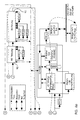
- FIGS. 3a-d an embodiment of the present invention is shown which is a CCD 70, which passes analog image information to an A / D converter 72.
- For Clarification are process, image and data paths that one of the detail views 3b to 3d lead to another detailed view 3b to 3d marked with letters. The corresponding path continues on the same letter in which it is in the previous figure ends. The same applies to FIGS. 4b to 4e.
- the digital raw image data are transmitted via a clock and a linearity correction block passed to a raw image buffer 54. Then the data extracted and one machining operation or several machining operations in which the data is manipulated before being in a MID Buffer 56 are stored.
- the image editing operations include e.g. B. (but not only) skew corrections, screen display, FIR filtering, Scaling, compression, error diffusion and automatic brightness and color value Adaptation .
- the linearity correction eliminates irregularities in the output of the CCDs constant input balanced.
- pixel correction individual pixel data corrected that deviate from an expected pixel value.
- the skew correction compensates for misalignment of the original documents during scanning occured.
- Screen display, error diffusion and threshold Segmentation method, (so-called thresholding) is the number of data per pixel (from eight Bits per pixel reduced to two bits per pixel).
- FIR filtering is a low-pass filter technique for edge sharpening.
- scaling the image is enlarged or downsized. Compression refers to a typical data compression technique to reduce the amount of memory required to save the image.
- the Error diffusion algorithm is an adaptive method based on the following observation based: The decision was made in a simple binary threshold procedure hit a particular pixel to print, so the error is caused by that decision emerges in the picture, known. If e.g. B. A template is 75% black and a black one Bit is printed, so 25% of a bit is too much black on the print. The error value is distributed to neighboring, randomly selected points. So if too much black was printed, the error is counted towards the surrounding points, so that these contain a little more white. If, on the other hand, too little black was printed, the Error value subtracted from the surrounding points so that these are slightly more black contain. No grid is used for this procedure.
- 4a-e show the sequence of the data flow through the image processor: After the Data formatting 80, gain correction 82, zero offset correction are carried out 84, automatic brightness and color value adjustment 86, Skew correction 88, FIR filtering 90, scaling 92 and a block 94 which Thresholding, screening and error diffusion (as a reproduction method) contains.
- An example of the data manipulation carried out in the IP block is scaling.
- the purpose of scaling is to enlarge a digital image into one Range between 100% and 400% (in 1% steps) or the reduction of the image in a range between 100% and 25% (in 1% increments).
- the scanned images in the scan direction and transverse to the scan direction or enlarged downsized, with the enlargement or reduction in the scan direction and the Enlargement or reduction across the scan direction take place independently of each other, so there is a possibility to enlarge the image in one direction and it zoom out in the other direction at the same time.
- the image reproduction to 100% as well Reductions (in both directions) can be done at full productivity.
- an algorithm decides pixel by pixel whether the pixel in the final image appears (with interpolation) or is omitted. With a 100% Playback is preserved every pixel.
- additional pixels are added used the image to enlarge it.
- the picture to be enlarged is first displayed in the Storage stored, then called up and enlarged.
- the system runs when enlarging at the same clock speed, but has to process a larger amount of data.
- the engine speed of the scanner 14 cannot be changed because the scaling is mathematical, in particular is performed algorithmically by storing the stored raw data in "scaled" Image data (i.e., data stored in the reproducing device / marking device 12 display scaled image to be used).
- An algorithm that can be used for scaling works with a bilinear interpolation method, in which the value of the current pixel and the value of three neighboring pixels are used to determine the pixel value to be stored. Since the position of the desired output pixel can lie between two pixels, a method for interpolating the pixel value from the neighboring pixels is required.
- the bilinear interpolation method has interpolation precision bits and pixel address bits. Two-dimensional scaling can easily be achieved through the use of address registers which define the pixel position of the pixel to be processed for the output scaled image.
- the registers have an integer part and a fractional part, the latter containing a user definable number of precision and interpolation bits.
- Independent X and Y scaling requires the calculation of two delta variables namely one in the scanning direction and one transverse to the scanning direction. For each axis two separate address counters must be provided.
- Bits 9 and 10 determine the interpolation factors involved in the interpolation Pixels can be used. It is both an arithmetic register in the scan direction and a Computing registers are provided transversely to the scanning direction, which work in parallel, so that the final interpolation factor based on the results of both computational registers. Bit 11 can be viewed as an extension or roll-over bit. If this bit is 1 the address counter goes to the next pixel. In Fig. 6 it is shown how a value is determined for a "new pixel". A given pixel A is of a 4x4 matrix of the possible interpolation positions. These 16 positions are calculated using the two bits from the arithmetic register across the scan direction (bits 9 and 10) and the Computing register addressed in scan direction (bits 9 and 10).
- Another scaling method provides that the image lines are stored in a FIFO memory and then called up one after the other in order to decide whether the data should be retained or not.
- a pixel value (800H) for each input pixel is added to the arithmetic register and the result is compared with the magnification value to decide whether there is a rollover case. If the arithmetic register value is equal to or larger than the magnification value, there is a rollover case and the pixel is retained.
- bits 9 and 10 are no longer automatically the interpolation bits. If bits 0 to 11 in the accumulator are zero, the interpolation is "00". If bits 0 to 8 in the accumulator are zero, the following table is used: Bits 10 and 9 Interpolation results 00 00 01 11 10 10 11 01
- the same table can be used for a reduction or enlargement or a combination in order to determine the correct factors for A, B, C, D for determining the new pixel value.
- the calculation is: ((A_Factor x A) + (B_Faktor x B) + (C_Faktor x C) + (D_Faktor x D)) / 16
- Fig. 6 the bilinear interpolation calculation is shown when two interpolation bits be used.
- the integer part of the X and Y address registers has periods and Pixel A towards each other.
- the desired output pixel is in the range of pixels A, B, C and D.
- the fractional part of the X address register contains both Interpolation bits 11.
- the fractional part of the Y address register contains in both Interpolation bits 10.
- the position of the desired output pixel is relative to the four pixels that border it. It should be noted here that it is a 4x4 grid is involved - with three interpolation bits an 8x8 grid would result.
- the Equation to calculate the new pixel has the following coefficients: 2/16 for A, 6/16 for B, 2/16 for C and 6/16 for D. The closer a pixel of the desired the more weighted it is.
- the address registers are used to determine the x and y coordinates of the position of the desired pixels used.
- the following examples illustrate
- a second process is launched Gear set in which the multibit image from the raw image data buffer read out and processed in the image processor 52, e.g. B. on the desired by the operator Dimension is enlarged.
- An advantage of this method is that the FIR filter is not on asymmetrical apertures must be adjusted since the picture in the normal Operating speed was scanned.
- the electronic hardware generates data in the Standard bandwidth, but reads the data at a lower speed than the data coming in from an image. Because the scaling process is in the same mode takes place like the rest of the prepress processes, is a fine adjustment of the Scaling window and the other scaling parameters possible without that Original must be re-scanned.
- the scanner operation according to the invention with the Prepress mode setting in scanner 14 begins.
- This mode allows the image or image data to be viewed at different stages, i.e. H. from the raw image data generated in the scanning device 14 to the “finished” version of the Image after the manipulation of the data in the context of one or more Image editing operations.
- One or more original documents 24 are inserted and scanned.
- the raw image data is stored in the raw image data buffer 54 saved. If necessary, the raw image data is sent to the operator interface 18 or the printer 12 passed. Otherwise it takes place in one Image processing operation or in several image processing operations Data manipulation of the raw image data. After the image processing, the manipulated Image data is stored in a manipulated data buffer 56.
- the manipulated data On request the manipulated data will be sent to the viewer to view or create a printout Operator interface 18 passed.
- the raw image data remain in the raw image data buffer for so long 54 until they are no longer used. That way a scanned image of an original document 24 is repeatedly edited, checked or be scanned until it reaches the desired one, suitable for high-volume printing Has reached state.
- This scanner mode is called "prepress mode", because it allows the image to be processed before the actual printing process.
Applications Claiming Priority (2)
| Application Number | Priority Date | Filing Date | Title |
|---|---|---|---|
| US20494300P | 2000-05-17 | 2000-05-17 | |
| US204943P | 2000-05-17 |
Publications (1)
| Publication Number | Publication Date |
|---|---|
| EP1158769A1 true EP1158769A1 (fr) | 2001-11-28 |
Family
ID=22760114
Family Applications (1)
| Application Number | Title | Priority Date | Filing Date |
|---|---|---|---|
| EP01110175A Withdrawn EP1158769A1 (fr) | 2000-05-17 | 2001-05-07 | Appareil d'analyse avec un mode de préimpression |
Country Status (2)
| Country | Link |
|---|---|
| EP (1) | EP1158769A1 (fr) |
| DE (1) | DE10122102A1 (fr) |
Citations (6)
| Publication number | Priority date | Publication date | Assignee | Title |
|---|---|---|---|---|
| EP0009378A1 (fr) * | 1978-09-14 | 1980-04-02 | Xerox Corporation | Appareil de transcription d'image |
| GB2117902A (en) * | 1982-04-06 | 1983-10-19 | Loge Interpretation Syst | Colour detection and-or modification |
| US4468755A (en) * | 1980-10-31 | 1984-08-28 | Tokyo Shibaura Denki Kabushiki Kaisha | Document size conversion circuit for a document filing system |
| US4533942A (en) * | 1982-05-28 | 1985-08-06 | Dr. -Ing. Rudolf Hell Gmbh | Method and apparatus for reproducing an image which has a coarser resolution than utilized in scanning of the image |
| EP0246010A1 (fr) * | 1986-05-12 | 1987-11-19 | Crosfield Electronics Limited | Afficheur d'image |
| US4833625A (en) * | 1986-07-09 | 1989-05-23 | University Of Arizona | Image viewing station for picture archiving and communications systems (PACS) |
-
2001
- 2001-05-07 EP EP01110175A patent/EP1158769A1/fr not_active Withdrawn
- 2001-05-07 DE DE2001122102 patent/DE10122102A1/de not_active Withdrawn
Patent Citations (6)
| Publication number | Priority date | Publication date | Assignee | Title |
|---|---|---|---|---|
| EP0009378A1 (fr) * | 1978-09-14 | 1980-04-02 | Xerox Corporation | Appareil de transcription d'image |
| US4468755A (en) * | 1980-10-31 | 1984-08-28 | Tokyo Shibaura Denki Kabushiki Kaisha | Document size conversion circuit for a document filing system |
| GB2117902A (en) * | 1982-04-06 | 1983-10-19 | Loge Interpretation Syst | Colour detection and-or modification |
| US4533942A (en) * | 1982-05-28 | 1985-08-06 | Dr. -Ing. Rudolf Hell Gmbh | Method and apparatus for reproducing an image which has a coarser resolution than utilized in scanning of the image |
| EP0246010A1 (fr) * | 1986-05-12 | 1987-11-19 | Crosfield Electronics Limited | Afficheur d'image |
| US4833625A (en) * | 1986-07-09 | 1989-05-23 | University Of Arizona | Image viewing station for picture archiving and communications systems (PACS) |
Also Published As
| Publication number | Publication date |
|---|---|
| DE10122102A1 (de) | 2001-11-22 |
Similar Documents
| Publication | Publication Date | Title |
|---|---|---|
| DE3645046C2 (fr) | ||
| US6469801B1 (en) | Scanner with prepress scaling mode | |
| DE19816123B4 (de) | Verfahren zum Erzeugen von Mehrfachwiedergaben eines Bilds mit einer Mehrfachbildabtastvorrichtung | |
| DE3339002C2 (de) | Verfahren und Einrichtung zum Verarbeiten eines Bildsignals | |
| DE2948341A1 (de) | Verfahren zum verarbeiten von bildelementen und vorrichtung zum verarbeiten einer bilddatenreihe | |
| DE60111816T2 (de) | Adaptives Filterverfahren und -vorrichtung zur Entrasterung abgetasteter Halbtonbilddaten | |
| DE3522707A1 (de) | Bildverarbeitungsgeraet | |
| DE3640369C2 (fr) | ||
| DE2654481A1 (de) | Faksimile-bildfernuebertragungsvorrichtung | |
| DE3520405C2 (fr) | ||
| DE69631812T2 (de) | System und Verfahren für ein hochadressierbares Drucksystem | |
| DE3037127A1 (de) | Bilderzeugungsverfahren und -geraet | |
| DE3436631C2 (fr) | ||
| EP0095514A1 (fr) | Procédé et appareil pour la reproduction d'une image avec une définition plus grossière que celle à l'analyse de l'image | |
| DE69738149T2 (de) | Punktzuwachskompensation | |
| EP0132453A1 (fr) | Procédé et appareil pour minimiser des erreurs lors du traitement numérique de signaux électriques | |
| DE69937985T2 (de) | Bildverarbeitungsvorrichtung und -Verfahren | |
| DE3527301A1 (de) | Bildleseeinrichtung | |
| DE3521682A1 (de) | Verfahren zum abtasten und aufzeichnen von bildern | |
| DE19538030A1 (de) | Zugriffstabelle mit höherer Genauigkeit aus einer Zugriffstabelle mit niedrigerer Genauigkeit zur verbesserten Toneinstellung | |
| DE60005761T2 (de) | System und Verfahren zum Stempeln eines elektronisches Bildes mit Information | |
| DE4409389A1 (de) | Bildverarbeitungseinrichtung | |
| DE60027187T2 (de) | System und verfahren zur verarbeitung mehrerer pegel mit pegelbeschraenkung | |
| DE19543488A1 (de) | Verfahren und Vorrichtung zur Bildwert-Korrektur bei optoelektronischen Wandlern | |
| EP1158769A1 (fr) | Appareil d'analyse avec un mode de préimpression |
Legal Events
| Date | Code | Title | Description |
|---|---|---|---|
| PUAI | Public reference made under article 153(3) epc to a published international application that has entered the european phase |
Free format text: ORIGINAL CODE: 0009012 |
|
| 17P | Request for examination filed |
Effective date: 20010827 |
|
| AK | Designated contracting states |
Kind code of ref document: A1 Designated state(s): AT BE CH CY DE DK ES FI FR GB GR IE IT LI LU MC NL PT SE TR |
|
| AX | Request for extension of the european patent |
Free format text: AL;LT;LV;MK;RO;SI |
|
| AKX | Designation fees paid |
Free format text: AT BE CH CY DE DK ES FI FR GB GR IE IT LI LU MC NL PT SE TR |
|
| RAP1 | Party data changed (applicant data changed or rights of an application transferred) |
Owner name: EASTMAN KODAK COMPANY |
|
| STAA | Information on the status of an ep patent application or granted ep patent |
Free format text: STATUS: THE APPLICATION HAS BEEN WITHDRAWN |
|
| 18W | Application withdrawn |
Effective date: 20060316 |