EP1158567A2 - Betriebsvorrichtung für eine quecksilberfreie Hochleistungsentladungslampe und quecksilberfreie Metallhalogenidlampe - Google Patents
Betriebsvorrichtung für eine quecksilberfreie Hochleistungsentladungslampe und quecksilberfreie Metallhalogenidlampe Download PDFInfo
- Publication number
- EP1158567A2 EP1158567A2 EP01113019A EP01113019A EP1158567A2 EP 1158567 A2 EP1158567 A2 EP 1158567A2 EP 01113019 A EP01113019 A EP 01113019A EP 01113019 A EP01113019 A EP 01113019A EP 1158567 A2 EP1158567 A2 EP 1158567A2
- Authority
- EP
- European Patent Office
- Prior art keywords
- mercury
- arc tube
- arc
- electrodes
- metal halide
- Prior art date
- Legal status (The legal status is an assumption and is not a legal conclusion. Google has not performed a legal analysis and makes no representation as to the accuracy of the status listed.)
- Withdrawn
Links
Images


Classifications
-
- H—ELECTRICITY
- H01—ELECTRIC ELEMENTS
- H01J—ELECTRIC DISCHARGE TUBES OR DISCHARGE LAMPS
- H01J61/00—Gas-discharge or vapour-discharge lamps
- H01J61/02—Details
- H01J61/12—Selection of substances for gas fillings; Specified operating pressure or temperature
- H01J61/125—Selection of substances for gas fillings; Specified operating pressure or temperature having an halogenide as principal component
-
- H—ELECTRICITY
- H01—ELECTRIC ELEMENTS
- H01J—ELECTRIC DISCHARGE TUBES OR DISCHARGE LAMPS
- H01J61/00—Gas-discharge or vapour-discharge lamps
- H01J61/02—Details
- H01J61/04—Electrodes; Screens; Shields
- H01J61/10—Shields, screens, or guides for influencing the discharge
- H01J61/106—Shields, screens, or guides for influencing the discharge using magnetic means
-
- H—ELECTRICITY
- H01—ELECTRIC ELEMENTS
- H01J—ELECTRIC DISCHARGE TUBES OR DISCHARGE LAMPS
- H01J61/00—Gas-discharge or vapour-discharge lamps
- H01J61/02—Details
- H01J61/12—Selection of substances for gas fillings; Specified operating pressure or temperature
- H01J61/16—Selection of substances for gas fillings; Specified operating pressure or temperature having helium, argon, neon, krypton, or xenon as the principle constituent
-
- H—ELECTRICITY
- H01—ELECTRIC ELEMENTS
- H01J—ELECTRIC DISCHARGE TUBES OR DISCHARGE LAMPS
- H01J61/00—Gas-discharge or vapour-discharge lamps
- H01J61/82—Lamps with high-pressure unconstricted discharge having a cold pressure > 400 Torr
- H01J61/827—Metal halide arc lamps
-
- H—ELECTRICITY
- H01—ELECTRIC ELEMENTS
- H01J—ELECTRIC DISCHARGE TUBES OR DISCHARGE LAMPS
- H01J61/00—Gas-discharge or vapour-discharge lamps
- H01J61/84—Lamps with discharge constricted by high pressure
-
- H—ELECTRICITY
- H01—ELECTRIC ELEMENTS
- H01J—ELECTRIC DISCHARGE TUBES OR DISCHARGE LAMPS
- H01J61/00—Gas-discharge or vapour-discharge lamps
- H01J61/84—Lamps with discharge constricted by high pressure
- H01J61/86—Lamps with discharge constricted by high pressure with discharge additionally constricted by close spacing of electrodes, e.g. for optical projection
Definitions
- the present invention relates to a mercury-free high-intensity discharge lamp operating apparatus and a mercury-free metal halide lamp that do not contain mercury as the luminous material.
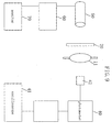
- FIG. 1 shows a cross sectional configuration of a metal halide lamp.
- the metal halide lamp shown in FIG. 1 includes an arc tube (luminous bulb) 1 made of quartz glass and sealing portions 2 that are positioned at both ends of the arc tube 1 and seal the arc tube 1.
- a pair of electrodes 3 made of tungsten are provided in the arc tube 1, and a luminous material 6 including mercury and metal halide, and a rare gas (not shown) are enclosed in the arc tube 1.
- the pair of electrodes 3 in the arc tube 1 are connected to molybdenum foils 4 at one end, and the molybdenum foils 4 are sealed with the sealing portions 2.
- Lead wires 5 are connected to the other ends of the molybdenum foils 4.
- the lead wires 5 are to be electrically connected to a ballast (not shown).
- the principle of light emission of the metal halide lamp shown in FIG. 1 will be described briefly.
- the lamp is turned on by applying a voltage to the lead wires 5 from the ballast, a part of or the entire metal halide 6 evaporates.
- the evaporated metal halide is dissociated to metal atoms and halogen atoms by arc discharge occurring between the pair of electrodes 3, and thus the metal atoms are excited so that light is emitted.
- the dissociated metal atoms are recombined with the halogen atoms, and return to a metal halide. This cycle phenomenon is repeated to allow the lamp to be stably on.
- the metal halide has a lower vapor pressure than that of mercury, the metal halide is readily excited and emitted, so that there is a tendency that emission caused by an added metal mercury is stronger than emission caused by mercury in metal halide lamps. Therefore, mercury primarily serves as a buffering gas to determine a voltage in the arc tube 1. A rare gas in the arc tube 1 serves as a gas for starting the lamp.
- the technique disclosed in Japanese Laid-Open Patent Publication No. 55-86062 includes the step of disposing a strong rare earth magnet above the arc tube 1 in a metal halide lamp containing mercury in the arc tube 1 to lower the arc 7 down by utilizing repulsion (Lorentz force) between the magnet and the arc 7, thereby suppressing the curving of the arc 7.
- Japanese Laid-Open Patent Publication No. 9-161725 uses an electromagnet as means for applying a magnetic field, in place of the rare earth magnet.
- an electromagnetic to change the position of the arc such as Japanese Laid-Open Patent Publication No. 11-312495, 11-317103, and 2000-12251.
- the mercury-free metal halide lamps have significantly different characteristics than those of metal halide lamps containing mercury.
- arc curving can be suppressed by applying a magnetic field to the mercury-metal halide lamp.
- the manner in which a magnetic field is applied and the principle of suppression of curving are very different from those for the metal halide lamp containing mercury.
- the arc 7 itself is unstable and a phenomenon that the arc 7 vibrates was observed. This vibration of the arc 7 is not preferable because it results in a flickering when used as a lamp.
- a mercury-free high-intensity discharge lamp operating apparatus of the present invention includes a horizontally operated high-intensity discharge lamp including an arc tube in which a luminous material is enclosed and a pair of electrodes are arranged in the arc tube; a ballast including an alternating current generation means for supplying alternating current to the pair of electrodes; and a magnetic field application means for applying in substantially vertical direction a magnetic field having a component that is substantially perpendicular to a straight line connecting heads of the pair of electrodes; wherein mercury is not included as the luminous material in the arc tube; and the present invention satisfies the relationship 0 ⁇ (100BW / f) - P 0 d ⁇ 100 wherein B (mT) is the magnetic field applied to a center between the heads of the pair of electrodes, d (mm) is a distance between the heads of the pair of electrodes, P 0 (MPa) is a pressure inside the arc tube during steady-state operation, W (W) is a power
- a mercury-free high-intensity discharge lamp operating apparatus of the present invention includes a horizontally operated high-intensity discharge lamp including an arc tube in which a luminous material is enclosed and a pair of electrodes are arranged in the arc tube; a ballast including an alternating current generation means for supplying alternating current to the pair of electrodes; and a magnetic field application means for applying in substantially vertical direction a magnetic field having a component that is substantially perpendicular to a straight line connecting the heads of said pair of electrodes; wherein mercury is not included as the luminous material in the arc tube, and at least a rare gas is included in the arc tube; and the present invention satisfies the relationship 0 ⁇ (10BW / f) - Pd ⁇ 10 wherein B (mT) is the magnetic field applied to a center between the heads of the pair of electrodes, d (mm) is a distance between the heads of the pair of electrodes, P (MPa) is a pressure of the enclosed rare gas at 20°C
- the pressure P of the enclosed rare gas is in the range of 0.1(MPa) ⁇ P ⁇ 2.5(MPa).
- the operating frequency f during steady-state operation is in the range of 40(Hz) ⁇ f.
- the magnetic field B is in the range of B ⁇ 500(mT).
- the distance d between the heads of the electrodes is in the range of 2 ⁇ d(mm).
- the high-intensity discharge lamp is a metal halide lamp including at least indium halide as the luminous material in the arc tube.
- the present invention further includes a reflecting mirror for reflecting light emitted by the high-intensity discharge lamp; wherein a center of an arc of the mercury-free high-intensity discharge lamp is arranged on an optical axis of the reflecting mirror.
- a mercury-free metal halide lamp of the present invention includes an arc tube in which a luminous material is enclosed and a pair of electrode are arranged in the arc tube; wherein at least an indium halide serving as the luminous material and a rare gas are contained in the arc tube; and mercury is not included as the luminous material in the arc tube; and the present invention satisfies Pd ⁇ 4.6, wherein d (mm) is a distance between the heads of the pair of electrodes, and P (MPa) is a pressure of the enclosed rare gas at room temperature.
- the pressure P of the enclosed rare gas is at least 0.3(MPa) at room temperature.
- the distance d is at least 2(mm).
- the metal halide lamp is operated in a perpendicular direction.
- the metal halide lamp is operated in a horizontal direction; and the present invention further includes a magnetic field application means for applying a magnetic field having a component that is substantially perpendicular to a straight line connecting the heads of the pair of electrodes, thereby suppressing arc curving.
- the metal halide lamp is of an alternating current lighting type where an alternating current is supplied to the pair of electrodes.
- a scandium halide, a sodium halide, and a thallium halide are contained as the luminous material in the arc tube.
- a halogen constituting the halides is at least one selected from the group consisting of iodine and bromine.
- the rare gas is Xe (xenon).
- the mercury-free metal halide lamp further includes a reflecting mirror for reflecting light emitted by the metal halide lamp; wherein a center of an arc of the mercury-free metal halide lamp is arranged on an optical axis of the reflecting mirror.
- the relationship of the equation 0 ⁇ (10BW / f) - P 0 d ⁇ 100 is satisfied, wherein B (mT) is the magnetic field applied to the center between the heads of the pair of electrodes, d (mm) is the distance between the heads of the pair of electrodes, P 0 (MPa) is the pressure inside the arc tube during steady-state operation, W (W) is the power consumed during steady-state operation, and f (Hz) is the steady-state frequency during steady-state operation, or the relationship of the equation 0 ⁇ (10BW / f) - Pd ⁇ 10 is satisfied, where P (MPa) is the pressure of the enclosed rare gas at 20°C.
- the arc is not in contact with the tube wall, so that the lifetime characteristics can be excellent. More specifically, in the case where a value of ⁇ (100BW / f) - P 0 d ⁇ or a value of ⁇ (10BW / f) - P ⁇ d ⁇ is 0 or less, the arc curves so as to be along the tube wall, and therefore the temperature in the upper portion of the arc tube is increased, and devitrification or deformations occur in the arc tube of the mercury-free high-intensity discharge lamp operating apparatus. As a result, the lifetime characteristics are degraded.
- the present invention allows such degradation of the lifetime characteristics to be prevented.
- the start-up voltage When a value of P ⁇ d is less than 8, an effect of reducing the start-up voltage can be obtained. More specifically, when a value of P ⁇ d is 8 or more, the start-up voltage may exceed 30kV. A driving circuit that can generate a start-up voltage exceeding 30kV can be large-scale. Therefore, it is preferable that the value of P ⁇ d is below 8. Furthermore, when a value of P ⁇ d is less than 6, the start-up voltage can be 25kV or less. As the driving circuit, a circuit that is started with a start-up voltage of 25kV or less is preferable because it can be smaller. Therefore, by setting the value of P ⁇ d at 6 or less, an effect of downsizing the circuit can be obtained. It is more preferable that the value of P ⁇ d is 4.6 or less.
- the pressure P of the enclosed gas at 20 °C is 0.1MPa or more, an effect of improving the stability of the arc can be obtained.
- the P is 0.3MPa or more, an effect of maintaining the stability of the arc can be obtained even when no enclosed material evaporates immediately after turned on.
- P is 0.5Mpa or more, it is possible to facilitate thermal conduction in the arc tube, so that the time required until the temperature in the arc tube is stabilized can be reduced.
- the time required until the enclosed material evaporates can be reduced, so that the time required until the mercury-free high-intensity discharge lamp operating apparatus is stabilized can be shortened.
- the P When the P is 2.5MPa or less, an effect of effectively preventing the breakage of the arc tube can be obtained. More specifically, when the P exceeds 2.5MPa, the pressure P 0 in the arc tube during operation exceeds 25MPa, so that the arc tube can be broken more easily. Therefore, it is preferable that the P is 2.5 or less.
- P When P is 2.0MPa or less, an effect of reducing the start-up voltage can be obtained. More specifically, when P exceeds 2.0MPa, the start-up voltage at the start of operation exceeds 30kV.
- the driving circuit of the mercury-free high-intensity discharge lamp that generates the start-up voltage exceeding 30kV can be large-scale. Therefore, it is preferable that the P is 2.0 or less also in view of downsizing of the apparatus.
- the start-up voltage of 30kV or more when the start-up voltage of 30kV or more is applied, the start-up voltage itself can be generated as large noise, thus affecting peripheral equipment.
- higher insulation is required than that of an insulating material constituting the mercury-free high-intensity discharge lamp operating apparatus, which is disadvantageous in terms of the cost. Therefore, it is preferable that the P is 2.0 or less.
- the lifetime characteristics can be improved more effectively.
- the operating frequency f is 40Hz or less, the time during which electrons collide with an electrode on one side during polarity reversal is prolonged, so that the temperature in the heads of the electrodes is increased, so that depletion of the electrodes is facilitated.
- the magnetic field B is less than 500mT, an effect of reducing the influence of noise with respect to lead lines and peripheral electrical equipment can be obtained. More specifically, When a magnetic field is applied to the arc, the magnetic field occurs not only in the arc, but also in the periphery. On the other hand, when the magnetic field B applied to the center of the electrodes during steady-state operation is 500mT or more, the magnetic field applied to the periphery is increased. Therefore, noise occurs with respect to lead lines and peripheral electrical equipment, and as a result, malfunctioning can occur. Therefore, it is preferable that the magnetic field B is less than 500mT.
- the distance d between the electrode heads exceeds 2mm, the depletion of the electrodes can be prevented, and thus the lifetime characteristics can be improved more effectively. More specifically, when the distance d between the electrode heads is 2mm or less, it is difficult in the mercury-free metal halide lamp not containing mercury to obtain a suitable lamp voltage (e.g., 60V or more). Therefore, the current value of the lamp is increased, and the depletion of the electrodes is facilitated. For this reason, it is preferable that the distance between the electrode heads exceeds 2mm. Considering the manufacturing variations, it is more preferable that the distance is 3mm or more to obtain 60V or more stably.
- a suitable lamp voltage e.g. 60V or more
- Pd is set to Pd ⁇ 4.6, wherein d (mm) is the distance between the heads of the pair of electrodes and P (MPa) is the pressure of the enclosed rare gas at room temperature.
- d (mm) is the distance between the heads of the pair of electrodes
- P (MPa) is the pressure of the enclosed rare gas at room temperature.
- the equation 0 ⁇ (10BW / f) - P 0 d ⁇ 100 is satisfied, wherein B (mT) is the magnetic field applied to the center between the heads of the pair of electrodes, d (mm) is the distance between the heads of the pair of electrodes, P 0 (MPa) is the pressure inside the arc tube during steady-state operation, W (W) is the power consumed during steady-state operation, and f (Hz) is the steady-state frequency during steady-state operation.
- B (mT) is the magnetic field applied to the center between the heads of the pair of electrodes
- d (mm) is the distance between the heads of the pair of electrodes
- P 0 (MPa) is the pressure inside the arc tube during steady-state operation
- W (W) is the power consumed during steady-state operation
- f (Hz) is the steady-state frequency during steady-state operation.
- Pd is set to Pd ⁇ 4.6, wherein d (mm) is the distance between the heads of the pair of electrodes and P (MPa) is the pressure of the enclosed rare gas at room temperature.
- d (mm) is the distance between the heads of the pair of electrodes
- P (MPa) is the pressure of the enclosed rare gas at room temperature.
- the conventional metal halide lamp examined by the inventors of the present invention is a Sc-Na based metal halide lamp that is generally known as having good emission characteristics, and contains mercury (Hg), scandium iodide (ScI 3 ) and sodium iodide (NaI) as the luminous material 6.
- the mercury-free metal halide lamp contains trivalent indium iodide (InI 3 ), thallium iodide (TlI), and scandium iodide (ScI 3 ), and does not contain mercury (Hg).
- the distance between the heads of the pair of electrodes 3 is about 4mm, and the inner volume of the arc tube 1 is about 0.025cc. In the arc tube 1, xenon gas with about 1.4MPa is enclosed at room temperature.
- the magnitude of the magnetic field necessary to eliminate arc curving was examined.
- the influence of the direction of the magnetic field was examined by moving the position of a ferrite permanent magnet 10.
- the ferrite permanent magnet 10 In the configuration as shown in FIG. 3A, the ferrite permanent magnet 10 is disposed below the arc tube 1, and in the configuration as shown in FIG. 3B, the ferrite permanent magnet 10 is disposed above the arc tube 1.
- the ferrite permanent magnet 10 applies a magnetic field to a direction perpendicular and vertical to the arc, although the directions of the magnetic fields are opposite. The results are as follows.
- the magnetic flux density was 0.05T in the case of the mercury lamp containing mercury, whereas only 0.01T, which is 1/5, was necessary in the case of the mercury-free lamp.
- 0.01T which is 1/5
- Equation 1 F ⁇ (B ⁇ I ⁇ d)/f
- FIG. 4 shows a model of the inside of the arc tube 1 shown in FIG. 1.
- F1 denotes the upward force applied to the arc 7 generated between the pair of electrodes 3.
- a gas 8 located near the tube walls of the arc tube 1 surrounds the arc 7 .
- Pw is the gas density of the gas 8 near the tube walls
- Pa is the gas density in the arc 7
- R is the effective radius of the arc 7
- g the gravitational force
- d the distance between the heads of the electrodes 3
- Equation 2 Equation 2
- the shape of the arc 7 and the gas 8 are regarded as cylindrical columns. Equation 2
- Equation 2 can be transformed with the ideal gas equation into Equation 3 below.
- Equation 3 F1 ⁇ R 2 ⁇ d ⁇ Pa ⁇ (Tw-Ta)/Ta ⁇ g
- Equation 3 can be transformed into the following Equation 4. Equation 4 F1 ⁇ Pa ⁇ d
- Equation 4 Pa can be taken to be proportional to the gas pressure P of the enclosed gas, so that Equation 4 can be rewritten as the following Equation 5 .
- Equation 5 F1 ⁇ P ⁇ d
- the inventors of the present invention confirmed experimentally that the downward force F2 on the arc is proportional to BW / f. Based on this experimental result, it can be seen that the downward force F2 suppressing the curving of the arc can be expressed as 10BW / f. This means that the downward force suppressing the curving of the arc increases proportionally to the strength of the magnetic field B , is proportional to the power W consumed when the lamp is on, and is inversely proportional to the operating frequency f .
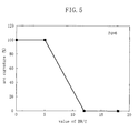
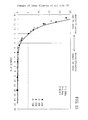
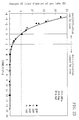
- FIG. 5 shows the relationship between the arc curvature and BW / f.
- the arc curvature in FIG. 5 represents the curving of the arc, marking as 100% the situation that the arc reaches the tube walls, and as 0% the situation that the arc forms a straight line.
- the experiment in FIG. 5 was performed with a configuration in which the value of Pd is 6.
- the value of BW / f increases, the arc curvature decreases, and the downward force suppressing the arc curving becomes stronger.
- BW / f exceeds 10
- the arc curvature becomes 0% and the arc becomes straight (linear).
- the inventors of the present invention found that to strike a balance between the upward force F1 on the arc and the downward force F2 on the arc as described above and suppress arc vibrations, the lamp configuration is required to be as described below, thus arriving at the present invention.
- Equation 6 The term (100BW / f) in Equation 6 is the term of the downward force F 2 on the arc, and the term P 0 d is the term of the upward force F1 on the arc.
- the "100" in the term (100BW/f) is a factor for adjusting the dimensions, and is an experimentally determined factor. That is to say, the 100BW / f of the force F2 suppressing the curving of the arc and the P 0 ⁇ d of the force F1 curving the arc are balanced by the factor 100 multiplied to BW / f, and (100BW/f)-P 0 d is proportional to the curvature of the arc. Therefore, when (100BW/f)-P 0 d becomes large, the curving of the arc becomes large, and when P ⁇ d-10BW/f becomes small, the curving of the arc becomes small.
- Equation 6 the pressure P 0 (MPa) inside the arc tube 1 during steady-state operation is about 10 times the pressure P (MPa) of the enclosed rare gas in the mercury-free metal halide lamp, it is possible to transform Equation 6 into Equation 7. In this case, the factor 10 balances F1 with F2. Equation 7 0 ⁇ (10BW/f)-Pd ⁇ 10
- Equation 7 the pressure P (MPa) of the enclosed rare gas at 20°C was taken.
- the following is a thermodynamic explanation why the pressure P 0 inside the arc tube 1 becomes 10 times the pressure P.
- a rare gas and a metal halide gas are present in the arc tube.
- the temperature at the center portion of the arc is about 5000 to 6000K, and the temperature near the walls of the arc tube is 1000K, so that it can be assumed that the average gas temperature inside the arc tube 1 is about 3000K.
- a temperature of about 3000K during operation is about 10 times the room temperature of 293K, so that it follows from the ideal gas equation that the pressure is about 10 times higher.
- the pressure P of the enclosed rare gas is 1.0MPa
- the pressure P 0 during operation becomes 10MPa.
- the pressure inside the arc tube 1 during operation is shown in FIG. 6.
- the gas pressure of the metal halide is 1MPA, which is 1/10 of that of the rare gas. Therefore, most of the pressure is due to the rare gas, so that it is no particular problem to ignore the influence of the metal halide.
- a configuration can be adopted, that is based on the pressure P of the enclosed rare gas at 20°C.
- Hg gas accounts for about 30%, so that there is the possibility that with a configuration based on the pressure P of the enclosed rare gas at 20°C, the lamp properties during actual operation cannot be reflected.
- configurations based on the pressure P 0 inside the arc tube 1 are preferable over configurations based on the pressure P of the enclosed rare gas at 20°C, because this reflects the properties of the lamp more accurately.
- FIG. 7 schematically shows the configuration of a mercury-free high-intensity discharge lamp operating apparatus 100 according to Embodiment 1.
- FIG. 8 schematically shows the cross-sectional configuration of a high-intensity discharge lamp 11 included in the lamp operating apparatus 100.
- the lamp operating apparatus 100 includes a high-intensity discharge lamp 11 and a ballast 12 for operating the lamp 11.
- the high-intensity discharge lamp 11 includes an arc tube 1 containing luminous material 6 and a pair of electrodes 3 arranged inside the arc tube 1.
- the high-intensity discharge lamp 11 is a metal halide lamp that contains no mercury (Hg) as the luminous material 6 , and is operated horizontally, which means that the straight line connecting the heads of the two electrodes 3 is arranged to be substantially horizontal.
- the ballast 12 shown in FIG. 7 is provided with an alternating current generation means for supplying an alternating current to the pair of electrodes 3 (or to a pair of external leads 5 ).
- the alternating current generation means any suitable alternating current generation means as known in the art can be used.
- the lamp 11 is electrically connected to the ballast 12 with the axis of the pair of electrodes 3 in horizontal orientation, and the connected lamp 11 is operated at a rated power, supplying for example a square alternating current to the lamp 11.
- the configuration of the ballast 12 will be described in more detail.
- the ballast 12 in this embodiment is designed so that the operating frequency and the operating power can be set freely.
- a pulse voltage of about 20(kV) is applied continuously between the electrodes of the lamp. This forms an arc between the electrodes of the lamp, and the lamp 11 begins to operate.
- the voltage between the electrodes decreases to several dozen Volts.
- the ballast 12 supplies a current to the lamp 11 at a pre-set frequency (for example, 50Hz constant).
- the ballast 12 has the function to adjust the lamp current according to the lamp voltage, such that at stationary lamp operation, the preset power is achieved with a square wave of a preset frequency.
- the ballast 12 can also have the function to change the frequency only during the initial period of the operation when the lamp power W is large. Also, in order to absorb variations in the optimum frequency among products, it is also possible that the ballast 12 has the function to provide a temporal change, for example by adjusting the operating frequency.
- the arc tube 1 is made for example of quartz glass, and its internal volume V is about 0.025(cc).
- the distance d between the heads of the pair of electrodes 3 is 4(mm).
- the enclosed material 6 is a metal halide, and the enclosed material 6 does not contain mercury.
- the inner radius of the arc tube 1 in a direction perpendicular to a line connecting the electrodes is about 2.8(mm).
- the arc tube 1 is enclosed by an outer tube 14 , which is fastened to a lamp base 13.
- Each of the pair of electrodes 3 is connected via a metal foil 4 sealed into a side portion of the arc tube 1 to an external lead wire 5.
- the lamp 11 is provided with a magnetic field application means 10 for applying in substantially vertical direction a magnetic field including a component that is substantially perpendicular to the line connecting the heads of the pair of electrodes 3.
- a permanent magnetic is used for the magnetic field application means 10, and a permanent magnet 10 applying a magnetic field B of 4.0 (mT) to the arc is fixed to one of the external lead wires 5.
- this permanent magnet 10 forms a magnetic field whose magnetic force lines are perpendicular.
- the enclosed material 6 that is enclosed into the arc tube 1 is for example trivalent indium iodide (InI 3 ), thallium iodide (T1I), scandium iodide (ScI 3 ) and sodium iodide (NaI).
- InI 3 trivalent indium iodide
- T1I thallium iodide
- ScI 3 scandium iodide
- NaI sodium iodide
- xenon gas which is a rare gas, is enclosed at 1.0(MPa) at 20°C.
- the internal volume of the arc tube 1 is about 0.025cc.
- metal halides are not limited to iodides, and they can also be bromides, chlorides, or other metallic elements or their metallic compounds.
- indium halides preferably InI 3 and/or InI (and most preferably InI 3 ) increase the lamp voltage, so that the lamp can be operated at a lower current, and the ballast can be made smaller, and furthermore, they increase the light emission efficiency, so that it is preferable to include them in the arc tube 1 in view of practical aspects.
- InI 3 InI and TlI are halides with a high vapor pressure, and metal halides (including for example InI 3 ) whose vapor pressure at for example 900°C is at least 1 atm can be used preferably as the enclosed material 6 filled into the metal halide lamp.
- xenon gas was used as the rare gas, but there is no limitation to that, and other rare gases such as argon or krypton as well as their mixtures can be used, too.
- the upward force F1 on the arc is based on the term Pd, it does not depend on the shape or the volume of the arc tube 1. It seems that this is so because factors such as the shape and the volume of the arc tube 1 are already reflected by the pressure P. Therefore, in this embodiment, the volume V of the arc tube was taken to be 0.025(cc), but there is no limitation to this.
- the material constituting the arc tube 1 was shown to be quartz glass, but the material of the arc tube is not limited to this, and can also be alumina, YAG or any other suitable ceramic material, for example.
- the arc tube 1 is enclosed by an outer tube 14, but there is no limitation to this configuration, and other configurations without an outer tube 14 are of course also possible.
- the permanent magnet 10 is fixed to the outer lead wire 5, as long as it is fixed reliably, so that it can form a magnetic field as shown in the present embodiment inside the arc tube. Furthermore, the same effect can also be attained when an electromagnet is used instead of the permanent magnet 10 for the magnetic field application means.
- a ferrite permanent magnet, an alnico magnet, or a rare-earth permanent magnet can be used for example.
- a ferrite permanent magnet is inexpensive and common, so that it is advantageous with regard to costs. Considering the effect that increasing temperature lower the magnetic force, it is preferable that the permanent magnet is arranged at a position where it is not easily susceptible to the heat of the lamp.
- the magnetic force decreases only little when the temperature rises, so that the magnet can be arranged close to the lamp.
- the alnico magnet can be smaller than when using a ferrite permanent magnet. In case of a rare-earth permanent magnet with very high magnetic force, an even smaller magnet can be used.
- the magnetic force lines (polarity of N- and S-pole).
- the magnetic force lines there is no particular limitation to only one permanent magnet or electromagnet, and it is also possible to provide magnets above and below the arc tube 1 .
- the waveform of the current applied by the ballast 12 to the lamp 11 is a square wave, but there is no limitation to this, and it can also be a sine wave or a triangular wave.
- FIG. 9 schematically shows the configuration of an experimental device used to measure variations in the optical output.
- a measurement head 42 of a photometer 40 was placed near the lamp 11 and the change of the optical output from the photometer 40 was observed with an oscilloscope 41, after passing if through a lowpass filter (LPF) in order to cut noise.
- LPF lowpass filter
- the appearance of the curving and the flickering of the arc of the lamp 11 was picked up with a CCD 50, and this image was recorded with a VTR 60 and displayed on a monitor 70, where the curving and the flickering of the arc was observed by a test person.
- a filter 20 was disposed between the lamp 11 and the CCD 50.
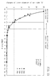
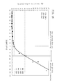
- FIG. 10 is a graph showing the results of examining the flickering by measuring the variations in the optical output.
- the horizontal axis in FIG. 10 marks the value of 10BW / f - P ⁇ d, wherein P (MPa) is the pressure of the enclosed rare gas, whereas the vertical axis marks the variation (%) of the optical output.
- the variation of the optical output is shown as the value (in %) of the difference between the maximum and the minimum of the optical output divided by the average of the optical output.
- the variation of the optical output of the lamp 11 depends on 10BW / f - P ⁇ d.
- 10BW / f - P ⁇ d exceeds 7
- the variation of the optical output exceeds 1(%), reaching a level for which it can be said that variation occurs.
- 10BW / f - P ⁇ d exceeds 10
- the variation of the optical output exceeds 6%.
- 6% were exceeded, the test person perceived this as flickering.
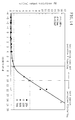
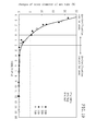
- FIG. 11 is a graph showing the results of examining the occurrence of deformations and devitrification in the arc tube by measuring the changes in the internal diameter of the arc tube.
- the horizontal axis in FIG. 11 marks the value of 10BW / f - P ⁇ d.
- the vertical axis marks the value (in %) of the change of the internal diameter of the arc tube 1 after 1000 hours of intermittent operation, divided by the initial internal diameter of the arc tube 1.
- the change of the internal diameter of the arc tube 1 of the lamp depends on 10BW / f - P ⁇ d. If the value of 10BW / f - P ⁇ d is lower than zero, the change of the internal diameter of the arc tube exceeds 5(%). In this case, it was confirmed that a change in the arc position occurred and another result was that the luminous flux decreased to 70(%) or less of the initial luminous flux and the change of the color temperature exceeded 300(K), and the lifetime characteristics were degraded. Furthermore, although the change of the internal diameter of the arc tube was small, devitrification in the upper portion of the arc tube was observed when the value of 10BW / f - P ⁇ d was lower than 2.
- FIG. 12 and FIG. 13 show the results for the same configuration as for the lamp operating apparatus 100, but with the permanent magnet 10 adjusted such that a magnetic field B of 40(mT) was applied in the arc. Also for the results shown in FIG. 12 and FIG. 13, the flickering and the lifetime characteristics were measured, taking the power W consumed by the lamp 11 during steady-state operation and the operating frequency f during steady-state operation as parameters, as in FIG. 10 and FIG. 11. The measurement was performed setting the power W to the four levels 20, 35, 50 and 70(W), and varying the operating frequency between 30 and 20000 (Hz).
- FIG. 12 is a graph showing the result of examining the flickering by measuring the variation in the optical output, as in FIG. 10.
- the horizontal axis and the vertical axis in FIG. 12 are the same as in FIG. 10.
- the variation of the optical output of the lamp 11 depends on 10BW / f - P ⁇ d, as when the magnetic field is 4(mT).
- 10BW / f - P ⁇ d exceeds 7
- the variation of the optical output nearly exceeds 1(%), reaching a level for which it can be said that variation occurs.
- 10BW / f - P ⁇ d exceeds 10
- the variation of the optical output nearly exceeds 6(%). In this situation, the test person perceived this as flickering.
- FIG. 13 is a graph showing the results of examining the occurrence of deformations and devitrification in the arc tube by measuring the changes in the internal diameter of the arc tube, as in FIG. 11.
- the horizontal axis and the vertical axis in FIG. 13 are as in FIG. 11.
- the change of the inner diameter of the arc tube 1 depends on 10BW / f - P ⁇ d, as when the magnetic field is 4(mT) as shown in FIG. 11. If the value of 10BW / f - P ⁇ d is lower than zero, the change of the internal diameter of the arc tube exceeds 5(%). In this case, it was confirmed that a change in the arc position occurred and another result was that the luminous flux decreased to 70(%) or less of the initial luminous flux and the change of the color temperature exceeded 300(K), and the lifetime characteristics were degraded. Furthermore, although the change of the internal diameter of the arc tube was small, devitrification in the upper portion of the arc tube was observed when the value of 10BW / f - P ⁇ d was lower than 2.
- FIG. 14 and FIG. 15 show the results for the same configuration as for the lamp operating apparatus 100, but with the permanent magnet 10 adjusted such that a magnetic field B of 400(mT) was applied in the arc. Also for the results shown in FIG. 14 and FIG. 15, the flickering and the lifetime characteristics were measured, taking the power W consumed by the lamp 11 during steady-state operation and the operating frequency f during steady-state operation as parameters. The measurement was performed setting the power W to the four levels 20, 35, 50 and 70(W), and varying the operating frequency between 30 and 20000 (Hz).
- FIG. 14 is a graph showing the result of examining the flickering by measuring the variation in the optical output, as in FIG. 10.
- the horizontal axis and the vertical axis in FIG. 12 are the same as in FIG. 10.
- the variation of the optical output of the lamp 11 depends on 10BW / f - P . d, as when the magnetic field is 4(mT) as shown in FIG. 10.
- 10BW / f - P ⁇ d exceeds 7
- the variation of the optical output nearly exceeds 1(%), reaching a level for which it can be said that variation occurs.
- 10BW / f - P ⁇ d exceeds 10
- the variation of the optical output nearly exceeds 6(%). In this situation, the test person perceived this as flickering.
- FIG. 15 is a graph showing the results of examining the occurrence of deformations and devitrification in the arc tube by measuring the changes in the internal diameter of the arc tube, as in FIG. 11.
- the horizontal axis and the vertical axis in FIG. 15 are as in FIG. 11.
- the change of the inner diameter of the arc tube 1 depends on 10BW / f - P ⁇ d, as when the magnetic field is 4(mT) as shown in FIG. 11. If the value of 10BW / f - P ⁇ d is lower than zero, the change of the internal diameter of the arc tube exceeds 5(%). In this case, it was confirmed that a change in the arc position occurred and another result was that the luminous flux decreased to 70(%) or less of the initial luminous flux and the change of the color temperature exceeded 300(K), and the lifetime characteristics were degraded. Furthermore, although the change of the internal diameter of the arc tube was small, devitrification in the upper portion of the arc tube was observed when the value of 10BW / f - P ⁇ d was lower than 2.
- Embodiment 1 has described the characteristics when changing mainly the strength of the magnetic field, whereas this embodiment will describe the characteristics when changing the pressure of the rare gas enclosed in the arc tube 1. Other aspects are as in Embodiment 1 , so that their description has been omitted or simplified.
- the mercury-free high-intensity discharge lamp operating apparatus and the high-intensity discharge lamp of the present embodiment have the same configuration as that of the mercury-free high-intensity discharge lamp operating apparatuses 100 in FIG. 1 and FIG. 2.
- the magnetic field B applied to the arc was fixed at 4.0(mT)
- the pressure P of the xenon gas enclosed in the arc tube 21 was set to 0.1(MPa)
- the flickering and the lifetime characteristics were measured, taking the power W consumed during steady-state operation and the operating frequency f during steady-state operation as parameters.
- the measurement was performed setting the power W to the four levels 20, 35, 50 and 70(W), and varying f between 30 and 20000 (Hz).
- FIG. 16 is a graph showing the results of examining the flickering by measuring the variations in the optical output.
- the horizontal axis and the vertical axis in FIG. 16 are the same as in FIG. 10.
- the variation of the optical output of the lamp 11 depends on 10BW / f - P ⁇ d, as in Embodiment 1.
- 10BW / f - P . d exceeds 7
- the variation of the optical output nearly exceeds 1(%), reaching a level for which it can be said that variation occurs.
- 10BW / f - P ⁇ d exceeds 10
- the variation of the optical output nearly exceeds 6(%). In this situation, the test person perceived flickering.
- FIG. 17 is a graph showing the results of examining the occurrence of deformations and devitrification in the arc tube by measuring the changes in the internal diameter of the arc tube, as in FIG. 11.
- the horizontal axis and the vertical axis in FIG. 17 are the same as in FIG. 11.
- the change of the internal diameter of the arc tube 1 depends on 10BW / f - P ⁇ d, as in Embodiment 1. If the value of 10BW / f - P ⁇ d is lower than zero, the change of the internal diameter of the arc tube nearly exceeds 5(%). In this case, it was confirmed that a change in the arc position occurred and another result was that the luminous flux decreased to 70(%) or less of the initial luminous flux and the change of the color temperature exceeded 300(K), and the lifetime characteristics were degraded. Furthermore, although the change of the internal diameter of the arc tube was small, devitrification in the upper portion of the arc tube was observed when the value of 10BW / f - P ⁇ d was lower than 2.
- FIG. 18 and FIG. 19 show the results for a configuration, in which the pressure P of the xenon gas was set to 2.5(MPa). Also for the results shown in FIG. 18 and FIG. 19, the flickering and the lifetime characteristics were measured, taking the power W consumed by the lamp 11 during steady-state operation and the operating frequency f during steady-state operation as parameters. The measurement was performed setting the power W to the four levels 20, 35, 50 and 70(W), and varying f between 30 and 20000(Hz).
- FIG. 18 is a graph showing the result of examining the flickering by measuring the variation in the optical output, as in FIG. 10.
- the horizontal axis and the vertical axis in FIG. 18 are the same as in FIG. 10.
- the variation of the optical output of the lamp 11 depends on 10BW / f - P ⁇ d, as in Embodiment 1.
- 10BW / f - P d exceeds 7
- the variation of the optical output nearly exceeds 1(%), reaching a level for which it can be said that variation occurs.
- 10BW / f - P ⁇ d exceeds 10
- the variation of the optical output nearly exceeds 6(%). In this situation, the test person perceived flickering.
- FIG. 19 is a graph showing the results of examining the occurrence of deformations and devitrification in the arc tube by measuring the changes in the internal diameter of the arc tube, as in FIG. 11.
- the horizontal axis and the vertical axis in FIG. 19 are the same as in FIG. 11.
- the change of the internal diameter of the arc tube 1 depends on 10BW / f - P . d, as in Embodiment 1. If the value of 10BW / f - P ⁇ d is lower than zero, the change of the internal diameter of the arc tube nearly exceeds 5(%). In this case, it was confirmed that a change in the arc position occurred and another result was that the luminous flux decreased to 70(%) or less of the initial luminous flux and the change of the color temperature exceeded 300(K), and the lifetime characteristics were degraded. Furthermore, although the change of the internal diameter of the arc tube was small, devitrification in the upper portion of the arc tube was observed when the value of 10BW / f - P ⁇ d was lower than 2.
- mercury-free high-intensity discharge lamp operating apparatuses 100 with a value for P of 2.5(MPa) is excellent in terms of the prevention of flickering and the degradation of the lifetime characteristics was attained, but two out of fifteen samples broke within 1000 hours and became inoperable.
- the value of P is set within a range lower than 2.5(MPa).
- the pressure of the enclosed rare gas is 0.5(MPa) or less, the thermal conduction within the arc tube 21 is low so that the enclosed material 6 vaporizes less easily. Therefore, it is preferable that the pressure P of the enclosed rare gas is set within a range exceeding 0.5(MPa).
- the mercury-free high-intensity discharge lamp operating apparatus and the high-intensity discharge lamp of the present embodiment have the same configuration as that of the mercury-free high-intensity discharge lamp operating apparatuses 100 in FIG. 1 and FIG. 2.
- the magnetic field B applied to the arc was fixed at 4.0(mT)
- the pressure P of the xenon gas was set to 1.0(MPa)
- the distance d between the heads of the pair of electrodes 3 was set to 2mm.
- the flickering and the lifetime characteristics were measured, taking the power W consumed during steady-state operation and the operating frequency f during steady-state operation as parameters.
- the measurement was performed setting the power W to the four levels 20, 35, 50 and 70(W), and varying f between 30 and 20000 (Hz).
- FIG. 20 is a graph showing the results of examining the flickering by measuring the variations in the optical output as in FIG. 10.
- the horizontal axis and the vertical axis in FIG. 20 are the same as in FIG. 10.
- FIG. 21 is a graph showing the results of examining the occurrence of deformations and devitrification in the arc tube by measuring the changes in the internal diameter of the arc tube, as in FIG. 11.
- the horizontal axis and the vertical axis in FIG. 21 are the same as in FIG. 11.
- the change of the internal diameter of the arc tube 1 depends on 10BW / f - P ⁇ d, as in Embodiment 1. If the value of 10BW / f - P ⁇ d is lower than zero, the change of the internal diameter of the arc tube nearly exceeds 5(%). In this case, it was confirmed that a change in the arc position occurred and another result was that the luminous flux decreased to 70(%) or less of the initial luminous flux and the change of the color temperature exceeded 300(K), and the lifetime characteristics were degraded. Furthermore, although the change of the internal diameter of the arc tube was small, devitrification in the upper portion of the arc tube was observed when the value of 10BW / f - P ⁇ d was lower than 2.
- the lamp voltage was about 48(V).
- the distance between the electrode heads is larger than 2.0(mm).
- FIG. 22 and FIG. 23 show the results for a configuration in which the distance d between the heads of the pairs of electrodes 3 was set to 6(mm). Also for the results shown in FIG. 22 and FIG. 23, the flickering and the lifetime characteristics were measured, taking the power W consumed by the lamp 11 during steady-state operation and the operating frequency f during steady-state operation as parameters. The measurement was performed setting the power W to the four levels 20, 35, 50 and 70(W), and varying f between 30 and 20000(Hz), such that acoustic resonance effects did not occur. The measurement was performed with a square wave as the waveform of the operating current.
- FIG. 22 is a graph showing the result of examining the flickering by measuring the variation in the optical output, as in FIG. 10.
- the horizontal axis and the vertical axis in FIG. 22 are the same as in FIG. 10.
- the variation of the optical output of the lamp 11 depends on 10BW / f - P ⁇ d, as in Embodiment 1.
- 10BW / f - P ⁇ d exceeds 7
- the variation of the optical output nearly exceeds 1(%), reaching a level for which it can be said that variation occurs.
- 10BW / f - P ⁇ d exceeds 10
- the variation of the optical output nearly exceeds 6(%). In this situation, the test person perceived flickering.
- FIG. 23 is a graph showing the results of examining the occurrence of deformations and devitrification in the arc tube by measuring the changes in the internal diameter of the arc tube, as in FIG. 11.
- the horizontal axis and the vertical axis in FIG. 23 are the same as in FIG. 11.
- the change of the internal diameter of the arc tube 1 depends on 10BW / f - P ⁇ d, as in Embodiment 1. If the value of 10BW / f - P ⁇ d is lower than zero, the change of the internal diameter of the arc tube nearly exceeds 5(%). In this case, it was confirmed a change in the arc position occurred and another result was that the luminous flux decreased to 70(%) or less of the initial luminous flux and the change of the color temperature exceeded 300(K), and that the lifetime characteristics were degraded. Furthermore, although the change of the internal diameter of the arc tube was small, devitrification in the upper portion of the arc tube was observed when the value of 10BW / f - P ⁇ d was lower than 2.
- Embodiment 4 an example of a lighting system including a high-intensity discharge lamp according to the Embodiments 1 to 3 will be described.
- FIG. 24 schematically shows a configuration of a mirror lamp (lighting system) including a high-intensity discharge lamp 11 according to the previous embodiments, a ballast 12, and a reflecting mirror 80 that reflects light emitted by the lamp 11.
- the center of the arc of the lamp 11 is arranged on the optical axis of the reflecting mirror 80.
- the lamp is attached to the reflecting mirror 80 such that a straight line connecting the heads of the two electrodes 3 is oriented in horizontal direction. in that situation, the lamp 11 is connected to the ballast 12.
- the light from the arc can be projected advantageously, and a mercury-free high-intensity discharge lamp operating apparatus (lighting system) with high efficiency can be realized.
- the arc position in the high-intensity discharge lamp can be controlled by adjusting the downward force F2 due to the term (10BW/f) and the upward force F1 due to the term P ⁇ d, so that a system can be easily realized, in which the light distribution of the projected light can be varied.
- metal halide lamps not containing mercury are desirable in view of environmental issues arising when disposing of waste, among metal halide lamps containing mercury, metal halide lamps containing halides of In (indium) are used suitably.
- In has excellent light emission properties, and, as shown in ELECTRIC DISCHARGE LAMPS (p. 218, John F. Waymouth), it is known to effect a thickening of the arc, thus stabilizing the arc.
- the inventors of the present invention have made a test mercury-free metal halide lamp by taking a Sc-Na mercury-containing metal halide lamp and eliminating the mercury, and found that it was not possible to attain the expected light emission characteristics. Then, the inventors made a test metal halide lamp not containing mercury, which had excellent light emission characteristics and in which In was added, which is known to have the effect of stabilizing the arc. Except for the enclosed material 6 , the configuration of this metal halide lamp is the same as that shown in FIG. 1 .
- the distance d between the electrodes was set to about 4.2(mm) and the xenon gas pressure at 20°C was set to 1.4(MPa).
- the internal volume of the arc tube 1 was about 0.025(cc), and the enclosed halide 6 was made of about 0.1mg of trivalent indium iodide InI 3 (mass per unit internal volume of the arc tube: about 4.2mg/cc), about 0.19mg of scandium iodide (mass per unit internal volume of the arc tube: about 8.0mg/cc), and about 0.16mg sodium iodide (mass per unit internal volume of the arc tube: about 6.4mg/cc). Needless to say, the arc tube 1 does not contain mercury.
- This mercury-free metal halide lamp was operated while orienting it such that a straight line connecting the heads of the electrodes of the lamp was arranged vertically (this is referred to as "vertical operation” in the following).
- adding In did not lead to a stabilization of the arc, and on the contrary, destabilized the arc in this mercury-free metal halide lamp. That is to say, the arc became non-stationary, and the optical output of the lamp became instable. Therefore, it was found that the problem occurred that flickering was perceived.
- the inventors of the present invention were successful in stabilizing a mercury-free metal halide lamp containing In by controlling the upward force (buoyancy) F1 inside the arc tube 1, and realized a mercury-free metal halide lamp containing In with a stabilized arc.
- the mercury-free metal halide lamp of the present embodiment has the same configuration as the lamp shown in FIG. 1 .
- the pressure of the enclosed rare gas and the main electrode distance are chosen such that Pd ⁇ 4.6 was satisfied, wherein d(mm) is the distance between the electrodes and P(MPa) is the pressure of the enclosed gas at 20°C.
- the electrode distance d is set to about 4.2(mm) and the pressure of the enclosed xenon gas at 20°C is set to 1.4(MPa).
- auxiliary electrodes for facilitating the lamp operation are not provided, but it is also possible to provide auxiliary electrodes.
- the configuration of providing auxiliary electrodes is not limited to the present embodiment, and can also be adopted in the above-described Embodiments 1 to 4. Needless to say, the distance d between the electrodes when auxiliary electrodes are provided can be the same as the distance between the main electrodes without auxiliary electrodes.
- the distance between the heads of the electrodes 3 in the arc tube 1, that is, the distance d between the electrodes is about 4.2(mm).
- the internal volume of the arc tube 1 is about 0.025(cc), and the arc tube 1 contains a halide 6 made of about 0.1mg of trivalent indium iodide InI 3 (mass per unit internal volume of the arc tube: about 4.2mg/cc), about 0.19mg of scandium iodide (mass per unit internal volume of the arc tube: about 8.0mg/cc), and about 0.16mg of sodium iodide (mass per unit internal volume of the arc tube: about 6.4mg/cc).
- test lamps were produced, filling the arc tube 1 with Xe gas of 0.3MPa (Megapascal), 0.7MPa, 1.0MPa, 1.1MPa and 1.4MPa at room temperature (20°C). A current with a square waveform of 150Hz was supplied to these test lamps, which were vertically operated at 35W lamp power.
- the changes of the optical output were observed with a photometer 40, and the flickering was observed on a monitor 70, with the configuration shown in FIG. 9.
- the distance between the measurement head 42 and the lamp 11 was set to 32cm.
- the variation of the optical output of the lamp 11 depends on P ⁇ d.
- P ⁇ d becomes larger than 2.94
- the optical output starts to vary.
- P ⁇ d becomes larger than 4.6
- the variation of the optical output exceeds 6%. In this situation, the test person perceived this as flickering.
- the arc instability was quantified for lamps 11 with a configuration similar to that of the mercury-free metal halide lamp described above, in which the Xe pressure was set to 1.0MPa (constant) at room temperature, and the distance d between the electrodes was set to 2.0mm, 4.2mm, 4.6mm and 5.0mm. Also in these lamps 11, a current with a square waveform of 150Hz was supplied, and they were vertically operated at 35W lamp power. The results are shown in FIG. 26. As in FIG. 25, the horizontal axis in FIG. 26 marks P ⁇ d and the vertical axis marks the variation of the optical output.
- the variation of the optical output of the lamp 11 depends on P ⁇ d.
- P ⁇ d becomes larger than 4.6
- the variation of the optical output exceeded 6%
- the variation of the optical output was about 6 to 10Hz. In this situation, the test person perceived this as flickering.
- the arc curves upward due to the buoyancy behavior caused by the temperature distribution arising inside the arc tube.
- the inventors of the present invention investigated whether the flickering (arc instability) during the operation of metal halide lamps not containing mercury is affected by the extent of the buoyancy.
- the buoyancy acting on the arc does not only depend on the temperature distribution, and it seems to be necessary to take into account the relationship between the pressure of the rare gas enclosed in the arc tube and the distance between the electrodes.
- Equation 10 F 1 ⁇ ⁇ a d follows from Equation 9.
- ⁇ a can be regarded as the gas pressure and d can be regarded as the distance between the electrodes. Therefore, from the proportional expression of Equation 10 and from the experimental results, it can be seen that the arc becomes instable when the buoyancy (P ⁇ d) becomes large.
- P ⁇ d the buoyancy
- FIG. 28 shows a mercury-free metal halide lamp with this configuration.
- the mercury-free metal halide lamp shown in FIG. 28 is different from the foregoing configuration in that it is horizontally operated and a magnetic field is applied with a permanent magnet 10.
- the permanent magnet 10 is arranged such that magnetic field B at the portion between the electrode heads is oriented in vertical direction.
- the strength of the electric field between the electrode heads is 5.0 to 10.0(mT), and the distance d between the electrodes is 4.6mm.
- test lamps were made for which the Xe pressure inside the arc tube 1 was set to 1.0(MPa) and 1.4(MPa). A current with a square waveform of 150Hz was supplied to the resulting tubes, and the lamps were operated horizontally at 35W lamp power.
- the mercury-free metal halide lamp of the present embodiment is used for a vehicle headlight, then it is desired that the light is instantly on, directly after turning it on, and since the light emission directly after turning on the lamp mainly depends on the rare gas (Xe), it is preferable that the Xe pressure P(MPa) is at least 0.3(MPa). It is even more preferable that it is at least 0.5(MPa).
- the lamp pressure is proportional to the arc length d(mm), so that when the arc length is too short, it is sometimes not possible to attain a suitable arc pressure, such as 60 to 70V. Therefore, it is preferable that the arc length d is at least 2mm, more preferably at least 3mm.
- the values given for the pressure of the xenon gas, the distance between the electrodes, as well as the internal volume of the arc tube 1 and the amounts of scandium iodide and sodium iodide etc. given for the present embodiment are only examples.
- the internal volume of the arc tube 1 for example is not limited to 0.025cc, and the amount of scandium iodide is not limited to 0.19mg.
- xenon gas was enclosed in the arc tube 1 for the purpose of aiding start-up, but considering use of the lamp in a vehicle headlight, xenon gas is only suitable as a rare gas, and it is also possible to include other rare gases, such as argon gas for example, besides the xenon gas. Similarly, the lamp power is not limited to 35W.
- the mercury-free metal halide lamp of the present invention can be devised as a mirror lamp as shown in Embodiment 4.
- the lamps shown in the Embodiments 1 to 5 can be used not only as vehicle headlights, but of course also for other applications, such as general lighting.
- the lamps can be used as the light source in image projection systems, such as projectors using liquid crystals or DMD.
- the lamps can also be used for sports stadiums or floodlights illuminating road signs.
Landscapes
- Discharge Lamps And Accessories Thereof (AREA)
- Circuit Arrangements For Discharge Lamps (AREA)
Applications Claiming Priority (4)
| Application Number | Priority Date | Filing Date | Title |
|---|---|---|---|
| JP2000156308 | 2000-05-26 | ||
| JP2000156308 | 2000-05-26 | ||
| JP2000225013 | 2000-07-26 | ||
| JP2000225013 | 2000-07-26 |
Publications (2)
| Publication Number | Publication Date |
|---|---|
| EP1158567A2 true EP1158567A2 (de) | 2001-11-28 |
| EP1158567A3 EP1158567A3 (de) | 2002-01-16 |
Family
ID=26592695
Family Applications (1)
| Application Number | Title | Priority Date | Filing Date |
|---|---|---|---|
| EP01113019A Withdrawn EP1158567A3 (de) | 2000-05-26 | 2001-05-28 | Betriebsvorrichtung für eine quecksilberfreie Hochleistungsentladungslampe und quecksilberfreie Metallhalogenidlampe |
Country Status (2)
| Country | Link |
|---|---|
| US (1) | US6608444B2 (de) |
| EP (1) | EP1158567A3 (de) |
Cited By (15)
| Publication number | Priority date | Publication date | Assignee | Title |
|---|---|---|---|---|
| EP1172839A2 (de) * | 2000-07-14 | 2002-01-16 | Matsushita Electric Industrial Co., Ltd. | Quecksilberfreie Metallhalogenidlampe |
| WO2004025691A1 (en) * | 2002-09-10 | 2004-03-25 | Philips Intellectual Property & Standards Gmbh | High-pressure discharge lamp with improved color point stability and high luminous efficacy |
| WO2004049391A3 (en) * | 2002-11-25 | 2004-09-02 | Philips Intellectual Property | High-pressure discharge lamp, and method of manufacture thereof |
| US7132797B2 (en) | 2002-12-18 | 2006-11-07 | General Electric Company | Hermetical end-to-end sealing techniques and lamp having uniquely sealed components |
| US7215081B2 (en) | 2002-12-18 | 2007-05-08 | General Electric Company | HID lamp having material free dosing tube seal |
| US7358666B2 (en) | 2004-09-29 | 2008-04-15 | General Electric Company | System and method for sealing high intensity discharge lamps |
| US7378799B2 (en) | 2005-11-29 | 2008-05-27 | General Electric Company | High intensity discharge lamp having compliant seal |
| US7432657B2 (en) | 2005-06-30 | 2008-10-07 | General Electric Company | Ceramic lamp having shielded niobium end cap and systems and methods therewith |
| EP2086001A1 (de) * | 2006-11-09 | 2009-08-05 | Harison Toshiba Lighting Corp. | Metallhalogenidlampe |
| US7615929B2 (en) | 2005-06-30 | 2009-11-10 | General Electric Company | Ceramic lamps and methods of making same |
| US7839089B2 (en) | 2002-12-18 | 2010-11-23 | General Electric Company | Hermetical lamp sealing techniques and lamp having uniquely sealed components |
| US7852006B2 (en) | 2005-06-30 | 2010-12-14 | General Electric Company | Ceramic lamp having molybdenum-rhenium end cap and systems and methods therewith |
| US8002431B2 (en) | 2005-01-18 | 2011-08-23 | Musco Corporation | Apparatus and method for eliminating outgassing of sports lighting fixtures |
| US8035304B2 (en) | 2008-03-06 | 2011-10-11 | General Electric Company | Ceramic high intensity discharge lamp having uniquely shaped shoulder |
| US8299709B2 (en) | 2007-02-05 | 2012-10-30 | General Electric Company | Lamp having axially and radially graded structure |
Families Citing this family (8)
| Publication number | Priority date | Publication date | Assignee | Title |
|---|---|---|---|---|
| DE10129464A1 (de) * | 2001-06-19 | 2003-01-02 | Philips Corp Intellectual Pty | Niederdruckgasentladungslampe mit quecksilberfreier Gasfüllung |
| JP4085801B2 (ja) * | 2002-03-11 | 2008-05-14 | 株式会社デンソー | 放電灯装置 |
| JP4037142B2 (ja) * | 2002-03-27 | 2008-01-23 | 東芝ライテック株式会社 | メタルハライドランプおよび自動車用前照灯装置 |
| JP4086158B2 (ja) * | 2003-12-22 | 2008-05-14 | 株式会社小糸製作所 | 放電ランプ装置用水銀フリーアークチューブ |
| US7633228B2 (en) * | 2005-11-30 | 2009-12-15 | General Electric Company | Mercury-free metal halide discharge lamp |
| US8339044B2 (en) * | 2010-12-28 | 2012-12-25 | General Electric Company | Mercury-free ceramic metal halide lamp with improved lumen run-up |
| JP6241688B1 (ja) | 2016-10-20 | 2017-12-06 | 岩崎電気株式会社 | 高圧ナトリウムランプ照明装置 |
| US10806206B1 (en) | 2020-02-12 | 2020-10-20 | John P. Ryan | Venting system for hats |
Citations (14)
| Publication number | Priority date | Publication date | Assignee | Title |
|---|---|---|---|---|
| JPS5586062A (en) * | 1978-12-22 | 1980-06-28 | Toshiba Corp | Metallic vapor discharge lamp |
| WO1992008240A1 (en) * | 1990-10-25 | 1992-05-14 | Fusion Systems Corporation | High power lamp |
| JPH09161725A (ja) * | 1995-12-11 | 1997-06-20 | Sony Corp | 光源装置およびこれを用いた液晶投射装置 |
| WO1999005699A1 (en) * | 1997-07-23 | 1999-02-04 | Koninklijke Philips Electronics N.V. | Mercury free metal halide lamp |
| EP0940841A2 (de) * | 1998-03-06 | 1999-09-08 | Osram Sylvania Inc. | Wechselstrom HID-Lampe mit magnetischer Ablenkung |
| EP0942454A2 (de) * | 1998-03-13 | 1999-09-15 | Osram Sylvania Inc. | Horizontale HID Fahrzeuglampe mit magnetischer Ablenkung |
| WO2000016360A1 (fr) * | 1998-09-16 | 2000-03-23 | Matsushita Electric Industrial Co.,Ltd | Lampe a l'halogenure d'argent anhydre |
| EP1003204A2 (de) * | 1990-10-25 | 2000-05-24 | Fusion Lighting, Inc. | Lampe mit kontrollierbarer Eigenschaften |
| EP1011126A2 (de) * | 1998-12-14 | 2000-06-21 | Patent-Treuhand-Gesellschaft für elektrische Glühlampen mbH | Metallhalogenidlampe |
| EP1037258A1 (de) * | 1998-02-20 | 2000-09-20 | Matsushita Electric Industrial Co., Ltd. | Quecksilberfreie metallhalogenidlampe |
| EP1063681A2 (de) * | 1999-06-25 | 2000-12-27 | Stanley Electric Co., Ltd. | Metallhalogenidentladungslampen |
| EP1076353A1 (de) * | 1999-08-10 | 2001-02-14 | Patent-Treuhand-Gesellschaft für elektrische Glühlampen mbH | Quecksilberfreie Metallhalogenidlampe |
| US6222320B1 (en) * | 1999-01-20 | 2001-04-24 | Patent Truehand-Gesellschaft Fuer Elektrische Gluelampen Mbh | Metal halide lamp with a starting aid |
| EP1111653A1 (de) * | 1999-12-22 | 2001-06-27 | Matsushita Electric Industrial Co., Ltd. | Hochleistungsentladungslampe, zugehörige Steuervorrichtung und mit einer derartigen Entladungslampe ausgerüstete Leuchtvorrichtung |
Family Cites Families (7)
| Publication number | Priority date | Publication date | Assignee | Title |
|---|---|---|---|---|
| JPH01215639A (ja) | 1988-01-14 | 1989-08-29 | Gte Prod Corp | ビーム位置が制御される車両のヘッドライト |
| JPH11238488A (ja) | 1997-06-06 | 1999-08-31 | Toshiba Lighting & Technology Corp | メタルハライド放電ランプ、メタルハライド放電ランプ点灯装置および照明装置 |
| DE19731168A1 (de) | 1997-07-21 | 1999-01-28 | Patent Treuhand Ges Fuer Elektrische Gluehlampen Mbh | Beleuchtungssystem |
| JP3388539B2 (ja) | 1998-02-20 | 2003-03-24 | 松下電器産業株式会社 | 無水銀メタルハライドランプ |
| JP2000090880A (ja) | 1998-09-16 | 2000-03-31 | Matsushita Electric Ind Co Ltd | メタルハライドランプ |
| JP2000012251A (ja) | 1998-06-26 | 2000-01-14 | Mitsubishi Electric Corp | 放電灯装置 |
| KR20010006751A (ko) | 1999-03-11 | 2001-01-26 | 모리시타 요이찌 | 무수은 메탈핼라이드 램프 |
-
2001
- 2001-05-25 US US09/865,842 patent/US6608444B2/en not_active Expired - Lifetime
- 2001-05-28 EP EP01113019A patent/EP1158567A3/de not_active Withdrawn
Patent Citations (14)
| Publication number | Priority date | Publication date | Assignee | Title |
|---|---|---|---|---|
| JPS5586062A (en) * | 1978-12-22 | 1980-06-28 | Toshiba Corp | Metallic vapor discharge lamp |
| EP1003204A2 (de) * | 1990-10-25 | 2000-05-24 | Fusion Lighting, Inc. | Lampe mit kontrollierbarer Eigenschaften |
| WO1992008240A1 (en) * | 1990-10-25 | 1992-05-14 | Fusion Systems Corporation | High power lamp |
| JPH09161725A (ja) * | 1995-12-11 | 1997-06-20 | Sony Corp | 光源装置およびこれを用いた液晶投射装置 |
| WO1999005699A1 (en) * | 1997-07-23 | 1999-02-04 | Koninklijke Philips Electronics N.V. | Mercury free metal halide lamp |
| EP1037258A1 (de) * | 1998-02-20 | 2000-09-20 | Matsushita Electric Industrial Co., Ltd. | Quecksilberfreie metallhalogenidlampe |
| EP0940841A2 (de) * | 1998-03-06 | 1999-09-08 | Osram Sylvania Inc. | Wechselstrom HID-Lampe mit magnetischer Ablenkung |
| EP0942454A2 (de) * | 1998-03-13 | 1999-09-15 | Osram Sylvania Inc. | Horizontale HID Fahrzeuglampe mit magnetischer Ablenkung |
| WO2000016360A1 (fr) * | 1998-09-16 | 2000-03-23 | Matsushita Electric Industrial Co.,Ltd | Lampe a l'halogenure d'argent anhydre |
| EP1011126A2 (de) * | 1998-12-14 | 2000-06-21 | Patent-Treuhand-Gesellschaft für elektrische Glühlampen mbH | Metallhalogenidlampe |
| US6222320B1 (en) * | 1999-01-20 | 2001-04-24 | Patent Truehand-Gesellschaft Fuer Elektrische Gluelampen Mbh | Metal halide lamp with a starting aid |
| EP1063681A2 (de) * | 1999-06-25 | 2000-12-27 | Stanley Electric Co., Ltd. | Metallhalogenidentladungslampen |
| EP1076353A1 (de) * | 1999-08-10 | 2001-02-14 | Patent-Treuhand-Gesellschaft für elektrische Glühlampen mbH | Quecksilberfreie Metallhalogenidlampe |
| EP1111653A1 (de) * | 1999-12-22 | 2001-06-27 | Matsushita Electric Industrial Co., Ltd. | Hochleistungsentladungslampe, zugehörige Steuervorrichtung und mit einer derartigen Entladungslampe ausgerüstete Leuchtvorrichtung |
Non-Patent Citations (2)
| Title |
|---|
| PATENT ABSTRACTS OF JAPAN vol. 004, no. 133 (E-026), 18 September 1980 (1980-09-18) & JP 55 086062 A (TOSHIBA CORP), 28 June 1980 (1980-06-28) * |
| PATENT ABSTRACTS OF JAPAN vol. 1997, no. 10, 31 October 1997 (1997-10-31) & JP 09 161725 A (SONY CORP), 20 June 1997 (1997-06-20) * |
Cited By (27)
| Publication number | Priority date | Publication date | Assignee | Title |
|---|---|---|---|---|
| EP1172839A3 (de) * | 2000-07-14 | 2006-01-25 | Matsushita Electric Industrial Co., Ltd. | Quecksilberfreie Metallhalogenidlampe |
| EP1172839A2 (de) * | 2000-07-14 | 2002-01-16 | Matsushita Electric Industrial Co., Ltd. | Quecksilberfreie Metallhalogenidlampe |
| CN100361269C (zh) * | 2002-09-10 | 2008-01-09 | 皇家飞利浦电子股份有限公司 | 具有色点稳定性和高发光效率的高压放电灯 |
| WO2004025691A1 (en) * | 2002-09-10 | 2004-03-25 | Philips Intellectual Property & Standards Gmbh | High-pressure discharge lamp with improved color point stability and high luminous efficacy |
| US7642722B2 (en) | 2002-09-10 | 2010-01-05 | Koninklijke Philips Electronics, N.V. | High-pressure discharge lamp with improved color point stability and high luminous efficacy |
| CN100437890C (zh) * | 2002-11-25 | 2008-11-26 | 皇家飞利浦电子股份有限公司 | 高压放电灯及其制造方法 |
| US7498742B2 (en) | 2002-11-25 | 2009-03-03 | Koninklijke Philips Electronics N.V. | High-pressure discharge lamp, and method of manufacture thereof |
| WO2004049391A3 (en) * | 2002-11-25 | 2004-09-02 | Philips Intellectual Property | High-pressure discharge lamp, and method of manufacture thereof |
| US7443091B2 (en) | 2002-12-18 | 2008-10-28 | General Electric Company | Hermetical lamp sealing techniques and lamp having uniquely sealed components |
| US7438621B2 (en) | 2002-12-18 | 2008-10-21 | General Electric Company | Hermetical end-to-end sealing techniques and lamp having uniquely sealed components |
| US7215081B2 (en) | 2002-12-18 | 2007-05-08 | General Electric Company | HID lamp having material free dosing tube seal |
| US7132797B2 (en) | 2002-12-18 | 2006-11-07 | General Electric Company | Hermetical end-to-end sealing techniques and lamp having uniquely sealed components |
| US7839089B2 (en) | 2002-12-18 | 2010-11-23 | General Electric Company | Hermetical lamp sealing techniques and lamp having uniquely sealed components |
| US7892061B2 (en) | 2002-12-18 | 2011-02-22 | General Electric Company | Hermetical lamp sealing techniques and lamp having uniquely sealed components |
| US7358666B2 (en) | 2004-09-29 | 2008-04-15 | General Electric Company | System and method for sealing high intensity discharge lamps |
| US8002431B2 (en) | 2005-01-18 | 2011-08-23 | Musco Corporation | Apparatus and method for eliminating outgassing of sports lighting fixtures |
| US8251767B2 (en) | 2005-01-18 | 2012-08-28 | Musco Corporation | Apparatus and method for eliminating outgassing of sports lighting fixtures |
| US7432657B2 (en) | 2005-06-30 | 2008-10-07 | General Electric Company | Ceramic lamp having shielded niobium end cap and systems and methods therewith |
| US7615929B2 (en) | 2005-06-30 | 2009-11-10 | General Electric Company | Ceramic lamps and methods of making same |
| US7852006B2 (en) | 2005-06-30 | 2010-12-14 | General Electric Company | Ceramic lamp having molybdenum-rhenium end cap and systems and methods therewith |
| US7378799B2 (en) | 2005-11-29 | 2008-05-27 | General Electric Company | High intensity discharge lamp having compliant seal |
| US7977885B2 (en) | 2005-11-29 | 2011-07-12 | General Electric Company | High intensity discharge lamp having compliant seal |
| EP2086001A4 (de) * | 2006-11-09 | 2011-04-06 | Harison Toshiba Lighting Corp | Metallhalogenidlampe |
| US8193711B2 (en) | 2006-11-09 | 2012-06-05 | Harison Toshiba Lighting Corp. | Metal halide lamp |
| EP2086001A1 (de) * | 2006-11-09 | 2009-08-05 | Harison Toshiba Lighting Corp. | Metallhalogenidlampe |
| US8299709B2 (en) | 2007-02-05 | 2012-10-30 | General Electric Company | Lamp having axially and radially graded structure |
| US8035304B2 (en) | 2008-03-06 | 2011-10-11 | General Electric Company | Ceramic high intensity discharge lamp having uniquely shaped shoulder |
Also Published As
| Publication number | Publication date |
|---|---|
| US20020017848A1 (en) | 2002-02-14 |
| EP1158567A3 (de) | 2002-01-16 |
| US6608444B2 (en) | 2003-08-19 |
Similar Documents
| Publication | Publication Date | Title |
|---|---|---|
| US6608444B2 (en) | Mercury-free high-intensity discharge lamp operating apparatus and mercury-free metal halide lamp | |
| JP4536513B2 (ja) | 無水銀メタルハライドランプ | |
| EP1172840A2 (de) | Quecksilberfreie Metallhalogenidlampe | |
| EP1172839A2 (de) | Quecksilberfreie Metallhalogenidlampe | |
| JP2001325918A (ja) | 高圧放電ランプ | |
| JP2009181927A (ja) | 高圧放電ランプシステム、およびそれを用いたプロジェクタ | |
| EP1162865A2 (de) | Entladungslampe hoher Intensität, und Gerät zum Betreiben solch einer Lampe | |
| JP2004288617A (ja) | 高圧放電ランプおよび照明装置 | |
| EP1459607A1 (de) | Verwendung von bogengeradrichtung in hid-lampen, die mit vhf-frequenzen betrieben werden | |
| JP3385010B2 (ja) | 無水銀高輝度放電ランプ点灯装置、および無水銀メタルハライドランプ | |
| JP2007172959A (ja) | メタルハライドランプ | |
| US6479950B2 (en) | High intensity discharge lamp, driving apparatus for high intensity discharge lamp, and high intensity discharge lamp system | |
| US20060226783A1 (en) | Krypton metal halide lamps | |
| CN1623217A (zh) | 高压放电灯 | |
| JP2004349242A (ja) | 高圧放電ランプおよび照明装置 | |
| JP3408519B2 (ja) | 高輝度放電ランプ、高輝度放電ランプの駆動装置、およびこれらを用いた高輝度放電ランプ装置 | |
| EP2654384B1 (de) | Beleuchtungsvorrichtung mit einer entladungslampe | |
| JP2004288606A (ja) | 高圧放電ランプおよび照明装置 | |
| JP3385013B2 (ja) | 高輝度放電灯および高輝度放電灯点灯装置 | |
| JP4048376B2 (ja) | 放電ランプ及びプロジェクター | |
| JP4756878B2 (ja) | セラミック放電ランプ点灯装置 | |
| JP2002093375A (ja) | 無水銀メタルハライドランプ | |
| JP2001167732A (ja) | メタルハライド放電ランプ、メタルハライド放電ランプ点灯装置および照明装置 | |
| WO2006120805A1 (ja) | メタルハライド放電ランプおよびメタルハライド放電ランプシステム | |
| JP2003068248A (ja) | 無水銀メタルハライドランプ |
Legal Events
| Date | Code | Title | Description |
|---|---|---|---|
| PUAI | Public reference made under article 153(3) epc to a published international application that has entered the european phase |
Free format text: ORIGINAL CODE: 0009012 |
|
| AK | Designated contracting states |
Kind code of ref document: A2 Designated state(s): AT BE CH CY DE DK ES FI FR GB GR IE IT LI LU MC NL PT SE TR Kind code of ref document: A2 Designated state(s): DE FR GB |
|
| AX | Request for extension of the european patent |
Free format text: AL;LT;LV;MK;RO;SI |
|
| PUAL | Search report despatched |
Free format text: ORIGINAL CODE: 0009013 |
|
| AK | Designated contracting states |
Kind code of ref document: A3 Designated state(s): AT BE CH CY DE DK ES FI FR GB GR IE IT LI LU MC NL PT SE TR |
|
| AX | Request for extension of the european patent |
Free format text: AL;LT;LV;MK;RO;SI |
|
| 17P | Request for examination filed |
Effective date: 20020326 |
|
| AKX | Designation fees paid |
Free format text: DE FR GB |
|
| 17Q | First examination report despatched |
Effective date: 20030909 |
|
| STAA | Information on the status of an ep patent application or granted ep patent |
Free format text: STATUS: THE APPLICATION IS DEEMED TO BE WITHDRAWN |
|
| 18D | Application deemed to be withdrawn |
Effective date: 20051201 |