EP1156393A2 - Druckmaschine - Google Patents
Druckmaschine Download PDFInfo
- Publication number
- EP1156393A2 EP1156393A2 EP01110279A EP01110279A EP1156393A2 EP 1156393 A2 EP1156393 A2 EP 1156393A2 EP 01110279 A EP01110279 A EP 01110279A EP 01110279 A EP01110279 A EP 01110279A EP 1156393 A2 EP1156393 A2 EP 1156393A2
- Authority
- EP
- European Patent Office
- Prior art keywords
- image
- cylinder
- printing
- width
- printing machine
- Prior art date
- Legal status (The legal status is an assumption and is not a legal conclusion. Google has not performed a legal analysis and makes no representation as to the accuracy of the status listed.)
- Withdrawn
Links
Images

Classifications
-
- G—PHYSICS
- G03—PHOTOGRAPHY; CINEMATOGRAPHY; ANALOGOUS TECHNIQUES USING WAVES OTHER THAN OPTICAL WAVES; ELECTROGRAPHY; HOLOGRAPHY
- G03G—ELECTROGRAPHY; ELECTROPHOTOGRAPHY; MAGNETOGRAPHY
- G03G15/00—Apparatus for electrographic processes using a charge pattern
- G03G15/14—Apparatus for electrographic processes using a charge pattern for transferring a pattern to a second base
- G03G15/16—Apparatus for electrographic processes using a charge pattern for transferring a pattern to a second base of a toner pattern, e.g. a powder pattern, e.g. magnetic transfer
- G03G15/1605—Apparatus for electrographic processes using a charge pattern for transferring a pattern to a second base of a toner pattern, e.g. a powder pattern, e.g. magnetic transfer using at least one intermediate support
-
- G—PHYSICS
- G03—PHOTOGRAPHY; CINEMATOGRAPHY; ANALOGOUS TECHNIQUES USING WAVES OTHER THAN OPTICAL WAVES; ELECTROGRAPHY; HOLOGRAPHY
- G03G—ELECTROGRAPHY; ELECTROPHOTOGRAPHY; MAGNETOGRAPHY
- G03G2215/00—Apparatus for electrophotographic processes
- G03G2215/01—Apparatus for electrophotographic processes for producing multicoloured copies
- G03G2215/0103—Plural electrographic recording members
- G03G2215/0119—Linear arrangement adjacent plural transfer points
Definitions
- the invention relates to a printing press with at least one printing unit, the Image cylinder is driven by friction from an element to which the image is transferred becomes.
- the invention is therefore based on the object of a printing press at the outset mentioned type in such a way that the influence of a change in image content and / or sizes are kept as small as possible.
- the Influence of changes in the printing substrates can be kept as low as possible.
- the object is achieved in that the width of the image cylinder and Element at least as much wider than the maximum width of the image to be transferred is that the speed of the image cylinder essentially changes when the image changes remains constant.
- the additional task is characterized by the features of claims 2 and 4 solved.
- the invention is based on the knowledge that the influence of a change of the above variables on the speed of the image cylinder driven by friction only within certain ranges of the image and / or print substrate width in their relationship to the width of the image cylinder and that driving the image cylinder Elements affects.
- This area is after Not exceeding this minimum difference.
- the use of this area lies the invention. However, this area cannot be output in concrete dimensions as the specific location depends on the design of a machine type depends. Therefore, this range must be determined for each type of machine for example, can be done empirically.
- the invention makes a printing machine available, which with respect to its Register accuracy when changing the above sizes a high consistency having. This means that there are no or significantly less corrections to the register a change of the sizes mentioned is necessary. In this way, the loss of time considerably reduced to take into account changes in the sizes mentioned or reduced to zero. A printing press can often do this seamlessly one printed page after the other from the last printed page to press. The invention therefore makes the performance and register accuracy one Printing press increased, and it is also different in the continuous printing Print pages or short runs can be economically achieved.
- Element that drives the image cylinder by friction around an element of the most varied Act kind. It can also be a cylinder or one with rollers Act band. It may already be the substrate for printing substrates or a act arbitrarily designed image transmission element, which the images into one Print substrate carrier transported further.
- the dimensioning of the width of the image cylinder and the element or elements driving it depends on the image width when in the drive train for the image cylinder only pure image transfers take place. This dimensioning is based on the Print substrate width and thereby becomes larger around the non-printing edge when in this drive train, images are transferred to printing substrates.
- the element that forms the image cylinder drives is the carrier that carries the printing substrates during the printing process and the width of the image cylinder and element is at least as much wider than that maximum width of the printing substrate that the speed of the image cylinder in the event of a change the printing substrate remains essentially constant.
- the width of the image is the width of the print substrate, but the print substrate is either the same width as the image or by a mostly relatively small image-free one Edge is wider.
- the element is an image transfer cylinder. If the drive takes place directly via the image transfer cylinder or cylinders, so is only the image width for dimensioning the width of the image cylinder and the image transfer cylinder. However, it is provided that the image transfer cylinder is driven by the carrier for the printing substrates, so must also be provided here that the width of the image cylinder, image transfer cylinder and carriers are at least as much wider than the maximum width of the printing substrate, that the speed of the image cylinder when changing the sizes mentioned in remains essentially constant. With such power transmissions, at least when a printing substrate is passed between elements, one of the elements is one have certain elasticity which, even without the inclusion of a printing substrate Power transmission guaranteed.
- an impression cylinder is arranged, which is also at least has the above width.
- this is the width that follows the maximum width of the printing substrate.
- the carrier can be provided be that this is driven by a drive roller.
- the measure according to the invention is preferably used in printing machines, where the image is a toner image because of its thickness, profile and size which, in normal machine operation, very often moves from one print page to the next switch.
- printing machines where the image is a toner image because of its thickness, profile and size which, in normal machine operation, very often moves from one print page to the next switch.
- These are mostly printing presses with one device are equipped for digital image generation, usually a device for digital electrostatic imaging, with additional facilities for the Toner and toner removal are available.
- each image is newly generated, so that such a machine preferably in one Area is used in which each printed page from the previous and the following is different.
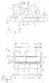
- Fig. 1 shows a printing press 1, which can be designed according to the invention.
- This printing press 1 has at least one printing unit 2, generally four such printing units 2.
- Each printing unit 2 has an image cylinder 3 and an element 4 with an elastic coating, to which the image 5 is transferred.
- the element 4 is an image transfer cylinder 14, which is driven by the carrier 9 or printing substrates 10 located thereon, the force transmission being achieved by a partial wrap.
- a carrier 9 which carries the printing substrates 10 and through a Drive roller 17 is driven.
- Devices 18 for image generation are arranged on the image cylinders 3. It deals in the exemplary embodiment are devices 18 'for digital electrostatic Imaging. Furthermore, 3 devices 19 are located on the image cylinders the toner application and means 20 for removing the non-image transfer cylinder 14 transferred toner.
- the images 5 generated by the devices 18, 18 '- in a multi-color printing press 1 are partial color images of the different printing inks generated for each print page and then by means of an image transmission 15, 15 'from Transfer image cylinder 3 to the image transfer cylinder 14.
- Another image transfer 15, 15 "takes place from the image transfer cylinder 14 onto the printing substrates 10 instead, which are on the carrier 9.
- the arrow 21 shows the transport direction of the Print substrates 10 and arrows 23 show the direction of rotation of the cylinders.
- the Printing substrates 10 are detected by means of a sensor 22 which is controlled by a controller 29 for the control of the devices for image generation 18, 18 'is connected.
- FIG. 2 shows a printing unit 2 of a printing press 1 designed according to the invention in a view perpendicular to the transport direction 21 of the printing substrates 10.
- the same reference numerals correspond to the parts already described for FIG. 1.
- the image cylinders 3 are driven as shown in FIG. 1 via the carrier 9, the image 5 is transferred to the printing substrate 10, it is necessary that the minimum widths 6 'of the image cylinder 3 and of the further image or substrate-carrying elements 4 and 9 have a minimum difference 12 'to the maximum printing substrate width 11.
- Drawn here is a print substrate width 11 'which corresponds to the maximum print substrate width 11.
- the minimum dimension 6 has been chosen for the sake of simplicity pure image transmission 5 in the drive train for the image cylinder 3 with the same dimension drawn as the minimum width 6 'when transferring an image to a printing substrate 10 in such a powertrain.
- the minimum image width 6 ' be correspondingly larger than the minimum image width 6 by the larger width 11 of the Printing substrate 10 compared to the smaller width 7 of the image 5 with the same construction a machine, but with drive of the image cylinder 3 via the carrier 4, invoice to wear.
- the speed 8 of the image cylinder 3 is plotted against the dimensions 25 with respect to the width of the image and printing substrate in relation to the width of the image cylinder and elements to which the image is transferred.
- the speed 24 of the image cylinder 3 is constant.
- the speed curve 26 occurs, this is due to a deformation of the elastic covering of the image transfer cylinder 14.
- the speed curve 27 occurs, if a printing substrate 10 is on the carrier 9, since this is the effective radius of the Image transfer cylinder 14 changes.
- the power transmission takes place via an image transmission point 15 "in which the 5 is applied to a substrate 10, it is necessary that an area 28 ' is avoided in which the speed 8 of the image cylinder 3 is not constant.
- there the minimum width 6 'of the image cylinder 3 essentially increases by the image-free one Edge 13 of the printing substrate 10.
- the elements 4 can be the carrier 9 if this drives the image cylinder 3 directly or it can be both the support 9 act as well as the image transfer cylinder 14 when the machine is constructed in this way is as shown in FIGS. 1 and 2.
- the invention is of course not based on the configuration a printing press, as shown in FIGS. 1 and 2, limited. Except the direct transfer of images 5 from image cylinders 3 to the printing substrates 10, it is also possible that an image transmission element, the images 5 of all image cylinders 3 collects and then transfers them together to a printing substrate 10.
- the Invention is also not based on electrostatic or digital imaging at all limited, the occurs even when transferring color instead of toner mentioned effect of the speed change of image cylinders on the invention can be solved. So there are all types of printing machines according to the invention configurable.
Landscapes
- Physics & Mathematics (AREA)
- General Physics & Mathematics (AREA)
- Electrostatic Charge, Transfer And Separation In Electrography (AREA)
- Control Of Electric Motors In General (AREA)
- Rotary Presses (AREA)
- Discharging, Photosensitive Material Shape In Electrophotography (AREA)
Abstract
Description
- Fig. 1
- ein Beispiel für eine Druckmaschine, die erfindungsgemäß ausgestaltet sein kann,
- Fig. 2.
- ein Druckwerk einer solchen Druckmaschine und
- Fig. 3
- ein Diagramm zur Erläuterung der erfindungsgemäßen Ausgestaltung.
- 1
- Druckmaschine
- 2
- Druckwerk
- 3
- Bildzylinder
- 4
- Element, auf das das Bild übertragen wird
- 5
- Bild
- 6, 6'
- Mindestbreite des Bildzylinders und weiterer bild- oder substrattragender Elemente
- 6
- bei reiner Bildübertragung innerhalb des Antriebsstrangs für den Bildzylinder
- 6'
- bei Bildübertragung auf ein Drucksubstrat innerhalb des Antriebsstrangs für den Bildzylinder
- 7
- maximale Bildbreite
- 7'
- Bildbreite
- 8
- Drehzahl des Bildzylinders
- 9
- Träger, der die Drucksubstrate trägt
- 10
- Drucksubstrate
- 11
- Maximale Drucksubstratbreite
- 11'
- Drucksubstratbreite
- 12
- Mindestdifferenz zwischen maximaler Bildbreite und der Breite des Bildzylinders sowie weiterer bild- oder substrattragender Elemente (9, 14)
- 12'
- Mindestdifferenz zwischen maximaler Drucksubstratbreite und der Breite des Bildzylinders sowie weiterer bild- oder substrattragender Elemente (9, 14)
- 13
- bildfreier Rand des Drucksubstrats
- 14
- Bildübertragungszylinder
- 15
- Bildübertragung
- 15'
- Bildübertragung Bildzylinder - Bildübertragungszylinder
- 15"
- Bildübertragung Bildübertragungszylinder - Drucksubstrat
- 16
- Gegendruckzylinder
- 17
- Antriebsrolle des Trägers
- 18, 18'
- Einrichtung zur Bilderzeugung
- 18'
- Einrichtung zur digitalen elektrostatischen Bilderzeugung
- 19
- Einrichtung für den Tonerauftrag
- 20
- Einrichtung zur Tonerentfernung
- 21
- Pfeil: Transportrichtung der Drucksubstrate
- 22
- Sensor zur Erfassung von Drucksubstraten
- 23
- Pfeil: Drehrichtung der Zylinder
- 24
- Drehzahl des Bildzylinders ohne Tonerauftrag, also ohne Bildübertragung
- 25
- Abmessungen (Breite) von Bild, Drucksubstrat, Bildzylinder und Elementen, auf die das Bild übertragen wird
- 26
- Drehzahlverlauf des Bildzylinders bei reiner Bildübertragung (Tonerübertragung) im Antriebsstrang für den Bildzylinder
- 27
- Drehzahlverlauf, wenn im Antriebsstrang für den Bildzylinder ein Bild auf ein Drucksubstrat übertragen wird
- 28, 28'
- Bereich, in dem die Drehzahl des Bildzylinders nicht konstant ist
- 29
- Steuerung
Claims (9)
- Druckmaschine (1) mit mindestens einem Druckwerk (2), dessen Bildzylinder (3) durch Reibung von einem Element (4) angetrieben wird, auf das das Bild (5) übertragen wird,
dadurch gekennzeichnet, daß die Breite (6, 6') von Bildzylinder (3) und Element (4) mindestens so viel breiter als die maximale Breite (7) des zu übertragenden Bildes (5) ist, daß die Drehzahl (8) des Bildzylinders (3) bei einer Änderung des Bildes (7') im wesentlichen konstant bleibt. - Druckmaschine nach Anspruch 1,
dadurch gekennzeichnet, daß das Element (4) der Träger (9) ist, der während des Druckvorgangs die Drucksubstrate (10) trägt, und die Breite (6') mindestens so viel breiter ist als die maximale Breite (11) des Drucksubstrats (10), daß die Drehzahl (8) des Bildzylinders (2) bei einer Änderung der Drucksubstrate (11') im wesentlichen konstant bleibt. - Druckmaschine nach Anspruch 1,
dadurch gekennzeichnet, daß das Element (4) ein Bildübertragungszylinder (14) ist. - Druckmaschine nach Anspruch 3,
dadurch gekennzeichnet, daß der Bildübertragungszylinder (14) von dem Träger (9) angetrieben wird und die Breite (6') von Bildzylinder (3), Bildübertragungszylinder (14) und Träger (9) mindestens so viel breiter ist als die maximale Breite (11) des Drucksubstrats (10), daß die Drehzahl (8) des Bildzylinders (3) bei einer Änderung der Drucksubstrate im wesentlichen konstant bleibt. - Druckmaschine nach einem der Ansprüche 1 bis 4,
dadurch gekennzeichnet, daß auf der Seite des Trägers (9), der der Bildübertragung (15, 15') gegenüberliegt, ein Gegendruckzylinder (16) angeordnet ist, der ebenfalls mindestens die Breite (6') aufweist. - Druckmaschine nach einem der Ansprüche 1 bis 5,
dadurch gekennzeichnet, daß der Träger (9) über eine Antriebsrolle (17) angetrieben wird. - Druckmaschine nach einem der Ansprüche 1 bis 6,
dadurch gekennzeichnet, daß das Bild (5) ein Tonerbild ist. - Druckmaschine nach einem der Ansprüche 1 bis 7,
dadurch gekennzeichnet, daß sie eine Einrichtung (18, 18') zur digitalen Bilderzeugung aufweist. - Druckmaschine nach Anspruch 8,
dadurch gekennzeichnet, daß sie Einrichtungen zur digitalen elektrostatischen Bilderzeugung (18'), für den Tonerauftrag (19) und zur Tonerentfernung (20) aufweist.
Applications Claiming Priority (2)
| Application Number | Priority Date | Filing Date | Title |
|---|---|---|---|
| US20469600P | 2000-05-17 | 2000-05-17 | |
| US204696P | 2000-05-17 |
Publications (2)
| Publication Number | Publication Date |
|---|---|
| EP1156393A2 true EP1156393A2 (de) | 2001-11-21 |
| EP1156393A3 EP1156393A3 (de) | 2005-02-09 |
Family
ID=22759040
Family Applications (1)
| Application Number | Title | Priority Date | Filing Date |
|---|---|---|---|
| EP01110279A Withdrawn EP1156393A3 (de) | 2000-05-17 | 2001-04-26 | Druckmaschine |
Country Status (2)
| Country | Link |
|---|---|
| EP (1) | EP1156393A3 (de) |
| JP (1) | JP2002006647A (de) |
Cited By (1)
| Publication number | Priority date | Publication date | Assignee | Title |
|---|---|---|---|---|
| US6549745B2 (en) * | 2001-02-16 | 2003-04-15 | Nexpress Solutions Llc | Method and apparatus for controlling overdrive in a frictionally driven system including a conformable member |
Family Cites Families (4)
| Publication number | Priority date | Publication date | Assignee | Title |
|---|---|---|---|---|
| JPH06271130A (ja) * | 1993-03-25 | 1994-09-27 | Toshiba Corp | 画像形成装置 |
| JPH0830123A (ja) * | 1994-07-19 | 1996-02-02 | Ricoh Co Ltd | 画像形成装置 |
| JP3687077B2 (ja) * | 1995-09-29 | 2005-08-24 | 富士ゼロックス株式会社 | 画像形成装置 |
| US6075965A (en) * | 1996-07-29 | 2000-06-13 | Eastman Kodak Company | Method and apparatus using an endless web for facilitating transfer of a marking particle image from an intermediate image transfer member to a receiver member |
-
2001
- 2001-04-26 EP EP01110279A patent/EP1156393A3/de not_active Withdrawn
- 2001-05-17 JP JP2001147605A patent/JP2002006647A/ja active Pending
Cited By (1)
| Publication number | Priority date | Publication date | Assignee | Title |
|---|---|---|---|---|
| US6549745B2 (en) * | 2001-02-16 | 2003-04-15 | Nexpress Solutions Llc | Method and apparatus for controlling overdrive in a frictionally driven system including a conformable member |
Also Published As
| Publication number | Publication date |
|---|---|
| EP1156393A3 (de) | 2005-02-09 |
| JP2002006647A (ja) | 2002-01-11 |
Similar Documents
| Publication | Publication Date | Title |
|---|---|---|
| DE69809000T2 (de) | Druckmaschine mit auf einem Schlitten montierten austauschbaren Plattenzylindern | |
| DE3148449C1 (de) | Verfahren zur Verringerung von Registerfehlern und Druckmaschine zur Durchfuehrung des Verfahrens | |
| DE20122584U1 (de) | Einheit zur Einstellung des Druckbildes in einer Rotationsdruckmaschine | |
| DE2635727B2 (de) | Vorrichtung zur Einhaltung des Passers beim Druck mit einer Mehrfarben-Rollen-Rotationsdruckmaschine | |
| EP3251850A1 (de) | Flexodruckmaschine mit mounter | |
| DE69806403T2 (de) | Druckeinheit | |
| EP1157837A2 (de) | Verfahren und Vorrichtung zur Registereinstellung an einer Mehrfarbendruckmaschine | |
| DE4327646C2 (de) | Breiten-Einstellverfahren für eine Papierbahn sowie damit ausgerüstete lithographische Rotationspresse | |
| EP1291175B1 (de) | Druckzylinder zur Aufnahme mehrerer Bilder | |
| DE102008048659A1 (de) | Vorrichtung und Verfahren zum Ausrichten von Bögen | |
| DE10058841A1 (de) | Verfahren zur Regelung eines Umfangsregisters | |
| EP3016805B1 (de) | Verfahren und vorrichtung zum gegenseitigen anstellen von zwei zylindern in einer druckmaschine | |
| EP0778128B1 (de) | Antrieb für mehrere Übertragungszylinder einer Druckmaschine | |
| EP0676284B1 (de) | Flexodruckmaschine, insbesondere für Mehrfarbendruck | |
| DE102008048278B4 (de) | Verfahren zum Erstellen eines Profils einer Druckgeschwindigkeit einer Druckmaschine | |
| EP1156393A2 (de) | Druckmaschine | |
| DE10232109A1 (de) | Offsetdruckwerk und Offsetdruckverfahren | |
| DE102006018462B4 (de) | Verfahren zum Steuern und/oder Regeln eines Registers in einer Druckmaschine | |
| DE10306663A1 (de) | Druckzylinder | |
| EP1773702A1 (de) | Verfahrenen und vorrichtungen zur positionierung von bahnbearbeitungswerkzeugen bzw. zur voreinstellung einer schnittbreite | |
| EP1156382B1 (de) | Verfahren und Vorrichtung zur Einstellung des Registers bei einer Mehrfarbendruckmaschine | |
| DE102017215110B4 (de) | Vorrichtung zur Kompensation von Fanout | |
| WO2006117291A2 (de) | Verfahren zum steuern und/oder regeln eines registers in einer druckmaschine sowie eine vorrichtung zum steuern und/oder regeln eines umfangsregisters | |
| DE102015200148B4 (de) | Verfahren zur Anpassung mindestens einer Länge einer auf mehreren Druckbogen jeweils gleich groß drucktechnisch auszubildenden Fläche | |
| DE102012002675A1 (de) | Verfahren zur Registerkorrektur bei einer Bahnbearbeitungsmaschine mit einem Verzögerungsabschnitt |
Legal Events
| Date | Code | Title | Description |
|---|---|---|---|
| PUAI | Public reference made under article 153(3) epc to a published international application that has entered the european phase |
Free format text: ORIGINAL CODE: 0009012 |
|
| AK | Designated contracting states |
Kind code of ref document: A2 Designated state(s): AT BE CH CY DE DK ES FI FR GB GR IE IT LI LU MC NL PT SE TR |
|
| AX | Request for extension of the european patent |
Free format text: AL;LT;LV;MK;RO;SI |
|
| RAP1 | Party data changed (applicant data changed or rights of an application transferred) |
Owner name: EASTMAN KODAK COMPANY |
|
| PUAL | Search report despatched |
Free format text: ORIGINAL CODE: 0009013 |
|
| RIC1 | Information provided on ipc code assigned before grant |
Ipc: 7G 03G 15/00 B Ipc: 7G 03G 15/16 A |
|
| AK | Designated contracting states |
Kind code of ref document: A3 Designated state(s): AT BE CH CY DE DK ES FI FR GB GR IE IT LI LU MC NL PT SE TR |
|
| AX | Request for extension of the european patent |
Extension state: AL LT LV MK RO SI |
|
| 17P | Request for examination filed |
Effective date: 20050218 |
|
| AKX | Designation fees paid |
Designated state(s): AT BE CH CY DE DK ES FI FR GB GR IE IT LI LU MC NL PT SE TR |
|
| 17Q | First examination report despatched |
Effective date: 20060614 |
|
| STAA | Information on the status of an ep patent application or granted ep patent |
Free format text: STATUS: THE APPLICATION IS DEEMED TO BE WITHDRAWN |
|
| 18D | Application deemed to be withdrawn |
Effective date: 20070626 |