EP1155901A2 - Fahrgeschwindigkeitsregelsystem mit Steuerung einer Überbrückungskupplung in einem Fahrzeug - Google Patents
Fahrgeschwindigkeitsregelsystem mit Steuerung einer Überbrückungskupplung in einem Fahrzeug Download PDFInfo
- Publication number
- EP1155901A2 EP1155901A2 EP01304272A EP01304272A EP1155901A2 EP 1155901 A2 EP1155901 A2 EP 1155901A2 EP 01304272 A EP01304272 A EP 01304272A EP 01304272 A EP01304272 A EP 01304272A EP 1155901 A2 EP1155901 A2 EP 1155901A2
- Authority
- EP
- European Patent Office
- Prior art keywords
- vehicle speed
- command
- vehicle
- drive torque
- automatic transmission
- Prior art date
- Legal status (The legal status is an assumption and is not a legal conclusion. Google has not performed a legal analysis and makes no representation as to the accuracy of the status listed.)
- Granted
Links
Images


Classifications
-
- B—PERFORMING OPERATIONS; TRANSPORTING
- B60—VEHICLES IN GENERAL
- B60K—ARRANGEMENT OR MOUNTING OF PROPULSION UNITS OR OF TRANSMISSIONS IN VEHICLES; ARRANGEMENT OR MOUNTING OF PLURAL DIVERSE PRIME-MOVERS IN VEHICLES; AUXILIARY DRIVES FOR VEHICLES; INSTRUMENTATION OR DASHBOARDS FOR VEHICLES; ARRANGEMENTS IN CONNECTION WITH COOLING, AIR INTAKE, GAS EXHAUST OR FUEL SUPPLY OF PROPULSION UNITS IN VEHICLES
- B60K31/00—Vehicle fittings, acting on a single sub-unit only, for automatically controlling vehicle speed, i.e. preventing speed from exceeding an arbitrarily established velocity or maintaining speed at a particular velocity, as selected by the vehicle operator
- B60K31/02—Vehicle fittings, acting on a single sub-unit only, for automatically controlling vehicle speed, i.e. preventing speed from exceeding an arbitrarily established velocity or maintaining speed at a particular velocity, as selected by the vehicle operator including electrically actuated servomechanism including an electric control system or a servomechanism in which the vehicle velocity affecting element is actuated electrically
- B60K31/04—Vehicle fittings, acting on a single sub-unit only, for automatically controlling vehicle speed, i.e. preventing speed from exceeding an arbitrarily established velocity or maintaining speed at a particular velocity, as selected by the vehicle operator including electrically actuated servomechanism including an electric control system or a servomechanism in which the vehicle velocity affecting element is actuated electrically and means for comparing one electrical quantity, e.g. voltage, pulse, waveform, flux, or the like, with another quantity of a like kind, which comparison means is involved in the development of an electrical signal which is fed into the controlling means
-
- F—MECHANICAL ENGINEERING; LIGHTING; HEATING; WEAPONS; BLASTING
- F16—ENGINEERING ELEMENTS AND UNITS; GENERAL MEASURES FOR PRODUCING AND MAINTAINING EFFECTIVE FUNCTIONING OF MACHINES OR INSTALLATIONS; THERMAL INSULATION IN GENERAL
- F16H—GEARING
- F16H61/00—Control functions within control units of change-speed- or reversing-gearings for conveying rotary motion ; Control of exclusively fluid gearing, friction gearing, gearings with endless flexible members or other particular types of gearing
- F16H61/66—Control functions within control units of change-speed- or reversing-gearings for conveying rotary motion ; Control of exclusively fluid gearing, friction gearing, gearings with endless flexible members or other particular types of gearing specially adapted for continuously variable gearings
- F16H61/662—Control functions within control units of change-speed- or reversing-gearings for conveying rotary motion ; Control of exclusively fluid gearing, friction gearing, gearings with endless flexible members or other particular types of gearing specially adapted for continuously variable gearings with endless flexible members
- F16H61/66254—Control functions within control units of change-speed- or reversing-gearings for conveying rotary motion ; Control of exclusively fluid gearing, friction gearing, gearings with endless flexible members or other particular types of gearing specially adapted for continuously variable gearings with endless flexible members controlling of shifting being influenced by a signal derived from the engine and the main coupling
- F16H61/66259—Control functions within control units of change-speed- or reversing-gearings for conveying rotary motion ; Control of exclusively fluid gearing, friction gearing, gearings with endless flexible members or other particular types of gearing specially adapted for continuously variable gearings with endless flexible members controlling of shifting being influenced by a signal derived from the engine and the main coupling using electrical or electronical sensing or control means
-
- B—PERFORMING OPERATIONS; TRANSPORTING
- B60—VEHICLES IN GENERAL
- B60W—CONJOINT CONTROL OF VEHICLE SUB-UNITS OF DIFFERENT TYPE OR DIFFERENT FUNCTION; CONTROL SYSTEMS SPECIALLY ADAPTED FOR HYBRID VEHICLES; ROAD VEHICLE DRIVE CONTROL SYSTEMS FOR PURPOSES NOT RELATED TO THE CONTROL OF A PARTICULAR SUB-UNIT
- B60W2510/00—Input parameters relating to a particular sub-units
- B60W2510/10—Change speed gearings
- B60W2510/1005—Transmission ratio engaged
-
- F—MECHANICAL ENGINEERING; LIGHTING; HEATING; WEAPONS; BLASTING
- F16—ENGINEERING ELEMENTS AND UNITS; GENERAL MEASURES FOR PRODUCING AND MAINTAINING EFFECTIVE FUNCTIONING OF MACHINES OR INSTALLATIONS; THERMAL INSULATION IN GENERAL
- F16H—GEARING
- F16H59/00—Control inputs to control units of change-speed-, or reversing-gearings for conveying rotary motion
- F16H59/36—Inputs being a function of speed
- F16H59/46—Inputs being a function of speed dependent on a comparison between speeds
- F16H2059/465—Detecting slip, e.g. clutch slip ratio
- F16H2059/467—Detecting slip, e.g. clutch slip ratio of torque converter
-
- F—MECHANICAL ENGINEERING; LIGHTING; HEATING; WEAPONS; BLASTING
- F16—ENGINEERING ELEMENTS AND UNITS; GENERAL MEASURES FOR PRODUCING AND MAINTAINING EFFECTIVE FUNCTIONING OF MACHINES OR INSTALLATIONS; THERMAL INSULATION IN GENERAL
- F16H—GEARING
- F16H61/00—Control functions within control units of change-speed- or reversing-gearings for conveying rotary motion ; Control of exclusively fluid gearing, friction gearing, gearings with endless flexible members or other particular types of gearing
- F16H61/66—Control functions within control units of change-speed- or reversing-gearings for conveying rotary motion ; Control of exclusively fluid gearing, friction gearing, gearings with endless flexible members or other particular types of gearing specially adapted for continuously variable gearings
- F16H61/662—Control functions within control units of change-speed- or reversing-gearings for conveying rotary motion ; Control of exclusively fluid gearing, friction gearing, gearings with endless flexible members or other particular types of gearing specially adapted for continuously variable gearings with endless flexible members
- F16H2061/66204—Control for modifying the ratio control characteristic
- F16H2061/66218—Control for modifying the ratio control characteristic dependent on control input parameters other than ambient conditions or driver's choice
-
- F—MECHANICAL ENGINEERING; LIGHTING; HEATING; WEAPONS; BLASTING
- F16—ENGINEERING ELEMENTS AND UNITS; GENERAL MEASURES FOR PRODUCING AND MAINTAINING EFFECTIVE FUNCTIONING OF MACHINES OR INSTALLATIONS; THERMAL INSULATION IN GENERAL
- F16H—GEARING
- F16H59/00—Control inputs to control units of change-speed-, or reversing-gearings for conveying rotary motion
- F16H59/50—Inputs being a function of the status of the machine, e.g. position of doors or safety belts
- F16H59/56—Inputs being a function of the status of the machine, e.g. position of doors or safety belts dependent on signals from the main clutch
-
- F—MECHANICAL ENGINEERING; LIGHTING; HEATING; WEAPONS; BLASTING
- F16—ENGINEERING ELEMENTS AND UNITS; GENERAL MEASURES FOR PRODUCING AND MAINTAINING EFFECTIVE FUNCTIONING OF MACHINES OR INSTALLATIONS; THERMAL INSULATION IN GENERAL
- F16H—GEARING
- F16H61/00—Control functions within control units of change-speed- or reversing-gearings for conveying rotary motion ; Control of exclusively fluid gearing, friction gearing, gearings with endless flexible members or other particular types of gearing
- F16H61/14—Control of torque converter lock-up clutches
Definitions
- the present invention relates to a vehicle speed control system for controlling vehicle speed, and more particularly to a control system which controls an automotive vehicle so as to automatically cruise at a set vehicle speed.
- Japanese Patent Provisional Publication No. (Heisei) 7-300026 discloses a vehicle speed control system which is arranged to put an automatic transmission with a torque converter in an un-lockup condition when the automatic transmission of the vehicle is put in a low temperature condition or in a troubled condition, in order to prevent the automatic transmission from generating engine stall for the reason that the operation of a lockup mechanism of the torque converter is degraded by the low temperature condition.
- the response characteristic and the gain characteristic of the vehicle are varied according to whether the automatic transmission is put in a lockup condition or not. That is, if the response characteristic adapted to the lockup condition is employed and if the transmission is put in an un-lockup condition, control stability of the vehicle is degraded by generating a drift between the controlled system and a vehicle speed control system. More specifically, if the response characteristic of the vehicle speed control system is adjusted to the response characteristic in the condition that the transmission is put in the lockup condition, the control characteristic of the control system during the un-lockup condition becomes too quick. Further, if the response characteristic of the transmission during the un-lockup condition is varied by improving the performance of the torque converter of the transmission, the total production cost of the transmission becomes high.
- a vehicle speed control system is for a vehicle which is equipped with an automatic transmission with a lockup torque converter.
- the vehicle control system comprises a detecting section that detects whether the automatic transmission is put in a lockup condition, a correcting section that corrects a command drive torque according to the lock-up condition of the automatic transmission and a controlling section that controls a vehicle speed of the vehicle by commanding the vehicle to generate the corrected command drive torque.
- FIGs. 1 to 12 there is shown a vehicle speed control system according to an embodiment of the present invention.
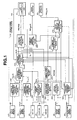
- Fig. 1 shows a block diagram showing a construction of the vehicle speed control system according to the embodiment of the present invention. With reference to Figs. 1 to 12, the construction and operation of the vehicle speed control system according to the present invention will be discussed hereinafter.
- the vehicle speed control system is equipped on a vehicle and is put in a standby mode in a manner that a vehicle occupant manually switches on a system switch (not shown) of the speed control system. Under this standby mode, when a set switch 20 is switched on, the speed control system starts operations.
- the vehicle speed control system comprises a vehicle speed control block 500 which is constituted by a microcomputer and peripheral devices. Blocks in vehicle speed control block 500 represent operations executed by this microcomputer.
- Vehicle speed control block 500 receives signals from a steer angle sensor 100, a vehicle speed sensor 10, the set switch 20, a coast switch 30, an accelerate (ACC) switch 40, an engine speed sensor 80, an accelerator pedal sensor 90, and a continuously variable transmission (CVT) 70. According to the signals received, vehicle speed control block 500 calculates various command values and outputs these command values to CVT 70, a brake actuator 50,and a throttle actuator 60 of the vehicle, respectively, to control an actual vehicle speed at a target vehicle speed.
- CVT 70 continuously variable transmission
- a command vehicle speed determining block 510 of vehicle speed control section 500 calculates a command vehicle speed V COM (t) by each control cycle, such as by 10ms.
- a suffix (t) denotes that the value with the suffix (t) is a valve at the time t and is varied in time series (time elapse). In some graphs, such suffix (t) is facilitated.
- a command vehicle speed maximum value setting block 520 sets a vehicle speed V A (t) as a command vehicle speed maximum value V SMAX (target speed) at time when set switch 20 is switched on.
- Vehicle speed V A (t) is an actual vehicle speed which is detected from a rotation speed of a tire rotation speed by means of a vehicle speed sensor 10.
- command vehicle speed setting block 520 decreases command vehicle speed maximum value V SMAX by 5km/h in reply to one push of coast switch 30. That is, when coast switch 30 is pushed a number n of times (n times), command vehicle speed V SMAX is decreased by n ⁇ 5km/h. Further, when coast switch 30 has been pushed for a time period T (sec.), command vehicle speed V SMAX is decreased by a value T/1(sec.) ⁇ 5km/h.
- command vehicle speed setting block 520 increases command vehicle speed maximum value V SMAX by 5km/h in reply to one push of ACC switch 40. That is, when ACC switch 40 is pushed a number n of times (n times), command vehicle speed maximum value V SMAX is increased by n ⁇ 5km/h. Further, ACC switch 40 has been pushed for a time period T (sec.), command vehicle speed maximum value V SMAX is increased by a value T/1(sec.) ⁇ 5(km/h).
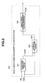
- a lateral acceleration (lateral G) vehicle-speed correction-quantity calculating block 580 receives a steer angle ⁇ (t) from steer angle sensor 100 and vehicle speed V A (t) from vehicle speed sensor 10, and calculates a vehicle speed correction quantity V SUB (t) which is employed to correct the command vehicle speed V COM (t) according to lateral acceleration (hereinafter called lateral-G). More specifically, lateral-G vehicle-speed correction-quantity calculating section 580 comprises a steer angle signal low-pass filter (hereinafter called a steer angle signal LPF block) 581, a lateral-G calculating block 582,and a vehicle speed correction quantity calculation map 583, as shown in Fig. 2.
- a steer angle signal LPF block steer angle signal low-pass filter
- Steer angle signal LPF block 581 receives vehicle speed V A (t) and steer angle ⁇ (t) and calculates a steer angle LPF value ⁇ LPF (t).
- s is a differential operator
- fc is a cutoff frequency of LPF and is determined according to vehicle speed V A (t) as shown by a map showing a relationship between cutoff frequency fc and vehicle speed V A (t) in Fig. 3. As is clear from the map of Fig. 3, cutoff frequency fc becomes smaller as the vehicle speed becomes higher. For example, a cutoff frequency at the vehicle speed 100km/h is smaller than that at the vehicle speed 50km/h.
- W is a wheelbase dimension of the vehicle
- N is a steering gear ratio
- A is a stability factor.
- the equation (2) is employed in case that the lateral G of the vehicle is obtained from the steer angle.
- T YAW is a time constant of the low-pass filter. The time constant T YAW increases as vehicle speed V A (t) increases.
- Vehicle speed correction calculation map 583 calculates a vehicle speed correction quantity V SUB (t) which is employed to correct command vehicle speed V COM (t) according to lateral-G Y G (t).
- Vehicle speed correction quantity V SUB (t) is calculated by multiplying a correction coefficient CC determined from the lateral G and a predetermined variation limit of command vehicle speed V COM (t).
- the predetermined variation limit of the command vehicle speed is equal to the maximum value of a variation (corresponding to acceleration/deceleration) ⁇ V COM (t) of the command vehicle speed shown in Fig. 6.
- V SUB (t) CC ⁇ 0.021 (km/h/10ms)
- the vehicle speed correction quantity V SUB (t) is added as a subtraction term in the calculation process of the command vehicle speed V COM (t) which is employed to control the vehicle speed. Accordingly, command vehicle speed V COM (t) is limited to a smaller value as vehicle correction quantity V SUB (t) becomes larger.
- Correction coefficient CC becomes larger as lateral-G Y G becomes larger, as shown in Fig. 4.
- the reason thereof is that the change of command vehicle speed V COM (t) is limited more as the lateral-G becomes larger.
- correction coefficient CC is set at zero since it is decided that it is not necessary to correct command vehicle speed V COM (t).
- correction coefficient CC is set at a predetermined constant value. That is, the lateral-G never becomes greater than or equal to 0.3G as far as the vehicle is operated under a usual driving condition. Therefore, in order to prevent the correction coefficient CC from being set at an excessively large value when the detection value of the lateral-G erroneously becomes large, the correction coefficient CC is set at such a constant value, such as at 2.
- the command vehicle speed V COM (t) is calculated by adding present vehicle speed V A (t) and command vehicle speed variation ⁇ V COM (t) and by subtracting vehicle speed correction quantity V SUB (t) from the sum of present vehicle speed V A (t) and command vehicle speed variation ⁇ V COM (t).
- command vehicle speed variation ⁇ V COM (t) is greater than vehicle speed correction quantity V SUB (t)
- the present vehicle speed is maintained when the correction coefficient CC is 1.
- the vehicle is accelerated.
- the lateral-G Y G (t) is larger than 0.2, the vehicle is decelerated.
- the command vehicle speed V COM (t) is calculated by subtracting command vehicle speed variation ⁇ V COM (t) and vehicle speed correction quantity V SUB (t) from present vehicle speed V A (t). Therefore, in this case, the vehicle is always decelerated.
- the degree of the deceleration becomes larger as vehicle speed correction quantity V SUB (t) becomes larger. That is, vehicle speed correction quantity V SUB (t) increases according to the increase of the lateral-G Y G (t).
- the above-mentioned value 0.021(km/h/10ms) has been defined on the assumption that the vehicle is traveling on a highway.
- vehicle speed correction quantity V SUB (t) is obtained from the multiple between the correction coefficient CC according to the lateral acceleration and the limit value of the command vehicle speed variation V COM (t). Accordingly, the subtract term (vehicle speed correction quantity) increases according to the increase of the lateral acceleration so that the vehicle speed is controlled so as to suppress the lateral-G.
- the cutoff frequency fc is lowered as the vehicle speed becomes larger. Therefore the time constant TSTR of the LPF is increased, and the steer angle LPF ⁇ LPF (t) is decreased. Accordingly, the lateral acceleration estimated at the lateral-G calculating block 581 is also decreased.
- the vehicle speed correction quantity V SUB (t) which is obtained from the vehicle speed correction quantity calculation map 583, is decreased. Consequently, the steer angle becomes ineffective as to the correction of the command vehicle speed. In other words, the correction toward the decrease of the acceleration becomes smaller due to the decrease of vehicle speed correction quantity V SUB (t).
- ⁇ nSTR (2W /V A ) [Kf • Kr • (1 + A • V A 2 )/m v • I]
- Kf is a cornering power of one front tire
- Kr is a cornering power of one rear tire
- W is a wheelbase dimension
- m V is a vehicle weight
- A is a stability factor
- I is a vehicle yaw inertia moment.
- the characteristic of the natural frequency ⁇ nSTR performs such that the natural frequency ⁇ nSTR becomes smaller and the vehicle responsibility relative to the steer angle degrades as the vehicle speed increases, and that the natural frequency ⁇ nSTR becomes greater and the vehicle responsibility relative to the steer angle is improved as the vehicle speed decreases. That is, the lateral-G tends to be generated according to a steering operation as the vehicle speed becomes lower, and the lateral-G due to the steering operation tends to be suppressed as the vehicle speed becomes higher. Therefore, the vehicle speed control system according to the present invention is arranged to lower the responsibility by decreasing the cutoff frequency fc according to the increase of the vehicle speed so that the command vehicle speed tends not to be affected by the correction due to the steer angle as the vehicle speed becomes higher.
- a command vehicle speed variation determining block 590 receives vehicle speed V A (t) and command vehicle speed maximum value V SMAX and calculates the command vehicle speed variation ⁇ V COM (t) from the map shown in Fig. 6 on the basis of an absolute value
- the map for determining command vehicle speed variation ⁇ V COM (t) is arranged as shown in Fig. 6. More specifically, when absolute value
- command vehicle speed variation ⁇ V COM (t) is decreased as the absolute value of the deviation decreases within a range where the driver can feel an acceleration of the vehicle and the command vehicle speed variation ⁇ V COM (t) does not overshoot maximum value V SMAX of the command vehicle speed.
- command vehicle speed variation ⁇ V COM (t) is set at a constant value which is smaller than acceleration limit ⁇ , such as at 0.06G.
- command vehicle speed variation ⁇ V COM (t) is set at a constant value, such as at 0.03G.
- Command vehicle speed variation determining block 590 monitors vehicle speed correction quantity V SUB (t) outputted from lateral-G vehicle speed correction quantity calculating block 580, and decides that a traveling on a curved road is terminated when vehicle speed correction quantity V SUB (t) is returned to zero after vehicle speed correction quantity V SUB (t) took a value except for zero from zero. Further, command vehicle speed variation determining block 590 detects whether vehicle speed V A (t) becomes equal to maximum value V SMAX of the command vehicle speed.
- the command vehicle speed variation ⁇ V COM (t) is calculated from vehicle speed V A (t) at the moment when it is decided that the traveling on a curved road is terminated, instead of determining the command vehicle speed variation ⁇ V COM (t) by using the map of Fig. 6 on the basis of the absolute value of a deviation between vehicle speed V A (t) and maximum value V SMAX of the command vehicle speed.
- the characteristic employed for calculating the command vehicle speed variation ⁇ V COM (t) under the curve-traveling terminated condition performs a tendency which is similar to that of Fig. 6.
- a horizontal axis denotes vehicle speed V A (t) instead of absolute value
- command vehicle speed variation ⁇ V COM (t) at the termination of the curved road traveling
- vehicle speed V A (t1) at a moment t1 of starting the curved road traveling may be previously stored, and command vehicle speed variation ⁇ V COM (t) may be determined from a magnitude of a difference ⁇ V A between vehicle speed V A (t1) at the moment t1 of the start of the curved road traveling and vehicle speed V A (t2) at the moment t2 of the termination of the curved road traveling.
- the characteristic employed for calculating the command vehicle speed variation ⁇ V COM (t) under this condition performs a tendency which is opposite to that of Fig. 6. More specifically, in this characteristic curve, there is employed a map in which a horizontal axis denotes vehicle speed V A (t) instead of
- the command vehicle speed variation ⁇ V COM (t) is varied according to vehicle speed V A (t) at the moment of termination of the curved road traveling or according to the magnitude of the difference ⁇ V A between vehicle speed V A (t1) at the moment t1 of staring of the curved road traveling and vehicle speed V A (t2) at the moment t2 of the termination of the curved road traveling.
- command vehicle speed variation ⁇ V COM (t) is set small and therefore the acceleration for the vehicle speed control due to the command vehicle speed is decreased.
- This operation functions to preventing a large acceleration from being generated by each curve when the vehicle travels on a winding road having continuous curves such as a S-shape curved road.
- the traveling curve is single and command vehicle speed variation ⁇ V COM (t) is set at a large value. Accordingly, the vehicle is accelerated just after the traveling of a single curved road is terminated, and therefore the driver of the vehicle becomes free from a strange feeling due to the slow-down of the acceleration.
- Command vehicle speed determining block 510 receives vehicle speed V A (t), vehicle speed correction quantity V SUB (t), command vehicle speed variation ⁇ V COM (t) and maximum value V SMAX of the command vehicle speed and calculates command vehicle speed V COM (t) as follows.
- Command vehicle speed V COM (t) is determined from the above-mentioned manner, and the vehicle speed control system controls vehicle speed V A (t) according to the determined command vehicle speed V COM (t).
- a command drive torque calculating block 530 of vehicle speed control block 500 in Fig. 1 receives command vehicle speed V COM (t) and vehicle speed V A (t) and calculates a command drive torque d FC (t).
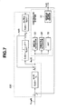
- Fig. 7 shows a construction of command drive torque calculating block 530.
- G V (s) 1/(T V • s + 1) • e (-Lv •s)
- T V is a first-order lag time constant
- L V is a dead time due to a delay of a power train system.
- V A (t) 1/(m V • Rt • s) • e (-Lv•s) • d FC (t)
- Rt is an effective radius of a tire
- m V is a vehicle mass (weight).
- the vehicle model which employs command drive torque d FC (t) as an input and vehicle speed V A (t) as an output, performs an integral characteristic since the equation (11) of the vehicle model is of a 1/s type.
- the controlled system (vehicle) performs a non-linear characteristic which includes a dead time L V due to the delay of the power train system and varies the dead time L V according to the employed actuators and engine
- the vehicle model which employs the command drive torque d FC (t) as an input and vehicle speed V A (t) as an output, can be represented by the equation (11) by means of the approximate zeroing method employing a disturbance estimator.
- C 1 (s) e (-Lv•s) /(T H • s + 1)
- C 2 (s) (m V • Rt • s)/(T H • s + 1)
- d V (t) C 2 (s) • V A (t) - C 1 (s) • d FC (t)
- C 1 (s) and C 2 (s) are disturbance estimators for the approximate zeroing method and perform as a compensator for suppressing the influence due to the disturbance and the modeling.
- d FC (t) C 3 (s) • ⁇ V COM (t) - V A (t) ⁇ - ⁇ C 2 (s) • V A (t) - C 1 (s) • d FC (t) ⁇
- d FC (t) C 3 (s) • ⁇ V COM (t) - V A (t) ⁇ - ⁇ C 2 (s) • V A (t) - C 1 (s) • d FC (t) ⁇
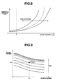
- a drive torque of the vehicle is controlled on the basis of command drive torque d FC (t). More specifically, the command throttle opening is calculated so as to bring actual drive torque d FA (t) closer to command drive torque d FC (t) by using a map indicative of an engine non-linear stationary characteristic. This map is shown in Fig. 8, the relationship represented by this map has been previously measured and stored.
- the vehicle control system operates the transmission and the brake system to ensure the required negative torque.
- the throttle opening, the transmission and the brake system it becomes possible to modify the engine non-linear stationary characteristic into a linearized characteristic.
- vehicle speed control block 500 receives a lockup signal LU S from a controller of CVT 70.
- the lockup signal LU S indicates the lockup condition of CVT 70.
- vehicle speed control block 500 increases the time constant T H employed to represent the compensators C 1 (s) and C 2 (s) as shown in Fig. 7.
- the increase of the time constant T H decreases the vehicle speed control feedback correction quantity, which corresponds to a correction coefficient for keeping a desired response characteristic.
- Command drive torque calculating block 530 shown in Fig. 7 is constructed by compensators C 1 (s) and C 2 (s) for compensating the transfer characteristic of the controlled system and compensator C 3 (s) for achieving a response characteristic previously designed by a designer.
- command drive torque calculating block 530 may be constructed by a pre-compensator C F (s) for compensating so as to ensure a desired response characteristic determined by the designer, a norm model calculating block C R (s) for calculating the desired response characteristic determined by the designer and a feedback compensator C 3 (s)' for compensating a drift quantity (a difference between the target vehicle speed and the actual vehicle speed) with respect to the response characteristic of the norm model calculating section C R (s), as shown in Fig. 12.
- the pre-compensator C F (s) calculates a standard command drive torque d FC1 (t) by using a filter represented by the following equation (17), in order to achieve the transfer function G V (s) of the actual vehicle speed V A (t) with respect to the command vehicle speed V COM (t).
- d FC1 (t) m V • R T • s • V COM (t)/(T V • s + 1)
- K P is a proportion control gain of the feedback compensator C 3 (s)'
- K I is an integral control gain of the feedback compensator C 3 (s)'
- the correction quantity d V (t)' of the drive torque corresponds to an estimated disturbance d V (t) in Fig. 7.
- the feedback gain is set at a smaller value as compared with the feedback gain in the lockup condition. Accordingly, the changing rate of the correction quantity of the command drive torque becomes smaller, and therefore it becomes possible to adapt the response characteristic of the controlled system which characteristic delays under the un-lockup condition of CVT 70 as compared with the characteristic in the lockup condition. Consequently, the stability of the vehicle speed control system is ensured under both of the lockup condition and the un-lockup condition.
- Command gear ratio calculating block 540 receives command drive torque d FC (t), vehicle speed V A (t), the output of coast switch 30,and the output of accelerator pedal sensor 90.
- Command gear ratio calculating block 540 calculates a command gear ratio DRATIO(t), which is a ratio of an input rotation speed and an output rotation speed of CVT 70, on the basis of the received information, and outputs command gear ratio DRATIO(t) to CVT 70 as mentioned later.
- An actual gear ratio calculating block 550 of Fig. 1 calculates an actual gear ratio RATIO(t) (a ratio of an actual input rotation speed and an actual output rotation speed of CVT 70) from the following equation on the basis of the engine rotation speed N E (t) and vehicle speed V A (t) which is obtained by detecting an engine spark signal through engine speed sensor 80.
- RATIO(t) N E (t)/[V A (t) • Gf • 2 ⁇ • Rt]
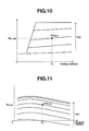
- a target throttle opening calculating block 570 of Fig. 1 calculates a target throttle opening TVO COM from the engine performance map shown in Fig. 11 on the basis of command engine torque TE COM (t) and engine rotation speed N E (t), and outputs the calculated target throttle opening TVO COM to throttle actuator 60.
- a command brake pressure calculating block 630 of Fig. 1 calculates an engine brake torque TE COM ' during a throttle full closed condition from the engine performance map shown in Fig. 11 on the basis of engine rotation speed N E (t). Further, command brake pressure calculating block 630 calculates a command brake pressure REF PBRK (t) from the throttle full-close engine brake torque TE COM ', command engine torque TE COM (t), and the following equation (25):
- REF PBRK (t) (TE COM -TE COM ') • Gm • Gf / ⁇ 4 • (2 • AB • RB • ⁇ B) ⁇
- Gm is a gear ratio of CVT 70
- AB is a wheel cylinder force (cylinder pressure ⁇ area)
- RB is an effective radius of a disc rotor
- ⁇ B is a pad friction coefficient.
- a vehicle speed control suspension deciding block 620 of Fig. 1 receives an accelerator control input APO detected by accelerator pedal sensor 90 and compares accelerator control input APO with a predetermined value.
- the predetermined value is an accelerator control input APO 1 corresponding to a target throttle opening TVO COM inputted from a target throttle opening calculating block 570, that is a throttle opening corresponding to the vehicle speed automatically controlled at this moment.
- accelerator control input APO is greater than a predetermined value, that is, when a throttle opening becomes greater than a throttle opening controlled by throttle actuator 60 due to the accelerator pedal depressing operation of the drive
- vehicle speed control suspension deciding block 620 outputs a vehicle speed control suspending signal.
- Command drive torque calculating block 530 and target throttle opening calculating block 570 initialize the calculations, respectively in reply to the vehicle speed control suspending signal, and the transmission controller of CVT 70 switches the shift-map from a constant speed traveling shift-map to a normal traveling shift map. That is, the vehicle speed control system according to the present invention suspends the constant speed traveling, and starts the normal traveling according to the accelerator pedal operation of the driver.
- the transmission controller of CVT 70 has stored the normal traveling shift map and the constant speed traveling shift map, and when the vehicle speed control system according to the present invention decides to suspend the constant vehicle speed control, the vehicle speed control system commands the transmission controller of CVT 70 to switch the shift map from the constant speed traveling shift map to the normal traveling shift map.
- the normal traveling shift map has a high responsibility characteristic so that the shift down is quickly executed during the acceleration.
- the constant speed traveling shift map has a mild characteristic which impresses a smooth and mild feeling on a driver when the shift map is switched from the constant speed traveling mode to the normal traveling mode.
- Vehicle speed control suspension deciding block 620 stops outputting the vehicle speed control suspending signal when the accelerator control input APO returns to a value smaller than the predetermined value. Further, when the accelerator control input APO is smaller than the predetermined value and when vehicle speed V A (t) is greater than the maximum value V SMAX of the command vehicle speed, vehicle speed control suspension deciding block 620 outputs the deceleration command to the command drive torque calculating block 530.
- command drive torque calculating block 530 basically executes the deceleration control according to the throttle opening calculated at target throttle opening calculating block 570 so as to achieve command drive torque d FC (t).
- command gear ratio calculating block 540 outputs the command gear ratio DRATIO (shift down command) regardless the road gradient, such as traveling on a down slope or a flat road.
- CVT 70 executes the shift down control according to the command gear ratio DRATIO to supply the shortage of the decelerating force.
- command drive torque d FC (t) is not ensured by both the throttle control and the transmission control, and when the vehicle travels on a flat road, the shortage of command drive torque d FC (t) is supplied by employing the brake system.
- the braking control by the brake system is prohibited by outputting a brake control prohibiting signal BP from command drive torque calculating block 530 to a command brake pressure calculating block 630.
- the reason for prohibiting the braking control of the brake system on the down slop is as follows.
- the vehicle speed control system is arranged to execute the deceleration of the vehicle by means of the throttle control and the transmission control without employing the brake system when the vehicle travels on a down slope.
- the deceleration ensured by the transmission control and the throttle control is larger than that only by the throttle control and since the transmission control and the throttle control are executed to smoothly achieve the drive torque on the basis of the command vehicle speed variation ⁇ V COM , it is possible to smoothly decelerate the vehicle while keeping the deceleration degree at the predetermined value.
- a normal non-CVT automatic transmission is employed, a shift shock is generated during the shift down, and therefore even when the larger deceleration is requested, the conventional system employed a non-CVT transmission has executed only the throttle control and has not executed the shift down control of the transmission.
- CVT continuously variable transmission
- K OBS is a constant and T OBS is a time constant.
- vehicle speed V A (t) is a value calculated from the rotation speed of a tire (drive wheel)
- the value of vehicle speed V A (t) corresponds to the rotation speed of the drive wheel.
- drive wheel acceleration ⁇ OBS (t) is a variation (drive wheel acceleration) of the vehicle speed obtained from the derive wheel speed V A (t).
- Vehicle speed control stop deciding block 610 compares drive wheel acceleration ⁇ OBS (t) calculated at drive torque calculating block 600 with the predetermined acceleration limit ⁇ which corresponds to the variation of the vehicle speed, such as 0.2G. When drive wheel acceleration ⁇ OBS (t) becomes greater than the acceleration limit ⁇ , vehicle speed control stop deciding block 610 outputs the vehicle speed control stopping signal to command drive torque calculating block 530 and target throttle opening calculating block 570. In reply to the vehicle speed control stopping signal, command drive torque calculating block 530 and target throttle opening calculating block 570 initialize the calculations thereof respectively. Further, when the vehicle speed control is once stopped, the vehicle speed control is not started until set switch 20 is again switched on.
- the invention is not limited to this and may be arranged such that the stop decision is made when a difference between the command vehicle variation ⁇ V COM and drive wheel acceleration ⁇ OBS (t) becomes greater than a predetermined value.
- Command vehicle speed determining block 510 of Fig. 1 decides whether V SMAX ⁇ V A , that is, whether the command vehicle speed V COM (t) is greater than vehicle speed V A (t) and is varied to the decelerating direction.
- command vehicle speed command control value at each time until the actual vehicle speed reaches the target vehicle speed
- time variation change rate
- the vehicle speed control system is arranged to execute a control for bringing an actual inter-vehicle distance closer to a target inter-vehicle distance so as to execute vehicle traveling while keeping a target inter-vehicle distance set by a driver with respect to a preceding vehicle
- the vehicle speed control system is arranged to set the command vehicle speed so as to keep the target inter-vehicle distance.
Applications Claiming Priority (2)
| Application Number | Priority Date | Filing Date | Title |
|---|---|---|---|
| JP2000143575 | 2000-05-16 | ||
| JP2000143575A JP3678114B2 (ja) | 2000-05-16 | 2000-05-16 | 車速制御装置 |
Publications (4)
| Publication Number | Publication Date |
|---|---|
| EP1155901A2 true EP1155901A2 (de) | 2001-11-21 |
| EP1155901A3 EP1155901A3 (de) | 2005-06-01 |
| EP1155901B1 EP1155901B1 (de) | 2008-11-05 |
| EP1155901B8 EP1155901B8 (de) | 2009-03-11 |
Family
ID=18650374
Family Applications (1)
| Application Number | Title | Priority Date | Filing Date |
|---|---|---|---|
| EP01304272A Expired - Lifetime EP1155901B8 (de) | 2000-05-16 | 2001-05-14 | Fahrgeschwindigkeitsregelsystem mit Steuerung einer Überbrückungskupplung in einem Fahrzeug |
Country Status (4)
| Country | Link |
|---|---|
| US (1) | US6746368B2 (de) |
| EP (1) | EP1155901B8 (de) |
| JP (1) | JP3678114B2 (de) |
| DE (1) | DE60136411D1 (de) |
Families Citing this family (7)
| Publication number | Priority date | Publication date | Assignee | Title |
|---|---|---|---|---|
| JP3648739B2 (ja) * | 2002-03-18 | 2005-05-18 | トヨタ自動車株式会社 | 動力出力装置およびこれを搭載する自動車 |
| DE10231360A1 (de) * | 2002-07-11 | 2004-01-22 | Robert Bosch Gmbh | Verfahren zur Regelung der Geschwindigkeit eines Fahrzeugs |
| JP3900049B2 (ja) | 2002-09-12 | 2007-04-04 | トヨタ自動車株式会社 | 車両用自動変速機の油圧制御装置 |
| JP4245039B2 (ja) * | 2006-11-17 | 2009-03-25 | トヨタ自動車株式会社 | 車両用シート制御システム |
| US8055427B2 (en) * | 2008-12-18 | 2011-11-08 | GM Global Technology Operations LLC | Method and apparatus for speed-limit following cruise control |
| JP5657996B2 (ja) * | 2010-10-29 | 2015-01-21 | アイシン精機株式会社 | 運動量制御装置 |
| EP2994669B1 (de) * | 2013-05-07 | 2020-08-05 | Allison Transmission, Inc. | System und verfahren zur optimierung des herunterschaltens eines getriebes während einer fahrzeugverlangsamung |
Citations (2)
| Publication number | Priority date | Publication date | Assignee | Title |
|---|---|---|---|---|
| JPH07300026A (ja) | 1994-05-06 | 1995-11-14 | Nissan Motor Co Ltd | 車両用定速走行制御装置 |
| JP2000143575A (ja) | 1998-09-11 | 2000-05-23 | Central Glass Co Ltd | クロロフルオロアセトン類の製造方法 |
Family Cites Families (13)
| Publication number | Priority date | Publication date | Assignee | Title |
|---|---|---|---|---|
| JPS60175855A (ja) * | 1984-02-23 | 1985-09-10 | Nissan Motor Co Ltd | 自動変速機の変速シヨツク軽減装置 |
| US5213186A (en) * | 1990-11-30 | 1993-05-25 | Toyota Jidosha Kabushiki Kaisha | Control system and method for automatic transmission |
| JP2887948B2 (ja) * | 1991-06-26 | 1999-05-10 | 株式会社デンソー | 車両用速度制御装置 |
| JP2993264B2 (ja) * | 1992-03-10 | 1999-12-20 | トヨタ自動車株式会社 | 自動変速機付車両用内燃機関の過給制御装置 |
| JP3010962B2 (ja) * | 1993-03-10 | 2000-02-21 | 日産自動車株式会社 | 自動変速機搭載車のフューエルカット制御装置 |
| JPH07277038A (ja) * | 1994-04-11 | 1995-10-24 | Nippondenso Co Ltd | 車両制御装置 |
| KR0156349B1 (ko) * | 1994-06-27 | 1998-10-15 | 쭈지 요시후미 | 무단 변속기의 유압 제어 장치 |
| JPH08178054A (ja) * | 1994-12-26 | 1996-07-12 | Honda Motor Co Ltd | 自動車の制御装置 |
| US5743829A (en) * | 1995-02-22 | 1998-04-28 | Honda Giken Kogyo Kabushiki Kaisha | Control system for vehicle automatic transmission |
| JPH09105454A (ja) * | 1995-10-12 | 1997-04-22 | Jatco Corp | 自動変速機の制御方法および制御装置 |
| JP3496410B2 (ja) * | 1996-10-30 | 2004-02-09 | 日産自動車株式会社 | 自動変速機のロックアップ時ライン圧制御装置 |
| JPH11294547A (ja) * | 1998-04-07 | 1999-10-29 | Hitachi Ltd | 車両用自動変速の制御装置および制御方法 |
| JP3635946B2 (ja) * | 1998-11-06 | 2005-04-06 | 日産自動車株式会社 | トルクコンバータのスリップ制御装置 |
-
2000
- 2000-05-16 JP JP2000143575A patent/JP3678114B2/ja not_active Expired - Fee Related
-
2001
- 2001-05-14 EP EP01304272A patent/EP1155901B8/de not_active Expired - Lifetime
- 2001-05-14 US US09/853,705 patent/US6746368B2/en not_active Expired - Fee Related
- 2001-05-14 DE DE60136411T patent/DE60136411D1/de not_active Expired - Fee Related
Patent Citations (2)
| Publication number | Priority date | Publication date | Assignee | Title |
|---|---|---|---|---|
| JPH07300026A (ja) | 1994-05-06 | 1995-11-14 | Nissan Motor Co Ltd | 車両用定速走行制御装置 |
| JP2000143575A (ja) | 1998-09-11 | 2000-05-23 | Central Glass Co Ltd | クロロフルオロアセトン類の製造方法 |
Also Published As
| Publication number | Publication date |
|---|---|
| US6746368B2 (en) | 2004-06-08 |
| JP3678114B2 (ja) | 2005-08-03 |
| EP1155901B8 (de) | 2009-03-11 |
| US20010046926A1 (en) | 2001-11-29 |
| DE60136411D1 (de) | 2008-12-18 |
| EP1155901A3 (de) | 2005-06-01 |
| JP2001322451A (ja) | 2001-11-20 |
| EP1155901B1 (de) | 2008-11-05 |
Similar Documents
| Publication | Publication Date | Title |
|---|---|---|
| EP1204541B1 (de) | Fahrgeschwindigkeitsregelsystem eines fahrzeugs | |
| EP1194308B1 (de) | Gangschalten bei sollgeschwindigkeitsabsenkung in einem fahrgeschwindigkeitsreglungssystem | |
| US6671607B2 (en) | Vehicle speed control system | |
| KR100459349B1 (ko) | 차량 속도 및 차량간 거리를 제어하기 위한 시스템 및 방법 | |
| KR100459350B1 (ko) | 차량 속도 및 차량간 거리를 제어하기 위한 시스템 및 방법 | |
| US6746368B2 (en) | Vehicle speed control system for automotive vehicle | |
| JP3613138B2 (ja) | 車間距離制御装置 | |
| JP3794242B2 (ja) | 車速制御装置 | |
| JP3695284B2 (ja) | 車速制御装置 | |
| JP3680701B2 (ja) | 車速制御装置 | |
| JP4223173B2 (ja) | 車間距離制御装置 | |
| JP3698014B2 (ja) | 車速制御装置 | |
| JP3780820B2 (ja) | 車速制御装置 | |
| JP3695285B2 (ja) | 車間距離制御装置 | |
| JP3603748B2 (ja) | 車速制御装置 | |
| JP2001322453A (ja) | 車速制御装置 | |
| JP2003112537A (ja) | 車速制御装置 |
Legal Events
| Date | Code | Title | Description |
|---|---|---|---|
| PUAI | Public reference made under article 153(3) epc to a published international application that has entered the european phase |
Free format text: ORIGINAL CODE: 0009012 |
|
| 17P | Request for examination filed |
Effective date: 20010530 |
|
| AK | Designated contracting states |
Kind code of ref document: A2 Designated state(s): AT BE CH CY DE DK ES FI FR GB GR IE IT LI LU MC NL PT SE TR |
|
| AX | Request for extension of the european patent |
Free format text: AL;LT;LV;MK;RO;SI |
|
| PUAL | Search report despatched |
Free format text: ORIGINAL CODE: 0009013 |
|
| AK | Designated contracting states |
Kind code of ref document: A3 Designated state(s): AT BE CH CY DE DK ES FI FR GB GR IE IT LI LU MC NL PT SE TR |
|
| AX | Request for extension of the european patent |
Extension state: AL LT LV MK RO SI |
|
| AKX | Designation fees paid |
Designated state(s): DE FR GB |
|
| 17Q | First examination report despatched |
Effective date: 20060203 |
|
| GRAP | Despatch of communication of intention to grant a patent |
Free format text: ORIGINAL CODE: EPIDOSNIGR1 |
|
| GRAC | Information related to communication of intention to grant a patent modified |
Free format text: ORIGINAL CODE: EPIDOSCIGR1 |
|
| GRAS | Grant fee paid |
Free format text: ORIGINAL CODE: EPIDOSNIGR3 |
|
| GRAA | (expected) grant |
Free format text: ORIGINAL CODE: 0009210 |
|
| AK | Designated contracting states |
Kind code of ref document: B1 Designated state(s): DE FR GB |
|
| REG | Reference to a national code |
Ref country code: GB Ref legal event code: FG4D |
|
| REF | Corresponds to: |
Ref document number: 60136411 Country of ref document: DE Date of ref document: 20081218 Kind code of ref document: P |
|
| RIN2 | Information on inventor provided after grant (corrected) |
Inventor name: ISHIZU, TAKESHI Inventor name: INO, JUNSUKE Inventor name: SUDO, HIDEKI Inventor name: ADACHI, KAZUTAKA,INPERIARUYOKOHAMABEIBYU 402 |
|
| PGFP | Annual fee paid to national office [announced via postgrant information from national office to epo] |
Ref country code: DE Payment date: 20090511 Year of fee payment: 9 Ref country code: FR Payment date: 20090515 Year of fee payment: 9 |
|
| PLBE | No opposition filed within time limit |
Free format text: ORIGINAL CODE: 0009261 |
|
| STAA | Information on the status of an ep patent application or granted ep patent |
Free format text: STATUS: NO OPPOSITION FILED WITHIN TIME LIMIT |
|
| 26N | No opposition filed |
Effective date: 20090806 |
|
| PGFP | Annual fee paid to national office [announced via postgrant information from national office to epo] |
Ref country code: GB Payment date: 20100329 Year of fee payment: 10 |
|
| REG | Reference to a national code |
Ref country code: FR Ref legal event code: ST Effective date: 20110131 |
|
| PG25 | Lapsed in a contracting state [announced via postgrant information from national office to epo] |
Ref country code: DE Free format text: LAPSE BECAUSE OF NON-PAYMENT OF DUE FEES Effective date: 20101201 |
|
| PG25 | Lapsed in a contracting state [announced via postgrant information from national office to epo] |
Ref country code: FR Free format text: LAPSE BECAUSE OF NON-PAYMENT OF DUE FEES Effective date: 20100531 |
|
| GBPC | Gb: european patent ceased through non-payment of renewal fee |
Effective date: 20110514 |
|
| PG25 | Lapsed in a contracting state [announced via postgrant information from national office to epo] |
Ref country code: GB Free format text: LAPSE BECAUSE OF NON-PAYMENT OF DUE FEES Effective date: 20110514 |