EP1154949B1 - Schutzeinrichtung an aufzugstüren - Google Patents
Schutzeinrichtung an aufzugstüren Download PDFInfo
- Publication number
- EP1154949B1 EP1154949B1 EP00902531A EP00902531A EP1154949B1 EP 1154949 B1 EP1154949 B1 EP 1154949B1 EP 00902531 A EP00902531 A EP 00902531A EP 00902531 A EP00902531 A EP 00902531A EP 1154949 B1 EP1154949 B1 EP 1154949B1
- Authority
- EP
- European Patent Office
- Prior art keywords
- door
- sliding door
- bristles
- protection device
- doors
- Prior art date
- Legal status (The legal status is an assumption and is not a legal conclusion. Google has not performed a legal analysis and makes no representation as to the accuracy of the status listed.)
- Expired - Lifetime
Links
- 239000000463 material Substances 0.000 claims description 3
- 230000035807 sensation Effects 0.000 claims 2
- 238000010276 construction Methods 0.000 claims 1
- 239000002184 metal Substances 0.000 claims 1
- 239000011368 organic material Substances 0.000 claims 1
- 229920002994 synthetic fiber Polymers 0.000 claims 1
- 239000011521 glass Substances 0.000 abstract description 16
- 230000011514 reflex Effects 0.000 abstract 1
- 230000001681 protective effect Effects 0.000 description 12
- 230000000694 effects Effects 0.000 description 5
- 208000002193 Pain Diseases 0.000 description 2
- 230000000284 resting effect Effects 0.000 description 2
- 238000004026 adhesive bonding Methods 0.000 description 1
- 238000009411 base construction Methods 0.000 description 1
- 230000015572 biosynthetic process Effects 0.000 description 1
- 230000001419 dependent effect Effects 0.000 description 1
- 238000011161 development Methods 0.000 description 1
- 230000018109 developmental process Effects 0.000 description 1
- 239000011440 grout Substances 0.000 description 1
- 230000001939 inductive effect Effects 0.000 description 1
- 238000009434 installation Methods 0.000 description 1
- 238000012423 maintenance Methods 0.000 description 1
- 230000003287 optical effect Effects 0.000 description 1
- 230000000069 prophylactic effect Effects 0.000 description 1
- 230000035939 shock Effects 0.000 description 1
Images
Classifications
-
- E—FIXED CONSTRUCTIONS
- E06—DOORS, WINDOWS, SHUTTERS, OR ROLLER BLINDS IN GENERAL; LADDERS
- E06B—FIXED OR MOVABLE CLOSURES FOR OPENINGS IN BUILDINGS, VEHICLES, FENCES OR LIKE ENCLOSURES IN GENERAL, e.g. DOORS, WINDOWS, BLINDS, GATES
- E06B7/00—Special arrangements or measures in connection with doors or windows
- E06B7/28—Other arrangements on doors or windows, e.g. door-plates, windows adapted to carry plants, hooks for window cleaners
- E06B7/36—Finger guards or other measures preventing harmful access between the door and the door frame
Definitions
- the present invention relates to a sliding door, in particular an elevator door, with a protective device against pinching, according to the preamble of claim 1.
- Document US A 5794745 also discloses a device for Protection against pinching in a sliding door, the Device a fixed to a door frame brush row having. The brush row is back to the door frame arranged perpendicular to the shift.
- the invention is characterized i.a. characterized by that Bristle ends of parallel to the glass surfaces running Bristles from the vertical air gap between door jambs and Sliding door and between the door and the door a bit and have an education when touching through a The hand resting on the door generates a stinging stimulus, which immediate retraction of the hand entails and so on Pinching the hand prevented in time.
- a thin clamping profile with bristles is for the Elevator users not or hardly visible, at one Door post back and telescopic doors in addition to the Rear side of a door leading edge profile arranged and it will be the vertical air gap between the Door post back and the door leaf surface, or between Door and door wings filled with bristles, the same device for the landing door and for the Cabin door is used.
- the clamping profile with the bristles forms a continuous vertical row of brushes, which is in the whole range of securing zones a complete protection against pinching offers.
- the bristles filling the vertical air gap run Slow to the door leaf surface and touch them only with their Long sides, which is the creation of scratch marks on the Excludes door leaves.
- a sting-inducing formation of bristle ends is made by bevel cuts, pointed shapes or very thin, short and stiff bristles are achieved.
- the material for the bristles can be of organic or inorganic nature of any color.
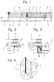
- the shown landing door is a telescopic door, consisting of a first door 1 and a second Door 2, which has an access opening between a right Door post 6 and a left door jamb 7 not one Close completely closed door frame.
- the Door 1 and 2 run in
- Traffic Resultsnuten 4 a Threshold profiles 3 and consist essentially each one Door base construction 8, a glass surface 9 and a Door leading edge profile 10.
- a door entry threshold is at 5 designated.
- the row of brushes 11 in a vertical Air gap 12 between the first door 1 and the right Door post 6 is arranged and consists of a clamping profile 11.1 in which bristles 11.2 are taken with bristle ends 11.3.
- the brush row 11 is not with the clamping profile 11.1 at the visible back of the right door jamb 6 attached.
- the Fixing the clamping profile 11.2 on the back surface of the right door jamb 6 can by gluing, riveting, Screws etc. take place.
- the bristle ends 11.3 are in the Corner between the glass surface 9 and the visible side surface the right door jamb 6 slightly protruding.
- the Vorstehmass can be provided about two to four mm.
- the thickness of the clamping profile 11.1 is about three to four mm and is thus one to two mm smaller than the vertical air gap 12.
- the clamping profile 11.1 must not touch the glass surface 9.
- FIG 3 shows the arrangement of the brush row 11 in one Air gap 13 between the rear of the Door leading edge profile 10 of the first door leaf 1 and the Glass surface 9 of the second door leaf 2.
- the brush row 11 is at the back of the door leading edge profile 10 of the first Door leaf 1 attached.
- the clamping profile 11.1 and the Vorstehmass have the same dimensions as before described on.
- Elevators with glass doors create an attractive effect Children and adolescents, because they as a showcase one Insight into a usually hidden and interesting grant technical support.
- To the mirror effect the shiny glass surface 9 to go around interested viewers often with their heads and hands to the Glass surface 9 of a door leaf 1 or 2 and touch them.
- the elevator door suddenly opens very much fast and tears the viewer in the direction of opening the hands resting on the doors 1 and / or 2 sideways with.
- At least one hand of the Observer in contact with the bristle ends 11.3 a Brush row 11.
- By the impact contact with the Bristle ends 11.3 produces stinging causes a reflexive Pull back the appropriate hand, bringing a pinch the same is avoided.
- the one with the shock touch Connected Stech Grande is perceived as unpleasant, which in addition to the protective effect at least partially even one prophylactic effect against future dangerous Behavior is present.
- the use of the present protective device is limited not on the example shown. So is also provided, the Guard on each type of left or right to use right sliding doors, such as even with simple center doors and telescopic doors with one-sided or centering arrangement with two or more door leaves (1, 2, Vietnamese) per page. Furthermore, the inventive Guard if required even with non-transparent Door leaves 1, 2 ... are used. The installation of the The device according to the invention can also be used with manual actuation Sliding doors of all kinds are made.
- the protective device can also be used in an adapted form automatic vertical slides of small goods lifts and be installed and practice the same there Protective effect.
Landscapes
- Engineering & Computer Science (AREA)
- Civil Engineering (AREA)
- Structural Engineering (AREA)
- Elevator Door Apparatuses (AREA)
- Packaging Of Machine Parts And Wound Products (AREA)
- Power-Operated Mechanisms For Wings (AREA)
Description
Claims (7)
- Schiebetür, insbesondere eine Aufzugstür, mit einer Schutzeinrichtung zum Schutz gegen Einklemmen, wobei die Schiebetür einen Türrahmen (5, 6) und mindestens einen Türflügel (1) aufweist, die mit gegenseitigem Abstand einen Luftspalt bilden, wobei die Schutzeinrichtung eine an dem Türrahmen und/oder an dem Türflügel der Schiebetür festgelegte Bürstenreihe (11) aufweist, die den jeweils gegenseitigen Abstand überbrückt,
dadurch gekennzeichnet, dass freie Borstenenden (11.3) von parallel zur Verschieberichtung verlaufenden Borsten (11.2) der Bürstenreihe (11) so ausgebildet oder angeordnet sind, dass die freien Borstenenden (11.3) über den Türrahmen (6, 7) und/oder über den Türflügel (1) der Schiebetür überstehen. - Schiebetür nach Anspruch 1,
dadurch gekennzeichnet, dass die Borsten (11.2) der Bürstenreihe (11) in einem Klemmprofil (11.1) festgelegt sind und das Klemmprofil (11.1) in einem ersten Luftspalt (12) zwischen dem Türrahmen (5, 6) und dem Türflügel (1) der Schiebetür anordenbar ist. - Schiebetür nach Anspruch 2,
dadurch gekennzeichnet, dass ein weiteres Klemmprofil (11.1) in einem zweiten Luftspalt (13) zwischen dem Türflügel (1) der Schiebetür und einem weiteren Türflügel (2) der Schiebetür anordenbar ist. - Schiebetür nach Anspruch 1,
dadurch gekennzeichnet, dass die Borstenenden (11.3) eine beim Berühren einen Stechreiz erzeugende Ausbildung aufweisen. - Schiebetür nach Anspruch 4,
dadurch gekennzeichnet, dass zwecks Erzeugung des Stechreizes beim Berühren der Borstenenden (11.3) diese schräg angeschnitten oder spitz auslaufend ausgeführt sind oder dass dünne, kurze und steife Borsten (11.2) vorgesehen sind. - Schiebetür nach Anspruch 1,
dadurch gekennzeichnet, dass als Material für die Borsten ein Kunststoff oder ein organisches Material oder ein Metall vorgesehen ist. - Schiebetür nach Anspruch 1,
dadurch gekennzeichnet, dass die Bürstenreihe (11) als ein- oder mehrreihiger Drahtkamm ausgeführt ist.
Priority Applications (1)
| Application Number | Priority Date | Filing Date | Title |
|---|---|---|---|
| EP00902531A EP1154949B1 (de) | 1999-02-24 | 2000-02-18 | Schutzeinrichtung an aufzugstüren |
Applications Claiming Priority (4)
| Application Number | Priority Date | Filing Date | Title |
|---|---|---|---|
| EP99810162 | 1999-02-24 | ||
| EP99810162 | 1999-02-24 | ||
| EP00902531A EP1154949B1 (de) | 1999-02-24 | 2000-02-18 | Schutzeinrichtung an aufzugstüren |
| PCT/CH2000/000090 WO2000050331A1 (de) | 1999-02-24 | 2000-02-18 | Schutzeinrichtung an aufzugstüren |
Publications (2)
| Publication Number | Publication Date |
|---|---|
| EP1154949A1 EP1154949A1 (de) | 2001-11-21 |
| EP1154949B1 true EP1154949B1 (de) | 2005-04-27 |
Family
ID=8242697
Family Applications (1)
| Application Number | Title | Priority Date | Filing Date |
|---|---|---|---|
| EP00902531A Expired - Lifetime EP1154949B1 (de) | 1999-02-24 | 2000-02-18 | Schutzeinrichtung an aufzugstüren |
Country Status (6)
| Country | Link |
|---|---|
| EP (1) | EP1154949B1 (de) |
| CN (1) | CN1346328A (de) |
| AT (1) | ATE294129T1 (de) |
| AU (1) | AU2427400A (de) |
| DE (1) | DE50010163D1 (de) |
| WO (1) | WO2000050331A1 (de) |
Families Citing this family (1)
| Publication number | Priority date | Publication date | Assignee | Title |
|---|---|---|---|---|
| FI107730B (fi) * | 2000-02-22 | 2001-09-28 | Kone Corp | Sormisuoja |
Family Cites Families (3)
| Publication number | Priority date | Publication date | Assignee | Title |
|---|---|---|---|---|
| US1929494A (en) * | 1931-02-12 | 1933-10-10 | Jr William Horlick | Hand protector |
| ES2046616T3 (es) * | 1989-09-22 | 1994-02-01 | Inventio Ag | Aislamiento acustico de puertas de cabinas de ascensor. |
| GB2298887B (en) * | 1995-03-16 | 1998-12-23 | Kleeneze Sealtech Ltd | Protective measures for use with elevators |
-
2000
- 2000-02-18 WO PCT/CH2000/000090 patent/WO2000050331A1/de not_active Ceased
- 2000-02-18 AU AU24274/00A patent/AU2427400A/en not_active Abandoned
- 2000-02-18 EP EP00902531A patent/EP1154949B1/de not_active Expired - Lifetime
- 2000-02-18 AT AT00902531T patent/ATE294129T1/de active
- 2000-02-18 DE DE50010163T patent/DE50010163D1/de not_active Expired - Lifetime
- 2000-02-18 CN CN00805338.3A patent/CN1346328A/zh active Pending
Also Published As
| Publication number | Publication date |
|---|---|
| AU2427400A (en) | 2000-09-14 |
| CN1346328A (zh) | 2002-04-24 |
| HK1046125A1 (zh) | 2002-12-27 |
| EP1154949A1 (de) | 2001-11-21 |
| ATE294129T1 (de) | 2005-05-15 |
| WO2000050331A1 (de) | 2000-08-31 |
| DE50010163D1 (de) | 2005-06-02 |
Similar Documents
| Publication | Publication Date | Title |
|---|---|---|
| EP0472845A1 (de) | Glastürflügel für Aufzüge | |
| DE9190032U1 (de) | Fenster mit Abschattungselement | |
| EP1936098B1 (de) | Automatische Türanlage | |
| DE60104315T2 (de) | Fingerschutzanordnung | |
| EP0639688B1 (de) | Vorhang für drei- oder mehreckige Flächen | |
| EP1154949A1 (de) | Schutzeinrichtung an aufzugstüren | |
| DE4417583C2 (de) | Sicherheitseinrichtung für Schiebetüren | |
| DE3840765C1 (de) | ||
| DE202012101180U1 (de) | Sperrelement | |
| EP0693611B1 (de) | Faltenstore | |
| AT363239B (de) | Rafflamellenstore | |
| DE29606695U1 (de) | Tür mit transparentem Türblatt | |
| DE60118213T2 (de) | Aufzugstür mit schiebeelement | |
| HK1046125B (en) | Protection device on elevator doors | |
| DE9312350U1 (de) | Faltenvorhang für vieleckige Flächen | |
| DE3219492A1 (de) | Schliesskantensicherung | |
| EP0371348A1 (de) | Duschabtrennung | |
| DE2809253A1 (de) | Tuerrahmen | |
| DE29714227U1 (de) | Abschirmvorrichtung | |
| AT395890B (de) | Bogenfoermig verschiebbares schiebetor | |
| DE19508157C2 (de) | Verkleidungsprofil für Fensterrahmenteile | |
| DE9111587U1 (de) | Vorhang, insbesondere Plafond-Vorhang | |
| AT525471A1 (de) | Folienprodukt zur Anbringung an einer Gebäudehülle zum Schutz gegen Vogelschlag | |
| DE202007000458U1 (de) | Sichtschutz-Aufsatz für Türen und diesen enthaltende Türen | |
| DE9419719U1 (de) | Rolltor |
Legal Events
| Date | Code | Title | Description |
|---|---|---|---|
| PUAI | Public reference made under article 153(3) epc to a published international application that has entered the european phase |
Free format text: ORIGINAL CODE: 0009012 |
|
| 17P | Request for examination filed |
Effective date: 20010816 |
|
| AK | Designated contracting states |
Kind code of ref document: A1 Designated state(s): AT BE CH CY DE DK ES FI FR GB GR IE IT LI LU MC NL PT SE |
|
| 17Q | First examination report despatched |
Effective date: 20031027 |
|
| GRAP | Despatch of communication of intention to grant a patent |
Free format text: ORIGINAL CODE: EPIDOSNIGR1 |
|
| GRAS | Grant fee paid |
Free format text: ORIGINAL CODE: EPIDOSNIGR3 |
|
| GRAA | (expected) grant |
Free format text: ORIGINAL CODE: 0009210 |
|
| AK | Designated contracting states |
Kind code of ref document: B1 Designated state(s): AT BE CH CY DE DK ES FI FR GB GR IE IT LI LU MC NL PT SE |
|
| PG25 | Lapsed in a contracting state [announced via postgrant information from national office to epo] |
Ref country code: NL Free format text: LAPSE BECAUSE OF FAILURE TO SUBMIT A TRANSLATION OF THE DESCRIPTION OR TO PAY THE FEE WITHIN THE PRESCRIBED TIME-LIMIT Effective date: 20050427 Ref country code: FI Free format text: LAPSE BECAUSE OF FAILURE TO SUBMIT A TRANSLATION OF THE DESCRIPTION OR TO PAY THE FEE WITHIN THE PRESCRIBED TIME-LIMIT Effective date: 20050427 Ref country code: IE Free format text: LAPSE BECAUSE OF FAILURE TO SUBMIT A TRANSLATION OF THE DESCRIPTION OR TO PAY THE FEE WITHIN THE PRESCRIBED TIME-LIMIT Effective date: 20050427 |
|
| REG | Reference to a national code |
Ref country code: GB Ref legal event code: FG4D Free format text: NOT ENGLISH |
|
| REG | Reference to a national code |
Ref country code: CH Ref legal event code: EP |
|
| REG | Reference to a national code |
Ref country code: IE Ref legal event code: FG4D Free format text: LANGUAGE OF EP DOCUMENT: GERMAN |
|
| REF | Corresponds to: |
Ref document number: 50010163 Country of ref document: DE Date of ref document: 20050602 Kind code of ref document: P |
|
| GBT | Gb: translation of ep patent filed (gb section 77(6)(a)/1977) |
Effective date: 20050621 |
|
| PG25 | Lapsed in a contracting state [announced via postgrant information from national office to epo] |
Ref country code: SE Free format text: LAPSE BECAUSE OF FAILURE TO SUBMIT A TRANSLATION OF THE DESCRIPTION OR TO PAY THE FEE WITHIN THE PRESCRIBED TIME-LIMIT Effective date: 20050727 Ref country code: GR Free format text: LAPSE BECAUSE OF FAILURE TO SUBMIT A TRANSLATION OF THE DESCRIPTION OR TO PAY THE FEE WITHIN THE PRESCRIBED TIME-LIMIT Effective date: 20050727 Ref country code: DK Free format text: LAPSE BECAUSE OF FAILURE TO SUBMIT A TRANSLATION OF THE DESCRIPTION OR TO PAY THE FEE WITHIN THE PRESCRIBED TIME-LIMIT Effective date: 20050727 |
|
| PG25 | Lapsed in a contracting state [announced via postgrant information from national office to epo] |
Ref country code: ES Free format text: LAPSE BECAUSE OF FAILURE TO SUBMIT A TRANSLATION OF THE DESCRIPTION OR TO PAY THE FEE WITHIN THE PRESCRIBED TIME-LIMIT Effective date: 20050807 |
|
| PG25 | Lapsed in a contracting state [announced via postgrant information from national office to epo] |
Ref country code: PT Free format text: LAPSE BECAUSE OF FAILURE TO SUBMIT A TRANSLATION OF THE DESCRIPTION OR TO PAY THE FEE WITHIN THE PRESCRIBED TIME-LIMIT Effective date: 20051010 |
|
| NLV1 | Nl: lapsed or annulled due to failure to fulfill the requirements of art. 29p and 29m of the patents act | ||
| REG | Reference to a national code |
Ref country code: HK Ref legal event code: GR Ref document number: 1046125 Country of ref document: HK |
|
| REG | Reference to a national code |
Ref country code: IE Ref legal event code: FD4D |
|
| PG25 | Lapsed in a contracting state [announced via postgrant information from national office to epo] |
Ref country code: LU Free format text: LAPSE BECAUSE OF NON-PAYMENT OF DUE FEES Effective date: 20060228 Ref country code: MC Free format text: LAPSE BECAUSE OF NON-PAYMENT OF DUE FEES Effective date: 20060228 |
|
| ET | Fr: translation filed | ||
| PLBE | No opposition filed within time limit |
Free format text: ORIGINAL CODE: 0009261 |
|
| STAA | Information on the status of an ep patent application or granted ep patent |
Free format text: STATUS: NO OPPOSITION FILED WITHIN TIME LIMIT |
|
| 26N | No opposition filed |
Effective date: 20060130 |
|
| PG25 | Lapsed in a contracting state [announced via postgrant information from national office to epo] |
Ref country code: CY Free format text: LAPSE BECAUSE OF FAILURE TO SUBMIT A TRANSLATION OF THE DESCRIPTION OR TO PAY THE FEE WITHIN THE PRESCRIBED TIME-LIMIT Effective date: 20050427 |
|
| PGFP | Annual fee paid to national office [announced via postgrant information from national office to epo] |
Ref country code: AT Payment date: 20110214 Year of fee payment: 12 |
|
| PGFP | Annual fee paid to national office [announced via postgrant information from national office to epo] |
Ref country code: BE Payment date: 20110211 Year of fee payment: 12 |
|
| BERE | Be: lapsed |
Owner name: *INVENTIO A.G. Effective date: 20120228 |
|
| REG | Reference to a national code |
Ref country code: AT Ref legal event code: MM01 Ref document number: 294129 Country of ref document: AT Kind code of ref document: T Effective date: 20120218 |
|
| PG25 | Lapsed in a contracting state [announced via postgrant information from national office to epo] |
Ref country code: BE Free format text: LAPSE BECAUSE OF NON-PAYMENT OF DUE FEES Effective date: 20120228 |
|
| PG25 | Lapsed in a contracting state [announced via postgrant information from national office to epo] |
Ref country code: AT Free format text: LAPSE BECAUSE OF NON-PAYMENT OF DUE FEES Effective date: 20120218 |
|
| PGFP | Annual fee paid to national office [announced via postgrant information from national office to epo] |
Ref country code: DE Payment date: 20140227 Year of fee payment: 15 |
|
| PGFP | Annual fee paid to national office [announced via postgrant information from national office to epo] |
Ref country code: IT Payment date: 20140228 Year of fee payment: 15 |
|
| REG | Reference to a national code |
Ref country code: DE Ref legal event code: R084 Ref document number: 50010163 Country of ref document: DE Effective date: 20140426 |
|
| PGFP | Annual fee paid to national office [announced via postgrant information from national office to epo] |
Ref country code: GB Payment date: 20140227 Year of fee payment: 15 |
|
| PGFP | Annual fee paid to national office [announced via postgrant information from national office to epo] |
Ref country code: FR Payment date: 20140227 Year of fee payment: 15 |
|
| PGFP | Annual fee paid to national office [announced via postgrant information from national office to epo] |
Ref country code: CH Payment date: 20150224 Year of fee payment: 16 |
|
| REG | Reference to a national code |
Ref country code: DE Ref legal event code: R119 Ref document number: 50010163 Country of ref document: DE |
|
| GBPC | Gb: european patent ceased through non-payment of renewal fee |
Effective date: 20150218 |
|
| REG | Reference to a national code |
Ref country code: FR Ref legal event code: ST Effective date: 20151030 |
|
| PG25 | Lapsed in a contracting state [announced via postgrant information from national office to epo] |
Ref country code: IT Free format text: LAPSE BECAUSE OF NON-PAYMENT OF DUE FEES Effective date: 20150218 |
|
| PG25 | Lapsed in a contracting state [announced via postgrant information from national office to epo] |
Ref country code: DE Free format text: LAPSE BECAUSE OF NON-PAYMENT OF DUE FEES Effective date: 20150901 Ref country code: GB Free format text: LAPSE BECAUSE OF NON-PAYMENT OF DUE FEES Effective date: 20150218 |
|
| PG25 | Lapsed in a contracting state [announced via postgrant information from national office to epo] |
Ref country code: FR Free format text: LAPSE BECAUSE OF NON-PAYMENT OF DUE FEES Effective date: 20150302 |
|
| REG | Reference to a national code |
Ref country code: CH Ref legal event code: PL |
|
| PG25 | Lapsed in a contracting state [announced via postgrant information from national office to epo] |
Ref country code: LI Free format text: LAPSE BECAUSE OF NON-PAYMENT OF DUE FEES Effective date: 20160229 Ref country code: CH Free format text: LAPSE BECAUSE OF NON-PAYMENT OF DUE FEES Effective date: 20160229 |