EP1153155B1 - Planetensystem-werkstückträger und verfahren zur oberflächenbehandlung von werkstücken - Google Patents
Planetensystem-werkstückträger und verfahren zur oberflächenbehandlung von werkstücken Download PDFInfo
- Publication number
- EP1153155B1 EP1153155B1 EP99957242A EP99957242A EP1153155B1 EP 1153155 B1 EP1153155 B1 EP 1153155B1 EP 99957242 A EP99957242 A EP 99957242A EP 99957242 A EP99957242 A EP 99957242A EP 1153155 B1 EP1153155 B1 EP 1153155B1
- Authority
- EP
- European Patent Office
- Prior art keywords
- planetary
- axis
- drive
- sun
- moon
- Prior art date
- Legal status (The legal status is an assumption and is not a legal conclusion. Google has not performed a legal analysis and makes no representation as to the accuracy of the status listed.)
- Expired - Lifetime
Links
- 238000000034 method Methods 0.000 title claims description 5
- 238000004381 surface treatment Methods 0.000 title claims 2
- PEDCQBHIVMGVHV-UHFFFAOYSA-N Glycerine Chemical compound OCC(O)CO PEDCQBHIVMGVHV-UHFFFAOYSA-N 0.000 claims description 23
- 230000033001 locomotion Effects 0.000 claims description 17
- 230000005540 biological transmission Effects 0.000 claims description 16
- 238000009489 vacuum treatment Methods 0.000 claims description 4
- 230000008878 coupling Effects 0.000 claims description 3
- 238000010168 coupling process Methods 0.000 claims description 3
- 238000005859 coupling reaction Methods 0.000 claims description 3
- 238000004519 manufacturing process Methods 0.000 claims description 3
- 238000012545 processing Methods 0.000 claims description 3
- 238000005096 rolling process Methods 0.000 claims 3
- 238000001514 detection method Methods 0.000 claims 1
- 238000012546 transfer Methods 0.000 description 7
- 125000006850 spacer group Chemical group 0.000 description 6
- 239000011248 coating agent Substances 0.000 description 5
- 238000000576 coating method Methods 0.000 description 5
- 238000013461 design Methods 0.000 description 3
- 239000000969 carrier Substances 0.000 description 2
- 230000000694 effects Effects 0.000 description 2
- 238000005516 engineering process Methods 0.000 description 2
- 238000007373 indentation Methods 0.000 description 2
- 238000007514 turning Methods 0.000 description 2
- 230000015572 biosynthetic process Effects 0.000 description 1
- 230000000903 blocking effect Effects 0.000 description 1
- 230000001939 inductive effect Effects 0.000 description 1
- 238000003780 insertion Methods 0.000 description 1
- 238000009434 installation Methods 0.000 description 1
- 238000003754 machining Methods 0.000 description 1
- 239000000463 material Substances 0.000 description 1
- 238000005259 measurement Methods 0.000 description 1
- 230000005693 optoelectronics Effects 0.000 description 1
- 239000007787 solid Substances 0.000 description 1
- 239000000758 substrate Substances 0.000 description 1
- 238000012549 training Methods 0.000 description 1
- 230000001960 triggered effect Effects 0.000 description 1
- 238000001771 vacuum deposition Methods 0.000 description 1
Images

Classifications
-
- C—CHEMISTRY; METALLURGY
- C23—COATING METALLIC MATERIAL; COATING MATERIAL WITH METALLIC MATERIAL; CHEMICAL SURFACE TREATMENT; DIFFUSION TREATMENT OF METALLIC MATERIAL; COATING BY VACUUM EVAPORATION, BY SPUTTERING, BY ION IMPLANTATION OR BY CHEMICAL VAPOUR DEPOSITION, IN GENERAL; INHIBITING CORROSION OF METALLIC MATERIAL OR INCRUSTATION IN GENERAL
- C23C—COATING METALLIC MATERIAL; COATING MATERIAL WITH METALLIC MATERIAL; SURFACE TREATMENT OF METALLIC MATERIAL BY DIFFUSION INTO THE SURFACE, BY CHEMICAL CONVERSION OR SUBSTITUTION; COATING BY VACUUM EVAPORATION, BY SPUTTERING, BY ION IMPLANTATION OR BY CHEMICAL VAPOUR DEPOSITION, IN GENERAL
- C23C14/00—Coating by vacuum evaporation, by sputtering or by ion implantation of the coating forming material
- C23C14/22—Coating by vacuum evaporation, by sputtering or by ion implantation of the coating forming material characterised by the process of coating
- C23C14/50—Substrate holders
- C23C14/505—Substrate holders for rotation of the substrates
Definitions
- the present invention relates to a vacuum processing planetary system workpiece carrier according to claim 1 and a manufacturing method for workpieces according to claim 13.
- This first rotation system is referred to below as the solar system.
- the planetary system is a third turning system, in the further lunar system called, provided, which with axis of rotation parallel to Planetensystem- and solar system axis is rotatably mounted. To the Moon systems, the workpieces are rotated in self-rotation.
- Workpiece carriers of this type with triple rotation are in particular applied to relatively small workpieces to them fixed installation treatment sources, such as coating sources, pass by and treat regularly on all sides.
- fixed installation treatment sources such as coating sources
- the Moon systems intermittently rotated. This by she with the solar system rotary motion and the superimposed Planetenburnish be guided past attacks, which feathery trained on a rätschenGerman teeth interact with the lunar systems. Heavy moon systems are running doing without Drehinkrement réelle past the attacks, what corresponding negative consequences on the uniform workpiece treatment Has.
- the jerky incremental means Rotational motion of the lunar systems that, especially at relatively short Treatment times, in particular coating times of Tools and correspondingly provided low treatment effect or small layer thickness, due to statistical Fluctuations in the resilient stop interventions and the resulting orientation of the substrates to treatment sources, negative impact on treatment homogeneity results on the workpieces.
- US-A-3 853 091 is a vacuum-handling planetary system workpiece carrier known with one around a solar system axis rotatable solar system, by means of friction wheel engagement is driven.
- the solar system is formed by a cylindrical cage, with drive side termination and this opposite Graduation. At the latter planetary systems are rotatably mounted. she are driven by engagement of gears on the drive side Completion of the solar system, with a fixed Sprocket to be in operative connection to this degree, as well each transfer this drive to the opposite end Drive rods.
- the mentioned workpiece carrier to further educate and thereby the disadvantages mentioned remedy.
- This is the beginning of a planetary system workpiece carrier named type by the formation of claim 1 realized.
- inventive workpiece carrier assembly are specified in claims 2 to 11, an inventive manufacturing method for workpieces in Claim 13.
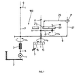
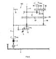
- FIG. 1 is - for reasons of clarity schematically - a first embodiment of an inventive planetary system workpiece carrier 100 shown.
- a rotary drive 1 acts between the chamber wall 3, as a mechanical reference system of the arrangement, and at least one such as a clutch 5 releasably drive-coupled to the drive 1 inventive workpiece carrier 100.
- the rotary drive is usually outside the chamber with the chamber wall 3 and arranged with a vacuum-tight rotary feedthrough carried out.
- the workpiece carrier 100 has a solar system axis 7, rotatably mounted on the mechanical reference system 3. This leads, driven, the sun's rotational movement ⁇ s .
- one or more planetary axes 11 are mounted rotatably parallel to the solar system axis 7. They are connected via a Planetenantriebsrad 13, preferably via a gear meshing, with a respect to the mechanical reference system 3 solid Mattertragerring 15 into engagement, which ring 15 is arranged coaxially to the solar system axis 7.
- At least one planetary axis 11 is at least one Planet gear 17 rotatably arranged, what, parallel to the planetary axis 11, at least one moon axis 19 is rotatably mounted.
- the planetary axis 11 is freely rotatable, this coaxial, a Mattertragerrad 21, preferably Mattertrager leopardrad, provided, which rotatably with a on the lunar axis 19 Lunar drive wheel 29, preferably designed as a gear, in Intervention is.
- a stop bracket 25 is attached, which, in its pivotal movement about the planetary axis 11, finally with a stop 27 on the solar system with sun gear 9, at P, comes in stop connection.
- the stop bracket 25 stops at the stop 27, whereupon the lunar drive wheel 29 is set in rotation.
- the lunar system rotates - ⁇ m - as long as the drive of the solar system is created, uninterrupted.
- At the lunar system is a workpiece holder for at least one in the Chamber to be treated workpiece provided.
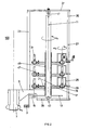
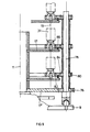
- FIG. 2 is a realization of the principle of Fig. 1 explained inventive planetary system workpiece carrier shown.
- Parts are the same reference numerals.
- the Operation of the preferred arrangement as shown in FIG. 2 According to Fig. 1 results readily from the explanations to Fig. 1.
- workpiece holders 31 are on the lunar axes 19 attached.
- the solar system is constructed as a cage, with the sun gear 9, longitudinal bars 33 and 35 and spokes 37 and 39. It can be seen that the outer longitudinal bars 35 are simultaneously, As shown in FIG. 1, 27 act as a stop.
- the planet axes 11 are, as shown at 41, stored at the top of pin bearings, what an easy removal or re-insertion of the respective Planet system with the lunar systems enabled.
- the planetary axes 11 are preferably at the bottom and as at 43 shown tapered.
- the leadership of Mattertrager leopard scholar 21 can, with a correspondingly narrow design their center opening, take place at the respective spacers 45.
- the transmitter gears 21 may be associated with three and more Moon systems through their lunar drive wheels 29 out be, which allows the center hole of the Mattertrager devis 21 material and weight saving large form, and what further results in a lower bearing friction.
- wheels 21 moon system to be guided so are preferred at the respective planetary gear 17 at least five moon systems intended.
- optionally support wheels 47 or slide supports (not shown) on the Kochtrager leopard scholarn 21 and / or planetary gears 17 may be provided to the To guide transfer wheels.
- Another design variant is the planet gears 17 rotatably connected to the spacers 45 and the latter as a bearing bushes for said transmission wheels 21st use.
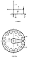
- a longitudinal bar 35 is shown and the preferred shape of the stop bracket 25 in its end.
- a U-shaped indentation 49 of the bracket 25 is pivotally mounted on the acting as a stop 27 longitudinal bar 35, which without delay at the onset of the sun's rotational movement ⁇ s and the lunar rotation ⁇ m used.
- the shape of the stop bracket 25 is the different Adapted to workpiece shapes and sizes or the lunar system design.
- planetary systems with their axes 11 be provided on the planetary systems each optionally a plurality of planet gears 17 and the latter optionally each several lunar systems, further on a drive 1 or in one Chamber according to FIG. 3 several workpiece carriers 100.
- the inventive Workpiece carrier predetermined breaking points 51 installed be done so as to minimize the damage to as small a part as possible to limit the respective batch.
- Such predetermined breaking points in the embodiment according to the Fig. 1 to 3, provided at the end portions of the stop bracket 25 be.
- the at predetermined breaking points 51 abitulden end portions of the stopper bracket 25 optically marked, e.g. be painted. It can e.g. there also optoelectronic, capacitive or inductive or magnetically detectable parts should be provided in order to operate to monitor the rotational movements in the chamber 3.
- Another way to control proper functioning the workpiece carrier according to the invention results from Measurement of the power absorbed by the drive motor 1. Will one the invention on the drive motor 1 according to FIG. 1 coupled Workpiece carrier 100 blocked, so it increases with increasing Load torque the absorbed motor power. In order to may be an alarm signal and / or an automatic shutdown to be triggered. In this way it is possible, in case of damage, to interrupt the batch processing early, the fix the detected fault and then the machining process continue where it was interrupted.
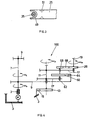
- FIG. 4 in a representation analogous to that of FIG. 1, FIG. schematically a further embodiment of an inventive Workpiece carrier 100 shown. They are the same Reference numerals as used in Fig. 1 for parts, which also in the embodiment of FIG. 4 are provided.
- Non-rotatably Mattertragerrad 66 preferably a gear
- a coaxial about the planetary axis 11 circulating Mattertragerring 68 preferably formed as internally and externally toothed ring.
- the Mattertragerrad 66 engages with the inner surface of the ring 68, with the outer surface of the lunar drive wheel 29.
- the Mattertragerring 68 is slidably mounted on the planetary gear 17.
- the lunar rotation ⁇ m can be set so slow, for example, that although the workpieces provided thereon evenly treated and treated on all sides, in particular coated, but at the same time the lunar system bearings are exposed to minimal wear.
- FIG. 5 is a realization of the schematically with reference to Fig. 4 illustrated variant of an inventive planetary system workpiece carrier shown.
- Fig. 5 is a realization of the schematically with reference to Fig. 4 illustrated variant of an inventive planetary system workpiece carrier shown.
- the transmitter surface 64 according to FIG. 4 is mounted as an internally toothed ring on retaining anchors 70, which the latter are fixed to the sun gear 9.
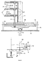
- Fig. 6 analogous to Figs. 1 and 4, again schematically, the principle of another Embodiment of the inventive workpiece carrier 100 shown.
- a circumferential Kochtrager phenomenon 72nd provided, preferably in the form of a coaxial about the planetary axis 11 circumferential (not shown in Fig. 6) internally toothed Ring.
- the lunar drive gear stands with the transmitter surface 72 in drive connection. If the moon drive 29th an externally toothed gear, it meshes with the Mattertrager composition 72 forming teeth of the coaxial about the planetary axis 11 arranged ring on the sun 9th
- FIG. 6 a preferred one is shown in FIG Embodiment of the inventive workpiece carrier variant shown in FIG. 6. It can be seen that the Transmitter surface 72, in the form of the internal toothing of a toothed ring 72a, each at the level of the orbit of the lunar drive wheels 29 are mounted by means of retaining anchors 74 on the sun gear 9.
- FIG. 8 again in analogy to the previous procedure, schematically illustrates the principle of a further embodiment of an inventive planetary system workpiece carrier. Furthermore, the same reference numbers are used for the same parts.
- transfer wheel 21, stop bracket 25 and stop 27 are eliminated.
- An auxiliary planetary gear 17 ' preferably in the form of a toothed wheel, is provided on the planet shaft 11, which engages or meshes with a transfer wheel 76, preferably in turn, a gearwheel.
- the gear ratio between solar system rotation ⁇ s and lunar system rotation ⁇ m are set.
- the Studentstragercken 80 and possibly the transfer ring 82 can be easily replaced during charging operations.
- the Studentstragercken 80 can be rotatably pushed onto the Studentstragerachse 78, wherein between each Studentstragermannn 80 each spacer sleeves are pushed over the Studentstragerachse 78.
- FIG. 9 in analogy to Figs. 2, 5 and 7, a preferred Realization form of schematically explained with reference to FIG. 8 Embodiment of the inventive workpiece carrier shown.
- Fig. 10 is a particularly simple and thus preferred Variant of the drive connection between solar system and planetary system, such as according to FIG. 1 between the sun's axis 7 and the planetary wheel 17 acting, shown.
- This arrangement can be used with all others described Arrangements for the rotary drive of the lunar systems are combined, but can also be used in systems where only a solar / planetary system is realized, i. no turning Moon system.
- the sun gear 9 is mounted on the sun axis 7, as has been explained, driven by a drive 1, not shown here, arranged outside the vacuum chamber. It carries, in turn rotatably mounted thereon, the planetary gear 17, as shown in FIG. 1 (not shown again here) and a Planetenantriebsrad 13 '.
- the sun's axis 7 runs centrally through a fixed drive wheel 88.
- a drive belt element 90 runs around the central stationary drive wheel 88 and around the provided planetary drive wheels 13 '.
- the rotational speed ⁇ p of the planet gears is freely selectable or adjustable over the diameter ratio of sun gear 9 and planetary drive wheel 13 'in a wide range.
Landscapes
- Chemical & Material Sciences (AREA)
- Chemical Kinetics & Catalysis (AREA)
- Engineering & Computer Science (AREA)
- Materials Engineering (AREA)
- Mechanical Engineering (AREA)
- Metallurgy (AREA)
- Organic Chemistry (AREA)
- Physical Vapour Deposition (AREA)
- Chemical Vapour Deposition (AREA)
- Container, Conveyance, Adherence, Positioning, Of Wafer (AREA)
Applications Claiming Priority (3)
| Application Number | Priority Date | Filing Date | Title |
|---|---|---|---|
| CH247798 | 1998-12-15 | ||
| CH247798 | 1998-12-15 | ||
| PCT/CH1999/000602 WO2000036178A1 (de) | 1998-12-15 | 1999-12-15 | Planetensystem-werkstückträger und verfahren zur oberflächenbehandlung von werkstücken |
Publications (2)
| Publication Number | Publication Date |
|---|---|
| EP1153155A1 EP1153155A1 (de) | 2001-11-14 |
| EP1153155B1 true EP1153155B1 (de) | 2005-01-19 |
Family
ID=4234683
Family Applications (1)
| Application Number | Title | Priority Date | Filing Date |
|---|---|---|---|
| EP99957242A Expired - Lifetime EP1153155B1 (de) | 1998-12-15 | 1999-12-15 | Planetensystem-werkstückträger und verfahren zur oberflächenbehandlung von werkstücken |
Country Status (5)
| Country | Link |
|---|---|
| US (1) | US6620254B2 (enExample) |
| EP (1) | EP1153155B1 (enExample) |
| JP (2) | JP4614538B2 (enExample) |
| DE (1) | DE59911507D1 (enExample) |
| WO (1) | WO2000036178A1 (enExample) |
Cited By (4)
| Publication number | Priority date | Publication date | Assignee | Title |
|---|---|---|---|---|
| CH698143B1 (de) * | 2006-01-25 | 2009-05-29 | Oerlikon Trading Ag | Werkstückträgereinrichtung. |
| US7588640B2 (en) | 2005-08-29 | 2009-09-15 | Oerlikon Trading Ag, Trubbach | Workpiece carrier device |
| WO2020225385A1 (en) | 2019-05-07 | 2020-11-12 | Oerlikon Surface Solutions Ag, Pfäffikon | Movable work piece carrier device for holding work pieces to be treated |
| US12331391B2 (en) | 2019-04-17 | 2025-06-17 | Oerlikon Surface Solutions Ag, Pfaffikon | Workpiece carrier device, method for coating a workpiece, and workpiece |
Families Citing this family (14)
| Publication number | Priority date | Publication date | Assignee | Title |
|---|---|---|---|---|
| US7081166B2 (en) * | 1999-12-15 | 2006-07-25 | Unaxis Balzers Aktiengesellschaft | Planetary system workpiece support and method for surface treatment of workpieces |
| DE50205082D1 (de) | 2001-05-08 | 2006-01-05 | Unaxis Balzers Ag | Werkstückträger |
| DE10308471B4 (de) * | 2003-02-20 | 2005-03-24 | Hensoldt Ag | Beschichtungsanlage zum Beschichten von Substraten für optische Komponenten |
| DE102004027989B4 (de) * | 2004-06-09 | 2007-05-10 | Esser, Stefan, Dr.-Ing. | Werkstückträgervorrichtung zum Halten von Werkstücken |
| CN100358098C (zh) | 2005-08-05 | 2007-12-26 | 中微半导体设备(上海)有限公司 | 半导体工艺件处理装置 |
| US7431098B2 (en) * | 2006-01-05 | 2008-10-07 | Schlumberger Technology Corporation | System and method for isolating a wellbore region |
| PL2336387T3 (pl) * | 2007-10-08 | 2014-01-31 | Oerlikon Trading Ag | Urządzenie nośne do przedmiotów obrabianych |
| US9109289B2 (en) | 2011-06-27 | 2015-08-18 | United Technologies Corporation | Manipulator for coating application |
| RU2507306C1 (ru) * | 2012-09-04 | 2014-02-20 | Открытое акционерное общество "Концерн "Центральный научно-исследовательский институт "Электроприбор" | Установка для напыления покрытий на прецизионные детали узлов гироприборов |
| DE102018126862A1 (de) | 2018-10-26 | 2020-04-30 | Oerlikon Surface Solutions Ag, Pfäffikon | Werkstückträgereinrichtung und Beschichtungsanordnung |
| JP6845877B2 (ja) * | 2019-02-14 | 2021-03-24 | Towa株式会社 | ワーク保持部回転ユニット及び真空処理装置 |
| WO2021018835A1 (en) | 2019-07-26 | 2021-02-04 | Oerlikon Surface Solutions Ag, Pfäffikon | Fixture to be used in pvd processes for cylindrical, elongated substrates |
| CN110760810B (zh) * | 2019-11-27 | 2022-04-08 | 中山凯旋真空科技股份有限公司 | 转架及具有其的镀膜设备 |
| WO2024209529A1 (ja) * | 2023-04-04 | 2024-10-10 | 京セラ株式会社 | コーティング方法 |
Family Cites Families (7)
| Publication number | Priority date | Publication date | Assignee | Title |
|---|---|---|---|---|
| US3598083A (en) * | 1969-10-27 | 1971-08-10 | Varian Associates | Complex motion mechanism for thin film coating apparatuses |
| US3853091A (en) * | 1973-12-03 | 1974-12-10 | Ibm | Thin film coating apparatus |
| US4284033A (en) * | 1979-10-31 | 1981-08-18 | Rca Corporation | Means to orbit and rotate target wafers supported on planet member |
| JPH01133320A (ja) * | 1987-11-18 | 1989-05-25 | Toshiba Mach Co Ltd | 薄膜処理装置 |
| JPH01133318A (ja) * | 1987-11-18 | 1989-05-25 | Toshiba Mach Co Ltd | 薄膜処理装置 |
| JPH01309967A (ja) * | 1988-06-07 | 1989-12-14 | Ishikawajima Harima Heavy Ind Co Ltd | スパッタリング用基板ホルダの駆動装置 |
| US5558721A (en) * | 1993-11-15 | 1996-09-24 | The Furukawa Electric Co., Ltd. | Vapor phase growth system and a gas-drive motor |
-
1999
- 1999-12-15 JP JP2000588422A patent/JP4614538B2/ja not_active Expired - Lifetime
- 1999-12-15 EP EP99957242A patent/EP1153155B1/de not_active Expired - Lifetime
- 1999-12-15 DE DE59911507T patent/DE59911507D1/de not_active Expired - Lifetime
- 1999-12-15 WO PCT/CH1999/000602 patent/WO2000036178A1/de not_active Ceased
-
2001
- 2001-06-12 US US09/879,527 patent/US6620254B2/en not_active Expired - Fee Related
-
2010
- 2010-09-01 JP JP2010195868A patent/JP5268076B2/ja not_active Expired - Fee Related
Cited By (4)
| Publication number | Priority date | Publication date | Assignee | Title |
|---|---|---|---|---|
| US7588640B2 (en) | 2005-08-29 | 2009-09-15 | Oerlikon Trading Ag, Trubbach | Workpiece carrier device |
| CH698143B1 (de) * | 2006-01-25 | 2009-05-29 | Oerlikon Trading Ag | Werkstückträgereinrichtung. |
| US12331391B2 (en) | 2019-04-17 | 2025-06-17 | Oerlikon Surface Solutions Ag, Pfaffikon | Workpiece carrier device, method for coating a workpiece, and workpiece |
| WO2020225385A1 (en) | 2019-05-07 | 2020-11-12 | Oerlikon Surface Solutions Ag, Pfäffikon | Movable work piece carrier device for holding work pieces to be treated |
Also Published As
| Publication number | Publication date |
|---|---|
| JP2002532626A (ja) | 2002-10-02 |
| JP2010265552A (ja) | 2010-11-25 |
| DE59911507D1 (de) | 2005-02-24 |
| JP5268076B2 (ja) | 2013-08-21 |
| US6620254B2 (en) | 2003-09-16 |
| JP4614538B2 (ja) | 2011-01-19 |
| US20020094383A1 (en) | 2002-07-18 |
| WO2000036178A1 (de) | 2000-06-22 |
| EP1153155A1 (de) | 2001-11-14 |
Similar Documents
| Publication | Publication Date | Title |
|---|---|---|
| EP1153155B1 (de) | Planetensystem-werkstückträger und verfahren zur oberflächenbehandlung von werkstücken | |
| AT391440B (de) | Verfahren und vorrichtung zum handhaben von gegenstaenden mittels kontinuierlich bewegter arbeitsmittel | |
| EP0355251B1 (de) | Antriebsrolleneinheit | |
| DE2558109A1 (de) | Hebevorrichtung | |
| EP3323717B1 (de) | Rotormast | |
| DE69318189T2 (de) | Fallsicherung für linearantriebe | |
| DE8112330U1 (de) | Praezisionskettenantrieb | |
| DE2602943C3 (de) | Maschine zum Herstellen von Fläschchen, Ampullen o.dgl. aus thermoplastischem Material, insbesondere Glas | |
| DE3445492A1 (de) | Bohrkopf mit planetengetriebe und einfachem bohrgestaenge | |
| DE3330337C2 (de) | Kraftdrehvorrichtung | |
| EP0870129B2 (de) | Vorrichtung zur umwandlung einer dreh- in eine axialbewegung | |
| DD157901A5 (de) | Etikettierstation einer etikettiermaschine,insbesondere fuer flaschen | |
| WO2014166512A1 (de) | Momentenlager, windkraftanlage und fahrzeug | |
| CH646626A5 (de) | Vorrichtung zum plan- und ausdrehen. | |
| DE2914364A1 (de) | Uebertragungsvorrichtung | |
| DE102004027989B4 (de) | Werkstückträgervorrichtung zum Halten von Werkstücken | |
| EP0668973B1 (de) | Umlaufrollengetriebe mit zwei eine Innenprofilierung aufweisenden Ringen und einem an der Innenseite der Ringe abrollbaren Abwälzelement | |
| DE2929445A1 (de) | Zweigang-schaltnabe fuer ein fahrrad | |
| DE3128703C2 (de) | Maschine zum Entgraten der Ränder von Blechen, Platten oder dgl. | |
| EP1749425B1 (de) | Transportvorrichtung | |
| EP0274656B1 (de) | Fangvorrichtung | |
| DE3011133C2 (de) | Vorrichtung zur Betätigung von Stromschaltern, insbesondere von Steuerstrom-Endschaltern | |
| DE885456C (de) | Fadenfortfuehrungswinde (Kaefigtrommel) | |
| EP2116312B1 (de) | Walzvorrichtung zum Schrägwalzen von rohr- oder stabförmigem Walzgut | |
| DE3212014A1 (de) | Anstellvorrichtung mit planetengetriebe |
Legal Events
| Date | Code | Title | Description |
|---|---|---|---|
| PUAI | Public reference made under article 153(3) epc to a published international application that has entered the european phase |
Free format text: ORIGINAL CODE: 0009012 |
|
| 17P | Request for examination filed |
Effective date: 20010602 |
|
| AK | Designated contracting states |
Kind code of ref document: A1 Designated state(s): AT BE CH CY DE DK ES FI FR GB GR IE IT LI LU MC NL PT SE |
|
| 17Q | First examination report despatched |
Effective date: 20011108 |
|
| RBV | Designated contracting states (corrected) |
Designated state(s): CH DE FR GB LI SE |
|
| GRAP | Despatch of communication of intention to grant a patent |
Free format text: ORIGINAL CODE: EPIDOSNIGR1 |
|
| GRAA | (expected) grant |
Free format text: ORIGINAL CODE: 0009210 |
|
| GRAS | Grant fee paid |
Free format text: ORIGINAL CODE: EPIDOSNIGR3 |
|
| AK | Designated contracting states |
Kind code of ref document: B1 Designated state(s): CH DE FR GB LI SE |
|
| REG | Reference to a national code |
Ref country code: GB Ref legal event code: FG4D Free format text: NOT ENGLISH |
|
| REG | Reference to a national code |
Ref country code: CH Ref legal event code: EP |
|
| REG | Reference to a national code |
Ref country code: IE Ref legal event code: FG4D Free format text: GERMAN |
|
| REF | Corresponds to: |
Ref document number: 59911507 Country of ref document: DE Date of ref document: 20050224 Kind code of ref document: P |
|
| GBT | Gb: translation of ep patent filed (gb section 77(6)(a)/1977) |
Effective date: 20050321 |
|
| REG | Reference to a national code |
Ref country code: SE Ref legal event code: TRGR |
|
| RAP2 | Party data changed (patent owner data changed or rights of a patent transferred) |
Owner name: UNAXIS BALZERS AKTIENGESELLSCHAFT |
|
| PLBE | No opposition filed within time limit |
Free format text: ORIGINAL CODE: 0009261 |
|
| REG | Reference to a national code |
Ref country code: FR Ref legal event code: CD |
|
| STAA | Information on the status of an ep patent application or granted ep patent |
Free format text: STATUS: NO OPPOSITION FILED WITHIN TIME LIMIT |
|
| 26N | No opposition filed |
Effective date: 20051020 |
|
| ET | Fr: translation filed | ||
| REG | Reference to a national code |
Ref country code: CH Ref legal event code: PFA Owner name: OC OERLIKON BALZERS AG Free format text: UNAXIS BALZERS AKTIENGESELLSCHAFT# #9496 BALZERS (LI) -TRANSFER TO- OC OERLIKON BALZERS AG#PATENTABTEILUNG POSTFACH 1000#9496 BALZERS (LI) |
|
| REG | Reference to a national code |
Ref country code: CH Ref legal event code: PUE Owner name: OERLIKON TRADING AG, TRUEBBACH Free format text: OC OERLIKON BALZERS AG#PATENTABTEILUNG POSTFACH 1000#9496 BALZERS (LI) -TRANSFER TO- OERLIKON TRADING AG, TRUEBBACH#HAUPTSTRASSE#9477 TRUEBBACH (CH) |
|
| REG | Reference to a national code |
Ref country code: GB Ref legal event code: 732E |
|
| REG | Reference to a national code |
Ref country code: FR Ref legal event code: CD |
|
| PGFP | Annual fee paid to national office [announced via postgrant information from national office to epo] |
Ref country code: FR Payment date: 20131209 Year of fee payment: 15 |
|
| REG | Reference to a national code |
Ref country code: FR Ref legal event code: ST Effective date: 20150831 |
|
| PG25 | Lapsed in a contracting state [announced via postgrant information from national office to epo] |
Ref country code: FR Free format text: LAPSE BECAUSE OF NON-PAYMENT OF DUE FEES Effective date: 20141231 |
|
| PGFP | Annual fee paid to national office [announced via postgrant information from national office to epo] |
Ref country code: SE Payment date: 20161223 Year of fee payment: 18 |
|
| PG25 | Lapsed in a contracting state [announced via postgrant information from national office to epo] |
Ref country code: SE Free format text: LAPSE BECAUSE OF NON-PAYMENT OF DUE FEES Effective date: 20171216 |
|
| PGFP | Annual fee paid to national office [announced via postgrant information from national office to epo] |
Ref country code: GB Payment date: 20181221 Year of fee payment: 20 Ref country code: CH Payment date: 20181227 Year of fee payment: 20 |
|
| PGFP | Annual fee paid to national office [announced via postgrant information from national office to epo] |
Ref country code: DE Payment date: 20190228 Year of fee payment: 20 |
|
| REG | Reference to a national code |
Ref country code: DE Ref legal event code: R071 Ref document number: 59911507 Country of ref document: DE |
|
| REG | Reference to a national code |
Ref country code: CH Ref legal event code: PL |
|
| REG | Reference to a national code |
Ref country code: GB Ref legal event code: PE20 Expiry date: 20191214 |
|
| PG25 | Lapsed in a contracting state [announced via postgrant information from national office to epo] |
Ref country code: GB Free format text: LAPSE BECAUSE OF EXPIRATION OF PROTECTION Effective date: 20191214 |