EP1152514A2 - Lade/entladeüberwachungsvorrichtung und -verfahren für Ableitung des Speichereffektes in einer Wiederaufladbaren Batterie - Google Patents
Lade/entladeüberwachungsvorrichtung und -verfahren für Ableitung des Speichereffektes in einer Wiederaufladbaren Batterie Download PDFInfo
- Publication number
- EP1152514A2 EP1152514A2 EP01110382A EP01110382A EP1152514A2 EP 1152514 A2 EP1152514 A2 EP 1152514A2 EP 01110382 A EP01110382 A EP 01110382A EP 01110382 A EP01110382 A EP 01110382A EP 1152514 A2 EP1152514 A2 EP 1152514A2
- Authority
- EP
- European Patent Office
- Prior art keywords
- voltage
- charging
- discharging
- secondary battery
- charge
- Prior art date
- Legal status (The legal status is an assumption and is not a legal conclusion. Google has not performed a legal analysis and makes no representation as to the accuracy of the status listed.)
- Withdrawn
Links
Images


Classifications
-
- B—PERFORMING OPERATIONS; TRANSPORTING
- B60—VEHICLES IN GENERAL
- B60W—CONJOINT CONTROL OF VEHICLE SUB-UNITS OF DIFFERENT TYPE OR DIFFERENT FUNCTION; CONTROL SYSTEMS SPECIALLY ADAPTED FOR HYBRID VEHICLES; ROAD VEHICLE DRIVE CONTROL SYSTEMS FOR PURPOSES NOT RELATED TO THE CONTROL OF A PARTICULAR SUB-UNIT
- B60W10/00—Conjoint control of vehicle sub-units of different type or different function
- B60W10/24—Conjoint control of vehicle sub-units of different type or different function including control of energy storage means
- B60W10/26—Conjoint control of vehicle sub-units of different type or different function including control of energy storage means for electrical energy, e.g. batteries or capacitors
-
- H—ELECTRICITY
- H02—GENERATION; CONVERSION OR DISTRIBUTION OF ELECTRIC POWER
- H02J—CIRCUIT ARRANGEMENTS OR SYSTEMS FOR SUPPLYING OR DISTRIBUTING ELECTRIC POWER; SYSTEMS FOR STORING ELECTRIC ENERGY
- H02J7/00—Circuit arrangements for charging or depolarising batteries or for supplying loads from batteries
- H02J7/0069—Charging or discharging for charge maintenance, battery initiation or rejuvenation
-
- Y—GENERAL TAGGING OF NEW TECHNOLOGICAL DEVELOPMENTS; GENERAL TAGGING OF CROSS-SECTIONAL TECHNOLOGIES SPANNING OVER SEVERAL SECTIONS OF THE IPC; TECHNICAL SUBJECTS COVERED BY FORMER USPC CROSS-REFERENCE ART COLLECTIONS [XRACs] AND DIGESTS
- Y10—TECHNICAL SUBJECTS COVERED BY FORMER USPC
- Y10S—TECHNICAL SUBJECTS COVERED BY FORMER USPC CROSS-REFERENCE ART COLLECTIONS [XRACs] AND DIGESTS
- Y10S903/00—Hybrid electric vehicles, HEVS
- Y10S903/902—Prime movers comprising electrical and internal combustion motors
- Y10S903/903—Prime movers comprising electrical and internal combustion motors having energy storing means, e.g. battery, capacitor
Definitions
- the present invention relates generally to a technique of canceling memory effects in secondary batteries, particularly to a technique of canceling memory effects in secondary batteries used for applications in which the secondary batteries are charged and discharged repeatedly in a charged but not fully charged state and it is difficult to discharge the secondary batteries completely.
- the secondary battery examples include lead batteries, nickelcadmium (Ni-Cd) batteries, nickel metal-hydride (Ni-MH) batteries, and lithium ion batteries.
- Such batteries have a characteristic allowing them to be connected to an external power source to be charged with a predetermined current supplied from the power source after consumption of their electric power.
- These batteries have been used for various equipment, making good use of such a characteristic.
- such a battery may be mounted on a vehicle to supply electric power to an ignition plug of its engine.
- a battery also is used as a main power source for driving an electric motor in a pure electric vehicle (PEV) or a so-called hybrid electric vehicle (HEV) provided with an engine and an electric motor.
- PEV pure electric vehicle
- HEV hybrid electric vehicle
- the secondary battery may be charged and discharged repeatedly while the HEV is driven.
- the HEV when the output of its engine is higher than the required power for driving, a generator is driven with the surplus power to charge the secondary battery.
- an electric motor is driven with the electric power of the secondary battery to output power sufficient to cover the shortage of the required power.
- the secondary battery is discharged.
- Such repeated charge and discharge are carried out according to the driving state of the vehicle, the charged state of the battery, and an operation of a driver.
- the memory effect can be cancelled when the battery is forced to be discharged until the voltage per cell drops to 1V.
- a number of cells are connected in series to form a battery assembly in order to obtain the required output for driving an electric motor, and a battery voltage, current, and temperature are monitored so that the charge and discharge are repeated with the state of charge (SOC) of the secondary battery being in a range of 30% to 75% of a fully charged state.
- SOC state of charge
- a first charging/discharging control device includes a secondary battery, a memory effect determinator, and a discharging controller.
- the secondary battery is formed of a battery assembly with a plurality of cells combined with one another.
- the memory effect determinator determines whether a discharging memory effect has occurred, based on at least one of the following determinations: whether a time of charging/discharging of the secondary battery has reached a predetermined time; whether a charging/discharging amount in the secondary battery has reached a predetermined amount; and whether a voltage per cell has reached a voltage V1 at a lower-limit state of charge in a range of capacity actually used.
- the discharging controller discharges the secondary battery until the voltage per cell reaches a voltage V3 that is higher than 1.0 V and is lower than the voltage V1 at the lower-limit state of charge when the memory effect determinator determines that the discharging memory effect has occurred.
- a second charging/discharging control device includes a secondary battery, a memory effect determinator, and a discharging controller.
- the secondary battery is formed of a battery assembly with a plurality of cells combined with one another.
- the memory effect determinator determines whether a discharging memory effect has occurred, based on at least one of the following determinations: whether a time of charging/discharging of the secondary battery has reached a predetermined time; whether a charging/discharging amount in the secondary battery has reached a predetermined amount; and whether a voltage per cell has reached a voltage V1 at a lower-limit state of charge in a range of capacity actually used.
- the discharging controller discharges the secondary battery for a predetermined amount from the lower-limit state of charge when the memory effect determinator determines that the discharging memory effect has occurred.
- the first and second charging/discharging control devices further include a charging controller for charging the secondary battery until the voltage per cell reaches a voltage V4 that is higher than a voltage V2 at an upper-limit state of charge in the range of capacity actually used after completion of the discharging of the secondary battery by the discharging controller based on the determination by the memory effect determinator that the discharging memory effect has occurred.
- a charging controller for charging the secondary battery until the voltage per cell reaches a voltage V4 that is higher than a voltage V2 at an upper-limit state of charge in the range of capacity actually used after completion of the discharging of the secondary battery by the discharging controller based on the determination by the memory effect determinator that the discharging memory effect has occurred.
- discharging and charging of the secondary battery are repeated in this order at least once, wherein the discharging is carried out by the discharging controller until the voltage per cell reaches the voltage V3, which is lower than the voltage V1 at the lower-limit state of charge, from the voltage V4, which is higher than the voltage V2 at the upper-limit state of charge, and the charging is carried out by the charging controller until the voltage per cell reaches the voltage V4, which is higher than the voltage V2 at the upper-limit state of charge, from the voltage V3, which is lower than the voltage V1 at the lower-limit state of charge.
- the first charging/discharging control device further includes a charging level corrector for correcting a charging level at the lower-limit state of charge based on a discharging amount when discharging is carried out until the voltage per cell reaches the voltage V3, which is lower than the voltage V1 at the lower-limit state of charge, from the voltage V1 by the discharging controller.
- a charging level corrector for correcting a charging level at the lower-limit state of charge based on a discharging amount when discharging is carried out until the voltage per cell reaches the voltage V3, which is lower than the voltage V1 at the lower-limit state of charge, from the voltage V1 by the discharging controller.
- the second charging/discharging control device further includes a charging level corrector for correcting a charging level at the lower-limit state of charge based on the voltage per cell after the secondary battery is discharged for the predetermined amount from the lower-limit state of charge by the discharging controller.
- a charging level corrector for correcting a charging level at the lower-limit state of charge based on the voltage per cell after the secondary battery is discharged for the predetermined amount from the lower-limit state of charge by the discharging controller.
- a third charging/discharging control device includes a secondary battery, a memory effect determinator, and a charging controller.
- the secondary battery is formed of a battery assembly with a plurality of cells combined with one another.
- the memory effect determinator determines whether a charging memory effect has occurred, based on at least one of the following determinations: whether a time of charging/discharging of the secondary battery has reached a predetermined time; whether a charging/discharging amount in the secondary battery has reached a predetermined amount; and whether a voltage per cell has reached a voltage V2 at an upper-limit state of charge in a range of capacity actually used.
- the charging controller charges the secondary battery until the voltage per cell reaches a voltage V4 that is higher than the voltage V2 at the upper-limit state of charge when the memory effect determinator determines that the charging memory effect has occurred.
- a fourth charging/discharging control device includes a secondary battery, a memory effect determinator, and a charging controller.
- the secondary battery is formed of a battery assembly with a plurality of cells combined with one another.
- the memory effect determinator determines whether a charging memory effect has occurred, based on at least one of the following determinations: whether a time of charging/discharging of the secondary battery has reached a predetermined time; whether a charging/discharging amount in the secondary battery has reached a predetermined amount; and whether a voltage per cell has reached a voltage V2 at an upper-limit state of charge in a range of capacity actually used.
- the charging controller charges the secondary battery for a predetermined amount from the upper-limit state of charge when the memory effect determinator determines that the charging memory effect has occurred.
- the third and fourth charging/discharging control devices further include a discharging controller for discharging the secondary battery until the voltage per cell reaches a voltage V3 that is lower than a voltage V1 at a lower-limit state of charge in the range of capacity actually used after completion of the charging of the secondary battery by the charging controller based on the determination by the memory effect determinator that the charging memory effect has occurred.
- a discharging controller for discharging the secondary battery until the voltage per cell reaches a voltage V3 that is lower than a voltage V1 at a lower-limit state of charge in the range of capacity actually used after completion of the charging of the secondary battery by the charging controller based on the determination by the memory effect determinator that the charging memory effect has occurred.
- charging and discharging of the secondary battery are repeated in this order at least once, wherein the charging is carried out by the charging controller until the voltage per cell reaches the voltage V4, which is higher than the voltage V2 at the upper-limit state of charge, from the voltage V3, which is lower than the voltage V1 at the lower-limit state of charge, and the discharging is carried out by the discharging controller until the voltage per cell reaches the voltage V3, which is lower than the voltage V1 at the lower-limit state of charge, from the voltage V4, which is higher than the voltage V2 at the upper-limit state of charge.
- a first charging/discharging control method includes: determining whether a discharging memory effect has occurred, based on at least one of the following determinations: whether a time of charging/discharging of a secondary battery formed of a battery assembly with a plurality of cells combined with one another has reached a predetermined time; whether a charging/discharging amount in the secondary battery has reached a predetermined amount; and whether a voltage per cell has reached a voltage V1 at a lower-limit state of charge in a range of capacity actually used; and discharging the secondary battery until the voltage per cell reaches a voltage V3 that is higher than 1.0 V and is lower than the voltage V1 at the lower-limit state of charge when it is determined that the discharging memory effect has occurred.
- a second charging/discharging control method includes determining whether a discharging memory effect has occurred, based on at least one of the following determinations: whether a time of charging/discharging of a secondary battery formed of a battery assembly with a plurality of cells combined with one another has reached a predetermined time; whether a charging/discharging amount in the secondary battery has reached a predetermined amount; and whether a voltage per cell has reached a voltage V1 at a lower-limit state of charge in a range of capacity actually used; and discharging the secondary battery for a predetermined amount from the lower-limit state of charge when it is determined that the discharging memory effect has occurred.
- the first and second charging/discharging control methods further include charging the secondary battery until the voltage per cell reaches a voltage V4 that is higher than a voltage V2 at an upper-limit state of charge in the range of capacity actually used after completion of the discharging of the secondary battery based on the determination that the discharging memory effect has occurred.
- discharging and charging of the secondary battery are repeated in this order at least once, wherein the discharging is carried out until the voltage per cell reaches the voltage V3, which is lower than the voltage V1 at the lower-limit state of charge, from the voltage V4, which is higher than the voltage V2 at the upper-limit state of charge, and the charging is carried out until the voltage per cell reaches the voltage V4, which is higher than the voltage V2 at the upper-limit state of charge, from the voltage V3, which is lower than the voltage V1 at the lower-limit state of charge.
- the first charging/discharging control method further includes correcting a charging level at the lower-limit state of charge based on a discharging amount when the discharging is carried out until the voltage per cell reaches the voltage V3, which is lower than the voltage V1 at the lower-limit state of charge, from the voltage V1.
- the second charging/discharging control method further includes correcting a charging level at the lower-limit state of charge based on the voltage per cell after the secondary battery is discharged for the predetermined amount from the lower-limit state of charge.
- a third charging/discharging control method includes determining whether a charging memory effect has occurred, based on at least one of the following determinations: whether a time of charging/discharging of a secondary battery formed of a battery assembly with a plurality of cells combined with one another has reached a predetermined time; whether a charging/discharging amount in the second battery has reached a predetermined amount; and whether a voltage per cell has reached a voltage V2 at an upper-limit state of charge in a range of capacity actually used; and charging the secondary battery until the voltage per cell reaches a voltage V4 that is higher than the voltage V2 at the upper-limit state of charge when it is determined that the charging memory effect has occurred.
- a fourth charging/discharging control method includes: determining whether a charging memory effect has occurred, based on at least one of the following determinations: whether a time of charging/discharging of a secondary battery formed of a battery assembly with a plurality of cells combined with one another has reached a predetermined time; whether a charging/discharging amount in the secondary battery has reached a predetermined amount; and whether a voltage per cell has reached a voltage V2 at an upper-limit state of charge in a range of capacity actually used; and charging the secondary battery for a predetermined amount from the upper-limit state of charge when it is determined that the charging memory effect has occurred.
- the third and fourth charging/discharging control methods further include discharging the secondary battery until the voltage per cell reaches a voltage V3 that is lower than a voltage V1 at a lower-limit state of charge in the range of capacity actually used after completion of the charging of the secondary battery based on the determination that the charging memory effect has occurred.
- charging and discharging of the secondary battery are repeated in this order at least once, wherein the charging is carried out until the voltage per cell reaches the voltage V4, which is higher than the voltage V2 at the upper-limit state of charge, from the voltage V3, which is lower than the voltage V1 at the lower-limit state of charge, and the discharging is carried out until the voltage per cell reaches the voltage V3, which is lower than the voltage V1 at the lower-limit state of charge, from the voltage V4, which is higher than the voltage V2 at the upper-limit state of charge.
- the memory effect caused during discharging is detected based on the charging/discharging time, charging/discharging amount, and voltage drop to the voltage corresponding to the lower-limit state of charge of the secondary battery during driving of the vehicle. Then, the battery is discharged to reach a lower state of charge than a lower-limit state of charge in the range of capacity actually used and thus the discharging memory effect in the range of capacity actually used is cancelled. In addition, the charging level at the lower-limit state of charge is corrected, so that the state of charge is controlled accurately. Afterward, the secondary battery is charged to reach a higher state of charge than the upper-limit state of charge, so that the charging memory effect also can be cancelled.
- the memory effect caused during charging is detected based on the charging/discharging time, charging/discharging amount, and voltage rise to the voltage corresponding to the upper-limit state of charge in the range of capacity actually used of the secondary battery.
- the battery is charged to reach a higher state of charge than the upper-limit state of charge, so that the charging memory effect in the range of capacity actually used is cancelled.
- the battery is discharged to reach a lower state of charge than the lower-limit state of charge, so that the discharging memory effect also can be cancelled.
- FIG. 1 is a block diagram showing a configuration of a charging/discharging control device according to a first embodiment of the present invention.
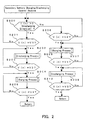
- FIG. 2 is a flowchart showing a secondary-battery charging/discharging control routine according to the first embodiment of the present invention.
- FIG. 3 is a graph showing a curve indicating a battery voltage with respect to a state of charge SOC, for explaining a method of canceling a memory effect caused during discharging according to the first embodiment.
- FIG. 4 is a graph showing a curve indicating a battery voltage with respect to a state of charge SOC, for explaining a method of canceling a memory effect caused during charging according to the first embodiment.
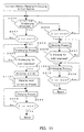
- FIG. 5 is a flowchart showing a secondary-battery charging/discharging control routine according to a second embodiment of the present invention.
- FIG. 6 is a graph showing a curve indicating a battery voltage with respect to a state of charge SOC, for explaining a charging level correction during discharging of a secondary battery according to the second embodiment.
- FIG. 7 is a graph showing a curve indicating a correction amount ⁇ with respect to a measured variation ⁇ SOC(B) from a lower-limit state of charge SOCa1, for explaining the charging level correction during discharging of a secondary battery according to the second embodiment.
- FIG. 8 is a flowchart showing a secondary-battery charging/discharging control routine according to a third embodiment of the present invention.
- FIG. 9 is a graph showing a curve indicating a battery voltage with respect to a state of charge SOC, for explaining a method of canceling a memory effect caused during discharging according to the third embodiment.
- FIG. 10 is a graph showing a curve indicating a battery voltage with respect to a state of charge SOC, for explaining a method of canceling a memory effect caused during charging according to the third embodiment.
- FIG. 11 is a flowchart showing a secondary-battery charging/discharging control routine according to a fourth embodiment of the present invention.
- FIG. 12 is a graph showing a curve indicating a battery voltage with respect to a state of charge SOC, for explaining a charging level correction during discharging of a secondary battery according to the fourth embodiment.
- FIG. 1 is a block diagram showing a configuration of a charging/discharging control device according to a first embodiment of the present invention.
- numeral 1 indicates a secondary battery formed of, for example, a nickel metal-hydride battery to be loaded on a hybrid electric vehicle or the like.
- this secondary battery 1 includes a battery pack formed of a battery assembly with a number of cells combined with one another to obtain a predetermined output power for an electric motor.
- Numeral 2 is a current detector disposed between a minus output terminal of the secondary battery 1 and a minus input terminal (-) of the electric motor (not shown in the figure).
- the current detector samples a charging/discharge current of the secondary battery 1 output from a current sensor (not shown in the figure) per predetermined time to obtain a current sample I(n) and thus detects the magnitude of the current.
- the current detector also detects that the current is a charge or discharge (C/D) current based on the sign of the current sample I(n). In the present embodiment, the case where the sign of the current sample I(n) is positive is set to indicate discharge.
- Numeral 4 indicates a temperature detector.
- the temperature detector 4 samples a battery temperature output from a temperature sensor (not shown in the figure) disposed in a predetermined position inside the secondary battery 1 per predetermined time to obtain a temperature sample T(n).
- Numeral 6 is a voltage detector.
- the voltage detector 6 samples an output voltage from the secondary battery 1 per predetermined time to obtain a voltage sample V(n) at least per cell.
- the current sample I(n) from the current detector 2, the temperature sample T(n) from the temperature detector 4, and the voltage sample V(n) from the voltage detector 6 are sent to a state-of-charge (SOC) operator 16.
- SOC state-of-charge
- the current sample I(n) and charging or discharging direction obtained by the current detector 2, the charging/discharging amount and state of charge determined in the state-of-charge operator 16, and the voltage sample V(n) obtained by the voltage detector 6 are sent to a memory effect determinator 14.
- the memory effect determinator 14 determines whether a memory effect has occurred during discharging or charging, based on one or more of the following determinations: whether the charging/discharging time has reached a predetermined time; whether the charging/discharging amount has reached a predetermined amount according to driving of the vehicle; or whether the voltage per cell has reached a voltage V1 (for instance, about 1.2 V per cell) at a lower-limit state of charge SOCa1 (for example, 30% of the fully charged state) in a range of capacity actually used during the discharging; and whether the voltage per cell has reached a voltage V2 (for instance, about 1.4V per cell) at an upper-limit state of charge SOCb1 (for example, 75% of the fully charged state) in a range of capacity actually used during the charging.
- V1 for instance, about 1.2 V per cell
- SOCa1 for example, 30% of the fully charged state
- V2 for instance, about 1.4V per cell
- Numeral 8 indicates a discharging controller.
- the discharging controller 8 cancels the memory effect caused during the discharging by further discharging the secondary battery 1 based on the discharging control signal from the memory effect determinator 14 when the memory effect determinator 14 determines that the memory effect has occurred during the discharging.
- Numeral 10 indicates a charging controller.
- the charging controller 10 cancels the memory effect caused during the charging by further charging the secondary battery 1 with regenerative electric power from a generator 12 based on the charging control signal from the memory effect determinator 14 when the memory effect determinator 14 determines that the memory effect has occurred during the charging.
- Numeral 18 indicates a charging level corrector.
- the charging level corrector 18 calculates a correction amount for correcting the charging level of the secondary battery 1 when the state of charge reaching the voltage V1 deviates from 30% as the lower-limit state of charge due to the distance driven by the vehicle or the like in canceling the memory effect caused during the discharging.
- FIG. 2 is a flowchart showing a secondary battery charging/discharging control routine according to the first embodiment of the present invention.
- FIGs. 3 and 4 are graphs obtained by plotting battery voltages with respect to the state of charge, for explaining the methods of canceling the memory effects caused during discharging and charging according to the first embodiment, respectively.
- step 200 it is determined whether the sign of the current sample I(n) indicates the discharging direction (i.e. whether the sign is positive) (S200).
- step 200 it is determined whether the sign of the current sample I(n) indicates the discharging direction (i.e. whether the sign is positive) (S200).
- step 200 it is determined whether the voltage sample V(n) at least per cell of the secondary battery has dropped to the voltage V1 (about 1.2 V per cell) at the lower-limit state of charge SOCa1 (about 30% of the fully charged state) of the secondary battery used during driving of the vehicle (S201).
- the determination that the voltage sample V(n) at least per cell had not dropped to the voltage V1 was made at step 201, it is determined that the memory effect has not occurred during discharging and thus the procedure is returned to step 200 (i.e. following a discharge curve D1 in the ordinary case shown in FIG. 3).
- step 201 When the determination that the voltage sample V(n) at least per cell had reached the voltage V1 was made at step 201 (the curve D1 shifts to the curve D2 shown in FIG. 3), it is determined that the memory effect has occurred during the discharging and a discharging process is carried out further to discharge the secondary battery (S202). Next, it is determined whether the voltage sample V(n) at least per cell has dropped to the voltage V3 (about 1.1 V per cell) as the result of the discharging process at step 202 (S203). When it is determined at step 203 that the voltage sample V(n) has not dropped to the voltage V3, the discharging process at step 202 continues (i.e. following a discharge curve D3 shown in FIG. 3).
- step 203 When it was determined at step 203 that the voltage sample V(n) at least per cell had dropped to the voltage V3, the procedure is advanced to step 204 and a charging process is carried out to prevent the occurrence of the memory effect during charging.
- step 205 it is determined whether the voltage sample V(n) at least per cell has risen to the voltage V4 (for instance, about 1.5 V per cell) exceeding the voltage V2 (about 1.4 V per cell) at the upper-limit state of charge used during driving of the vehicle by the charging process at step 204 (S205).
- the charging process at step 204 continues (i.e. following the charging curve C4 shown in FIG. 3).
- step 200 When it is determined at step 200 described above that the sign of the current sample I(n) indicates the charging direction, the procedure is advanced to step 206 and it is determined whether the voltage sample V(n) at least per cell of the secondary battery has risen to the voltage V2 (about 1.4 V per cell) at the upper-limit state of charge SOCb1 (about 75% of the fully charged state) of the secondary battery used during driving of the vehicle.
- the determination that the voltage sample V(n) at least per cell had not risen to the voltage V2 was made at step 206, it is determined that the memory effect has not occurred during the charging and the procedure is returned to step 200 (i.e. following the charging curve C1 in an ordinary case shown in FIG. 4).
- step 206 When the determination that the voltage sample V(n) at least per cell had reached the voltage V2 was made at step 206 (the curve C1 shifts to the curve C2 shown in FIG. 4), it is determined that the memory effect has occurred during the charging and thus a charging process is carried out further to charge the secondary battery (S207). Next, it is determined whether the voltage sample V(n) at least per cell has risen to the voltage V4 (about 1.5 V per cell) as the result of the charging process at step 207 (S208). When it is determined at step 208 that the voltage sample V(n) has not risen to the voltage V4, the charging process at step 207 continues (i.e. following the charging curve C3 shown in FIG. 4).
- step 208 When it was determined at step 208 that the voltage sample V(n) at least per cell had risen to the voltage V4, the procedure is advanced to step 209 and the discharging process is carried out to prevent the occurrence of the memory effect during discharging.
- step 210 it is determined whether the voltage sample V(n) at least per sample has dropped to the voltage V3 (about 1.1 V per cell) below the voltage V1 (about 1.2 V per cell) at the lower-limit state of charge by the discharging process at step 209 (S210).
- the discharging process at step 209 continues (i.e. following the discharging curve D4 shown in FIG. 4).
- step 210 When it was determined at step 210 that the voltage sample V(n) had dropped to the voltage V3, the secondary battery charging/discharging control routine in the charging direction is ended.
- FIG. 5 is a flowchart showing a secondary battery charging/discharging control routine according to the second embodiment of the present invention.
- the present embodiment is different from the first embodiment in that in addition to the cancellation of the memory effects during discharging and charging, a charging level of the secondary battery is corrected and thus the range of capacity actually used is controlled accurately when the state of charge reaching the voltage V1 deviates from the lower-limit state of charge SOCa1 (about 30% of the fully charged state) due to the distance the vehicle was driven or the like.
- SOCa1 about 30% of the fully charged state
- FIGs. 6 and 7 are a graph showing a curve indicating a battery voltage with respect to the state of charge SOC and a graph showing a curve indicating a correction amount ⁇ with respect to the measured variation ⁇ SOC(B) from the lower-limit state of charge SOCa1, respectively, for explaining the charging level correction in discharging of the secondary battery according to the second embodiment.
- step 203 when it was determined at step 203 that the voltage sample V(n) at least per cell had dropped to the voltage V3, the memory effect caused during discharging has been cancelled.
- step 500 the procedure is advanced to step 500, and when the state of charge reaching the voltage V1 deviates from the lower-limit state of charge SOCa1 (about 30% of the fully charged state) during driving of the vehicle, the variation ⁇ SOC(B) is obtained.
- FIG. 6 shows a curve D60 experimentally obtained and curves D61 and D62 in the cases of deviations to the lower and higher levels from the lower-limit state of charge SOCa1, respectively.
- a charging level correction process is carried out.
- This process is carried out as follows. That is, an actual measurement value of the variation ⁇ SOC(B) from the lower-limit state of charge SOCa1 obtained at step 500 is compared with an experimental value of the variation ⁇ SOC(A) during the drop from the voltage V1 to the voltage V3 experimentally pre-determined; the difference (a correction amount ⁇ ) between the experimental value of the variation ⁇ SOC(A) and the actual measurement value of the variation ⁇ SOC(B) is calculated; and the correction amount ⁇ is added to the lower-limit state of charge SOCal ( ⁇ D61 and ⁇ D62 are added to the curves D61 and D62 shown in FIG. 6).
- FIG. 7 shows a curve indicating the correction amount ⁇ using the voltage V SOCa1 at the time of passing the lower-limit state of charge SOCa1 as a parameter.
- V SOCa1 V1
- V SOCa1 V1
- V SOCa1 V1
- the occurrence of the memory effect is determined based on the voltage drop in the secondary battery.
- V SOCa1 > V1 and V SOCa1 ⁇ V1 the occurrence of the memory effect is determined based on the distance the vehicle was driven, the number of times for which the state of charge has reached the lower- or upper-limit in the range of capacity actually used of the secondary battery, and the like in addition to the voltage drop in the secondary battery.
- FIG. 8 is a flowchart showing a secondary battery charging/discharging control routine according to the third embodiment of the present invention.
- the discharging was allowed to continue for a period in which the battery voltage drops from the voltage V1 to the voltage V3 and the charging was allowed to continue for a period in which the battery voltage rises from the voltage V2 to the voltage V4.
- the present embodiment is different from the first embodiment in that discharging is carried out for a predetermined discharging amount ⁇ Ah1 after the battery voltage reaches the voltage V1 and charging is carried out for a predetermined charging amount ⁇ Ah2 after the battery voltage reaches the voltage V2.
- ⁇ Ah1 after the battery voltage reaches the voltage V1
- charging is carried out for a predetermined charging amount ⁇ Ah2 after the battery voltage reaches the voltage V2.
- FIGs. 9 and 10 are graphs obtained by plotting the battery voltages with respect to the state of charge SOC, for explaining the method of canceling the memory effects caused during discharging and charging according to the third embodiment.
- step 808 When it is determined at step 808 that the charging has been carried out for the predetermined charging amount ⁇ Ah2, the canceling of the memory effect caused during the charging is completed.
- FIG. 11 is a flowchart showing a secondary battery charging/discharging control routine according to the fourth embodiment of the present invention.
- the present embodiment is different from the third embodiment in that in addition to the cancellation of the memory effects during discharging and charging, the charging level of the secondary battery is corrected and thus the range of capacity actually used is controlled accurately in the case where an actual voltage drop ⁇ V(B) deviates from a voltage drop ⁇ V(A) experimentally obtained when the discharging is carried out for ⁇ Ah1 at the battery voltage V1, due to the distance the vehicle was driven or the like.
- the same steps as in the third embodiment are indicated with the same numerals and characters and their descriptions are not repeated.
- FIG. 12 is a graph showing a curve indicating a battery voltage with respect to the state of charge (SOC), for explaining charging level correction during discharging of a secondary battery according to the fourth embodiment.
- SOC state of charge
- FIG. 12 shows a curve D120 (a voltage-drop experimental value ⁇ V(A)) experimentally obtained and a curve D121 in the case where the voltage-drop actual measurement value ⁇ V(B) deviates from the voltage-drop experimental value ⁇ V(A).
- a charging level correction process is carried out as follows.
- the voltage-drop actual measurement value ⁇ V(B) obtained at step 1100 is compared with the voltage-drop experimental value ⁇ V(A) experimentally pre-determined; the difference (a correction amount ⁇ ) between the voltage-drop experimental value ⁇ V(A) and the voltage-drop actual measurement value ⁇ V(B) is calculated; and the correction amount ⁇ is added to the lower-limit state of charge SOCa1.
- a device and a method are provided in which memory effects can be cancelled by controlling charging and discharging of a secondary battery during driving of a vehicle.
- a memory effect determinator determines that the discharging memory effect has occurred, based on at least one of the following determinations: whether a time of charging/discharging of a secondary battery has reached a predetermined time; whether a charging/discharging amount in the secondary battery has reached a predetermined amount; and whether a voltage per cell has reached a voltage V1 at a lower-limit state of charge in a range of capacity actually used, a discharging controller discharges the secondary battery until the voltage per cell reaches a voltage V3 that is higher than 1.0 V and is lower than the voltage V1 at the lower-limit state of charge.
Landscapes
- Engineering & Computer Science (AREA)
- Power Engineering (AREA)
- Chemical & Material Sciences (AREA)
- Combustion & Propulsion (AREA)
- Transportation (AREA)
- Mechanical Engineering (AREA)
- Charge And Discharge Circuits For Batteries Or The Like (AREA)
- Electric Propulsion And Braking For Vehicles (AREA)
- Hybrid Electric Vehicles (AREA)
- Secondary Cells (AREA)
Applications Claiming Priority (2)
| Application Number | Priority Date | Filing Date | Title |
|---|---|---|---|
| JP2000131756 | 2000-04-28 | ||
| JP2000131756A JP4138204B2 (ja) | 2000-04-28 | 2000-04-28 | 充放電制御装置および方法 |
Publications (2)
| Publication Number | Publication Date |
|---|---|
| EP1152514A2 true EP1152514A2 (de) | 2001-11-07 |
| EP1152514A3 EP1152514A3 (de) | 2005-06-15 |
Family
ID=18640591
Family Applications (1)
| Application Number | Title | Priority Date | Filing Date |
|---|---|---|---|
| EP01110382A Withdrawn EP1152514A3 (de) | 2000-04-28 | 2001-04-26 | Lade/entladeüberwachungsvorrichtung und -verfahren für Ableitung des Speichereffektes in einer Wiederaufladbaren Batterie |
Country Status (3)
| Country | Link |
|---|---|
| US (1) | US6465988B2 (de) |
| EP (1) | EP1152514A3 (de) |
| JP (1) | JP4138204B2 (de) |
Cited By (1)
| Publication number | Priority date | Publication date | Assignee | Title |
|---|---|---|---|---|
| CN102844962A (zh) * | 2011-01-06 | 2012-12-26 | 松下电器产业株式会社 | 碱性蓄电池的充放电控制方法以及电源系统 |
Families Citing this family (14)
| Publication number | Priority date | Publication date | Assignee | Title |
|---|---|---|---|---|
| JP4118035B2 (ja) * | 2001-08-03 | 2008-07-16 | トヨタ自動車株式会社 | 電池制御装置 |
| KR20030029217A (ko) * | 2001-10-05 | 2003-04-14 | 삼성전자주식회사 | 배터리충전장치 및 충전방법 |
| JP2003259508A (ja) * | 2002-02-26 | 2003-09-12 | Sanyo Electric Co Ltd | 電気自動車用の電源装置 |
| JP4038456B2 (ja) | 2003-08-25 | 2008-01-23 | 株式会社豊田中央研究所 | 電池特性検出方法 |
| KR100692404B1 (ko) | 2004-12-21 | 2007-03-09 | 현대자동차주식회사 | 메모리효과를 방지하기 위한 배터리 충전상태 계산 알고리즘 |
| KR100736995B1 (ko) * | 2005-11-18 | 2007-07-09 | 현대자동차주식회사 | 하이브리드차량의 배터리 노후화 계수 산출 방법 |
| JP4271682B2 (ja) * | 2005-11-24 | 2009-06-03 | 本田技研工業株式会社 | モータ駆動車両の制御装置 |
| EP2069658A1 (de) * | 2006-09-12 | 2009-06-17 | Purdue Research Foundation | Getriebe mit geteilter leistung und energiewiederherstellung |
| JP5137603B2 (ja) * | 2008-01-31 | 2013-02-06 | パナソニック株式会社 | アルカリ蓄電池の充放電制御方法および充放電制御システム |
| JP5051794B2 (ja) * | 2009-12-17 | 2012-10-17 | トヨタ自動車株式会社 | 充電装置 |
| JP5586348B2 (ja) * | 2010-07-02 | 2014-09-10 | ラピスセミコンダクタ株式会社 | 充電装置、充電制御装置、電圧監視装置、ad変換装置、基準電圧回路の自己診断方法 |
| JP5462096B2 (ja) * | 2010-07-15 | 2014-04-02 | 株式会社マキタ | 電動工具用バッテリ |
| JP6003091B2 (ja) * | 2012-02-29 | 2016-10-05 | オムロン株式会社 | 電圧監視装置および電圧監視方法 |
| JP6107349B2 (ja) * | 2013-04-11 | 2017-04-05 | スズキ株式会社 | バッテリ充放電制御装置 |
Citations (2)
| Publication number | Priority date | Publication date | Assignee | Title |
|---|---|---|---|---|
| US4302714A (en) * | 1979-04-27 | 1981-11-24 | Yefsky Sheldon A | Rechargeable battery charger system for charging testing, rejuvenation and preventative maintenance |
| US5475294A (en) * | 1991-12-27 | 1995-12-12 | Nippon Densan Corporation | Charge controller for battery charger |
Family Cites Families (6)
| Publication number | Priority date | Publication date | Assignee | Title |
|---|---|---|---|---|
| US5355072A (en) * | 1991-07-31 | 1994-10-11 | Sanyo Electric Co., Ltd. | Battery discharging apparatus |
| JP3316277B2 (ja) | 1993-10-27 | 2002-08-19 | 三洋電機株式会社 | 二次電池のメモリー効果解消方法 |
| JP3225771B2 (ja) * | 1995-01-27 | 2001-11-05 | トヨタ自動車株式会社 | 電気自動車用バッテリ放電装置 |
| TW318289B (de) * | 1996-01-26 | 1997-10-21 | Yamaha Motor Co Ltd | |
| JP4121098B2 (ja) * | 1997-09-30 | 2008-07-16 | 松下電器産業株式会社 | 水酸化ニッケル正極を用いた二次電池の残存容量検出方法 |
| US6252374B1 (en) * | 1999-09-08 | 2001-06-26 | Kva Advanced Technologies, Inc. | Apparatus for reconditioning batteries |
-
2000
- 2000-04-28 JP JP2000131756A patent/JP4138204B2/ja not_active Expired - Fee Related
-
2001
- 2001-04-20 US US09/839,878 patent/US6465988B2/en not_active Expired - Fee Related
- 2001-04-26 EP EP01110382A patent/EP1152514A3/de not_active Withdrawn
Patent Citations (2)
| Publication number | Priority date | Publication date | Assignee | Title |
|---|---|---|---|---|
| US4302714A (en) * | 1979-04-27 | 1981-11-24 | Yefsky Sheldon A | Rechargeable battery charger system for charging testing, rejuvenation and preventative maintenance |
| US5475294A (en) * | 1991-12-27 | 1995-12-12 | Nippon Densan Corporation | Charge controller for battery charger |
Cited By (2)
| Publication number | Priority date | Publication date | Assignee | Title |
|---|---|---|---|---|
| CN102844962A (zh) * | 2011-01-06 | 2012-12-26 | 松下电器产业株式会社 | 碱性蓄电池的充放电控制方法以及电源系统 |
| CN102844962B (zh) * | 2011-01-06 | 2015-08-26 | 松下电器产业株式会社 | 碱性蓄电池的充放电控制方法以及电源系统 |
Also Published As
| Publication number | Publication date |
|---|---|
| EP1152514A3 (de) | 2005-06-15 |
| JP2001314041A (ja) | 2001-11-09 |
| JP4138204B2 (ja) | 2008-08-27 |
| US20010035742A1 (en) | 2001-11-01 |
| US6465988B2 (en) | 2002-10-15 |
Similar Documents
| Publication | Publication Date | Title |
|---|---|---|
| US6700383B2 (en) | Method of detecting and resolving memory effect | |
| EP1265335B1 (de) | Verfahren und Vorrichtung zur Batterierestkapazitätsüberwachung für Sekundärbatterie | |
| EP1271685B1 (de) | Steuerungsverfahren für Ladungs-Entladungsbatterie | |
| US10838011B2 (en) | Method for estimating state of charge and on-vehicle battery system | |
| JP6183663B2 (ja) | 二次電池の制御装置 | |
| KR20180120589A (ko) | 차량 탑재의 전지 시스템 및 전지의 경년 열화 추정 방법 | |
| US7719238B2 (en) | System for controlling charge/discharge of secondary battery, and battery controller | |
| US8222862B2 (en) | Electrically powered vehicle | |
| US5659240A (en) | Intelligent battery charger for electric drive system batteries | |
| US6232744B1 (en) | Method of controlling battery condition of self-generation electric vehicle | |
| US6465988B2 (en) | Charging/discharging control device and method for canceling memory effect in secondary battery | |
| EP2178187A1 (de) | Stromquellensystem, fahrzeug damit und steuerverfahren für das stromquellensystem | |
| US20130069584A1 (en) | Battery charging apparatus and battery charging method | |
| EP1801947A2 (de) | Verfahren zur Kompensation der Batterieladungszustand und Batterieverwaltungssystem | |
| CN103403565A (zh) | 剩余寿命判定方法 | |
| WO2012140776A1 (ja) | 充電制御装置 | |
| EP1132989A2 (de) | Vorrichtung und Verfahren zum kontrollierten Laden einer Sekundärbatterie | |
| EP1164680B1 (de) | Ladeverfahren für Batteriesatz mit einer Vielzahl Batterieeinheiten | |
| JP4121098B2 (ja) | 水酸化ニッケル正極を用いた二次電池の残存容量検出方法 | |
| KR101934858B1 (ko) | 자동차용 lfp 전지의 soc 산출 시스템 및 방법 | |
| JP2007134130A (ja) | 無人搬送車の電池充放電管理システム | |
| KR20180063571A (ko) | 전기차량의 보조배터리 충전 제어장치 및 그 방법 | |
| JP2018085278A (ja) | 制御システム |
Legal Events
| Date | Code | Title | Description |
|---|---|---|---|
| PUAI | Public reference made under article 153(3) epc to a published international application that has entered the european phase |
Free format text: ORIGINAL CODE: 0009012 |
|
| AK | Designated contracting states |
Kind code of ref document: A2 Designated state(s): AT BE CH CY DE DK ES FI FR GB GR IE IT LI LU MC NL PT SE TR |
|
| AX | Request for extension of the european patent |
Free format text: AL;LT;LV;MK;RO;SI |
|
| PUAL | Search report despatched |
Free format text: ORIGINAL CODE: 0009013 |
|
| AK | Designated contracting states |
Kind code of ref document: A3 Designated state(s): AT BE CH CY DE DK ES FI FR GB GR IE IT LI LU MC NL PT SE TR |
|
| AX | Request for extension of the european patent |
Extension state: AL LT LV MK RO SI |
|
| 17P | Request for examination filed |
Effective date: 20050919 |
|
| AKX | Designation fees paid |
Designated state(s): DE FR GB |
|
| RAP1 | Party data changed (applicant data changed or rights of an application transferred) |
Owner name: TOYOTA JIDOSHA KABUSHIKI KAISHA Owner name: PANASONIC CORPORATION |
|
| RAP1 | Party data changed (applicant data changed or rights of an application transferred) |
Owner name: TOYOTA JIDOSHA KABUSHIKI KAISHA Owner name: PANASONIC CORPORATION |
|
| STAA | Information on the status of an ep patent application or granted ep patent |
Free format text: STATUS: EXAMINATION IS IN PROGRESS |
|
| 17Q | First examination report despatched |
Effective date: 20161122 |
|
| STAA | Information on the status of an ep patent application or granted ep patent |
Free format text: STATUS: THE APPLICATION HAS BEEN WITHDRAWN |
|
| 18W | Application withdrawn |
Effective date: 20170329 |