EP1152231A2 - Drucksensorvorrichtung - Google Patents
Drucksensorvorrichtung Download PDFInfo
- Publication number
- EP1152231A2 EP1152231A2 EP01106081A EP01106081A EP1152231A2 EP 1152231 A2 EP1152231 A2 EP 1152231A2 EP 01106081 A EP01106081 A EP 01106081A EP 01106081 A EP01106081 A EP 01106081A EP 1152231 A2 EP1152231 A2 EP 1152231A2
- Authority
- EP
- European Patent Office
- Prior art keywords
- electronic control
- control device
- circuit board
- snorkel
- housing
- Prior art date
- Legal status (The legal status is an assumption and is not a legal conclusion. Google has not performed a legal analysis and makes no representation as to the accuracy of the status listed.)
- Granted
Links
Images
Classifications
-
- G—PHYSICS
- G01—MEASURING; TESTING
- G01L—MEASURING FORCE, STRESS, TORQUE, WORK, MECHANICAL POWER, MECHANICAL EFFICIENCY, OR FLUID PRESSURE
- G01L19/00—Details of, or accessories for, apparatus for measuring steady or quasi-steady pressure of a fluent medium insofar as such details or accessories are not special to particular types of pressure gauges
- G01L19/0007—Fluidic connecting means
-
- G—PHYSICS
- G01—MEASURING; TESTING
- G01L—MEASURING FORCE, STRESS, TORQUE, WORK, MECHANICAL POWER, MECHANICAL EFFICIENCY, OR FLUID PRESSURE
- G01L19/00—Details of, or accessories for, apparatus for measuring steady or quasi-steady pressure of a fluent medium insofar as such details or accessories are not special to particular types of pressure gauges
- G01L19/14—Housings
Definitions
- the invention relates to an electronic control unit according to the preamble of claim 1.
- Such control units basically consist of one Housing and from a circuit board arranged in the housing.
- the housing made of metal (usually aluminum) or made of plastic.
- the circuit board can be single-sided or double-sided with electronic components be equipped.
- the components can be connected with connecting wires be provided with push-through technology, or with SMD components that directly on the surface of the PCB to be soldered.
- a special type of such a control device is referred to as mechatronics. This will not only electrical input variables, but also mechanical Input variables processed.
- a mechanical Input variable can e.g. B. a pressure (especially compressed air) his.
- the pressure sensor is an SMD component or an IC educated. This consists of a cuboid Plastic housing with connecting legs, in which the actual pressure sensor cast in on a semiconductor basis is. One in the housing of the Hole located in the pressure sensor. It follows that the Housing in which the known pressure sensor and others electronic components are installed, overall must be acted upon with the pressure to be measured. However, this means, especially at higher pressures, that the housing walls have increased wall strength need, and the cover of the housing sealed pressure-tight have to be. Furthermore, the other electronic Components also designed to be pressure-resistant his.
- the invention has for its object a pressure supply to one on a printed circuit board, as IC trained pressure sensor to indicate at which the Electronics housing and the other electronic components do not have to be pressure-resistant.
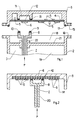
- FIG. 1 shows an electronic control unit with a Housing and a cover, which is a circuit board with a pressure sensor.
- Fig. 2 shows the lid of another electronic Control unit with a glued-in heat sink circuit board.
- 1 is an electronic control unit (1) shown, which consists of a housing (2) and a Cover (3).
- the cover (3) is on the housing (2) screwable.
- tabs (15, 16) are provided, wherein the tab (16) contains a threaded bore.
- the housing (2) and the cover (3) can be made of metal (Steel or aluminum) or made of plastic his.
- the housing (2) has another space (19) below which is, for example, a valve device can (not shown).
- the housing parts (18, 19) are separated from each other by a housing base (21) separated pressure-tight.
- the cover (3) of the housing (2) contains a printed circuit board (4) usual type, which with electronic Components (5) is equipped.
- the circuit board (4) can be multi-layered.
- Components (5) can either be in conventional design with push-through Connecting wires, or as SMD components be trained.
- the circuit board (4) can be on both sides be equipped.
- Components (5) is the circuit board (4) equipped with a pressure sensor (6), which like that other components (5) either as a conventional component, or can be designed as an SMD component.
- a Snorkel (7) To supply pressure to the pressure sensor (6) in the assembled Condition of housing (2) and cover (3) is a Snorkel (7), which in a bore (22) of the housing bottom (21) is glued in.
- the snorkel (7) exists from a tubular lower part (20) (see Fig. 2) and a cup-shaped widened upper Part (8).
- the pressure is supplied to the pressure sensor (6) by the tubular lower part (20) of the snorkel (7), which to a pressure chamber with the pressure to be measured (P) is connected.
- This can be a Pressure chamber of one installed in the lower housing part (19) Act valve.
- the copper coating the printed circuit board (4) in the area of the seal (10) advantageously be left standing.
- the Printed circuit board (4) to be multilayered, and the electrical connections for the pressure sensor (6) via conductor tracks inside the circuit board (4).
- a pressure compensation space (11) On the side of the snorkel (7) opposite Printed circuit board (4) is expediently a pressure compensation space (11) arranged. This has the same cross-sectional area like the upper part (8) of the snorkel (7).
- Pressure compensation bore (12) For Ventilation of the pressure compensation chamber (11) is used Pressure compensation bore (12), which in the area of Pressure sensor (6) penetrates the circuit board (4).
- the pressure compensation chamber (11) is with another Sealing ring (13) sealed against the circuit board (4).
- Purpose of the pressure compensation chamber (11) with the bore (12) is the same in front of and behind the circuit board (4) To get pressure. This will cause deflection the board (4) with snorkel (7) avoided under pressure.
- the diameter of the upper part (8) of the snorkel (7) can be round or angular.
- the cross-sectional area depends on the size of the pressure sensor (6) from. A typical value of the diameter is 1 cm.
- the maximum pressure (P) is about 10 up to 12 bar.
- the pressure compensation chamber can be used (11) also by means of a pressure-tight one Adhesion to be sealed. This would be cheaper than the version with sealing ring.
- the snorkel (7) projects so far with its upper part (8) beyond the housing (2) that during assembly of cover (3) and housing (2) by means of the screw connection (15, 16) a reliable seal between Snorkel (7) and circuit board (4) through the sealing ring (10) is done.
- FIG. 2 is a further embodiment of the electronic Control unit (1) shown. Is drawn the cover (3), in which a circuit board (14) is glued is. This is designed as a heat sink circuit board, which means that their backside with a Aluminum sheet of about 1 mm thickness is sealed, which serves for better heat dissipation.
- the electronic Components (5) are therefore only on one side of the circuit board soldered on and designed as SMD components.
- the snorkel (7) can, as described above, on the case bottom (21). But he can also with its lower part (20) on a side wall or the Frame of the housing (2) may be attached. If the case (2) Made of plastic, the snorkel can (7) e.g. B. with its lower part (20) on the frame of Housing (2) be molded.
- the interior (18) of the housing (2) is expedient ventilated on the outside, for example by a (not shown) Drilling. This prevents condensation from forming in the housing (2) and continues to hold the pressure in the interior (18) to atmospheric pressure. In this way an otherwise possible pressure increase in the interior (18) with a slight leak between the sealing ring (10) and printed circuit board (4, 14) prevented.
- the solution according to the invention is a simplification or cheaper construction of mechatronics possible with integrated pressure sensors.
- the use of expensive pressure sensor hybrids are avoided and instead whose the use of as an SMD component or as IC trained pressure sensors.
- the snorkel (7) directly on the circuit board (4, 14) the arrangement is insensitive to a lateral offset or lateral tolerances between housing (2) and cover (3).
Landscapes
- Physics & Mathematics (AREA)
- General Physics & Mathematics (AREA)
- Measuring Fluid Pressure (AREA)
- Cooling Or The Like Of Electrical Apparatus (AREA)
- Mounting Of Printed Circuit Boards And The Like (AREA)
Abstract
Description
Claims (17)
- Elektronisches Steuergerät (1) mit einem Gehäuse (2), einem Deckel (3) und mindestens einer Leiterplatte (4, 14), die mit elektronischen Bauelementen (5) bestückt ist, von welchen mindestens eines ein Drucksensor (6) ist, dadurch gekennzeichnet, daß zur Druckzufuhr (P) zum Drucksensor (6) ein Schnorchel (7) vorgesehen ist, welcher mit seinem oberen Teil (8) den Drucksensor (6) umschließt und dessen Rand (9) gegen die Leiterplatte (4, 14) abgedichtet ist.
- Elektronisches Steuergerät nach Anspruch 1, dadurch gekennzeichnet, daß der Rand (9) des Schnorchels (7) mit einem Dichtring (10) versehen ist.
- Elektronisches Steuergerät nach einem oder beiden der Ansprüche 1 und 2, dadurch gekennzeichnet, daß die Kupferbeschichtung der Leiterplatte (4, 14) im Bereich des Dichtrings (10) stehengelassen ist.
- Elektronisches Steuergerät nach Anspruch 3, dadurch gekennzeichnet, daß die Leiterplatte (4, 14) mehrschichtig ausgebildet ist, und die elektrischen Anschlüsse für den Drucksensor (6) über Leiterbahnen im Inneren der Leiterplatte (4, 14) erfolgt.
- Elektronisches Steuergerät nach einem oder mehreren der Ansprüche 1 bis 4, dadurch gekennzeichnet, daß auf der Rückseite der Leiterplatte (4) gegenüber dem Schnorchel (7) ein Druckausgleichsraum (11) mit gleicher Querschnittsfläche wie beim oberen Teil (8) des Schnorchels (7) vorgesehen ist.
- Elektronisches Steuergerät nach Anspruch 5, dadurch gekennzeichnet, daß die Leiterplatte (4) im Bereich des Schnorchels (7) eine Druckausgleichsbohrung (12) aufweist.
- Elektronisches Steuergerät nach Anspruch 6, dadurch gekennzeichnet, daß die Druckausgleichsbohrung (12) durchmetallisiert ist.
- Elektronisches Steuergerät nach Anspruch 5 bis 7, dadurch gekennzeichnet, daß der Druckausgleichsraum (11) mit einem weiteren Dichtring (13) abgedichtet ist.
- Elektronisches Steuergerät nach Anspruch 5 bis 7, dadurch gekennzeichnet, daß der Druckausgleichsraum (11) mittels einer druckdichten Klebung abgedichtet ist.
- Elektronisches Steuergerät nach einem oder mehreren der Ansprüche 1 bis 9, dadurch gekennzeichnet, daß die Leiterplatte (4) beidseitig mit steckbaren Bauelementen (5) oder mit SMD-Bauelementen (5) bestückt ist.
- Elektronisches Steuergerät nach Anspruch 1 bis 9, dadurch gekennzeichnet, daß die Leiterplatte (14) als Heat-Sink-Leiterplatte ausgebildet ist, und nur einseitig mit SMD-Bauelementen (5) bestückt ist.
- Elektronisches Steuergerät nach Anspruch 11, dadurch gekennzeichnet, daß die Rückseite der Heat-Sink-Leiterplatte (14) mit der Innenseite des Deckels (3) durch eine Klebung verbunden ist.
- Elektronisches Steuergerät nach einem oder mehreren der Ansprüche 1 bis 12, dadurch gekennzeichnet, daß der Schnorchel (7) am Gehäuse (2) befestigt ist.
- Elektronisches Steuergerät nach Anspruch 13, dadurch gekennzeichnet, daß der Schnorchel (7) in eine Bohrung (22) eines Gehäusebodens (21) eingeklebt ist.
- Elektronisches Steuergerät nach Anspruch 13, dadurch gekennzeichnet, daß der Schnorchel (7) mit seinem unteren Teil (20) an einer Seitenwand des Gehäuses (2) angespritzt ist.
- Elektronisches Steuergerät nach einem oder mehreren der Ansprüche 1 bis 15, dadurch gekennzeichnet, daß der Deckel (3) auf das Gehäuse (2) aufschraubbar ist.
- Elektronisches Steuergerät nach einem oder mehreren der Ansprüche 1 bis 16, dadurch gekennzeichnet, daß der Innenraum (18) des Gehäuses (2) nach aussen belüftet ist.
Applications Claiming Priority (2)
| Application Number | Priority Date | Filing Date | Title |
|---|---|---|---|
| DE10022124A DE10022124B4 (de) | 2000-05-06 | 2000-05-06 | Elektronisches Steuergerät |
| DE10022124 | 2000-06-05 |
Publications (3)
| Publication Number | Publication Date |
|---|---|
| EP1152231A2 true EP1152231A2 (de) | 2001-11-07 |
| EP1152231A3 EP1152231A3 (de) | 2003-07-16 |
| EP1152231B1 EP1152231B1 (de) | 2019-11-20 |
Family
ID=7641028
Family Applications (1)
| Application Number | Title | Priority Date | Filing Date |
|---|---|---|---|
| EP01106081.1A Expired - Lifetime EP1152231B1 (de) | 2000-05-06 | 2001-03-13 | Drucksensorvorrichtung |
Country Status (4)
| Country | Link |
|---|---|
| US (1) | US6640645B2 (de) |
| EP (1) | EP1152231B1 (de) |
| JP (1) | JP4560758B2 (de) |
| DE (1) | DE10022124B4 (de) |
Cited By (6)
| Publication number | Priority date | Publication date | Assignee | Title |
|---|---|---|---|---|
| DE102004053200A1 (de) * | 2004-11-04 | 2006-05-11 | Wabco Gmbh & Co.Ohg | Mechatronik |
| WO2010136292A1 (de) * | 2009-05-25 | 2010-12-02 | Robert Bosch Gmbh | Steuergerät mit drucksensor |
| US8413678B2 (en) | 2004-11-04 | 2013-04-09 | Wabco Gmbh | Mechatronic device |
| EP2365308A3 (de) * | 2010-02-22 | 2014-10-01 | Delphi Technologies, Inc. | Versiegeltes Motorsteuerungsmodul mit intregriertem Umgebungsluftdrucksensor |
| WO2017054902A1 (de) * | 2015-10-01 | 2017-04-06 | Wabco Gmbh | Fahrzeugsteuergerät |
| WO2018177833A1 (de) * | 2017-03-27 | 2018-10-04 | Knorr-Bremse Systeme für Nutzfahrzeuge GmbH | Steuergerät für ein fahrzeug mit wenigstens einem drucksensorelement |
Families Citing this family (13)
| Publication number | Priority date | Publication date | Assignee | Title |
|---|---|---|---|---|
| DE10051048A1 (de) * | 2000-10-14 | 2002-04-18 | Wabco Gmbh & Co Ohg | Meßverfahren für eine Mechatronik |
| JP3824964B2 (ja) * | 2002-05-17 | 2006-09-20 | 長野計器株式会社 | 絶対圧型圧力センサ |
| JP2004340891A (ja) | 2003-05-19 | 2004-12-02 | Mitsubishi Electric Corp | 圧力センサ装置 |
| EP1528282B1 (de) * | 2003-10-28 | 2007-09-19 | Zf Friedrichshafen Ag | Ventilgehäuse mit einer integrierten Schaltungsanordnung |
| DE102004007230B4 (de) * | 2004-02-13 | 2006-03-30 | Siemens Ag | Gehäuse mit flüssigkeitsdichter elektrischer Durchführung |
| DE102004028199A1 (de) | 2004-06-04 | 2005-12-22 | Wabco Gmbh & Co.Ohg | Elektronikgehäuse |
| US7117747B2 (en) * | 2005-01-03 | 2006-10-10 | Delphi Technologies, Inc. | Integrated pressure sensor and method of manufacture |
| US20080127742A1 (en) * | 2006-12-04 | 2008-06-05 | Andre Mueller | Pressure sensor having a check valve |
| DE102008040155A1 (de) | 2008-07-03 | 2010-01-07 | Robert Bosch Gmbh | Sensorgehäusedeckel und Verfahren zur Herstellung eines solchen Sensorgehäusedeckels |
| US20110079085A1 (en) * | 2009-10-06 | 2011-04-07 | Robert John Kanda | Integrated fluid pressure sensor system |
| DE102010015674A1 (de) | 2010-04-21 | 2011-10-27 | Wabco Gmbh | Ein Gehäuse mit einem Verformungsbereich zum Druckausgleich sowie eine Anordnung eines Dichtungselements in dem Gehäuse |
| DE102014209874A1 (de) * | 2014-05-23 | 2015-11-26 | Conti Temic Microelectronic Gmbh | Steuergerät für ein Fahrzeug mit einem einen Drucksensor aufweisenden Gehäuse |
| KR102458252B1 (ko) * | 2021-04-12 | 2022-10-21 | 주식회사 현대케피코 | 전자 제어 장치 |
Citations (1)
| Publication number | Priority date | Publication date | Assignee | Title |
|---|---|---|---|---|
| DE29602711U1 (de) | 1996-02-16 | 1996-04-11 | Duerrwaechter E Dr Doduco | Anordnung aus einer elektrischen Leiterplatte und einem elektrischen Druckaufnehmer |
Family Cites Families (16)
| Publication number | Priority date | Publication date | Assignee | Title |
|---|---|---|---|---|
| JPS5817421B2 (ja) * | 1979-02-02 | 1983-04-07 | 日産自動車株式会社 | 半導体圧力センサ |
| JPS56140230A (en) * | 1980-04-04 | 1981-11-02 | Hitachi Ltd | Semiconductor pressure converter |
| US4683758A (en) * | 1986-01-16 | 1987-08-04 | Ford Motor Company | Device for measuring stresses in vacuum deposition coatings |
| DE4206675C2 (de) * | 1992-02-28 | 1995-04-27 | Siemens Ag | Verfahren zum Herstellen von Druckdifferenz-Sensoren |
| JP2536232Y2 (ja) * | 1993-08-31 | 1997-05-21 | エスエムシー株式会社 | 圧力検出器 |
| DE4334123C2 (de) * | 1993-10-07 | 2002-12-19 | Bosch Gmbh Robert | Drucksensor |
| JPH08210935A (ja) * | 1995-02-07 | 1996-08-20 | Tokai Rika Co Ltd | 圧力センサ |
| JPH08233848A (ja) * | 1995-02-28 | 1996-09-13 | Mitsubishi Electric Corp | 半導体センサ |
| DE19605795A1 (de) * | 1996-02-16 | 1997-08-21 | Duerrwaechter E Dr Doduco | Anordnung aus einer elektrischen Leiterplatte und einem elektrischen Druckaufnehmer |
| JPH09222372A (ja) * | 1996-02-19 | 1997-08-26 | Mitsubishi Electric Corp | 半導体式センサ |
| DE19626084C2 (de) * | 1996-06-28 | 2003-04-17 | Infineon Technologies Ag | Drucksensorvorrichtung für eine Montage auf der Bestückungsoberfläche einer Leiterplatte |
| DE19707503B4 (de) * | 1997-02-25 | 2007-01-04 | Infineon Technologies Ag | Drucksensor-Bauelement und Verfahren zur Herstellung |
| JPH10332505A (ja) * | 1997-05-30 | 1998-12-18 | Matsushita Electric Works Ltd | 半導体圧力センサ |
| JPH1130559A (ja) * | 1997-07-10 | 1999-02-02 | Fuji Koki Corp | 圧力センサ |
| JP3319990B2 (ja) * | 1997-08-29 | 2002-09-03 | 三菱電機株式会社 | 圧力センサ装置 |
| US6311561B1 (en) * | 1997-12-22 | 2001-11-06 | Rosemount Aerospace Inc. | Media compatible pressure sensor |
-
2000
- 2000-05-06 DE DE10022124A patent/DE10022124B4/de not_active Expired - Lifetime
-
2001
- 2001-03-13 EP EP01106081.1A patent/EP1152231B1/de not_active Expired - Lifetime
- 2001-04-23 US US09/841,549 patent/US6640645B2/en not_active Expired - Fee Related
- 2001-04-27 JP JP2001168828A patent/JP4560758B2/ja not_active Expired - Lifetime
Patent Citations (1)
| Publication number | Priority date | Publication date | Assignee | Title |
|---|---|---|---|---|
| DE29602711U1 (de) | 1996-02-16 | 1996-04-11 | Duerrwaechter E Dr Doduco | Anordnung aus einer elektrischen Leiterplatte und einem elektrischen Druckaufnehmer |
Cited By (9)
| Publication number | Priority date | Publication date | Assignee | Title |
|---|---|---|---|---|
| DE102004053200A1 (de) * | 2004-11-04 | 2006-05-11 | Wabco Gmbh & Co.Ohg | Mechatronik |
| US8413678B2 (en) | 2004-11-04 | 2013-04-09 | Wabco Gmbh | Mechatronic device |
| DE102005036663B4 (de) * | 2004-11-04 | 2014-10-02 | Wabco Gmbh | Mechatronik I |
| WO2010136292A1 (de) * | 2009-05-25 | 2010-12-02 | Robert Bosch Gmbh | Steuergerät mit drucksensor |
| EP2365308A3 (de) * | 2010-02-22 | 2014-10-01 | Delphi Technologies, Inc. | Versiegeltes Motorsteuerungsmodul mit intregriertem Umgebungsluftdrucksensor |
| WO2017054902A1 (de) * | 2015-10-01 | 2017-04-06 | Wabco Gmbh | Fahrzeugsteuergerät |
| US10724916B2 (en) | 2015-10-01 | 2020-07-28 | Wabco Gmbh | Vehicle control device |
| WO2018177833A1 (de) * | 2017-03-27 | 2018-10-04 | Knorr-Bremse Systeme für Nutzfahrzeuge GmbH | Steuergerät für ein fahrzeug mit wenigstens einem drucksensorelement |
| US11156524B2 (en) | 2017-03-27 | 2021-10-26 | Knorr-Bremse Systeme Fuer Nutzfahrzeuge Gmbh | Breaking device including an electronic control unit for pressure measurements |
Also Published As
| Publication number | Publication date |
|---|---|
| DE10022124A1 (de) | 2001-11-08 |
| US20010049965A1 (en) | 2001-12-13 |
| EP1152231A3 (de) | 2003-07-16 |
| EP1152231B1 (de) | 2019-11-20 |
| DE10022124B4 (de) | 2010-01-14 |
| JP2002055010A (ja) | 2002-02-20 |
| JP4560758B2 (ja) | 2010-10-13 |
| US6640645B2 (en) | 2003-11-04 |
Similar Documents
| Publication | Publication Date | Title |
|---|---|---|
| EP1152231B1 (de) | Drucksensorvorrichtung | |
| DE19923985B4 (de) | Sensorbaugruppe mit einem an einer Wand montierbaren Gehäuse | |
| DE19936300B4 (de) | Druckerkennungsvorrichtung und Druckerkennungsvorrichtung-Anordnung hiermit | |
| EP0555434B1 (de) | Elektrisches gerät, insbesondere schalt- und steuergerät für kraftfahrzeuge | |
| DE102006039260B4 (de) | Kühlanordnung, Elektronikmodul und Audioverstärker | |
| EP1006766B1 (de) | Elektronische Vorrichtung | |
| DE19834212A1 (de) | Steuergerät in einem Kraftfahrzeug und von diesem verwendeter Drucksensor | |
| DE4232048A1 (de) | Elektronisches Steuergerät | |
| DE102006053407A1 (de) | Standardisiertes Elektronikgehäuse mit modularen Kontaktpartnern | |
| WO2008049724A1 (de) | Gehäuse für ein elektronisches steuergerät | |
| EP1976357B1 (de) | Gehäuse für eine elektrische Schaltung und Verfahren zum Schließen eines entsprechenden Gehäuses | |
| DE102007019098B4 (de) | Modul für eine integrierte Steuerelektronik mit vereinfachtem Aufbau | |
| EP1572501B1 (de) | Elektromechanische baugruppe | |
| DE102006039949B4 (de) | Elektrohydraulische Steuervorrichtung | |
| EP2964979B1 (de) | Mehrstufiges dichtsystem zum einsatz in einem kraftfahrzeugsteuergerät | |
| DE102004007230B4 (de) | Gehäuse mit flüssigkeitsdichter elektrischer Durchführung | |
| EP1317630A2 (de) | Hydraulischer zylinder | |
| DE10235228A1 (de) | Abdeckung für eine elektronische Verbindung für ein Gehäuse einer Hydraulikeinheit unter Verwendung einer abgedichteten Leiterplatte | |
| WO1992016089A1 (de) | Elektrisches gerät, insbesondere schalt- oder steuergerät für kraftfahrzeuge | |
| DE19612599A1 (de) | Anordnung zur Befestigung eines Kabelbaums an einer Trägerplatte | |
| DE102006052458B4 (de) | Elektronikgehäuse mit neuer flexibler Leiterplattentechnologie | |
| DE3011269A1 (de) | Druck-messeinrichtung | |
| EP0884938B1 (de) | Elektronische Baueinheit mit einer metallischen Abschirmung bei einem Anschlussbereich | |
| DE102021205841A1 (de) | Gehäuse für eine elektronische Einheit und Sensorsystem mit einem Gehäuse | |
| DE2722798C2 (de) | Leuchte mit einer Hochleistungslampe |
Legal Events
| Date | Code | Title | Description |
|---|---|---|---|
| PUAI | Public reference made under article 153(3) epc to a published international application that has entered the european phase |
Free format text: ORIGINAL CODE: 0009012 |
|
| AK | Designated contracting states |
Kind code of ref document: A2 Designated state(s): AT BE CH CY DE DK ES FI FR GB GR IE IT LI LU MC NL PT SE TR |
|
| AX | Request for extension of the european patent |
Free format text: AL;LT;LV;MK;RO;SI |
|
| PUAL | Search report despatched |
Free format text: ORIGINAL CODE: 0009013 |
|
| AK | Designated contracting states |
Designated state(s): AT BE CH CY DE DK ES FI FR GB GR IE IT LI LU MC NL PT SE TR |
|
| AX | Request for extension of the european patent |
Extension state: AL LT LV MK RO SI |
|
| RIC1 | Information provided on ipc code assigned before grant |
Ipc: 7G 01L 9/00 B Ipc: 7G 01L 19/00 B Ipc: 7G 01L 9/06 A |
|
| 17P | Request for examination filed |
Effective date: 20040116 |
|
| AKX | Designation fees paid |
Designated state(s): DE FR GB IT SE |
|
| RAP1 | Party data changed (applicant data changed or rights of an application transferred) |
Owner name: WABCO GMBH |
|
| 17Q | First examination report despatched |
Effective date: 20061208 |
|
| APBK | Appeal reference recorded |
Free format text: ORIGINAL CODE: EPIDOSNREFNE |
|
| APBN | Date of receipt of notice of appeal recorded |
Free format text: ORIGINAL CODE: EPIDOSNNOA2E |
|
| APBR | Date of receipt of statement of grounds of appeal recorded |
Free format text: ORIGINAL CODE: EPIDOSNNOA3E |
|
| APAF | Appeal reference modified |
Free format text: ORIGINAL CODE: EPIDOSCREFNE |
|
| APBX | Invitation to file observations in appeal sent |
Free format text: ORIGINAL CODE: EPIDOSNOBA2E |
|
| APBZ | Receipt of observations in appeal recorded |
Free format text: ORIGINAL CODE: EPIDOSNOBA4E |
|
| APAQ | Information on invitation to file observation in appeal modified |
Free format text: ORIGINAL CODE: EPIDOSCOBA2E |
|
| APBH | Information on receipt of observation in appeal deleted |
Free format text: ORIGINAL CODE: EPIDOSDOBA4E |
|
| APBZ | Receipt of observations in appeal recorded |
Free format text: ORIGINAL CODE: EPIDOSNOBA4E |
|
| APBT | Appeal procedure closed |
Free format text: ORIGINAL CODE: EPIDOSNNOA9E |
|
| GRAP | Despatch of communication of intention to grant a patent |
Free format text: ORIGINAL CODE: EPIDOSNIGR1 |
|
| INTG | Intention to grant announced |
Effective date: 20190812 |
|
| GRAS | Grant fee paid |
Free format text: ORIGINAL CODE: EPIDOSNIGR3 |
|
| GRAA | (expected) grant |
Free format text: ORIGINAL CODE: 0009210 |
|
| AK | Designated contracting states |
Kind code of ref document: B1 Designated state(s): DE FR GB IT SE |
|
| REG | Reference to a national code |
Ref country code: GB Ref legal event code: FG4D Free format text: NOT ENGLISH |
|
| REG | Reference to a national code |
Ref country code: DE Ref legal event code: R096 Ref document number: 50116696 Country of ref document: DE |
|
| PG25 | Lapsed in a contracting state [announced via postgrant information from national office to epo] |
Ref country code: SE Free format text: LAPSE BECAUSE OF FAILURE TO SUBMIT A TRANSLATION OF THE DESCRIPTION OR TO PAY THE FEE WITHIN THE PRESCRIBED TIME-LIMIT Effective date: 20191120 |
|
| PGFP | Annual fee paid to national office [announced via postgrant information from national office to epo] |
Ref country code: GB Payment date: 20200325 Year of fee payment: 20 |
|
| PGFP | Annual fee paid to national office [announced via postgrant information from national office to epo] |
Ref country code: FR Payment date: 20200325 Year of fee payment: 20 |
|
| PGFP | Annual fee paid to national office [announced via postgrant information from national office to epo] |
Ref country code: DE Payment date: 20200331 Year of fee payment: 20 |
|
| REG | Reference to a national code |
Ref country code: DE Ref legal event code: R097 Ref document number: 50116696 Country of ref document: DE |
|
| PLBE | No opposition filed within time limit |
Free format text: ORIGINAL CODE: 0009261 |
|
| STAA | Information on the status of an ep patent application or granted ep patent |
Free format text: STATUS: NO OPPOSITION FILED WITHIN TIME LIMIT |
|
| 26N | No opposition filed |
Effective date: 20200821 |
|
| PG25 | Lapsed in a contracting state [announced via postgrant information from national office to epo] |
Ref country code: IT Free format text: LAPSE BECAUSE OF FAILURE TO SUBMIT A TRANSLATION OF THE DESCRIPTION OR TO PAY THE FEE WITHIN THE PRESCRIBED TIME-LIMIT Effective date: 20191120 |
|
| REG | Reference to a national code |
Ref country code: DE Ref legal event code: R071 Ref document number: 50116696 Country of ref document: DE |
|
| REG | Reference to a national code |
Ref country code: GB Ref legal event code: PE20 Expiry date: 20210312 |
|
| PG25 | Lapsed in a contracting state [announced via postgrant information from national office to epo] |
Ref country code: GB Free format text: LAPSE BECAUSE OF EXPIRATION OF PROTECTION Effective date: 20210312 |