EP1151868B1 - Procédé utilisant l'éjection hautement énergétique des gouttelettes pour améliorer la fiabilité de l'éjection des gouttelettes - Google Patents
Procédé utilisant l'éjection hautement énergétique des gouttelettes pour améliorer la fiabilité de l'éjection des gouttelettes Download PDFInfo
- Publication number
- EP1151868B1 EP1151868B1 EP01303688A EP01303688A EP1151868B1 EP 1151868 B1 EP1151868 B1 EP 1151868B1 EP 01303688 A EP01303688 A EP 01303688A EP 01303688 A EP01303688 A EP 01303688A EP 1151868 B1 EP1151868 B1 EP 1151868B1
- Authority
- EP
- European Patent Office
- Prior art keywords
- energy
- printhead assembly
- ink
- printhead
- predetermined
- Prior art date
- Legal status (The legal status is an assumption and is not a legal conclusion. Google has not performed a legal analysis and makes no representation as to the accuracy of the status listed.)
- Expired - Lifetime
Links
Images


Classifications
-
- B—PERFORMING OPERATIONS; TRANSPORTING
- B41—PRINTING; LINING MACHINES; TYPEWRITERS; STAMPS
- B41J—TYPEWRITERS; SELECTIVE PRINTING MECHANISMS, i.e. MECHANISMS PRINTING OTHERWISE THAN FROM A FORME; CORRECTION OF TYPOGRAPHICAL ERRORS
- B41J2/00—Typewriters or selective printing mechanisms characterised by the printing or marking process for which they are designed
- B41J2/005—Typewriters or selective printing mechanisms characterised by the printing or marking process for which they are designed characterised by bringing liquid or particles selectively into contact with a printing material
- B41J2/01—Ink jet
- B41J2/135—Nozzles
- B41J2/165—Preventing or detecting of nozzle clogging, e.g. cleaning, capping or moistening for nozzles
- B41J2/16517—Cleaning of print head nozzles
- B41J2/1652—Cleaning of print head nozzles by driving a fluid through the nozzles to the outside thereof, e.g. by applying pressure to the inside or vacuum at the outside of the print head
- B41J2/16526—Cleaning of print head nozzles by driving a fluid through the nozzles to the outside thereof, e.g. by applying pressure to the inside or vacuum at the outside of the print head by applying pressure only
Definitions
- This invention relates to thermal inkjet printers, and more particularly to the control of the printhead firing energy.
- Thermal inkjet hardcopy devices such as printers, graphics plotters, facsimile machines and copiers have gained wide acceptance. These hardcopy devices are described by W.J. Lloyd and H.T. Taub in "Ink Jet Devices," Chapter 13 of Output Hardcopy Devices (Ed. R.C. Durbeck and S. Sherr, San Diego: Academic Press, 1988). The basics of this technology are further disclosed in various articles in several editions of the Hewlett-Packard Journal [Vol. 36, No. 5 (May 1985), Vol. 39, No. 4 (August 1988), Vol. 39, No. 5 (October 1988), Vol. 43, No. 4 (August 1992), Vol. 43, No. 6 (December 1992) and Vol. 45, No.1 (February 1994)]. Inkjet hardcopy devices produce high quality print, are compact and portable, and print quickly and quietly because only ink strikes the paper.
- An inkjet printer forms a printed image by printing a pattern of individual dots at particular locations of an array defined for the printing medium.
- the locations are conveniently visualized as being small dots in a rectilinear array.
- the locations are sometimes "dot locations", “dot positions”, or pixels".
- the printing operation can be viewed as the filling of a pattern of dot locations with dots of ink.
- Inkjet hardcopy devices print dots by ejecting very small drops of ink onto the print medium and typically include a movable carriage that supports one or more printheads each having ink ejecting ink ejection elements.
- the carriage traverses over the surface of the print medium, and the ink ejection elements are controlled to eject drops of ink at appropriate times pursuant to command of a microcomputer or other controller, wherein the timing of the application of the ink drops is intended to correspond to the pattern of pixels of the image being printed.
- the typical inkjet printhead i.e., the silicon substrate, structures built on the substrate, and connections to the substrate
- liquid ink i.e., dissolved colorants or pigments dispersed in a solvent
- It has an array of precisely formed orifices or nozzles attached to a printhead substrate that incorporates an array of ink ejection chambers which receive liquid ink from the ink reservoir.
- Each chamber is located opposite the nozzle so ink can collect between it and the nozzle and has a firing resistor located in the chamber.
- the ejection of ink droplets is typically under the control of a microprocessor, the signals of which are conveyed by electrical traces to the resistor elements.
- inkjet printhead In an inkjet printhead the ink is fed from an ink reservoir integral to the printhead or an "off-axis" ink reservoir which feeds ink to the printhead via tubes connecting the printhead and reservoir. Ink is then fed to the various vaporization chambers either through an elongated hole formed in the center of the bottom of the substrate, "center feed”, or around the outer edges of the substrate, “edge feed”.
- the ink cartridge containing the ink ejection elements is moved repeatedly across the width of the medium to be printed upon.
- each of the resistors is caused either to eject ink or to refrain from ejecting ink according to the program output of the controlling microprocessor.
- Each completed movement across the medium can print a swath approximately as wide as the number of nozzles arranged in a column of the ink cartridge multiplied times the distance between nozzle centers. After each such completed movement or swath the medium is moved forward the width of the swath, and the ink cartridge begins the next swath. By proper selection and timing of the signals, the desired print is obtained on the medium.
- Thermal inkjet printheads require an electrical drive pulse from a printer in order to eject a drop of ink.
- the voltage amplitude, shape and width of the pulse affect the printhead's performance. It is desirable to operate the printhead using pulses that deliver a specified amount of energy. The energy delivered depends on the pulse characteristics (width, amplitude, shape), as well as the resistance of the printhead.
- a thermal inkjet printhead requires a certain minimum energy to fire ink drops of the proper volume (herein called the turn-on energy).
- Turn-on energy can be different for different printhead designs, and in fact varies among different samples of a given printhead design as a result of manufacturing tolerances.
- the total resistance consists of the heater resistance in series with a field effect transistor and other trace resistances, each of which has an associated manufacturing tolerance.
- thermal inkjet printers are configured to provide a fixed ink firing energy that is greater than the expected lowest turn-on energy for the printhead cartridges it can accommodate.
- a consideration with utilizing a fixed ink firing energy is that firing energies excessively greater than the actual turn-on energy of a particular printhead cartridge result in a shorter operating lifetime for the heater resistors and degraded print quality.
- the energy applied to a firing resistor affects performance, durability and efficiency. It is well known that the firing energy must be above a certain firing threshold to cause a vapor bubble to nucleate. Above this firing threshold is a transitional range where increasing the firing energy increases the volume of ink expelled. Above this transitional range, there is a higher optimal range where drop volumes do not increase with increasing firing energy. In this optimal range above the optimal firing threshold drop volumes are stable even with moderate firing energy variations. Since, variations in drop volume cause uniformities in printed output, it is in this optimal range that printing ideally takes place. As energy levels increase in this optimal range, uniformity is not compromised, but energy is wasted and the printhead is prematurely aged due to excessive heating and ink residue build-up.
- each firing resistor or each primitive does not have a dedicated connection
- a large number of resistors is powered by a single voltage line that receives power via an electrical contact pad between the printer electronics and the removable print cartridge. Consequently, as the data load being printed changes, the current draw through the line and the voltage as measured at the firing resistor may be undesirably varied. For instance, when many or all resistors are fired simultaneously, the print cartridge voltage may be depressed by parasitic effects, giving a lower firing voltage than when only one or a few resistors are fired.
- Inkjet print cartridges can suffer from droplet ejection problems caused by formation of bubbles in the firing chamber that can cause misdirected ejection or no ejection at all. They occur when a particular nozzle has been inactive for some period of time. When a page is printed not all nozzles on a print cartridge are necessarily used. During this time of inactivity, these nozzles are often at high temperatures. Especially in pigmented ink systems, reliability problems arise due to bubbles in the firing chamber. These bubbles can induce droplet trajectory errors, or can cause a nozzle to fail completely. Bubbles form during a pause in printing for a particular nozzle. The sensitivity of a particular inkjet system to bubbles is highly dependent on the ink formulation, the geometry of the nozzle and firing chamber; and temperature.
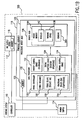
- FIG. 1A shows a block diagram of an overall printing system incorporating the present invention.
- FIG. 1B shows a block diagram of an overall printing system incorporating a preferred embodiment of the present invention.
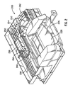
- FIG. 2 is an exemplary printer that incorporates the invention and is shown for illustrative purposes only.
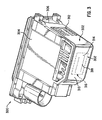
- FIG. 3 shows for illustrative purposes only a perspective view of an exemplary print cartridge incorporating the present invention.
- FIG. 4 is a detailed view of the integrated processing driver head of FIG. 3 showing the distributive processor and the resistor and primitive layout of the driver head of the printhead assembly.
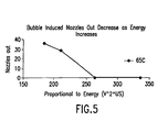
- FIG. 5 shows the effects of bubble induced nozzles out as energy is increased.
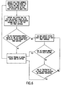
- FIG. 6 is a flow diagram illustrating one embodiment of the present invention.
- FIG. 6 is a flow diagram illustrating one embodiment of the present invention.
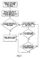
- FIG. 7 is a flow diagram illustrating anothe embodiment of the present invention.
- FIG. 1A shows a block diagram of an overall printing system incorporating the present invention.
- the printing system 100 can be used for printing a material, such as ink on a print media, which can be paper.
- the printing system 100 is electrically coupled to a host system 106, which can be a computer or microprocessor for producing print data.
- the printing system 100 includes a controller 110 coupled to an ink supply device 112, a power supply 114 and a printhead assembly 116.
- the ink supply device 112 includes an ink supply memory device 118 and is fluidically coupled to the printhead assembly 116 for selectively providing ink to the printhead assembly 116.
- the printhead assembly 116 includes a processing driver head 120 and a printhead memory device 122.
- the processing driver head 120 is comprised of a data processor 124, such as a distributive processor, and a driver head 126, such as an array of inkjet ink ejection elements or drop generators 416.
- the power supply 114 provides a controlled voltage to the controller 110 and the processing driver head 120. Also, the controller 110 receives the print data from the host system and processes the data into printer control information and image data. The processed data, image data and other static and dynamically generated data (discussed in detail below), is exchanged with the ink supply device 112 and the printhead assembly 116 for efficiently controlling the printing system.
- the ink supply memory device 118 can store various ink supply specific data, including ink identification data, ink characterization data, ink usage data and the like.
- the ink supply data can be written and stored in the ink supply memory device 118 at the time the ink supply device 112 is manufactured or during operation of the printing system 100.
- the printhead memory device 122 can store various printhead specific data, including printhead identification data, warranty data, printhead characterization data, printhead usage data, etc. This data can be written and stored in the printhead memory device 122 at the time the printhead assembly 116 is manufactured or during operation of the printing system 100.
- the data processor 124 can communicate with memory devices 118, 122, the data processor 124 preferably primarily communicates with the controller 110 in a bi-directional manner.
- the bi-directional communication enables the data processor 124 to dynamically formulate and perform its own firing and timing operations based on sensed and given operating information for regulating the temperature of, and the energy delivered to the processing driver head 120. These formulated decisions are preferably based on, among other things, sensed printhead temperatures, sensed amount of power supplied, real time tests, and preprogrammed known optimal operating ranges, such as temperature and energy ranges.
- the data processor 124 enables efficient operation of the processing driver head 120 and produces droplets of ink that are printed on a print media to form a desired pattern for generating enhanced printed outputs.
- FIG. 1B shows a block diagram of an overall printing system 100 incorporating the preferred embodiment of the present invention.
- the data processor 124 of the present invention further includes a firing controller 130, an energy control device 132, a digital function device 134 and a thermal control device 136.
- the driver head 126 further includes a warming device 138 and sensors 140.
- the firing controller 130, energy control device 132, digital function device 134, thermal control device 136, warming device 138 and sensors 140 could be sub-components of other components, such as controller 110, in a preferred embodiment they are respective sub-components of the data processor 124 and the driver head 126, as shown FIG. 1B.
- the firing controller 130 communicates with the controller 110 and the driver head 126 (in another embodiment it also communicates with the printhead assembly memory device 122) for regulating the firing of ink ejection elements 416 of associated nozzles 142 of nozzle member 144.
- the firing controller 130 includes a firing sequence sub-controller 150 for selectively controlling the sequence of fire pulses, a firing delay sub-controller 152 for reducing electromagnetic interference in the processing driver head 120 and a fractional delay sub-controller 154 for compensating for scan axis directionality errors of the driver head 126.
- the energy control device 132 communicates with the controller 110 and the sensors 140 of the driver head 126 for regulating the energy delivered to the driver head 126.
- the thermal control device 136 communicates with the controller 110 and the sensors 140 and the warming device 138 of the driver head 126 for regulating the thermal characteristics of the driver head 126.
- the thermal control device 136 accomplishes this by activating the warming device 138 when the sensors 140 indicate that the driver head 126 is below a threshold temperature.
- energy and thermal control devices 132,136 also communicate with the printhead assembly memory device 122.
- the digital functions device 134 manages internal register operations and processing tasks of the data processor 124.
- FIG. 2 is an exemplary high-speed printer that incorporates the invention and is shown for illustrative purposes only.
- printer 200 can incorporate the printing system 100 of FIG. 1A and further include a tray 222 for holding print media.
- print media such as paper
- the sheet then brought around in a U direction and travels in an opposite direction toward output tray 228.
- Other paper paths such as a straight paper path, can also be used.
- the sheet is stopped in a print zone 230, and a scanning carriage 234, supporting one or more printhead assemblies 236 (an example of printhead assembly 116 of FIG.
- Spittoon 250 is located on the right side just out of the print zone of printer 200. During printing operation if spitting is required the carriage 234 moves the print cartridges 236 beyond the print zone so the print cartridges 236 can spit over the spittoon 250. While in Fig.
- the spittoon 250 is shown only on the right side of the print zone, a spittoon can be placed on both sides of the print zone so that the print cartridges 236 can spit on both sides of the print zone when the carriage 234 moves the cartridges 236 beyond the print zone on either side. Also shown is the capping station 252 where the print cartridges 236 are individually capped by caps 254 when not printing.
- the present invention is equally applicable to alternative printing systems (not shown) that utilize alternative media and/or printhead moving mechanisms, such as those incorporating grit wheel, roll feed or drum technology to support and move the print media relative to the printhead assemblies 236.
- a grit wheel design a grit wheel and pinch roller move the media back and forth along one axis while a carriage carrying one or more printhead assemblies scans past the media along an orthogonal axis.
- a drum printer design the media is mounted to a rotating drum that is rotated along one axis while a carriage carrying one or more printhead assemblies scans past the media along an orthogonal axis. In either the drum or grit wheel designs, the scanning is typically not done in a back and forth manner as is the case for the system depicted in FIG. 2.
- the print assemblies 236 can be removably mounted or permanently mounted to the scanning carriage 234.
- the printhead assemblies 236 can have self-contained ink reservoirs (for example, the reservoir can be located within printhead body 304 of FIG. 3).
- each print cartridge 236 can be fluidically coupled, via a flexible conduit 240, to one of a plurality of fixed or removable ink containers 242 acting as the ink supply 112 of FIG. 1A.
- the ink supplies 112 can be one or more ink containers separate or separable from printhead assemblies 116 and removably mountable to carriage 234.
- FIG. 3 shows for illustrative purposes only a perspective view of an exemplary printhead assembly 300 (an example of the printhead assembly 116 of FIG. 1) incorporating the present invention.
- a detailed description of the present invention follows with reference to a typical printhead assembly used with a typical printer, such as printer 200 of FIG. 2.
- the present invention can be incorporated in any printhead and printer configuration.
- the printhead assembly 300 is comprised of a thermal inkjet head assembly 302, a printhead body 304 and a printhead memory device 306, which is an example of memory device 122 and discussed in detail in FIG. 5 below.
- the thermal head assembly 302 can be a flexible material commonly referred to as a Tape Automated Bonding (TAB) assembly and can contain a processing driver head 310 (an example of processing driver head 120 of FIG. 1) and interconnect contact pads 312.
- TAB Tape Automated Bonding
- the interconnect contact pads 312 are suitably secured to the print cartridge 300, for example, by an adhesive material.
- the contact pads 312 align with and electrically contact electrodes (not shown) on carriage 234 of FIG. 2.
- the processing driver head 310 comprises a distributive processor 314 (an example of the data processor 124 of FIG. 1) preferably integrated with a nozzle member 316 (an example of driver head 126 of FIG. 1).
- the nozzle member 316 preferably contains plural orifices or nozzles 318, which can be created by, for example, laser ablation, for creating ink drop generation on a print media.
- the distributive processor 314 preferably includes digital circuitry and communicates via electrical signals with the controller 110, nozzle member 316 and various analog devices, such as temperature sensors which can be located on the nozzle member 316.
- the distributive processor 314 communicates with the controller in a bi-directional manner over a bi-directional data line.
- the controller sends commands to the distributive processor and receives and processes signals from the distributive processor.
- the distributive processor 314 makes decisions and actions based on its input signals. For example, controlling firing, timing, thermal and energy aspects and pulse width decisions of the printhead assembly 300 and nozzle member 316 timing can be made by the distributive processor. These decisions may alternatively may be made by the controller 110 of the printing system.
- the distributive processor 314 also receives sensor signals from sensors 140 located on the driver head 310. The sensors 140 can also be connected to the controller 110 via a direct connection or through the printer's memory device for continuously updating the controller.
- FIG. 4 is a detailed view of an exemplary integrated processing driver head of FIG. 3 showing the distributive processor and the driver head of the printhead assembly.
- the elements of FIG. 4 are not to scale and are exaggerated for simplification.
- conductors (not shown) are formed on the back of TAB head assembly 302 and terminate in contact pads 312 for contacting electrodes on carriage 234.
- the electrodes on carriage 234 are coupled to the controller 110 and power supply 114 for providing communication with the thermal head assembly 302.
- the other ends of the conductors are bonded to the processing driver head 310 via terminals or electrodes on substrate 410.
- the substrate 410 has ink ejection elements 416 formed thereon and electrically coupled to the conductors.
- the controller 110 and distributive processor 314 provide the ink ejection elements 416 with operational electrical signals.
- a barrier layer (not shown) is formed on the surface of the substrate 410 to define ink ejection chambers, preferably using photo lithographic techniques, and can be a layer of photo resist or some other polymer.
- the ink ejection chamber (not shown) contains an ink ejection element 416 and is preferably located behind a single nozzle 318 of the nozzle member 316. A portion of the barrier layer insulates the conductive traces from the underlying substrate 410.
- Each ink ejection element 416 ejects ink when selectively energized by one or more pulses applied sequentially or simultaneously to one or more of the contact pads 312.
- the ink ejection elements 416 may be heater resistors or piezoelectric elements.
- Each ink ejection element 416 is allocated to a specific group of ink ejection elements 416, hereinafter referred to as a primitive 420.
- the processing driver head 310 may be arranged into any number of multiple subsections with each subsection having a particular number of primitives containing a particular number of ink ejection elements 416.
- the nozzles 318 may be of any size, number, and pattern, and the various figures are designed to simply and clearly show the features of the invention. The relative dimensions of the various features have been greatly adjusted for the sake of clarity.
- the processing driver head 310 has 192 nozzles with 192 associated firing ink ejection elements 416.
- the primitives in each column have 8 resistors each for a total of 192 resistors.
- the ink ejection elements 416 on one side all have odd numbers, starting at the first resistor (R1) and continuing to the third resistor (R3), fifth resistor (R5) and so on.
- the ink ejection elements 416 on the other side all have even numbers, starting at the second resistor (R2) and continuing to the fourth resistor (R4), sixth resistor (R6) and so on.
- the print driver circuitry comprises an array of primitive lines, primitive commons, and address select lines to control ink ejections elements 416. Specifying an address line and a primitive line uniquely identifies one particular ink ejection element 416.
- the number of ink ejection elements 416 within a primitive is equal to the number of address lines. Any combination of address lines and primitive select lines could be used, however, it is useful to minimize the number of address lines in order to minimize the time required to cycle through the address lines.
- Each ink ejection element 416 is controlled by its own drive transistor which shares its control input address select with the number of ejection elements 416 in a primitive.
- Each ink ejection element 416 is tied to other ink ejection elements 416 by a common node primitive select. Consequently, firing a particular ink ejection element 416 requires applying a control voltage at its address select terminal and an electrical power source at its primitive select terminal.
- each primitive is selectively energized by powering the associated primitive select interconnection. To provide uniform energy per heater ink ejection element 416 only one ink ejection element is energized at a time per primitive. However, any number of the primitive selects may be enabled concurrently.
- Each enabled primitive select thus delivers both power and one of the enable signals to the driver transistor.
- the other enable signal is an address signal provided by each address select line only one of which is active at a time.
- Each address select line is tied to all of the switching transistors so that all such switching devices are conductive when the interconnection is enabled.
- a primitive select interconnection and an address select line for a ink ejection element 416 are both active simultaneously, that particular heater ink ejection element 416 is energized. Only one address select line is enabled at one time. This ensures that the primitive select and group return lines supply current to at most one ink ejection element 416 at a time. Otherwise, the energy delivered to a heater ink ejection element 416 would be a function of the number of ink ejection elements 416 being energized at the same time.
- the processing driver head 120 is comprised of a data processor 124, such as a distributive processor 314, and a driver head 126, such as an array of inkjet ink ejection elements for ejecting ink drops.
- the sensors 140 can be temperature sensors for controlling the energy delivered to, and the temperature of, the printhead assembly 116.
- the power supply 114 provides a controlled voltage or voltages to the printer controller 110 and the processing driver head 120.
- the data processor 124 can communicate with the controller 110 in a bi-directional manner with serial data communications.
- the bi-directional communication enables the data processor 124, 314 to dynamically formulate and perform its own firing and timing operations based on sensed and given operating information for regulating the temperature of, and the energy delivered to the printhead assembly 116. These formulated decisions are based on printhead temperatures sensed by the sensors 140, sensed amount of power supplied and pre-programmed known optimal operating ranges, such as temperature and energy ranges, scan axis directionality errors, etc.
- serial communications allows the addition of ink ejection elements 416 without the inherent need to increase leads and interconnections. This reduces the expense and the complexity of providing internal communications for the printhead assembly.
- the printhead assembly of the present invention includes both complex analog and digital devices (such as microelectronic circuitry) communicating with the distributive processor. Communication between the digital and analog devices and the distributive processor allows proper control and monitoring of the processing driver head 120, 310 such as enabling tests to be performed, sensed data to be interpreted, and the processing driver head 120 to be calibrated, among other things.
- the distributive processor 124, 314 of the printhead assembly 116, 300 can receive stored or sensed data from other devices for controlling and regulating fire pulse characteristics, register addressing (as well as the loading of fire data into these registers), error correction of ink drop trajectory, processing driver head 120 temperature, electromagnetic interference, nozzle energy, optimal operating voltage and other electrical testing of the printhead assembly.
- the distributive processor 124 may also determine the proper operating energy levels for the printhead assembly. Several components and systems within the printhead assembly have a minimum operating as well as a maximum operating temperatures and voltages, and the distributive processor helps to maintain the printhead assembly within these boundaries. Maximum operating temperatures are established assure printhead reliability and avoid print quality defects. Similarly, maximum power supply voltages are established to maximize printhead life.
- One type of energy level determination is the determination of the operating voltage of the printhead assembly.
- the operating voltage is determined at the time of manufacture and is encoded in the assembly memory device.
- a somewhat higher power supply 114 voltage is required in order to deliver the proper operating voltage to the printhead assembly because of additional parasitic resistance introduced by connection to the printing system. This voltage must be high enough to supply the proper voltage to the printhead assembly but be below the maximum power supply 114 voltage. Thus, it is important that the power supply voltage be adjustable in the printer.
- the optimal operating voltage is determined by first finding the turn-on energy of the printhead assembly.
- the turn-on energy is the amount of energy that is just adequate to cause drop ejection from the nozzles of the printhead assembly.
- the turn-on energy is determined by applying a high amount of energy and observing a drop ejection.
- the turn-on energy is then gradually reduced until drop ejection ceases.
- the turn-on energy point is that energy just above the point where drop ejection ceases. This turn-on energy together with an over-energy margin is then used to find the operating voltage and this voltage is written to the printhead assembly memory device.
- the optimal operating voltage is adjusted so as to achieve an energy level approximately 20% over the turn-on energy.
- the optimal operating voltage may be found. For further details see U.S. Patent Application Serial No. 09/253,411, filed February 19, 1999, entitled "A High Performance Printing System and Protocol.”
- the printhead assembly 116 Prior to delivery and use, the printhead assembly 116 preferably undergoes a one-time factory calibration process to compensate for variations within the sections of the printhead assembly. These variations include variations between ink ejection elements 416 and internal trace and parasitic resistances. Hence, variations internal to a given printhead assembly are preferably identified and compensated for during the manufacturing process. Proper calibration ensures proper energy to the ink ejection elements 416 and extends ink ejection element life.
- the factory calibration can first determine the turn-on voltage and then calculate an operating voltage and nominal pulse width that provides sufficient over-energy. This voltage is written to the memory device of the printhead assembly. With the memory device thus programmed, the printhead assembly may be delivered to a user, either in conjunction with a printer, or as a replacement printhead assembly.
- the calibration can be used by the printing system to determine the operating settings to be used by the printing system. In operation, the system is calibrated to set a nominal operating voltage and pulse width adequate to ensure adequate firing energy levels for full drop volume firing in "blackout conditions.”
- Firing an inkjet printhead continuously at high frequency and heavy duty can cause the printhead to shutdown and stop firing after a few pages depending upon the firing voltage (over-energy).
- the cause of the problem is due to the global substrate 410 temperature rising to 60-85 degrees C from the normal operating temperature of approximately 45 degrees C. At these substrate temperatures the local ink ejection element 416 area may be so hot (greater than 100 degrees C) that the generated bubble never collapses which stops ink drop ejection and leads to further heating and thermal runaway.
- ADCs analog to digital converters
- DACs digital to analog converters
- An analog temperature sensor 140 measures the temperature of the driver head 126 and the ADC converts the measurement to a digital word.
- the DAC receives the digitally converted signal and makes appropriate energy and temperature setting adjustments.
- the processing driver head 126 includes a temperature sensor 140 and a means to provide a digital word that correlates with the sensed temperature. This digital word is utilized by additional temperature monitoring and control circuitry that is located either on the processing driver head 120 or the printing system controller 110.
- An analog-to-digital converter (ADC) for converting an analog temperature input signal to a digital output signal that is proportional to the measured temperature.
- a digital-to-analog converter receives the digital output signal and converts the digital output signal into a substantially equivalent analog voltage signal.
- a decision element such as a digital comparator, can be used to compare the analog input signal to the analog voltage signal from the DAC to determine when the digital representation of the analog signal has been reached for making control decisions based on this measured temperature.
- the thermal control system provides closed loop control for maintaining the processing driver head 126 at or near an optimal, programmable temperature, and for deciding if an upper limit set point has been exceeded.
- a temperature sensor 140 is located on the processing driver head 120 with a sensor voltage output proportional to a sensed temperature.
- the ADC converts the sensed temperature into a digital word and sends the digital word to the DAC.
- the DAC has a digital input and an output voltage proportional to the value of a digital word received by the digital input.
- the digital comparator has a first input connected to the sensor voltage output and a second input connected to the converter voltage output. The comparator generates an equivalency signal based upon the converter output voltage.
- the printhead may have a temperature controller 136 that compares the digital word to a preselected temperature threshold value to determine if the temperature is within a selected range.
- the printing system 100 includes a controller 110 coupled to a printhead assembly 116.
- the printhead assembly 116 includes a processing driver head 120 and a printhead memory device 122 which can contain print cartridge calibration information.
- the processing driver head 120 is comprised of a data processor 124, such as a distributive processor, and a driver head 126, such as an array of inkjet ink ejection elements or drop generators 416.
- the driver head 126 further includes sensors 140 for dynamically measuring the printhead temperature.
- the sensors 140 can be analog or digital sensors. Preferably the sensors 140 are distributed around the driver head so that a "global" temperature is sensed.
- the present invention improves processing driver head 120 performance and reliability by controlling the energy delivered to the driver head 126.
- the controlling the energy delivered to the driver head 126 Referring back to FIG. 1A and 1B, the controlling the energy delivered to the driver head 126.
- the distributive or data processor 124 can incorporate energy control devices 132 and thermal control devices 136 within its own circuitry, as shown in FIG. 1B.
- the controller 110 can incorporate these devices.
- the energy control device 132 can be used to compensate for variations in primitive supply voltage that arise due to parasitic interconnect resistance between the printer carriage and the interconnect pad 312 of the driver head 126 of printhead assembly 116. This can be accomplished by, for example, adjusting the fire pulse width to vary energy delivery to the driver head 126.
- the data processor 124 can communicate with memory device 122, the data processor 124 preferably primarily communicates with the controller 110 in a bi-directional manner.
- the bi-directional communication enables the data processor 124 to dynamically formulate and perform its own firing and timing operations based on sensed and given operating information for regulating the energy delivered to the processing driver head 120. These formulated decisions may be based on, among other things, inactivity of particular nozzles on a printhead, printhead servicing operations, sensed printhead temperatures, plot density, distance from the edge of the swath, or combinations of some or all of the above scenarios.
- inkjet print cartridges can suffer from the formation of bubbles in the firing chamber that can cause misdirected ejection or no ejection at all. This occurs when a particular nozzle has been inactive and uncapped for some period of time. When a page is printed not all nozzles on a print cartridge are necessarily used. During this time of inactivity, these nozzles are often at high temperatures. Especially in pigmented ink systems, reliability problems arise due to bubbles in the firing chamber. These bubbles can induce droplet trajectory errors, or can cause a nozzle to fail completely. Bubbles form during a pause in printing for a particular nozzle. Sensitivity of a particular inkjet system to bubbles is highly dependent on the ink formulation, the geometry of the nozzle and firing chamber, and temperature.
- the present invention varies the energy such that the benefits are gained with minimum impact to the rest of the system.
- the temperature sensor 140 is used to monitor the printhead temperature until a predetermined temperature for that print cartridge is reached. When that predetermined temperature is reached controller 110 reduces the over-energy being used to the normal over-energy.
- Fig. 5 shows the results for bubble induced ink ejection element/nozzle out as a function of the energy of the firing pulse. As the energy increases, the effects of bubble induced ink ejection chamber/nozzles out are reduced.
- over-energy delivered to the print cartridge is increased above the normal over-energy whenever an ink ejection element/nozzle on a print cartridge has not been used for a predetermined maximum amount of time.
- the controller 110 monitors each print cartridge individually to determine when one or more ink ejection elements on each print cartridge has not been used for a predetermined maximum amount of time for each print cartridge.
- This predetermined maximum amount of time depends on the ink formulation, the geometry of the nozzle and firing chamber. Accordingly, the predetermined maximum amount of time may be different for the black and the different color print cartridges.
- the predetermined maximum amount of time may be different for viscous nozzle plugs and bubble induced ink ejection problems. This maximum amount of time can be as short as three seconds for bubble induced ink ejection problems and five seconds for being uncapped viscous plugging.
- controller 110 When one or more print cartridges have not been used for a predetermined maximum amount of time, controller 110 will use high over-energy spitting while the print cartridges are over the spittoon. All over-energy spitting occurs over the spittoon. Normal firing energy is used when actual printing is occurring, because the controller 110 cannot adjust firing energy by individual firing chamber.
- FIG. 6 is a flow diagram illustrating the above.
- over-energy delivered to the print cartridge is increased above the normal over-energy whenever printing an image that has a printing density lower than some determined maximum threshold.
- the controller 110 monitors each print cartridge individually to determine when one or more print cartridges will print below its predetermined maximum image density for each print cartridge.
- This predetermined minimum image density depends on the ink formulation, the geometry of the nozzle and firing chamber. Accordingly, the predetermined minimum image density may be different for the black and the different color print cartridges. This minimum image density can be expressed in terms of percentage density.
- controller 110 When one or more print cartridges will print below its predetermined minimum image density, controller 110 will use high over-energy spitting while the print cartridges are over the spittoon. All over-energy spitting occurs over the spittoon. Normal firing energy is used when actual printing is occurring, because the controller 110 cannot adjust firing energy by individual firing chamber.
- FIG. 6 is a flow diagram illustrating the above.
- high over-energy is used for all servicing spits into the spittoon such as when removing print cartridges from capping station use high energy for startup spits, routine servicing spits, all spitting in spittoon and fly by spits.
- the number of spitting ink drops required depends on the purpose of the spitting and the ink formulation, the geometry of the nozzle and firing chamber. This required number of spitting ink drops ranges anywhere from a low of 5 spits up to 300 spits
Claims (10)
- Procédé de commande d'un ensemble de tête d'impression à jet d'encre (300), comprenant les étapes suivantes consistant à :proposer l'ensemble de tête d'impression (300) doté d'éléments d'éjection d'encre (416) qui éjectent l'encre à partir d'une chambre d'amorçage par le biais d'une buse (318) et pouvant être amorcés par une impulsion électrique ayant une première énergie prédéterminée ;contrôler l'ensemble de tête d'impression (300) pour déterminer le temps écoulé depuis que chaque élément d'éjection d'encre (416) sur l'ensemble de tête d'impression (300) a été amorcé ;calculer une quantité maximum prédéterminée de temps pendant laquelle un élément d'éjection d'encre (416) ne fonctionne pas en utilisant la formation d'encre et la géométrie de la buse (318) et la chambre d'amorçage ;comparer le temps écoulé pour chaque élément d'éjection d'encre (416) sur l'ensemble de tête d'impression (300) avec la quantité maximum prédéterminée de temps ; etcommencer le crachement à une seconde énergie prédéterminée pour l'ensemble de tête d'impression (300) supérieure à la première, si la quantité maximum prédéterminée de temps a été dépassée par au moins l'un des éléments d'éjection d'encre (416) sur l'ensemble de tête d'impression (300).
- Procédé selon la revendication 1, dans lequel la seconde énergie prédéterminée est comprise entre 1,3 et 2,0 fois la première énergie prédéterminée.
- Procédé selon la revendication 1, dans lequel le crachement à haute énergie a lieu sur un bac de trop plein (250).
- Procédé selon la revendication 1, comprenant en outre les étapes consistant à :contrôler un nombre de crachements réalisé par l'ensemble de tête d'impression (300) ;déterminer si un nombre maximum prédéterminé de crachements a été dépassé ; etarrêter le crachement à haute énergie si le nombre maximum prédéterminé de crachements a été dépassé.
- Procédé selon la revendication 1, comprenant en outre les étapes consistant à :contrôler une température de l'ensemble de tête d'impression (300) ;déterminer si une température prédéterminée maximum a été dépassée ; etarrêter le crachement à haute énergie si la température maximum prédéterminée de l'ensemble de tête d'impression (300) a été dépassée.
- Procédé pour contrôler un ensemble de tête d'impression (300) à jet d'encre comprenant les étapes consistant à :proposer l'ensemble de tête d'impression (300) ayant des éléments d'éjection d'encre (416) qui éjectent l'encre à partir d'une chambre d'amorçage par le biais d'une buse (318) et pouvant être amorcés par une impulsion électrique ayant une première énergie prédéterminée ;contrôler l'ensemble de tête d'impression (300) pour déterminer la densité d'impression proposée par l'ensemble de tête d'impression (300) ;calculer une densité minimum prédéterminée d'impression en utilisant la formation d'encre et la géométrie de la buse (318) et la chambre d'amorçage ;comparer la densité d'impression contrôlée pour l'ensemble de tête d'impression (300) avec la densité minimum prédéterminée d'impression ; etcommencer le crachement à une seconde énergie prédéterminée pour l'ensemble de tête d'impression (300) supérieure à la première, si la densité d'impression pour l'ensemble de tête d'impression (300) est inférieure à la densité prédéterminée minimum d'impression.
- Procédé selon la revendication 6, dans lequel la seconde énergie prédéterminée est comprise entre 1,3 et 2,0 fois la première énergie prédéterminée.
- Procédé selon la revendication 6, dans lequel le crachement à haute énergie se produit sur un bac de trop plein (250).
- Procédé selon la revendication 6, comprenant en outre les étapes consistant à :contrôler un nombre de crachements réalisé par l'ensemble de tête d'impression (300) ;déterminer si un nombre maximum prédéterminé de crachements a été dépassé ; etarrêter le crachement à haute énergie si le nombre maximum prédéterminé de crachements a été dépassé.
- Procédé selon la revendication 6, comprenant en outre les étapes consistant à :contrôler une température de l'ensemble de tête d'impression (300) ;déterminer si une température prédéterminée maximum a été dépassée ; etarrêter le crachement à haute énergie si la température maximum prédéterminée de l'ensemble de tête d'impression (300) a été dépassée.
Applications Claiming Priority (2)
| Application Number | Priority Date | Filing Date | Title |
|---|---|---|---|
| US09/563,008 US6481823B1 (en) | 2000-04-29 | 2000-04-29 | Method for using highly energetic droplet firing events to improve droplet ejection reliability |
| US563008 | 2000-04-29 |
Publications (3)
| Publication Number | Publication Date |
|---|---|
| EP1151868A2 EP1151868A2 (fr) | 2001-11-07 |
| EP1151868A3 EP1151868A3 (fr) | 2002-03-27 |
| EP1151868B1 true EP1151868B1 (fr) | 2004-06-30 |
Family
ID=24248702
Family Applications (1)
| Application Number | Title | Priority Date | Filing Date |
|---|---|---|---|
| EP01303688A Expired - Lifetime EP1151868B1 (fr) | 2000-04-29 | 2001-04-23 | Procédé utilisant l'éjection hautement énergétique des gouttelettes pour améliorer la fiabilité de l'éjection des gouttelettes |
Country Status (4)
| Country | Link |
|---|---|
| US (1) | US6481823B1 (fr) |
| EP (1) | EP1151868B1 (fr) |
| JP (1) | JP2001322279A (fr) |
| DE (1) | DE60104056T2 (fr) |
Families Citing this family (8)
| Publication number | Priority date | Publication date | Assignee | Title |
|---|---|---|---|---|
| DE602004030111D1 (de) * | 2003-05-30 | 2010-12-30 | Ricoh Co Ltd | Bilderzeugungsvorrichtung |
| US7360859B2 (en) | 2005-01-24 | 2008-04-22 | Hewlett-Packard Development Company, L.P. | Unclogging printer nozzles |
| JP4352019B2 (ja) | 2005-04-22 | 2009-10-28 | キヤノン株式会社 | インクジェット記録ヘッドおよび該ヘッドを用いるインクジェット記録装置 |
| JP4953703B2 (ja) * | 2006-06-19 | 2012-06-13 | キヤノン株式会社 | 記録装置及びインク吐出不良検出方法 |
| US8251477B2 (en) * | 2007-04-30 | 2012-08-28 | Hewlett-Packard Development Company, L.P. | Multipass printing method |
| WO2012148412A1 (fr) | 2011-04-29 | 2012-11-01 | Hewlett-Packard Development Company, L.P. | Systèmes et procédés de dégazage de fluide |
| US10682857B2 (en) * | 2018-06-26 | 2020-06-16 | Ricoh Company, Ltd. | Adaptive ink flushing of a printer |
| EP3829873B1 (fr) | 2018-12-03 | 2023-06-14 | Hewlett-Packard Development Company, L.P. | Niveaux d'énergie d'éjection |
Family Cites Families (11)
| Publication number | Priority date | Publication date | Assignee | Title |
|---|---|---|---|---|
| JPS5448551A (en) * | 1977-09-26 | 1979-04-17 | Ricoh Co Ltd | Ink jet driving circuit |
| US4266232A (en) | 1979-06-29 | 1981-05-05 | International Business Machines Corporation | Voltage modulated drop-on-demand ink jet method and apparatus |
| JPS58132563A (ja) * | 1982-02-02 | 1983-08-06 | Konishiroku Photo Ind Co Ltd | インクジエツト記録装置 |
| US4558332A (en) * | 1982-04-02 | 1985-12-10 | Canon Kabushiki Kaisha | Ink jet printer |
| US4791435A (en) * | 1987-07-23 | 1988-12-13 | Hewlett-Packard Company | Thermal inkjet printhead temperature control |
| JP2831653B2 (ja) | 1988-06-15 | 1998-12-02 | キヤノン株式会社 | インクジェット記録装置 |
| JP2839966B2 (ja) * | 1990-08-17 | 1998-12-24 | キヤノン株式会社 | インクジェット記録装置の回復方法およびインクジェット記録装置 |
| JP3278208B2 (ja) * | 1991-10-18 | 2002-04-30 | キヤノン株式会社 | インクヘッドの回復方法及びそれを実施する装置 |
| DE69311397T2 (de) * | 1992-03-02 | 1997-10-30 | Seiko Epson Corp | Farbstrahldrucker, damit ausgerüstetes elektronisches Gerät und Betriebsverfahren dafür |
| US5757396A (en) | 1994-06-30 | 1998-05-26 | Compaq Computer Corporation | Ink jet printhead having an ultrasonic maintenance system incorporated therein and an associated method of maintaining an ink jet printhead by purging foreign matter therefrom |
| JPH09201984A (ja) * | 1996-01-24 | 1997-08-05 | Brother Ind Ltd | インクジェットプリンタ |
-
2000
- 2000-04-29 US US09/563,008 patent/US6481823B1/en not_active Expired - Fee Related
-
2001
- 2001-04-23 DE DE60104056T patent/DE60104056T2/de not_active Expired - Lifetime
- 2001-04-23 EP EP01303688A patent/EP1151868B1/fr not_active Expired - Lifetime
- 2001-05-01 JP JP2001134486A patent/JP2001322279A/ja active Pending
Also Published As
| Publication number | Publication date |
|---|---|
| DE60104056T2 (de) | 2005-08-04 |
| DE60104056D1 (de) | 2004-08-05 |
| EP1151868A2 (fr) | 2001-11-07 |
| US6481823B1 (en) | 2002-11-19 |
| EP1151868A3 (fr) | 2002-03-27 |
| JP2001322279A (ja) | 2001-11-20 |
Similar Documents
| Publication | Publication Date | Title |
|---|---|---|
| EP1093918B1 (fr) | Système et procédé pour le contrôle de la température d'une tête d'impression jet d'encre réglant la largeur d'impulsions dynamiquement | |
| US6315381B1 (en) | Energy control method for an inkjet print cartridge | |
| US5736995A (en) | Temperature control of thermal inkjet printheads by using synchronous non-nucleating pulses | |
| US6334660B1 (en) | Varying the operating energy applied to an inkjet print cartridge based upon the operating conditions | |
| JP4489856B2 (ja) | サーマルインクジェット印字ヘッド制御装置及びその方法 | |
| EP1029675B1 (fr) | Procédé de contrôle les operations internes d'une processeur d'une imprimante à jet d'encre | |
| US6536871B1 (en) | Reliable flex circuit interconnect on inkjet print cartridge | |
| EP1193065B1 (fr) | Appareil et procédé d'impression à jet d'encre | |
| US6290333B1 (en) | Multiple power interconnect arrangement for inkjet printhead | |
| US20030142159A1 (en) | Estimating local ejection chamber temperature to improve printhead performance | |
| EP3426493B1 (fr) | Étalonnage de tête d'impression | |
| JP2010264761A (ja) | インクジェットによるプリント方法 | |
| JPH07186391A (ja) | インク・ジェット・プリンタ | |
| EP0997281A2 (fr) | Séquence de commande d'élément d'éjection d'encre en vue de minimiser la formation de bandes horizontales et de lignes verticales en gradins | |
| EP1151868B1 (fr) | Procédé utilisant l'éjection hautement énergétique des gouttelettes pour améliorer la fiabilité de l'éjection des gouttelettes | |
| US6328413B1 (en) | Inkjet printer spitting method for reducing print cartridge cross-contamination | |
| US20050007403A1 (en) | Printing apparatus and method for maintaining temperature of a printhead | |
| EP0600648B1 (fr) | Méthode et appareil pour la commande d'une imprimante thermique par jet d'encre | |
| JPH03234636A (ja) | インクジェット記録装置 | |
| EP1201449A2 (fr) | Système et procédé d'amélioration de la qualité du bord d'image pour impression à jet d'encre | |
| EP0650836B1 (fr) | Réglage de la température pour têtes d'enregistrement thermique à jet d'encre au moyen d'impulsions de non-nucléation synchronisées | |
| JP3795959B2 (ja) | 集積化された駆動構成要素を有するインクジェット・プリントヘッド及びそれを用いた印刷方法 | |
| JPH10109409A (ja) | インクジェット記録装置及びその制御方法 | |
| JP4780882B2 (ja) | インクジェット記録装置およびインクジェット記録方法 | |
| JP3190184B2 (ja) | 記録装置及び記録装置の補正方法 |
Legal Events
| Date | Code | Title | Description |
|---|---|---|---|
| PUAI | Public reference made under article 153(3) epc to a published international application that has entered the european phase |
Free format text: ORIGINAL CODE: 0009012 |
|
| AK | Designated contracting states |
Kind code of ref document: A2 Designated state(s): DE FR GB Kind code of ref document: A2 Designated state(s): AT BE CH CY DE DK ES FI FR GB GR IE IT LI LU MC NL PT SE TR |
|
| AX | Request for extension of the european patent |
Free format text: AL;LT;LV;MK;RO;SI |
|
| PUAL | Search report despatched |
Free format text: ORIGINAL CODE: 0009013 |
|
| AK | Designated contracting states |
Kind code of ref document: A3 Designated state(s): AT BE CH CY DE DK ES FI FR GB GR IE IT LI LU MC NL PT SE TR |
|
| AX | Request for extension of the european patent |
Free format text: AL;LT;LV;MK;RO;SI |
|
| 17P | Request for examination filed |
Effective date: 20020624 |
|
| 17Q | First examination report despatched |
Effective date: 20021023 |
|
| AKX | Designation fees paid |
Free format text: DE FR GB |
|
| GRAP | Despatch of communication of intention to grant a patent |
Free format text: ORIGINAL CODE: EPIDOSNIGR1 |
|
| GRAS | Grant fee paid |
Free format text: ORIGINAL CODE: EPIDOSNIGR3 |
|
| GRAA | (expected) grant |
Free format text: ORIGINAL CODE: 0009210 |
|
| AK | Designated contracting states |
Kind code of ref document: B1 Designated state(s): DE FR GB |
|
| REG | Reference to a national code |
Ref country code: GB Ref legal event code: FG4D |
|
| REG | Reference to a national code |
Ref country code: IE Ref legal event code: FG4D |
|
| REF | Corresponds to: |
Ref document number: 60104056 Country of ref document: DE Date of ref document: 20040805 Kind code of ref document: P |
|
| ET | Fr: translation filed | ||
| PLBE | No opposition filed within time limit |
Free format text: ORIGINAL CODE: 0009261 |
|
| STAA | Information on the status of an ep patent application or granted ep patent |
Free format text: STATUS: NO OPPOSITION FILED WITHIN TIME LIMIT |
|
| 26N | No opposition filed |
Effective date: 20050331 |
|
| REG | Reference to a national code |
Ref country code: GB Ref legal event code: 732E Free format text: REGISTERED BETWEEN 20120329 AND 20120404 |
|
| PGFP | Annual fee paid to national office [announced via postgrant information from national office to epo] |
Ref country code: GB Payment date: 20130326 Year of fee payment: 13 |
|
| PGFP | Annual fee paid to national office [announced via postgrant information from national office to epo] |
Ref country code: DE Payment date: 20130322 Year of fee payment: 13 |
|
| PGFP | Annual fee paid to national office [announced via postgrant information from national office to epo] |
Ref country code: FR Payment date: 20130603 Year of fee payment: 13 |
|
| REG | Reference to a national code |
Ref country code: DE Ref legal event code: R119 Ref document number: 60104056 Country of ref document: DE |
|
| GBPC | Gb: european patent ceased through non-payment of renewal fee |
Effective date: 20140423 |
|
| REG | Reference to a national code |
Ref country code: FR Ref legal event code: ST Effective date: 20141231 |
|
| REG | Reference to a national code |
Ref country code: DE Ref legal event code: R119 Ref document number: 60104056 Country of ref document: DE Effective date: 20141101 |
|
| PG25 | Lapsed in a contracting state [announced via postgrant information from national office to epo] |
Ref country code: GB Free format text: LAPSE BECAUSE OF NON-PAYMENT OF DUE FEES Effective date: 20140423 Ref country code: DE Free format text: LAPSE BECAUSE OF NON-PAYMENT OF DUE FEES Effective date: 20141101 |
|
| PG25 | Lapsed in a contracting state [announced via postgrant information from national office to epo] |
Ref country code: FR Free format text: LAPSE BECAUSE OF NON-PAYMENT OF DUE FEES Effective date: 20140430 |