EP1151723A2 - Chirurgisches Instrument, insbesondere Pinzette oder Zange - Google Patents
Chirurgisches Instrument, insbesondere Pinzette oder Zange Download PDFInfo
- Publication number
- EP1151723A2 EP1151723A2 EP01110666A EP01110666A EP1151723A2 EP 1151723 A2 EP1151723 A2 EP 1151723A2 EP 01110666 A EP01110666 A EP 01110666A EP 01110666 A EP01110666 A EP 01110666A EP 1151723 A2 EP1151723 A2 EP 1151723A2
- Authority
- EP
- European Patent Office
- Prior art keywords
- gripping
- leg
- surgical instrument
- guide sleeve
- legs
- Prior art date
- Legal status (The legal status is an assumption and is not a legal conclusion. Google has not performed a legal analysis and makes no representation as to the accuracy of the status listed.)
- Granted
Links
Images


Classifications
-
- A—HUMAN NECESSITIES
- A61—MEDICAL OR VETERINARY SCIENCE; HYGIENE
- A61B—DIAGNOSIS; SURGERY; IDENTIFICATION
- A61B17/00—Surgical instruments, devices or methods
- A61B17/28—Surgical forceps
- A61B17/29—Forceps for use in minimally invasive surgery
-
- A—HUMAN NECESSITIES
- A61—MEDICAL OR VETERINARY SCIENCE; HYGIENE
- A61B—DIAGNOSIS; SURGERY; IDENTIFICATION
- A61B17/00—Surgical instruments, devices or methods
- A61B17/28—Surgical forceps
- A61B17/29—Forceps for use in minimally invasive surgery
- A61B17/2909—Handles
-
- A—HUMAN NECESSITIES
- A61—MEDICAL OR VETERINARY SCIENCE; HYGIENE
- A61B—DIAGNOSIS; SURGERY; IDENTIFICATION
- A61B18/00—Surgical instruments, devices or methods for transferring non-mechanical forms of energy to or from the body
- A61B18/04—Surgical instruments, devices or methods for transferring non-mechanical forms of energy to or from the body by heating
- A61B18/12—Surgical instruments, devices or methods for transferring non-mechanical forms of energy to or from the body by heating by passing a current through the tissue to be heated, e.g. high-frequency current
- A61B18/14—Probes or electrodes therefor
- A61B18/1442—Probes having pivoting end effectors, e.g. forceps
-
- A—HUMAN NECESSITIES
- A61—MEDICAL OR VETERINARY SCIENCE; HYGIENE
- A61B—DIAGNOSIS; SURGERY; IDENTIFICATION
- A61B17/00—Surgical instruments, devices or methods
- A61B17/28—Surgical forceps
- A61B17/29—Forceps for use in minimally invasive surgery
- A61B2017/2901—Details of shaft
- A61B2017/2902—Details of shaft characterized by features of the actuating rod
-
- A—HUMAN NECESSITIES
- A61—MEDICAL OR VETERINARY SCIENCE; HYGIENE
- A61B—DIAGNOSIS; SURGERY; IDENTIFICATION
- A61B17/00—Surgical instruments, devices or methods
- A61B17/28—Surgical forceps
- A61B17/29—Forceps for use in minimally invasive surgery
- A61B17/2909—Handles
- A61B2017/2912—Handles transmission of forces to actuating rod or piston
- A61B2017/2919—Handles transmission of forces to actuating rod or piston details of linkages or pivot points
- A61B2017/292—Handles transmission of forces to actuating rod or piston details of linkages or pivot points connection of actuating rod to handle, e.g. ball end in recess
-
- A—HUMAN NECESSITIES
- A61—MEDICAL OR VETERINARY SCIENCE; HYGIENE
- A61B—DIAGNOSIS; SURGERY; IDENTIFICATION
- A61B17/00—Surgical instruments, devices or methods
- A61B17/28—Surgical forceps
- A61B17/29—Forceps for use in minimally invasive surgery
- A61B17/2909—Handles
- A61B2017/2912—Handles transmission of forces to actuating rod or piston
- A61B2017/2924—Translation movement of handle without rotating movement
-
- A—HUMAN NECESSITIES
- A61—MEDICAL OR VETERINARY SCIENCE; HYGIENE
- A61B—DIAGNOSIS; SURGERY; IDENTIFICATION
- A61B17/00—Surgical instruments, devices or methods
- A61B17/28—Surgical forceps
- A61B17/29—Forceps for use in minimally invasive surgery
- A61B2017/2926—Details of heads or jaws
- A61B2017/2932—Transmission of forces to jaw members
-
- A—HUMAN NECESSITIES
- A61—MEDICAL OR VETERINARY SCIENCE; HYGIENE
- A61B—DIAGNOSIS; SURGERY; IDENTIFICATION
- A61B17/00—Surgical instruments, devices or methods
- A61B17/28—Surgical forceps
- A61B17/29—Forceps for use in minimally invasive surgery
- A61B2017/2926—Details of heads or jaws
- A61B2017/2932—Transmission of forces to jaw members
- A61B2017/2933—Transmission of forces to jaw members camming or guiding means
- A61B2017/2937—Transmission of forces to jaw members camming or guiding means with flexible part
Definitions
- the invention relates to a surgical instrument, especially tweezers or pliers for the minimally invasive Surgery according to the preamble of claim 1.
- Such surgical instruments are used in the minimally invasive surgery, for example, for gripping Tissue, small blood vessels or the like biological Materials used. Similar to a pair of pliers or tweezers such an instrument has movable gripping parts which for gripping in and against a gripping direction can be folded apart. The instruments can be due their small dimensions preferred in the working channel Endoscopes are used.
- DE 195 37 320 A1 describes a device for actuation a gripping device for minimally invasive surgery known in which the device is similar to a pair of pliers comprises movable gripping parts as pliers halves.
- the gripping parts are each via two flexible connecting parts with one connected first and second holding part. For apart or Collapse the two movable handling parts the two holding parts shifted relative to each other.
- Advantage of this device is stated that it is one hand has no wearable joints and on the other hand a single material blank can be produced.
- DE 39 17 328 C2 also discloses a bipolar Coagulation instrument with two isolated and movable jaw parts that form a gripper. Here is a first jaw part fixed and the second jaw part movable in relation to the first jaw part.
- the object of the present invention is therefore a surgical instrument, especially tweezers or Forceps for minimally invasive surgery to indicate that is structurally simple and therefore very small diameter can be built.
- the instrument comprises at least two gripping parts which, like gripping pliers, can be folded in and out against a gripping direction.
- At least one gripping part has at one end a first and a second leg, each with a bending region, which are spaced apart from one another in the gripping direction.
- At least the first leg is arranged within a guide sleeve and can be moved in the longitudinal direction of the guide sleeve relative to the second leg, so that when the legs are moved relative to one another in the longitudinal direction of the respective gripping part can be moved in the gripping direction.
- the legs bend at their bending areas when the two legs of a gripping part are displaced relative to one another.
- the instrument is also suitable as scissors if the gripping parts are provided with cutting edges.
- an edge of at least one gripping part can be designed as a cutting edge.
- the gripping parts to fold apart for example, the first leg each gripping part in the longitudinal direction of the guide sleeve to the Gripping end of the gripping parts moves. Because of this occurring torque the legs bend at their Bending area such that the gripping parts against the Fold the gripping direction apart. By moving the first leg fold the gripping parts again due to the Restoring force of the bending areas or a corresponding one opposite movement of the legs together again, whereby tissue located between the gripping parts safely can be grasped. Overall, the instrument has a simple one constructive structure based on a particularly small version enables.
- the gripping parts themselves consist of a preferred one Embodiment made of a conductive material, in particular a metal, preferably a stainless steel.
- the gripping parts are preferably arranged so that the legs are not touch and are therefore electrically isolated from each other. This makes the gripping parts suitable as electrodes for Coagulate biological tissue.
- Each gripping part is preferably together with its legs in one piece from a conductive, in particular metal Material made.
- the gripping parts are very inexpensive to manufacture; An execution is also conceivable made of conductive plastic or the like Materials.
- the first is Leg of each gripping part longer than the second leg, see above that the gripping parts directly over the first leg, that is without joints, rods, shafts or similar devices can be operated absolutely free of play.
- the first leg directly as leads for a current for RF coagulation serve.
- the legs are gripped with the instrument different gripping parts electrically isolated from each other, in particular wrapped with an insulating tube.
- the legs of the Gripping parts preferably by means of an insulating tube before installation encased in the guide sleeve. Also production tolerances, due to which legs of different gripping parts touch could no longer play a role in insulation.
- the guide sleeve is for handling the instrument partially in one end of a hose or in particular metal pipe introduced.
- the tube can be made in particular a stainless steel that is used in surgery stainless steel types used.
- a hose or tube facilitates the handling of the instrument, offers above all a good protection against dirt and can be used for easier to clean and sterilize surgical interventions.
- the hose or tube on which the Guide sleeve opposite end with a (controllable) Actuator or a handle for handling the Instruments, in particular for actuating the gripping parts, d. H. for unfolding or folding.
- a (controllable) Actuator or a handle for handling the Instruments in particular for actuating the gripping parts, d. H. for unfolding or folding.
- the Handle can be used by a surgical instrument Operators can be handled easily and conveniently.
- the first legs of the gripping parts with one Actuator connected in such a way in the Handle is stored that by inserting the Actuator in the handle first Leg in the longitudinal direction of the guide sleeve and the hose or tube are moved away from the handle, whereby fold the gripping parts apart against the gripping direction. Conversely, the gripping parts fold back in the gripping direction together when the actuator from the Handle pulled out and thus the first leg be withdrawn again.
- Is between the actuator and handle preferably a spring arranged so that without external Force the actuator from the Handle is pressed and the gripping parts together are folded; this corresponds to the rest position of the Instruments.
- An operator then has to grasp tissue only the actuator in the handle press so that the gripping parts are folded apart, and after grasping the tissue, the actuator Let go again, so that due to the spring force in your Starting position is pushed back, the gripping parts fold up and the tissue firmly with a defined force to grab.
- a bipolar instrument for HF coagulation in a preferred embodiment of the first leg of a first gripping part with a first connection and the first Leg of a second gripping part with a second connection an HF current generator connectable.
- the first and the second The gripping part then corresponds to two opposite-pole electrodes and are used to supply HF current to one with both Gripped parts of woven fabric.
- the invention further relates to the use of the instrument in an endoscope.
- the instrument is preferably in the Working channel of the endoscope is movably mounted and can be used for Gripping, cutting, spreading and / or coagulating tissue be moved out of the endoscope, the endoscope an operator to visually monitor the instrument serves.
- the instrument tip 2 is a first Embodiment of the surgical instrument according to the Invention shown.
- Two gripping parts 10 and 20 are in one Guide sleeve 30 stored, which in turn partially in one End of a tube 40 is inserted.
- the tube 40 serves as one hand protective outer shell and on the other hand as a guide for the Instrument tip.
- the guide sleeve 30 is preferably made made of an insulating material, especially one Plastic.
- the guide sleeve 30 guides first or inner Legs 11 and 21 and second or outer legs 12 and 22 of the first and second gripping parts 10 and 20 legs and gripping parts are each made in one piece from a conductive Material, especially a stainless steel such as Nitinol (NiTi) manufactured.
- Nitinol has a large elongation of 8% compared to steel with an elongation of only 0.2% and is suitable is therefore particularly good for the thighs.
- Legs facing away from the ends are the two gripping parts 10 and 20 similarly designed and fit like pliers halves especially in the folded state of the gripping parts together that a profiling of a gripping surface of the first Gripping part 10 in a corresponding complementary profile engages a gripping surface of the second gripping part 20.
- the outside of the guide sleeve 30 and the metal tube 40 located sections of the first legs 11 and 21 and second legs 12 and 22 each have a bending area 13 or 23 and 14 or 24. If the gripping parts are made of metal exist, the flexible areas are resilient.
- the second legs 12 and 22 of the first gripping part 10 and second gripping part 20 are on the guide sleeve 30 moored, in particular glued or clamped and support themselves there over projections 33, 34 Movement into the guide sleeve 30.
- the first Legs 11 and 21 of the first gripping part 10 and second, respectively Gripping part 20 are movably mounted in the guide sleeve 30 and by means of an insulating spacer 31 (part the guide sleeve 30) spaced apart.
- first legs 11 and 21 provide additional insulation each encased by an insulating tube 51.
- another hose 50 is used as a protective cover intended.
- the hose 50 envelops the movable ones first legs 21 and 22.
- a RF power generator 65 connected to a high frequency Can supply coagulation current.
- first leg 11 With a first connection 66 of the HF current generator 65 connected.
- the first leg 21 of the second gripping part 20 is connected to a second terminal 67 of the generator 65. Due to the insulating guidance of the first legs 11 and 21 are the gripping parts 10 and 20 until they emerge from the Guide sleeve 30 completely isolated from each other. in the folded condition of the gripping parts when there is nothing between the gripping parts, the Touch gripping surfaces so that there is electrical contact is produced between the two gripping parts 10 and 20. To the Coagulation is gripped with the two gripping parts of tissue, through which a corresponding coagulation current of one Gripping part flows over the fabric to the other gripping part.
- Fig. 2 shows a full side view of the surgical Instrumentes 1 with the instrument tip 2 and one Handle 3.
- FIG. 3 is a longitudinal section through that in FIG. 2 shown surgical instrument 1 along the line III-III shown. The structure is based on this longitudinal section the handle 3 and in particular the mode of operation recognizable.
- the first legs extending from the gripping parts 10 and 20 11 and 21 extend through the tube 40 to in an actuating device 4, which in the handle 3 is stored and for unfolding or folding the Gripping parts 10 and 20 serve in the opposite or in the gripping direction.
- actuating device 4 By means of a coil spring 60 Actuator 4 from the handle to one Stop pressed, causing the in the Actuating device 4 fastened first legs 11 and 21 the gripping parts 10 and 20 a tensile force in the longitudinal direction of the Tube 40 and the guide sleeve 30 is exerted so that the Gripping parts 10 and 20 are folded and the projections 33, 34 of the outer legs 12, 22 abut the sleeve 30. This corresponds to the rest position of the instrument, so to speak.
- the coil spring 60 presses the handling pressure Actuator 4 from the handle 3 again out, whereby on the first legs 11 and 21 a Tractive force is exerted, which the gripping parts 10 and 20 in Fold the gripping direction together and grasp the tissue or grabs.
- the fabric is between the two Gripping surfaces of the gripping parts clamped. Then when the Legs are pre-bent in the opening direction of the gripping parts, (s. Fig. 7) can with appropriate dimensioning Coil spring the whole arrangement even without gluing only are held together by the preload that occurs in this way.
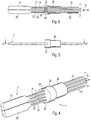
- Fig. 4 shows a second embodiment of the surgical instrument according to the invention with folded gripping parts in perspective view.
- Gripping parts 10 and 20 a guide sleeve 30 and their Cap section 32 shown.
- the gripping surfaces of the two gripping parts 10 and 20 smooth, i.e. unprofiled.
- the first, inner legs 11 and 21 and the second, outer legs 12 and 22 of the gripping parts 10 and 20 completely arranged within the guide sleeve, whereby pollution or pollution essentially prevented and exact guidance is ensured. Because it however it cannot be excluded that dirt like Liquids, blood or similar substances Capillary effect in the instrument, this is with a flushing channel provided for cleaning.
- the second legs 12 and 22 have projections 33 and 34, respectively on movement of the second legs 12 and 22 in Prevent longitudinally into the guide sleeve.
- the Projections 33 and 34 are in recesses provided therefor the cap portion 32 arranged so that also a Twisting the gripping parts 10 and 20 in the guide sleeve 30 is prevented.
- the projections also serve for mooring the second leg 12 and 22 on the guide sleeve 30.
- the projections 33 and 34 for example on the Guide sleeve 30 and / or cover cap 32 also glued or be clamped in the recesses of the cover cap 32.
- Fig. 5 shows a side view of that shown in Fig. 4 second embodiment of the surgical instrument.
- Fig. 6 shows a partial section along the line VI - VI of the in Fig. 5 illustrated embodiment.
- the Guide sleeve 30 consists of an insulating material, especially a plastic.
- the first, inner legs 11 and 21 of the two gripping parts 10 and 20 are longer than the second outer legs 12 and 22.
- the protrusions 33 and 34 of the second legs 12 and 22 of the two gripping parts 10 and 20 abut the guide sleeve 30 so that they are not in the guide sleeve can be moved into it.
- Fig. 7 represents the embodiment shown in Fig. 4 of the instrument with the gripping parts folded apart, the legs 13, 14, 23, 24 in the opening direction of the Gripping parts 10, 20 are pre-bent. So are at rest the gripping parts of the instrument unfolded.
- the two inner or first leg 11 and 21 moved in the direction of arrow 36. The movement creates a torque around the moored second leg 12 or 22, whereby the gripping parts 10 and 20 at the bending areas 13 and 14 or 23 and 24 of the Bend legs 11 and 12 or 21 and 22 so that the Fold gripping parts 10 and 20 together in gripping direction 37.
- the gripping surfaces 15 and 25 of the first are clearly visible or second gripping part 10 or 20. If at least one of the both gripping surfaces 15 or 25 is designed as a cutting edge, can the instrument 1 also for cutting tissue or as Scissors are used. 7 is the formation of the Gripping surface 25 indicated by a dash 26.
- FIG. 8 finally shows a side view of the one in FIG. 7 instrument shown and Fig. 9 is a section along the Line IX - IX of the instrument shown in Fig. 8.
Landscapes
- Health & Medical Sciences (AREA)
- Surgery (AREA)
- Life Sciences & Earth Sciences (AREA)
- Medical Informatics (AREA)
- Nuclear Medicine, Radiotherapy & Molecular Imaging (AREA)
- Engineering & Computer Science (AREA)
- Biomedical Technology (AREA)
- Heart & Thoracic Surgery (AREA)
- Ophthalmology & Optometry (AREA)
- Molecular Biology (AREA)
- Animal Behavior & Ethology (AREA)
- General Health & Medical Sciences (AREA)
- Public Health (AREA)
- Veterinary Medicine (AREA)
- Surgical Instruments (AREA)
- Endoscopes (AREA)
Abstract
Description
- 1
- chirurgisches Instrument
- 2
- Instrumentenspitze
- 3
- Handhabungsgriff
- 4
- Betätigungseinrichtung
- 10
- erstes Greifteil
- 11
- erster Schenkel
- 12
- zweiter Schenkel
- 13
- Biegebereich
- 14
- Biegebereich
- 15
- Greiffläche
- 20
- zweites Greifteil
- 21
- erster Schenkel
- 22
- zweiter Schenkel
- 23
- Biegebereich
- 24
- Biegebereich
- 25
- Greiffläche
- 26
- Schneide
- 30
- Führungshülse
- 31
- Abstandselement
- 32
- Kappenabschnitt
- 33
- Vorsprung
- 34
- Vorsprung
- 35
- Doppelpfeil
- 36
- Bewegungsrichtung der ersten Schenkel
- 37
- Greifrichtung
- 40
- Rohr
- 50
- Schlauch
- 51
- Schlauch
- 60
- Schraubenfeder
- 65
- HF-Stromgenerator
- 66
- erster Anschluß
- 67
- zweiter Anschluß
Claims (13)
- Chirurgisches Instrument (1), insbesondere Pinzette oder Zange für die minimalinvasive Chirurgie, umfassend: mindestens zwei Greifteile (10, 20), die zum Greifen in und entgegen einer Greifrichtung (37) zusammen bzw. auseinander klappbar sind,
dadurch gekennzeichnet, daß
mindestens ein Greifteil (10, 20) an einem Ende einen ersten und einen zweiten Schenkel (11, 12, 21, 22) mit jeweils einem Biegebereich (13, 14, 23, 24) aufweist, die in der Greifrichtung voneinander beabstandet sind, wobei mindestens der erste Schenkel (11, 21) des Greifteils (10, 20) innerhalb einer Führungshülse (30) angeordnet und in Längsrichtung der Führungshülse relativ zum zweiten Schenkel (12, 22) des Greifteils (10, 20) derart bewegbar ist, daß bei einer Relativbewegung der Schenkel zueinander in deren Längsrichtung das jeweilige Greifteil (10, 20) in Greifrichtung bewegbar ist. - Chirurgisches Instrument nach Anspruch 1,
dadurch gekennzeichnet, daß
der zweite Schenkel (12, 22) des Greifteils (10, 20) an der Führungshülse (30) festgemacht ist. - Chirurgisches Instrument nach Anspruch 1 oder 2,
dadurch gekennzeichnet, daß
jedes Greifteil (10, 20) mitsamt seinen Schenkeln (11, 12, 21, 22) einstückig aus einem leitfähigen, insbesondere metallenen Material hergestellt ist. - Chirurgisches Instrument nach einem der vorhergehenden Ansprüche,
dadurch gekennzeichnet, daß
der erste Schenkel (11, 21) jedes Greifteils (10, 20) länger als der zweite Schenkel (12, 22) ist. - Chirurgisches Instrument nach einem der vorhergehenden Ansprüche,
dadurch gekennzeichnet, daß
der zweite Schenkel (12, 22) jedes Greifteils (10, 20) insbesondere mit der Innenwand der Führungshülse (30) fest verbunden, insbesondere verklebt ist. - Chirurgisches Instrument nach einem der vorhergehenden Ansprüche,
dadurch gekennzeichnet, daß
die ersten Schenkel (11, 21) der Greifteile (10, 20) elektrisch voneinander isoliert sind. - Chirurgisches Instrument nach einem der vorhergehenden Ansprüche,
dadurch gekennzeichnet, daß
die Führungshülse (30) teilweise in ein Ende eines Schlauches oder insbesondere metallenen Rohres (40) eingeführt ist. - Chirurgisches Instrument nach Anspruch 7,
dadurch gekennzeichnet, daß
der Schlauch oder das Rohr (40) an dem der Führungshülse (30) gegenüberliegenden Ende mit einem Handhabungsgriff (3) zum Handhaben des Instrumentes (1) versehen ist. - Chirurgisches Instrument nach Anspruch 8,
dadurch gekennzeichnet, daß
die ersten Schenkel (11, 21) der Greifteile (10, 20) mit einer Betätigungseinrichtung (4) verbunden sind, die derart in dem Handhabungsgriff (3) gelagert ist, daß durch Einführen der Betätigungseinrichtung (4) in den Handhabungsgriff die ersten Schenkel in Längsrichtung der Führungshülse (30) und des Schlauches oder Rohres (40) vom Handhabungsgriff (3) weg bewegt werden, wodurch die Greifteile (10, 20) auseinander klappen und umgekehrt durch Herausziehen der Betätigungseinrichtung (4) aus dem Handhabungsgriff (3) die ersten Schenkel der Greifteile in Längsrichtung der Führungshülse und des Rohres zu der Betätigungseinrichtung (4) gezogen werden, wodurch die Greifteile zusammen klappen. - Chirurgisches Instrument nach Anspruch 9,
dadurch gekennzeichnet, daß
zwischen der Betätigungseinrichtung (4) und dem Handhabungsgriff (3) eine Spanneinrichtung (60) angeordnet ist, so daß die Betätigungseinrichtung ohne äußere Krafteinwirkung aus dem Handhabungsgriff gedrückt wird und die Greifteile zusammengeklappt sind. - Chirurgisches Instrument nach Anspruch 2,
dadurch gekennzeichnet, daß
der erste Schenkel (11, 21) durch eine Spanneinrichtung (60) in die Führungshülse (30) hineingezogen wird und ein Vorsprung (33, 34) am zweiten Schenkel (12, 22) vorgesehen ist, der ein Hineingleiten des Greifteils (10, 20) in die Führungshülse (30) verhindert. - Chirurgisches Instrument nach einem der vorhergehenden Ansprüche,
dadurch gekennzeichnet, daß
der erste Schenkel (11) eines ersten Greifteiles (10) mit einem ersten Anschluß (66) und der erste Schenkel (21) eines zweiten Greifteiles (12) mit einem zweiten Anschluß (67) eines HF-Stromgenerators (65) verbindbar sind. - Verwendung eines chirurgischen Instruments nach einem der vorhergehenden Ansprüche in einem Arbeitskanal eines Endoskops.
Applications Claiming Priority (4)
| Application Number | Priority Date | Filing Date | Title |
|---|---|---|---|
| DE10021724 | 2000-05-04 | ||
| DE10021724 | 2000-05-04 | ||
| DE10031773 | 2000-06-29 | ||
| DE10031773A DE10031773B4 (de) | 2000-05-04 | 2000-06-29 | Chirurgisches Greifinstrument, insbesondere Pinzette oder Zange |
Publications (3)
| Publication Number | Publication Date |
|---|---|
| EP1151723A2 true EP1151723A2 (de) | 2001-11-07 |
| EP1151723A3 EP1151723A3 (de) | 2002-01-23 |
| EP1151723B1 EP1151723B1 (de) | 2008-09-17 |
Family
ID=26005551
Family Applications (1)
| Application Number | Title | Priority Date | Filing Date |
|---|---|---|---|
| EP01110666A Expired - Lifetime EP1151723B1 (de) | 2000-05-04 | 2001-05-02 | Chirurgisches Instrument, insbesondere Pinzette oder Zange |
Country Status (3)
| Country | Link |
|---|---|
| US (1) | US6464703B2 (de) |
| EP (1) | EP1151723B1 (de) |
| JP (1) | JP4316821B2 (de) |
Cited By (13)
| Publication number | Priority date | Publication date | Assignee | Title |
|---|---|---|---|---|
| WO2011018153A1 (de) * | 2009-08-14 | 2011-02-17 | Erbe Elektromedizin Gmbh | Elektrochirurgisches instrument |
| WO2011018154A1 (de) * | 2009-08-14 | 2011-02-17 | Erbe Elektromedizin Gmbh | Elektrochirurgisches instrument |
| DE102010006201A1 (de) * | 2010-01-29 | 2011-08-04 | Richard Wolf GmbH, 75438 | Medizinisches Greifinstrument |
| EP3448297A4 (de) * | 2016-04-29 | 2019-12-04 | Intuitive Surgical Operations Inc. | Nachgiebige mechanismen mit umgekehrten werkzeugelementen |
| US10932867B2 (en) | 2013-08-15 | 2021-03-02 | Intuitive Surgical Operations, Inc. | Reusable surgical instrument with single-use tip and integrated tip cover |
| US11213287B2 (en) | 2018-11-15 | 2022-01-04 | Intuitive Surgical Operations, Inc. | Support apparatus for a medical retractor device |
| US11241246B2 (en) | 2010-02-08 | 2022-02-08 | Intuitive Surgical Operations, Inc. | Direct pull surgical gripper |
| US11272977B2 (en) | 2008-07-16 | 2022-03-15 | Intuitive Surgical Operations, Inc. | Medical instrument electrically energized using drive cables |
| US11291514B2 (en) | 2018-11-15 | 2022-04-05 | Intuitive Surgical Operations, Inc. | Medical devices having multiple blades and methods of use |
| US11432836B2 (en) | 2016-09-14 | 2022-09-06 | Intuitive Surgical Operations, Inc. | Joint assemblies with cross-axis flexural pivots |
| US11602336B2 (en) | 2016-12-19 | 2023-03-14 | Intuitive Surgical Operations, Inc. | Sample retrieval tool with compliant retention member |
| US11992287B2 (en) | 2018-04-10 | 2024-05-28 | Intuitive Surgical Operations, Inc. | Articulable medical devices having flexible wire routing |
| US12349960B2 (en) | 2015-05-21 | 2025-07-08 | Aesculap Ag | Electrosurgical coagulation instrument |
Families Citing this family (34)
| Publication number | Priority date | Publication date | Assignee | Title |
|---|---|---|---|---|
| EP1313401A4 (de) | 2000-08-30 | 2006-09-20 | Cerebral Vascular Applic Inc | Medizinisches instrument |
| US6755338B2 (en) | 2001-08-29 | 2004-06-29 | Cerebral Vascular Applications, Inc. | Medical instrument |
| EP2656777A3 (de) | 2004-08-31 | 2015-12-02 | Surgical Solutions LLC | Medizinische Vorrichtung mit Gelenkwelle |
| US20070049928A1 (en) * | 2005-02-08 | 2007-03-01 | Fleenor Richard P | Nickel titanium alloy electrosurgery instrument |
| DE102006023696B4 (de) | 2005-05-20 | 2019-10-17 | Kaneka Corporation | Hochfrequenz-Inzisionsinstrument für ein Endoskop |
| EP2572667B1 (de) * | 2005-09-26 | 2018-12-12 | Jichi Medical University | Instrument für die endoskopische Behandlung |
| AU2007257754A1 (en) | 2006-06-08 | 2007-12-21 | Bannerman, Brett | Medical device with articulating shaft |
| US10172669B2 (en) | 2009-10-09 | 2019-01-08 | Ethicon Llc | Surgical instrument comprising an energy trigger lockout |
| US20110213360A1 (en) * | 2010-02-26 | 2011-09-01 | Tyco Healthcare Group Lp | Tensioning Mechanism for Articulation Drive Cables |
| GB2480498A (en) | 2010-05-21 | 2011-11-23 | Ethicon Endo Surgery Inc | Medical device comprising RF circuitry |
| US8900232B2 (en) | 2011-05-06 | 2014-12-02 | Covidien Lp | Bifurcated shaft for surgical instrument |
| EP2744427B1 (de) * | 2011-08-15 | 2019-06-05 | Intuitive Surgical Operations, Inc. | Medizinisches instrument mit flexiblem spannbackenmechanismus |
| US9314292B2 (en) | 2011-10-24 | 2016-04-19 | Ethicon Endo-Surgery, Llc | Trigger lockout mechanism |
| JP6083076B2 (ja) * | 2012-04-04 | 2017-02-22 | 大平 猛 | モーションメモリ型細径手術ロボットシステム |
| US10159524B2 (en) | 2014-12-22 | 2018-12-25 | Ethicon Llc | High power battery powered RF amplifier topology |
| US10314638B2 (en) | 2015-04-07 | 2019-06-11 | Ethicon Llc | Articulating radio frequency (RF) tissue seal with articulating state sensing |
| US10959771B2 (en) | 2015-10-16 | 2021-03-30 | Ethicon Llc | Suction and irrigation sealing grasper |
| US10959806B2 (en) | 2015-12-30 | 2021-03-30 | Ethicon Llc | Energized medical device with reusable handle |
| US10987156B2 (en) | 2016-04-29 | 2021-04-27 | Ethicon Llc | Electrosurgical instrument with electrically conductive gap setting member and electrically insulative tissue engaging members |
| US10856934B2 (en) | 2016-04-29 | 2020-12-08 | Ethicon Llc | Electrosurgical instrument with electrically conductive gap setting and tissue engaging members |
| US10751117B2 (en) | 2016-09-23 | 2020-08-25 | Ethicon Llc | Electrosurgical instrument with fluid diverter |
| CN108078609B (zh) * | 2016-11-21 | 2020-09-11 | 张小彤 | 用于盲肠手术的夹持装置 |
| US11033325B2 (en) | 2017-02-16 | 2021-06-15 | Cilag Gmbh International | Electrosurgical instrument with telescoping suction port and debris cleaner |
| US10799284B2 (en) | 2017-03-15 | 2020-10-13 | Ethicon Llc | Electrosurgical instrument with textured jaws |
| US11497546B2 (en) | 2017-03-31 | 2022-11-15 | Cilag Gmbh International | Area ratios of patterned coatings on RF electrodes to reduce sticking |
| US10603117B2 (en) | 2017-06-28 | 2020-03-31 | Ethicon Llc | Articulation state detection mechanisms |
| US11484358B2 (en) | 2017-09-29 | 2022-11-01 | Cilag Gmbh International | Flexible electrosurgical instrument |
| US11033323B2 (en) | 2017-09-29 | 2021-06-15 | Cilag Gmbh International | Systems and methods for managing fluid and suction in electrosurgical systems |
| US11490951B2 (en) | 2017-09-29 | 2022-11-08 | Cilag Gmbh International | Saline contact with electrodes |
| US12471982B2 (en) | 2020-12-02 | 2025-11-18 | Cilag Gmbh International | Method for tissue treatment by surgical instrument |
| CN113598929B (zh) * | 2021-07-13 | 2023-08-15 | 象山县第一人民医院医疗健康集团 | 具有钳口结构的电胸外科手术器械 |
| US12508021B2 (en) | 2021-11-01 | 2025-12-30 | Cilag Gmbh International | Devices, systems, and methods for detecting tissue and foreign objects during a surgical operation |
| US11957342B2 (en) | 2021-11-01 | 2024-04-16 | Cilag Gmbh International | Devices, systems, and methods for detecting tissue and foreign objects during a surgical operation |
| US12521138B2 (en) * | 2022-04-04 | 2026-01-13 | Covidien Lp | Surgical tissue grasper including a compliant jaw assembly |
Family Cites Families (12)
| Publication number | Priority date | Publication date | Assignee | Title |
|---|---|---|---|---|
| US4005714A (en) * | 1975-05-03 | 1977-02-01 | Richard Wolf Gmbh | Bipolar coagulation forceps |
| US5172700A (en) | 1989-01-31 | 1992-12-22 | C. R. Bard, Inc. | Disposable biopsy forceps |
| DE3917328A1 (de) | 1989-05-27 | 1990-11-29 | Wolf Gmbh Richard | Bipolares koagulationsinstrument |
| DE4032471C2 (de) | 1990-10-12 | 1997-02-06 | Delma Elektro Med App | Elektrochirurgische Vorrichtung |
| US5222973A (en) * | 1992-03-09 | 1993-06-29 | Sharpe Endosurgical Corporation | Endoscopic grasping tool surgical instrument |
| US5807393A (en) * | 1992-12-22 | 1998-09-15 | Ethicon Endo-Surgery, Inc. | Surgical tissue treating device with locking mechanism |
| DE19537320C2 (de) | 1995-10-06 | 2001-05-31 | Deutsch Zentr Luft & Raumfahrt | Greifvorrichtung für einen Einsatz vorzugsweise in der minimal invasiven Chirurgie und Vorrichtung zum Betätigen einer am distalen Ende eines Einführungsrohrs vorgesehenen Greifvorrichtung |
| DE19700605B4 (de) * | 1997-01-10 | 2007-03-29 | Günter Bissinger Medizintechnik GmbH | Instrument, insbesondere für die endoskopische Chirurgie |
| US5961514A (en) * | 1997-05-14 | 1999-10-05 | Ethicon Endo-Surger, Inc. | Cordless electrosurgical instrument |
| DE19731884C1 (de) * | 1997-07-24 | 1999-04-22 | Wolf Gmbh Richard | Medizinisches Instrument |
| US6273887B1 (en) * | 1998-01-23 | 2001-08-14 | Olympus Optical Co., Ltd. | High-frequency treatment tool |
| DE19858512C1 (de) * | 1998-12-18 | 2000-05-25 | Storz Karl Gmbh & Co Kg | Bipolares medizinisches Instrument |
-
2001
- 2001-05-01 JP JP2001134000A patent/JP4316821B2/ja not_active Expired - Fee Related
- 2001-05-02 US US09/847,568 patent/US6464703B2/en not_active Expired - Lifetime
- 2001-05-02 EP EP01110666A patent/EP1151723B1/de not_active Expired - Lifetime
Cited By (26)
| Publication number | Priority date | Publication date | Assignee | Title |
|---|---|---|---|---|
| US11272977B2 (en) | 2008-07-16 | 2022-03-15 | Intuitive Surgical Operations, Inc. | Medical instrument electrically energized using drive cables |
| US12262938B2 (en) | 2008-07-16 | 2025-04-01 | Intuitive Surgical Operations, Inc. | Medical instrument electrically energized using drive cables |
| US11666374B2 (en) | 2008-07-16 | 2023-06-06 | Intuitive Surgical Operations, Inc. | Medical instrument with jaw with friction-coupled drive cable |
| US11357566B2 (en) | 2008-07-16 | 2022-06-14 | Intuitive Surgical Operations, Inc. | Medical instrument electrically energized using drive cables |
| WO2011018154A1 (de) * | 2009-08-14 | 2011-02-17 | Erbe Elektromedizin Gmbh | Elektrochirurgisches instrument |
| US8915913B2 (en) | 2009-08-14 | 2014-12-23 | Erbe Elektromedizin Gmbh | Electrosurgical instrument |
| WO2011018153A1 (de) * | 2009-08-14 | 2011-02-17 | Erbe Elektromedizin Gmbh | Elektrochirurgisches instrument |
| DE102010006201A1 (de) * | 2010-01-29 | 2011-08-04 | Richard Wolf GmbH, 75438 | Medizinisches Greifinstrument |
| DE102010006201B4 (de) * | 2010-01-29 | 2012-04-19 | Richard Wolf Gmbh | Medizinisches Greifinstrument |
| US12137926B2 (en) | 2010-02-08 | 2024-11-12 | Intuitive Surgical Operations, Inc. | Direct pull surgical gripper |
| US11241246B2 (en) | 2010-02-08 | 2022-02-08 | Intuitive Surgical Operations, Inc. | Direct pull surgical gripper |
| US10932867B2 (en) | 2013-08-15 | 2021-03-02 | Intuitive Surgical Operations, Inc. | Reusable surgical instrument with single-use tip and integrated tip cover |
| US12186038B2 (en) | 2013-08-15 | 2025-01-07 | Intuitive Surgical Operations, Inc. | Reusable surgical instrument with single-use tip and integrated tip cover |
| US12349960B2 (en) | 2015-05-21 | 2025-07-08 | Aesculap Ag | Electrosurgical coagulation instrument |
| EP3448297A4 (de) * | 2016-04-29 | 2019-12-04 | Intuitive Surgical Operations Inc. | Nachgiebige mechanismen mit umgekehrten werkzeugelementen |
| US11123145B2 (en) | 2016-04-29 | 2021-09-21 | Intuitive Surgical Operations, Inc. | Compliant mechanisms having inverted tool members |
| US12186047B2 (en) | 2016-04-29 | 2025-01-07 | Intuitive Surgical Operations, Inc. | Compliant mechanisms having inverted tool members |
| US12042164B2 (en) | 2016-09-14 | 2024-07-23 | Intuitive Surgical Operations, Inc. | Joint assemblies with cross-axis flexural pivots |
| US11432836B2 (en) | 2016-09-14 | 2022-09-06 | Intuitive Surgical Operations, Inc. | Joint assemblies with cross-axis flexural pivots |
| US12527593B2 (en) | 2016-09-14 | 2026-01-20 | Intuitive Surgical Operations, Inc. | Joint assemblies with cross-axis flexural pivots |
| US11602336B2 (en) | 2016-12-19 | 2023-03-14 | Intuitive Surgical Operations, Inc. | Sample retrieval tool with compliant retention member |
| US11992287B2 (en) | 2018-04-10 | 2024-05-28 | Intuitive Surgical Operations, Inc. | Articulable medical devices having flexible wire routing |
| US12201391B2 (en) | 2018-11-15 | 2025-01-21 | Intuitive Surgical Operations, Inc. | Medical devices having multiple blades and methods of use |
| US11213287B2 (en) | 2018-11-15 | 2022-01-04 | Intuitive Surgical Operations, Inc. | Support apparatus for a medical retractor device |
| US12285161B2 (en) | 2018-11-15 | 2025-04-29 | Intuitive Surgical Operations, Inc. | Support apparatus for a medical retractor device |
| US11291514B2 (en) | 2018-11-15 | 2022-04-05 | Intuitive Surgical Operations, Inc. | Medical devices having multiple blades and methods of use |
Also Published As
| Publication number | Publication date |
|---|---|
| JP4316821B2 (ja) | 2009-08-19 |
| US20010041893A1 (en) | 2001-11-15 |
| EP1151723B1 (de) | 2008-09-17 |
| EP1151723A3 (de) | 2002-01-23 |
| JP2002095671A (ja) | 2002-04-02 |
| US6464703B2 (en) | 2002-10-15 |
Similar Documents
| Publication | Publication Date | Title |
|---|---|---|
| DE10031773B4 (de) | Chirurgisches Greifinstrument, insbesondere Pinzette oder Zange | |
| EP1151723B1 (de) | Chirurgisches Instrument, insbesondere Pinzette oder Zange | |
| EP2077785B1 (de) | Rohrschaftinstrument | |
| WO2011018154A1 (de) | Elektrochirurgisches instrument | |
| EP1211995B1 (de) | Bipolares medizinisches instrument | |
| DE60023104T2 (de) | Polypektomieinstrument mit schlinge | |
| EP1052945B1 (de) | Medizinisches rohrschaftinstrument | |
| EP1055397A1 (de) | Medizinisches Instrument zum Präparieren von Gewebe | |
| WO2001054604A1 (de) | Bipolares fassinstrument | |
| DE102006047204A1 (de) | Rohrschaftinstrument | |
| DE102011079494A1 (de) | Elektrochirurgisches Greifinstrument | |
| DE202008001675U1 (de) | Zerlegbares chirurgisches Instrument | |
| DE102009037046A1 (de) | Rohrförmiger Schaft eines chirurgischen Instruments sowie chirurgisches Instrument | |
| WO2015110323A1 (de) | Chirurgischer handgriff für ein rohrschaftwerkzeug | |
| DE102009037613A1 (de) | Elektrochirurgisches Instrument | |
| EP2653123A1 (de) | Werkzeug für ein medizinisches Instrument | |
| EP3578118B1 (de) | Chirurgisches instrument | |
| DE102021109175B4 (de) | Elektrodeninstrument, chirurgisches Handgerät und deren Herstellungsverfahren | |
| DE19915062C1 (de) | Chirurgisches Instrument | |
| EP3300675B1 (de) | Komponente für ein medizinisches instrument und medizinisches instrument | |
| DE102008022332B4 (de) | Medizinisches Instrument zur Dilatation der Nasennebenhöhlen | |
| DE202007006619U1 (de) | Medizinisches Instrument | |
| EP3895644A1 (de) | Chirurgisches instrument | |
| EP1582157B1 (de) | Medizinisches Instrument zum Präparieren von Gewebe | |
| EP2298204A1 (de) | Medizinisches Instrument für die bipolare Elektrochirurgie |
Legal Events
| Date | Code | Title | Description |
|---|---|---|---|
| PUAI | Public reference made under article 153(3) epc to a published international application that has entered the european phase |
Free format text: ORIGINAL CODE: 0009012 |
|
| AK | Designated contracting states |
Kind code of ref document: A2 Designated state(s): AT BE CH CY DE DK ES FI FR GB GR IE IT LI LU MC NL PT SE TR Kind code of ref document: A2 Designated state(s): DE FR GB |
|
| AX | Request for extension of the european patent |
Free format text: AL;LT;LV;MK;RO;SI |
|
| PUAL | Search report despatched |
Free format text: ORIGINAL CODE: 0009013 |
|
| AK | Designated contracting states |
Kind code of ref document: A3 Designated state(s): AT BE CH CY DE DK ES FI FR GB GR IE IT LI LU MC NL PT SE TR |
|
| AX | Request for extension of the european patent |
Free format text: AL;LT;LV;MK;RO;SI |
|
| RIC1 | Information provided on ipc code assigned before grant |
Free format text: 7A 61B 17/28 A, 7A 61B 18/14 B |
|
| 17P | Request for examination filed |
Effective date: 20020709 |
|
| AKX | Designation fees paid |
Free format text: DE FR GB |
|
| GRAP | Despatch of communication of intention to grant a patent |
Free format text: ORIGINAL CODE: EPIDOSNIGR1 |
|
| GRAS | Grant fee paid |
Free format text: ORIGINAL CODE: EPIDOSNIGR3 |
|
| GRAA | (expected) grant |
Free format text: ORIGINAL CODE: 0009210 |
|
| AK | Designated contracting states |
Kind code of ref document: B1 Designated state(s): DE FR GB |
|
| REG | Reference to a national code |
Ref country code: GB Ref legal event code: FG4D Free format text: NOT ENGLISH |
|
| REF | Corresponds to: |
Ref document number: 50114325 Country of ref document: DE Date of ref document: 20081030 Kind code of ref document: P |
|
| PLBE | No opposition filed within time limit |
Free format text: ORIGINAL CODE: 0009261 |
|
| STAA | Information on the status of an ep patent application or granted ep patent |
Free format text: STATUS: NO OPPOSITION FILED WITHIN TIME LIMIT |
|
| 26N | No opposition filed |
Effective date: 20090618 |
|
| REG | Reference to a national code |
Ref country code: FR Ref legal event code: PLFP Year of fee payment: 16 |
|
| REG | Reference to a national code |
Ref country code: FR Ref legal event code: PLFP Year of fee payment: 17 |
|
| REG | Reference to a national code |
Ref country code: FR Ref legal event code: PLFP Year of fee payment: 18 |
|
| PGFP | Annual fee paid to national office [announced via postgrant information from national office to epo] |
Ref country code: FR Payment date: 20180529 Year of fee payment: 18 |
|
| PGFP | Annual fee paid to national office [announced via postgrant information from national office to epo] |
Ref country code: GB Payment date: 20180405 Year of fee payment: 18 Ref country code: DE Payment date: 20180731 Year of fee payment: 18 |
|
| REG | Reference to a national code |
Ref country code: DE Ref legal event code: R119 Ref document number: 50114325 Country of ref document: DE |
|
| GBPC | Gb: european patent ceased through non-payment of renewal fee |
Effective date: 20190502 |
|
| PG25 | Lapsed in a contracting state [announced via postgrant information from national office to epo] |
Ref country code: DE Free format text: LAPSE BECAUSE OF NON-PAYMENT OF DUE FEES Effective date: 20191203 Ref country code: GB Free format text: LAPSE BECAUSE OF NON-PAYMENT OF DUE FEES Effective date: 20190502 |
|
| PG25 | Lapsed in a contracting state [announced via postgrant information from national office to epo] |
Ref country code: FR Free format text: LAPSE BECAUSE OF NON-PAYMENT OF DUE FEES Effective date: 20190531 |