EP1150780B1 - Verfahren und vorrichtung zur kontrolle des profils für direkte beschichtung - Google Patents
Verfahren und vorrichtung zur kontrolle des profils für direkte beschichtung Download PDFInfo
- Publication number
- EP1150780B1 EP1150780B1 EP00903444A EP00903444A EP1150780B1 EP 1150780 B1 EP1150780 B1 EP 1150780B1 EP 00903444 A EP00903444 A EP 00903444A EP 00903444 A EP00903444 A EP 00903444A EP 1150780 B1 EP1150780 B1 EP 1150780B1
- Authority
- EP
- European Patent Office
- Prior art keywords
- coating
- coating head
- head
- distortions
- strip article
- Prior art date
- Legal status (The legal status is an assumption and is not a legal conclusion. Google has not performed a legal analysis and makes no representation as to the accuracy of the status listed.)
- Expired - Lifetime
Links
Images


Classifications
-
- B—PERFORMING OPERATIONS; TRANSPORTING
- B05—SPRAYING OR ATOMISING IN GENERAL; APPLYING FLUENT MATERIALS TO SURFACES, IN GENERAL
- B05C—APPARATUS FOR APPLYING FLUENT MATERIALS TO SURFACES, IN GENERAL
- B05C5/00—Apparatus in which liquid or other fluent material is projected, poured or allowed to flow on to the surface of the work
- B05C5/02—Apparatus in which liquid or other fluent material is projected, poured or allowed to flow on to the surface of the work the liquid or other fluent material being discharged through an outlet orifice by pressure, e.g. from an outlet device in contact or almost in contact, with the work
- B05C5/0295—Floating coating heads or nozzles
-
- B—PERFORMING OPERATIONS; TRANSPORTING
- B05—SPRAYING OR ATOMISING IN GENERAL; APPLYING FLUENT MATERIALS TO SURFACES, IN GENERAL
- B05C—APPARATUS FOR APPLYING FLUENT MATERIALS TO SURFACES, IN GENERAL
- B05C5/00—Apparatus in which liquid or other fluent material is projected, poured or allowed to flow on to the surface of the work
- B05C5/001—Apparatus in which liquid or other fluent material is projected, poured or allowed to flow on to the surface of the work incorporating means for heating or cooling the liquid or other fluent material
-
- B—PERFORMING OPERATIONS; TRANSPORTING
- B05—SPRAYING OR ATOMISING IN GENERAL; APPLYING FLUENT MATERIALS TO SURFACES, IN GENERAL
- B05C—APPARATUS FOR APPLYING FLUENT MATERIALS TO SURFACES, IN GENERAL
- B05C5/00—Apparatus in which liquid or other fluent material is projected, poured or allowed to flow on to the surface of the work
- B05C5/02—Apparatus in which liquid or other fluent material is projected, poured or allowed to flow on to the surface of the work the liquid or other fluent material being discharged through an outlet orifice by pressure, e.g. from an outlet device in contact or almost in contact, with the work
- B05C5/0254—Coating heads with slot-shaped outlet
Definitions
- This invention relates to the coating of elongated strip articles, such as metal sheet or strip. More particularly, the invention relates to such coating achieved by the utilization of direct coating apparatus having floating extrusion heads.
- the slot allows coating material to be extruded into the gap between the coating head and the adjacent surface of the strip article.
- an extended, generally flat, sloping surface (usually referred to as a "land") is provided on the downstream side of the slot of each coating head.
- This land slopes with a predetermined angle inwardly towards the surface to be coated in the direction of advance of the strip article.
- the space into which the coating material is extruded consequently narrows in the direction of strip advance, and this causes the coating material to be compressed in the gap and consequently to exert an outward force on the land as the material is squeezed and metered to the desired coating film thickness.
- At least one of the coating heads is movable generally at right angles to the strip article and is urged by some form of pushing arrangement towards the strip.
- the force generated by the coating material on the land balances the force provided by the pushing arrangement pressing the coating head towards the strip article, causing the coating head to float on the newly forming film of coating material without actually touching the strip article itself.
- This floating effect allows a constant thickness of coating material to be applied to the strip surfaces regardless of any non-planar condition of those surfaces, since the floating coating heads follow any contours or irregularities of the strip thickness as the strip article is advanced through the coater apparatus.
- Direct coaters of this kind can be used for applying various kinds of solvent-borne coatings (e.g. paints, lacquers, enamels, etc.).
- solvent-borne coatings e.g. paints, lacquers, enamels, etc.
- US patent 5,622,562 to Innes et al. which issued on April 22, 1997 and also is assigned to the same assignee as the present application, describes a similar coating apparatus and method for coating strip articles with layers of molten polymer material.
- the coating dies are usually quite wide so that they may extend completely across the width of a sheet article to be coated. Die lengths of 76.2 cm (30 inches) or more are usual.
- thin coatings e.g. coatings of 10 microns ( ⁇ m) or less
- the profile of the coating face of each coating die must closely follow the profile of the adjacent part of the surface to be coated (viewed in the direction transverse to the direction of advance of the sheet article). If this is not the case, the thickness of the coating applied to the surface will vary to an extent that will be noticeable in the finished coated article.
- two polymer coating materials commonly employed for this type of coating are polypropylene and polyethylene, and these require coating temperatures in the range of 200 - 300°C.
- temperature differentials within the coating head in the range of 50 - 100°C are usual, and this may produce considerable distortion of the die over its width.
- the coating heads are supported by unheated metal support plates at the rear surface of the coating heads opposite to the coating faces.
- the rear portions of the coating heads are therefore usually cooler than the coating face, so the coating face becomes "crowned" over the width of the coating head, i.e. bent in a convex bow so that the center of the coating face approaches the surface to be coated more closely than the ends of the coating face.
- the distortion from the desired flat profile may amount to 250 ⁇ m (0.01 inch). Obviously, this is completely unacceptable for coatings intended to be a uniform 10 ⁇ m in thickness.
- the coating heads are pushed towards the surface to be coated by a pushing force, it is possible to modify the pushing force over the length of each die to compensate for the distortion produced by temperature differentials.
- relatively high loads are required and this necessitates a strong supporting frame, thus complicating the coating apparatus and requiring increased construction costs.
- the totals of such loads may be inconsistent with that required to obtain a desired film thickness. Indeed, it is possible to encounter distortions beyond the range of those correctable by adjustment of the load profile. This is particularly frequent in the case of two-sided direct coaters where the loading device on one die must correct for the sum of the distortions in both opposed dies.
- An object of the present invention is to provide a process and apparatus for coating a sheet article with a coating film of uniform thickness across the width of the sheet article.
- Another object of the present invention is to compensate for distortions of the coating profiles of coater heads used in direct coating apparatus.
- Another object of the invention is to prevent irregularities in thin coatings of coating materials that are applied in heated molten form by direct coater apparatus.
- a coating apparatus including at least one floating coating head having a coating profile that becomes distorted by heat during use, the improvement which comprises providing heaters in or adjacent to specific regions of said at least one coating head to equalize temperatures throughout said coating head to substantially prevent or correct distortion of said coating profile.
- a coating apparatus for two-sided coating of an elongated strip article having coating heads in register on opposite sides of the strip article for applying a coating of material, each coating head including a coating surface having a coating profile, and at least one of said heads floating on a layer of applied coating material under a pressing force directed towards the strip article, wherein one of said coating heads is provided with means for varying heat flux to or from said coating head to modify the coating profile of said one coating head, thus enabling the coating profile of the one head to conform to the coating profile of the coating head on an opposite side of the strip article.
- a process of coating a strip article with a film of coating material by passing the strip article through a coating apparatus having at least one floating coating head provided with a coating face, extending from one end of the coating head to an opposite end, facing and extending laterally across a surface of the strip article to be coated, said coating face including an elongated slot and an extended surface forming a land positioned downstream of the slot and arranged at an effective land angle with respect to the surface to be coated causing said land to slope inwardly towards said surface in a direction of movement of said strip article through said apparatus, and extruding a liquid coating material from the slot onto a surface of the strip article to be coated to be engaged by the land to meter said coating material to a desired coating thickness and to create a force on said at least one coating head that balances a pressing force urging the coating head towards the surface to be coated, wherein said coating face of said at least one coating head has a preferred coating profile between said one and said opposite ends of the coating
- a coating apparatus for coating a strip article with a film of coating material, comprising: a strip article feed for advancing a strip article through said apparatus along a strip article path; at least one floating coating head provided with a coating face, extending from one end of the coating head to an opposite end, facing and extending laterally across a surface of the strip article to be coated, said coating face including an elongated slot and an extended surface forming a land positioned downstream of the slot and arranged at an effective land angle with respect to the surface to be coated causing said land to slope inwardly towards said surface in a direction of movement of said strip article through said apparatus; a material feed for supplying liquid coating material to said coating head; and force applying means for urging said coating head towards said strip article, whereby said strip article advanced through the apparatus by the strip article feed is coated with coating material exuded from said elongated slot of the coating head and is engaged by said land to meter said coating material to a metered coating thickness, and force generated on said
- a coating head for a direct coating apparatus employing at least one floating coating head for coating a strip article with a film of coating material, said coating head comprising: a coating face, extending from one end of the coating head to an opposite end, said coating face including an elongated slot and an extended surface forming an angled land positioned adjacent to the slot; and an inlet for coating material to the coating head for delivery to the slot; wherein said coating face has a preferred coating profile formed between said one and said opposite ends of the coating head; and wherein said coating head is provided with one or more heat flux modifying devices for modifying heat flux to or from selected parts of said coating head effective to prevent or correct substantial distortions of said preferred coating profile during coating of said strip article.
- coating profile in the context of this invention means the profile of the coating surface that affects the ultimate thickness of the metered coating layer. This is usually the profile of the downstream edge of the coating land in elevational view as the strip advances towards the viewer.
- the term "modifying" the heat flux may mean supplying heat to the coating head of the coater apparatus, or reducing heat flow from the coater head.
- the distortions from the preferred profile are generally substantially prevented by providing heat to specific regions of the coating head to equalize temperatures throughout the coating head.
- the heat flux is generally provided to a rear wall of the coating head opposite to the coating face, more heat being provided close to the lateral ends of the coating head than to a region of the rear wall located centrally between its lateral ends.
- the coating head may be supported by a backing support plate, and distortions may be substantially prevented by providing heat to specific regions of the backing support plate to equalize temperature throughout the coating head.
- the backing support plate has lateral ends adjacent to lateral ends of said coating head, and more heat is usually provided to regions of the backing support plate close to the lateral ends thereof than to a region of the backing support plate located centrally between the lateral ends thereof.
- the heat may be provided by locating electrical heaters in specific regions of the coater head or backing plate, and operating the heaters when required to substantially prevent distortions.
- distortions of the coating profile may be measured and, when the distortions exceed a predetermined amount, heat flux may be modified to reduce such distortions.
- the distortions may be measured directly by measuring positions of points on the coating surface, or indirectly by measuring temperature differentials at points on said coating head.
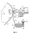
- Fig. 1 is an illustration of a known apparatus intended for single-sided coating of a metal strip article (made, for example, of aluminum or aluminum alloy) with a molten polymer (for example, molten polypropylene or polyethylene), and is of the type disclosed in the US patent 5,622,562 (the disclosure of which is specifically incorporated herein by reference).
- a molten polymer for example, molten polypropylene or polyethylene
- This apparatus is briefly described below so that the present invention, and its preferred forms, may be better understood. The description of this apparatus should not, of course, be taken as an indication that the invention may be employed with only this kind of apparatus.
- the apparatus shown in FIG. 1 includes a coating head 12 that is heated (by integral heaters, not shown) to ensure uniform temperature and viscosity of the extruded polymer, and has interior passages that are streamlined for polymer flow to improve flow uniformity and to avoid “dead zones” that might cause degradation of the heated polymer.
- the coating head 12 (shown partially in cross-section) applies a thin film of polymer coating material 13 to a metal strip article 14 passing around a heated backup drum 16 rotating in the direction of the arrow A.
- the coating head 12 extends laterally across the entire transverse width of the strip at a locality, in the path of the strip advance, at which the strip is held firmly against the outer surface of the backup drum 16.
- a system of mutually spaced air cylinders 17 acts as force-applying means and urges the coating head 12 towards the strip 14 at a number of locations along the width of the strip to apply a suitable load to the coating material 13 as it is fed onto the strip surface through an elongated coating slot 15.
- the force applying means may alternatively employ, for example, hydraulic cylinders, springs or-weights instead of pneumatic (air) cylinders.
- the coating head 12 is fed with heated molten polymer coating material from a screw extruder 18 (shown in cross-section) via at least one heated high pressure hose 19.
- the hose 19 may be a conventional flexible hose first wrapped with an electrical heating element (wire) and then wrapped with flexible insulation.
- Other apparatus for providing molten coating material under pressure may, of course, be employed.
- the polymer material 13 can be kept in a molten condition within the required viscosity range until applied as a coating to the strip 14. It will be understood that the surface of the strip 14 may bear a previously applied undercoat or primer coat of paint, and the opposite surface of the strip may also be precoated.
- the coating head 12 facing the surface to be coated has a flat or concavely curved coating face 32 arranged at an angle (normally in the range of 0.1 to 5°, or more preferably 0.5 to 1°) to the surface of the moving strip 14 (in side view, as in Fig. 1) forming a gap 34 converging in the direction of the strip advance.
- the part of the coating surface downstream of the coating slot 15 forms an extended surface or land 32a that contacts the polymer melt as it is applied to the strip 14 and receives a hydrodynamic force from the melt as it moves through the converging coating gap 34.
- the slot 15 is orientated with its long dimension transverse to the direction of advance of the strip 14; very preferably, the long dimension of the slot is perpendicular to the direction of strip advance and parallel to the axis of rotation of the drum 16.
- heated molten polymer is continuously supplied under pressure by the screw extruder 18 to the internal melt cavity 40 and thence to the slot 15 at a rate sufficient to keep the cavity 40 entirely filled and to force the polymer from the slot 15 under pressure so that the slot, as well, is continuously entirely filled with polymer under pressure.
- the coating head 12 may form part of a rigid metal block 30, more usually the coating head is provided as a separate unit bolted to a backing support plate (not shown in Fig. 1).
- the backing support plate may then be acted upon by air cylinders 17. This allows the coating head to be removed from the apparatus in a simple and convenient way with minimal disruption of other equipment, e.g. the air cylinders (i.e. by allowing the coating head to be unbolted from the backing plate and removed from the remaining apparatus for cleaning or replacement).
- a further preferred modification is that the coating head is shaped such that the land 32a projects outwardly of the main part of the coating head 12 in the direction of strip advance, and only the land part of the coating head is acted upon by the load cylinders. Since the land portion effects the metering, whereas the remainder of the coating head merely feeds the molten material into the converging coating gap, the land portion is the critical part of the apparatus for receiving the load.
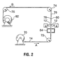
- FIG. 2 An example of an apparatus suitable for two-sided coating is shown schematically in FIG. 2.
- a metal strip 14 to be coated is continuously advanced, in a direction longitudinally parallel to its long dimension, from a coil 70 along a path represented by arrows A and B extending successively around mutually spaced guide rollers 72, 74 and 75 rotatably supported (by structures not shown) in axially fixed positions.
- the rollers 72 and 74 cooperatively define a rectilinear portion 76 of the path, in which portion the major surfaces of the advancing strip are substantially planar.
- polymer is applied to both major surfaces 78, 80 of the strip from two coating devices 12, 12' (disposed in register with each other, and respectively facing the two major surfaces of the strip article) to establish on each of the strip surfaces a continuous layer or coating of the polymer.
- the coating devices 12 and 12' may each include floating coating heads of the same type as the coating device 12 of the embodiment shown in FIG. 1, and may each be provided with heated polymer melt in the same fashion as previously described.
- one of the coating devices 12 and 12' be of the floating coating head type, and the other may include a fixed coating head.
- the strip article When the strip article is appropriately thin and flexible (which it normally is for strip articles coated with this kind of equipment), the strip article itself may move slightly towards or away from the fixed coating head, so forces on each side of the strip article tend to equalize.
- the floating coating head floats on the extruded polymer melt.
- the strip article On the other side of the strip, the strip article itself floats on the extruded polymer melt, so that a uniform coating film thickness is obtained on both sides.
- either or both of the strip major surfaces may bear a previously applied undercoat or primer coat of paint.
- the coated strip After passing roll 75, the coated strip is coiled again, e.g. on a driven rewind reel 82 which constitutes the means for advancing the strip through the coating line.
- the strip 14 may, if necessary, be advanced through a heating oven 84 immediately upstream of the positions of the coating devices 12, 12', to provide pre-heating of the strip prior to the application of the polymer coating in order to maintain suitable viscosity of the coating at the coating heads.
- the apparatus of Figs. 1 and 2 is conventional, but when used to apply very thin coating films (e.g. 1 to 25 ⁇ m, and ideally less than 10 ⁇ m, e.g. 2 to 7 ⁇ m) to a strip article, may produce uneven coating due to distortion of the coating head across its width (its long dimension transverse to the direction of advancement of the strip article) as a result of the heating required to keep the polymer molten.
- very thin coating films e.g. 1 to 25 ⁇ m, and ideally less than 10 ⁇ m, e.g. 2 to 7 ⁇ m
- Figs. 3A and 3B are simplified elevational views of a coating head 12 and supporting plate 130 of the type that may be used in the apparatus of Figs. 1 and 2.
- the coating head has a coating face 32 and an opposite face 132 supported by the supporting plate 130.
- the upper edge of the coating head 12 as shown forms the "coating profile" 135, i.e. the shape of the coating face 32 of the coating head extending from one end 136 of the coating head to an opposite end 137.
- Fig. 3A represents the coating head in the cold condition before coating commences.
- the desired coating profile 135 is flat since the coating head is intended for coating a flat surface of a sheet article.
- the profile becomes convex or "crowned" at the center, as shown in Fig. 3B.
- the coating face 32 tends to be hotter than the opposite face 132 due to the flow of heat from the coating head to the unheated support plate 130, and due to loss of heat at the exposed ends 136, 137 of the coating head that are not in direct contact with the polymer melt and that are exposed to the atmosphere.
- selected parts of the coating head are subjected to variations of heat flux. That is to say, the temperature of those selected parts may be raised to equalize the temperature throughout the coating head, or the normal heat loss may be prevented or minimized from selected parts of the coating head by selected application of heat insulating material. Again, the intention is to equalize the temperature distribution throughout the coating head so that the distortion of the coating profile caused by heat differences is avoided.
- Fig. 4A is an enlarged view of a coating head similar to the views of Figs. 3A and 3B, but showing one preferred form of an apparatus according to the invention. It will be seen that the coating head 12 has been drilled parallel to the opposite surface 132 with a number of blind holes 140 that pass almost completely through rear wall 141 of the coating head. These holes do not, of course, penetrate the hollow interior 40 of the coating head, so there is no loss of coating material through these holes. It will be noticed that the holes are not equally spaced from each other, but instead the separation of adjacent holes decreases with distance from the center 142 of the coating head.
- Electrical heating elements 144 are positioned in the holes and are connected to an electrical supply 143 via a controller 146. These electrical heating elements are all preferably of the same maximum wattage, but their heat output may be controlled individually or collectively by the controller 146. The intention is that, as coating commences and progresses, the heating elements 144 are actuated to heat the opposite surface of the coating head 132 so that its temperature remains similar or identical to that of the coating face 32. As the holes 140 are more closely spaced towards the ends 136, 137 of the coating head, more electrical elements are provided per linear distance unit, so more heat is provided to compensate for the greater heat loss in these regions. In effect, the rear wall 141 is divided into several notional regions, i.e.
- the elements may be turned to their maximum heating value as soon as coating preparations commence, or may be ramped up to their maximum value over the first few minutes of coating to mimic temperature rises of the coating face of the coating face of the coating head.
- a greater heat flux to the rear portion of the coating head in the end regions may be achieved by providing more powerful heating elements closer to the ends than in the middle, or by reducing the power outputs of the central heating elements 144 compared to those near the ends.
- Fig. 4B shows an apparatus similar to that of Fig. 4A, except that the holes 140 and heating elements 144 are positioned in the backing support plate 130 rather than in the adjacent wall of the coating head 12.
- the arrangement allows the coating head 12 to be separated from the backing plate 130 without having to disconnect the circuitry to the heating elements 144 or without having to withdraw the heating elements from the drilled holes.
- it is often difficult to find suitable space for holes 140 in the coating head itself because of inadequate wall thickness, the presence of holes required for melt channels, thermocouples, heaters and the like, and the presence of adjacent equipment, etc.
- Fig. 5 shows a coating head similar to that of Figs. 4A and 4B (the holes 140, heating elements 144 and accompanying circuitry having been omitted for clarity), but including a feedback control mechanism for measuring either differences in temperature between the coating face and the opposite face, and providing changes of heat flux to compensate, or for measuring actual distortions of the coating profile, and again providing changes in heat flux to compensate.
- the coating head 12 is provided at one end with a pair of embedded temperature sensors 150, 151, e.g. thermocouples, one adjacent the coating face and the other opposite the opposite face. Signals from the temperature sensors are compared by comparator 154 and, when there is a detectable difference, a signal is sent to controller 146 to actuate the heating elements 144 or to increase the electrical power supplied thereto.
- a laser sensor 160 is positioned on a fixed, unheated part 161 of the apparatus and a laser beam 162 is projected towards the center of the coating profile 135 slightly beyond the coating face 32.
- the coating profile is flat (as desired)
- the beam is projected into the gap between the coating head 12 and the sheet article 14 and reflections of the beam are weak.
- the profile is becomes crowned, the beam strikes the edge of the coating head 12 and is reflected strongly.
- the sensor includes a detector for reflected laser light and when the a strong reflection is detected, a signal is sent to the controller 146 to actuate (or increase the power to) the electrical elements 144 (see Fig 4A).
- An alternative more direct laser technique of measuring changes in the coating profile involves identifying a suitable reference surface on the coating head and providing a laser range finder that measures the distance to the reference surface.
- the controller 146 or equivalent device may be under the control of a computer 165 programmed to provide different heating rates and heating profiles required for different coating application temperatures (e.g. when different coating materials are employed).
- the program for such a computer may be developed by observing different profile distortions in different conditions, and by observing the heating rates and patterns that reduce such distortions to acceptable levels, and then matching the heating rates and patterns to distortions expected in various operating conditions. This is an essentially empirical approach. Alternatively, distortions may be calculated using known expansion rates for metals used for coating heads and coating head geometries, and such calculations may be used to control the heating rates and patterns, as required.
- Fig. 6 shows an alternative apparatus in which, instead of heating the rear portion of the coating head by means of electrical heaters, the temperature of the coating head is kept substantially equal at the front and rear portions by providing a layer of a heat insulator 170 at the rear of the coating head.
- the insulating material also extends over the support plate 130 as shown, and is of increased thickness near the ends 136, 137 of the coating head, reflecting the greater potential for heat loss in these positions.
- the temperature profile of the rear portion of this coating head may be modified so that the coating profile of this head matches that of the other coating head.
- the temperature profile of one coating head is used to control the coating gap (between the two opposing coating faces) so that it approaches a constant value across the width of the strip article. It does not much matter if the coating profiles thus achieved deviate somewhat from planar because the strip article (if sufficiently flexible) will conform itself to the non-planar coating profile, allowing a film of coating material of uniform thickness to be applied to both sides.
- the fixed coating device is normally positioned below a horizontal run of the strip article, and the floating coating device is positioned above the run and is provided with the load control components and is substantially free floating within linear bearings. In this way, contact with a support structure is minimized and thermal distortion is minimized.
- the upper structure is thus relatively light in weight and the metering load is primarily supported by the piston rods of the air cylinders.
- the lower coating device is rigid and is solidly bolted to the support structure. Thus, the bottom coating head is where control of heat flux is more appropriate.
- the temperature modification equipment is preferably associated with the fixed coating head. This is because the fixed coating head is generally more accessible and simpler to modify.
- polymeric materials suitable for use in the apparatus of the invention are generally those having viscosities in the ranges of 1,000 to 2,000,000 CPS at 1 rad./sec according to ASTM D4440, more preferably 10,000 to 1,000,000 CPS, at temperatures between their melting points and their decomposition temperatures, i.e. normally at temperatures in the range of 150° to 350°C.
- suitable polymers include polyethylene (e.g. EPOLENETM C-17 or C-13 polyethylene wax; effective temperature range 150°-260°C), polyethylene terephthalate (e.g.
- VECODERTM EPPN effective temperature range 200°C-340°C.
- mixtures of ethylene acrylic acid copolymer and polybutylene e.g. PRIMACORTM 3400 - 75% PRIMACORTM and 25% SHELLTM PB 0300; effective temperature range 160°-310°C.
- the substrate strip article is, as noted above, usually a metal sheet made of aluminum or an aluminum alloy, e.g. intended for fin stock or can stock.
- the coaters could be used for coating a wide range of materials, including steel and paper, etc.
- the present invention may be used with slot coaters, such as the high solids Alcan® direct coater (ADC).
- ADC high solids Alcan® direct coater
- a coating device normally operating at ambient temperature may be provided with a support structure with back heaters capable of raising the temperature by up to approximately 20°C, if necessary. This modifies the shape of the coating head (to make the surface more concave).
- the invention is primarily intended for use with coating devices that become distorted due to differential temperature gradients, distortions may also be produced by machining tolerances which result in non-planar coating surfaces even in equipment intended to apply coatings at ambient or low temperatures.
- the invention may be used to correct for such distortions to create coating films of uniform thickness. In such cases, of course, care should be taken to ensure that any heating of the coating device does not adversely affect the coating material or coating process since some materials and processes are temperature sensitive.
Landscapes
- Coating Apparatus (AREA)
- Application Of Or Painting With Fluid Materials (AREA)
- Length Measuring Devices With Unspecified Measuring Means (AREA)
Claims (24)
- Ein Verfahren zum Beschichten eines Streifengegenstandes (14) mit einem Film aus Beschichtungsmaterial (13) durch Bewegen des Streifengegenstands durch eine Beschichtungsvorrichtung mit zumindest einem schwebenden Beschichtungskopf (12, 12'), der mit einer Beschichtungsfläche (32) versehen ist, die sich von einem lateralen Ende (136) des Beschichtungskopfes zu einem gegenüberliegenden lateralen Ende (137) erstreckt, und die sich in transversaler Richtung quer über eine Oberfläche des zu beschichtenden Streifengegenstands erstreckt und dieser gegenübersteht, wobei die Beschichtungsfläche einen länglichen Schlitz (15) und eine verlängerte Oberfläche (32a) umfasst, die ein Land bildet, das auf der stromabwärtigen Seite des Schlitzes positioniert ist und unter einem effektiven Landwinkel in Bezug auf die zu beschichtende Oberfläche angeordnet ist, was dazu führt, dass das Land sich nach innen zu der Oberfläche hin in einer Bewegungsrichtung des Streifengegenstands durch die Vorrichtung neigt, und durch Extrudieren eines flüssigen Beschichtungsmaterials (13) von dem Schlitz auf eine Oberfläche des zu beschichtenden Streifengegenstands (14), die mit dem Land in Eingriff tritt, um das Beschichtungsmaterial auf eine erwünschte Beschichtungsdicke zu dosieren, und um eine Kraft auf den zumindest einen Beschichtungskopf zu erzeugen, die eine Druckkraft ausgleicht, welche den Beschichtungskopf zur zu beschichtenden Oberfläche hin drängt, dadurch gekennzeichnet, dass die Beschichtungsfläche (32) des zumindest einen Beschichtungskopfes (12, 12') ein bevorzugtes Beschichtungsprofil zwischen dem einen lateralen Ende (136) und dem gegenüberliegenden lateralen Ende (137) des Beschichtungskopfes aufweist, und wobei Verzerrungen des bevorzugten Beschichtungsprofils während der Beschichtung des Streifengegenstands im wesentlichen verhindert oder korrigiert werden, indem der Wärmefluss zu oder von ausgewählten Abschnitten des Beschichtungskopfes modifiziert wird.
- Ein Verfahren nach Anspruch 1, dadurch gekennzeichnet, dass die Verzerrungen im wesentlichen dadurch verhindert werden, dass Wärme spezifischen Bereichen des zumindest einen Beschichtungskopfes (12, 12') zugeführt wird, um Temperaturen in dem zumindest einen Beschichtungskopf auszugleichen.
- Ein Verfahren nach Anspruch 2, dadurch gekennzeichnet, dass Wärme einer hinteren Wand des Beschichtungskopfes gegenüberliegend der Beschichtungsfläche zugeführt wird.
- Ein Verfahren nach Anspruch 3, dadurch gekennzeichnet, dass mehr Wärme Bereichen der hinteren Wand in der Nähe der lateralen Enden des Beschichtungskopfes zugeführt wird als einem Bereich der hinteren Wand, der sich mittig zwischen den lateralen Enden befindet.
- Ein Verfahren nach Anspruch 1, dadurch gekennzeichnet, dass der zumindest eine Beschichtungskopf von einer Trägerstützplatte gelagert wird, und dass die Verzerrungen im wesentlichen dadurch verhindert werden, indem Wärme spezifischen Bereichen der Trägerstützplatte zugeführt wird, um Temperaturen in dem zumindest einen Beschichtungskopf auszugleichen.
- Ein Verfahren nach Anspruch 5, dadurch gekennzeichnet, dass die Trägerstützplatte laterale Enden benachbart den lateralen Enden des Beschichtungskopfes aufweist, und wobei mehr Wärme Bereichen der Trägerstützplatte in der Nähe der lateralen Enden derselben zugeführt wird als einem Bereich der Trägerstützplatte, der sich mittig zwischen den lateralen Enden derselben befindet.
- Ein Verfahren nach Anspruch 2, dadurch gekennzeichnet, dass Wärme zugeführt wird, indem elektrische Heizelemente in den spezifischen Bereichen angeordnet werden, und dass die Heizelemente, falls erforderlich, betrieben werden, um die Verzerrungen im wesentlichen zu vermeiden.
- Ein Verfahren nach Anspruch 2, dadurch gekennzeichnet, dass Wärme durch Anordnen von elektrischen Heizelementen in den spezifischen Bereichen zugeführt wird, und die Heizelemente, falls erforderlich, betrieben werden, um die Verzerrungen im wesentlichen zu vermeiden.
- Ein Verfahren nach Anspruch 1, umfassend den Schritt des Messens der Verzerrungen des Beschichtungsprofils, und gekennzeichnet durch Modifizieren des Wärmeflusses, um die Verzerrungen zu reduzieren, falls die Verzerrungen einen vorbestimmten Betrag überschreiten.
- Ein Verfahren nach Anspruch 9, dadurch gekennzeichnet, dass die Verzerrungen direkt durch Messen der Positionen von Punkten auf der Beschichtungsoberfläche gemessen werden.
- Ein Verfahren nach Anspruch 9, dadurch gekennzeichnet, dass die Verzerrungen indirekt durch Messen der Temperaturunterschiede an Punkten auf dem Beschichtungskopf gemessen werden.
- Eine Beschichtungsvorrichtung zum Beschichten eines Streifengegenstands (14) mit einem Film aus einem Beschichtungsmaterial (13), umfassend einen Streifengegenstandseinschub (16, 82) zum Bewegen eines Streifengegenstands (14) durch die Vorrichtung entlang einem Streifengegenstandspfad (A, AB); zumindest einen schwebenden Beschichtungskopf (12, 12'), der mit einer Beschichtungsfläche (32) versehen ist, die sich von einem Ende (136) des Beschichtungskopfes zu einem gegenüberliegenden Ende (137) erstreckt, und die einer Oberfläche des beschichtenden Streifengegenstands gegenübersteht und sich lateral quer über die Oberfläche des zu beschichtenden Streifengegenstands erstreckt, wobei die Beschichtungsfläche einen länglichen Schlitz (15) und eine verlängerte Oberfläche (32a) umfasst, die ein Land bildet, das an der stromabwärtigen Seite des Schlitzes positioniert ist und unter einem effektiven Landwinkel in Bezug auf die zu beschichtende Oberfläche angeordnet ist, was dazu führt, dass das Land sich nach innen zu der Oberfläche hin in einer Bewegungsrichtung des Streifengegenstands durch die Vorrichtung neigt; einen Materialeinschub (18, 19) zum Zuführen von flüssigem Beschichtungsmaterial zu dem Beschichtungskopf (12, 12'); und Kraftaufbringmittel (17) zum Drängen des Beschichtungskopfes hin zu dem Streifengegenstand, wobei der Streifengegenstand, der durch die Vorrichtung mittels des Streifengegenstandseinschubs bewegt wird, mit aus dem länglichen Schlitz (15) des Beschichtungskopfes extrudierten Beschichtungsmaterials beschichtet wird und mit dem Land (32a) im Eingriff ist, um das Beschichtungsmaterial auf eine dosierte Beschichtungsdicke zu dosieren, und die auf das Land durch das Beschichtungsmaterial erzeugte Kraft durch eine Gegenkraft von dem Kraftaufbringmittel ausgeglichen wird, wodurch der Beschichtungskopf auf dem Beschichtungsmaterial schwebt; dadurch gekennzeichnet, dass die Beschichtungsfläche (32a) des zumindest einen Beschichtungskopfes (12, 12') mit einem bevorzugten Beschichtungsprofil zwischen dem einen (136) und dem gegenüberliegenden Ende (137) des Beschichtungskopfes versehen ist, und wobei der zumindest eine Beschichtungskopf (12, 12') mit einem oder mehreren Wärmeflussmodifiziervorrichtungen (144, 170) versehen ist zum Modifizieren des Wärmeflusses zu oder von ausgewählten Abschnitten des Beschichtungskopfes, um zu bewirken, dass deutliche Verzerrungen des Beschichtungsprofils während der Beschichtung des Streifengegenstands verhindert oder korrigiert werden.
- Eine Vorrichtung nach Anspruch 12, dadurch gekennzeichnet, dass ein Heizmittel (144) für den zumindest einen Beschichtungskopf vorgesehen ist zum Zuführen von Wärme an spezifische Bereiche des zumindest einen Beschichtungskopfes, um die Temperatur in dem zumindest einen Beschichtungskopf auszugleichen.
- Eine Vorrichtung nach Anspruch 12, dadurch gekennzeichnet, dass das Heizmittel (144) in einer hinteren Wand (141) des Beschichtungskopfes (12, 12') gegenüberliegend der Beschichtungsfläche (32) angeordnet ist.
- Eine Vorrichtung nach Anspruch 12, dadurch gekennzeichnet, dass mehr Heizmittel (144) in Bereichen der hinteren Wand (141) in der Nähe der lateralen Enden (136, 137) des Beschichtungskopfes (12, 12') vorgesehen sind als in einem Bereich der hinteren Wand (141), der sich mittig zwischen den lateralen Enden befindet.
- Eine Vorrichtung nach Anspruch 12, dadurch gekennzeichnet, dass der zumindest eine Beschichtungskopf (12, 12') von einer Trägerstützplatte (130) gelagert ist, und die Verzerrungen im wesentlichen vermieden werden, indem Heizmittel (144) in spezifischen Bereichen der Trägerstützplatte vorgesehen sind, um die Temperatur in dem zumindest einen Beschichtungskopf (12, 12') auszugleichen.
- Eine Vorrichtung nach Anspruch 15, dadurch gekennzeichnet, dass die Trägerstützplatte (130) laterale Enden benachbart den lateralen Enden (136, 137) des Beschichtungskopfes aufweist, und wobei mehr Heizmittel (144) vorgesehen sind in Bereichen der Trägerstützplatte (130) in der Nähe der lateralen Enden derselben als in einem Bereich der Trägerstützplatte, der sich mittig zwischen den lateralen Ende derselben befindet.
- Eine Vorrichtung nach Anspruch 12, dadurch gekennzeichnet, dass die Heizmittel (144) elektrische Heizelemente aufweisen, die sich in den spezifischen Bereichen befinden.
- Die Vorrichtung nach Anspruch 12, dadurch gekennzeichnet, dass die Vorrichtung Mittel (150, 151, 160, 161, 162) zum Messen der Verzerrungen des Beschichtungsprofils und, falls die Verzerrungen einen vorbestimmten Betrag überschreiten, die Vorrichtung Mittel (146) umfasst zum Modifizieren des Wärmeflusses, um die Verzerrungen zu reduzieren.
- Eine Vorrichtung nach Anspruch 20, dadurch gekennzeichnet, dass die Mittel zum Messen der Verzerrungen Mittel (160, 161, 162) zur direkten Messung der Positionen von Punkten auf der Beschichtungsoberfläche umfassen.
- Ein Verfahren nach Anspruch 18, dadurch gekennzeichnet, dass die Mittel zum Messen der Verzerrungen Mittel (150, 151) zur indirekten Messung der Temperaturunterschiede an Punkten auf dem Beschichtungskopf umfassen.
- Ein Beschichtungskopf (12, 12') für eine direkte Beschichtungsvorrichtung, die zumindest einen schwebenden Beschichtungskopf zum Beschichten eines Streifengegenstands mit einem Film aus einem Beschichtungsmaterial verwendet, wobei der Beschichtungskopf umfasst: eine Beschichtungsfläche (32), die sich von einem Ende des Beschichtungskopfes zu einem gegenüberliegenden Ende (137) erstreckt, die Beschichtungsfläche einen länglichen Schlitz (15) und eine verlängerte Oberfläche (32) umfasst, die ein abgewinkeltes Land bildet, das benachbart dem Schlitz positioniert ist; und einen Einlass (42) für Beschichtungsmaterial (13) zu dem Beschichtungskopf für die Zuführung zu dem Schlitz; dadurch gekennzeichnet, dass die Beschichtungsfläche ein bevorzugtes Beschichtungsprofil aufweist, das zwischen dem einen und dem gegenüberliegenden Ende des Beschichtungskopfes gebildet ist; und wobei der Beschichtungskopf mit einem oder mehreren Wärmeflussmodifiziermitteln (144, 170) versehen ist zum Modifizieren des Wärmeflusses zu oder von ausgewählten Abschnitten des Beschichtungskopfes, die bewirken, dass wesentliche Verzerrungen des bevorzugten Beschichtungsprofils während der Beschichtung des Streifengegenstands vermieden werden.
- Eine Beschichtungsvorrichtung umfassend zumindest einen schwebenden Beschichtungskopf (12, 12') mit einem Beschichtungsprofil, das durch Wärme während des Gebrauchs verzerrt wird, dadurch gekennzeichnet, dass Heizelemente (144) in oder benachbart den spezifischen Bereichen des zumindest einen Beschichtungskopfes (12, 12') vorgesehen sind, um Temperaturen in dem Beschichtungskopf auszugleichen, und um im wesentlichen die Verzerrung des Beschichtungsprofils zu verhindern oder zu korrigieren.
- Eine Beschichtungsvorrichtung für das zweiseitige Beschichten eines länglichen Streifengegenstands (14), umfassend Beschichtungsköpfe (12, 12'), die an gegenüberliegenden Seiten des Streifengegenstands (14) registriert sind zum Auftragen eines Beschichtungsmaterials (13), wobei jeder Beschichtungskopf eine Beschichtungsoberfläche (32) mit einem Beschichtungsprofil umfasst, und zumindest einer der Köpfe auf einer Schicht der aufgetragenen Materialschicht (13) unter einer Druckkraft schwebt, die zu dem Streifengegenstand hin gerichtet ist, dadurch gekennzeichnet, dass einer der Beschichtungsköpfe (12, 12') mit einem Mittel versehen ist zum Variieren des Wärmeflusses zu oder von dem Beschichtungskopf (12, 12'), um das Beschichtungsprofil des Beschichtungskopfes zu modifizieren, wodurch ermöglicht wird, dass das Beschichtungsprofil des einen Kopfes dem Beschichtungsprofil des Beschichtungskopfes an einer gegenüberliegenden Seite des Streifengegenstands (14) entspricht.
Applications Claiming Priority (3)
| Application Number | Priority Date | Filing Date | Title |
|---|---|---|---|
| US11963999P | 1999-02-11 | 1999-02-11 | |
| US119639P | 1999-02-11 | ||
| PCT/CA2000/000107 WO2000047337A1 (en) | 1999-02-11 | 2000-02-04 | Process and apparatus for profile control of direct coaters |
Publications (2)
| Publication Number | Publication Date |
|---|---|
| EP1150780A1 EP1150780A1 (de) | 2001-11-07 |
| EP1150780B1 true EP1150780B1 (de) | 2003-01-15 |
Family
ID=22385477
Family Applications (1)
| Application Number | Title | Priority Date | Filing Date |
|---|---|---|---|
| EP00903444A Expired - Lifetime EP1150780B1 (de) | 1999-02-11 | 2000-02-04 | Verfahren und vorrichtung zur kontrolle des profils für direkte beschichtung |
Country Status (9)
| Country | Link |
|---|---|
| US (1) | US6495196B1 (de) |
| EP (1) | EP1150780B1 (de) |
| JP (1) | JP2002536174A (de) |
| AT (1) | ATE231035T1 (de) |
| BR (1) | BR0008150A (de) |
| CA (1) | CA2360310A1 (de) |
| DE (1) | DE60001212T2 (de) |
| ES (1) | ES2185565T3 (de) |
| WO (1) | WO2000047337A1 (de) |
Families Citing this family (7)
| Publication number | Priority date | Publication date | Assignee | Title |
|---|---|---|---|---|
| US7092855B2 (en) * | 2003-05-30 | 2006-08-15 | Avery Dennison Corporation | Thermo-stable coating die design method and apparatus |
| ATE366650T1 (de) * | 2003-06-03 | 2007-08-15 | Avery Dennison Corp | Düsenaufbau |
| ES2819216T3 (es) * | 2010-04-08 | 2021-04-15 | Ncc Nano Llc | Aparato para curar películas finas sobre un sustrato en movimiento |
| JP6012907B2 (ja) * | 2013-07-22 | 2016-10-25 | ツェットエス−ハンドリング ゲゼルシャフト ミット ベシュレンクテル ハフツングZS−Handling GmbH | 表面処理または表面加工のための装置 |
| US10232399B2 (en) * | 2014-10-22 | 2019-03-19 | Lg Chem, Ltd. | Slot coater having fluid control unit |
| KR20220101295A (ko) * | 2021-01-11 | 2022-07-19 | 주식회사 엘지에너지솔루션 | 전극 슬러리의 유량 제어가 가능한 전극 슬러리 코팅 시스템 및 이를 이용한 전극 슬러리 코팅 방법 |
| CN114849973A (zh) * | 2022-04-25 | 2022-08-05 | 武汉华星光电半导体显示技术有限公司 | 涂布机 |
Family Cites Families (8)
| Publication number | Priority date | Publication date | Assignee | Title |
|---|---|---|---|---|
| CH648497A5 (en) * | 1982-09-24 | 1985-03-29 | Billeter Kunststoffpulver Ag | Device for surface coating, directly or according to the transfer printing principle, a substrate |
| US4804556A (en) | 1984-08-30 | 1989-02-14 | E. I. Du Pont De Nemours And Company | Edge thickness control system |
| US4675230A (en) | 1985-11-12 | 1987-06-23 | Alcan International Limited | Apparatus and method for coating elongated strip articles |
| DE3908386A1 (de) * | 1989-03-15 | 1990-09-27 | Jagenberg Ag | Verfahren und vorrichtung zum beschichten von materialbahnen, insbesondere von papier- oder kartonbahnen |
| FI88755C (fi) * | 1990-12-13 | 1993-06-28 | Valmet Paper Machinery Inc | Foerfarande och anordning foer kompensering av boejningnen hos en bladbalk |
| US5622562A (en) | 1993-05-27 | 1997-04-22 | Alcan International Limited | Coating strip material with protective decorative layers while avoiding use of solvents |
| DE69412865T2 (de) | 1993-05-27 | 1999-03-25 | Alcan International Ltd., Montreal, Quebec | Apparat und verfahren zur beidseitigen beschichtung von bahnen |
| WO1996015857A1 (en) * | 1994-11-23 | 1996-05-30 | Alcan International Limited | Coating of wax-like materials onto moving strip articles |
-
2000
- 2000-02-04 EP EP00903444A patent/EP1150780B1/de not_active Expired - Lifetime
- 2000-02-04 WO PCT/CA2000/000107 patent/WO2000047337A1/en active IP Right Grant
- 2000-02-04 BR BR0008150-7A patent/BR0008150A/pt not_active Application Discontinuation
- 2000-02-04 ES ES00903444T patent/ES2185565T3/es not_active Expired - Lifetime
- 2000-02-04 JP JP2000598283A patent/JP2002536174A/ja active Pending
- 2000-02-04 AT AT00903444T patent/ATE231035T1/de not_active IP Right Cessation
- 2000-02-04 CA CA002360310A patent/CA2360310A1/en not_active Abandoned
- 2000-02-04 DE DE60001212T patent/DE60001212T2/de not_active Expired - Fee Related
- 2000-02-08 US US09/500,327 patent/US6495196B1/en not_active Expired - Fee Related
Also Published As
| Publication number | Publication date |
|---|---|
| US6495196B1 (en) | 2002-12-17 |
| ES2185565T3 (es) | 2003-05-01 |
| BR0008150A (pt) | 2001-10-30 |
| CA2360310A1 (en) | 2000-08-17 |
| DE60001212T2 (de) | 2003-09-04 |
| EP1150780A1 (de) | 2001-11-07 |
| JP2002536174A (ja) | 2002-10-29 |
| DE60001212D1 (de) | 2003-02-20 |
| ATE231035T1 (de) | 2003-02-15 |
| WO2000047337A1 (en) | 2000-08-17 |
Similar Documents
| Publication | Publication Date | Title |
|---|---|---|
| EP1190834A2 (de) | Folienherstellungsverfahren und Folienherstellungsdüse | |
| US6344088B1 (en) | Stripe coating applicator and method | |
| AU755954B2 (en) | Method and device for continuously coating at least a metal strip with a crosslinkable polymer fluid film | |
| JPH01281174A (ja) | 薄く調整された流体コーティングの無条痕塗布方法及びそのためのスロットノズル―ローラ塗工塗布装置 | |
| US5401529A (en) | Method for automatic film thickness control | |
| EP1150780B1 (de) | Verfahren und vorrichtung zur kontrolle des profils für direkte beschichtung | |
| US5411589A (en) | Coating apparatus with coating die | |
| JPH06198243A (ja) | 連続溶融塗装方法及び装置 | |
| KR100497897B1 (ko) | 적어도 하나의 금속 스트립을 유체 가교성 폴리머 막으로연속코팅하기 위한 장치 및 방법 | |
| AU690367B2 (en) | Coating of wax-like materials onto moving strip articles | |
| EP0325206B1 (de) | Beschichtungsvorrichtung | |
| US6562407B1 (en) | Method and device for continuously coating at least a metal strip with a crosslinkable polymer fluid film | |
| JP2002540937A (ja) | シート製品コータでのコーティング厚みの制御 | |
| EP0991482B1 (de) | Vorrichtung und verfahren zur beschichtung von tafel- bzw bahnförmigen artikeln | |
| US5622562A (en) | Coating strip material with protective decorative layers while avoiding use of solvents | |
| CA1043559A (en) | Elongate hot melt extrusion nozzle | |
| JP2018114487A (ja) | 塗工装置及び塗工方法 | |
| JP2000107668A (ja) | 塗布装置及び塗布方法 | |
| EP0793539B1 (de) | Lösungsmittelfreies-beschichten von materialbahnen mit schutz-und dekorschichten | |
| JP2000005685A (ja) | ダイコータ | |
| KR102699653B1 (ko) | 슬롯 다이 코터 | |
| JPH07185424A (ja) | 樹脂塗布装置 | |
| JPH0957166A (ja) | ロールコータ型塗装装置の膜厚制御方法 | |
| AU2002328372B2 (en) | Method and device for continuously coating a strip with a fluid film having a predetermined thickness and made from a crosslinkable polymer that is free from solvent and diluent |
Legal Events
| Date | Code | Title | Description |
|---|---|---|---|
| PUAI | Public reference made under article 153(3) epc to a published international application that has entered the european phase |
Free format text: ORIGINAL CODE: 0009012 |
|
| 17P | Request for examination filed |
Effective date: 20010806 |
|
| AK | Designated contracting states |
Kind code of ref document: A1 Designated state(s): AT BE CH CY DE DK ES FI FR GB GR IE IT LI LU MC NL PT SE |
|
| GRAG | Despatch of communication of intention to grant |
Free format text: ORIGINAL CODE: EPIDOS AGRA |
|
| 17Q | First examination report despatched |
Effective date: 20020418 |
|
| GRAG | Despatch of communication of intention to grant |
Free format text: ORIGINAL CODE: EPIDOS AGRA |
|
| GRAH | Despatch of communication of intention to grant a patent |
Free format text: ORIGINAL CODE: EPIDOS IGRA |
|
| GRAH | Despatch of communication of intention to grant a patent |
Free format text: ORIGINAL CODE: EPIDOS IGRA |
|
| GRAA | (expected) grant |
Free format text: ORIGINAL CODE: 0009210 |
|
| AK | Designated contracting states |
Kind code of ref document: B1 Designated state(s): AT BE CH CY DE DK ES FI FR GB GR IE IT LI LU MC NL PT SE |
|
| PG25 | Lapsed in a contracting state [announced via postgrant information from national office to epo] |
Ref country code: NL Free format text: LAPSE BECAUSE OF FAILURE TO SUBMIT A TRANSLATION OF THE DESCRIPTION OR TO PAY THE FEE WITHIN THE PRESCRIBED TIME-LIMIT Effective date: 20030115 Ref country code: GR Free format text: LAPSE BECAUSE OF FAILURE TO SUBMIT A TRANSLATION OF THE DESCRIPTION OR TO PAY THE FEE WITHIN THE PRESCRIBED TIME-LIMIT Effective date: 20030115 Ref country code: FI Free format text: LAPSE BECAUSE OF FAILURE TO SUBMIT A TRANSLATION OF THE DESCRIPTION OR TO PAY THE FEE WITHIN THE PRESCRIBED TIME-LIMIT Effective date: 20030115 Ref country code: BE Free format text: LAPSE BECAUSE OF FAILURE TO SUBMIT A TRANSLATION OF THE DESCRIPTION OR TO PAY THE FEE WITHIN THE PRESCRIBED TIME-LIMIT Effective date: 20030115 Ref country code: AT Free format text: LAPSE BECAUSE OF FAILURE TO SUBMIT A TRANSLATION OF THE DESCRIPTION OR TO PAY THE FEE WITHIN THE PRESCRIBED TIME-LIMIT Effective date: 20030115 |
|
| REG | Reference to a national code |
Ref country code: GB Ref legal event code: FG4D Ref country code: CH Ref legal event code: EP |
|
| REG | Reference to a national code |
Ref country code: CH Ref legal event code: NV Representative=s name: E. BLUM & CO. PATENTANWAELTE |
|
| PG25 | Lapsed in a contracting state [announced via postgrant information from national office to epo] |
Ref country code: LU Free format text: LAPSE BECAUSE OF NON-PAYMENT OF DUE FEES Effective date: 20030204 Ref country code: IE Free format text: LAPSE BECAUSE OF NON-PAYMENT OF DUE FEES Effective date: 20030204 Ref country code: CY Free format text: LAPSE BECAUSE OF FAILURE TO SUBMIT A TRANSLATION OF THE DESCRIPTION OR TO PAY THE FEE WITHIN THE PRESCRIBED TIME-LIMIT Effective date: 20030204 |
|
| REG | Reference to a national code |
Ref country code: IE Ref legal event code: FG4D |
|
| REF | Corresponds to: |
Ref document number: 60001212 Country of ref document: DE Date of ref document: 20030220 Kind code of ref document: P |
|
| PG25 | Lapsed in a contracting state [announced via postgrant information from national office to epo] |
Ref country code: MC Free format text: LAPSE BECAUSE OF NON-PAYMENT OF DUE FEES Effective date: 20030228 |
|
| PG25 | Lapsed in a contracting state [announced via postgrant information from national office to epo] |
Ref country code: SE Free format text: LAPSE BECAUSE OF FAILURE TO SUBMIT A TRANSLATION OF THE DESCRIPTION OR TO PAY THE FEE WITHIN THE PRESCRIBED TIME-LIMIT Effective date: 20030415 Ref country code: PT Free format text: LAPSE BECAUSE OF FAILURE TO SUBMIT A TRANSLATION OF THE DESCRIPTION OR TO PAY THE FEE WITHIN THE PRESCRIBED TIME-LIMIT Effective date: 20030415 Ref country code: DK Free format text: LAPSE BECAUSE OF FAILURE TO SUBMIT A TRANSLATION OF THE DESCRIPTION OR TO PAY THE FEE WITHIN THE PRESCRIBED TIME-LIMIT Effective date: 20030415 |
|
| REG | Reference to a national code |
Ref country code: ES Ref legal event code: FG2A Ref document number: 2185565 Country of ref document: ES Kind code of ref document: T3 |
|
| NLV1 | Nl: lapsed or annulled due to failure to fulfill the requirements of art. 29p and 29m of the patents act | ||
| ET | Fr: translation filed | ||
| PLBE | No opposition filed within time limit |
Free format text: ORIGINAL CODE: 0009261 |
|
| STAA | Information on the status of an ep patent application or granted ep patent |
Free format text: STATUS: NO OPPOSITION FILED WITHIN TIME LIMIT |
|
| REG | Reference to a national code |
Ref country code: IE Ref legal event code: MM4A |
|
| 26N | No opposition filed |
Effective date: 20031016 |
|
| PGFP | Annual fee paid to national office [announced via postgrant information from national office to epo] |
Ref country code: GB Payment date: 20050202 Year of fee payment: 6 |
|
| PGFP | Annual fee paid to national office [announced via postgrant information from national office to epo] |
Ref country code: FR Payment date: 20050217 Year of fee payment: 6 |
|
| PGFP | Annual fee paid to national office [announced via postgrant information from national office to epo] |
Ref country code: CH Payment date: 20050221 Year of fee payment: 6 |
|
| PGFP | Annual fee paid to national office [announced via postgrant information from national office to epo] |
Ref country code: ES Payment date: 20050309 Year of fee payment: 6 |
|
| PGFP | Annual fee paid to national office [announced via postgrant information from national office to epo] |
Ref country code: DE Payment date: 20050331 Year of fee payment: 6 |
|
| PG25 | Lapsed in a contracting state [announced via postgrant information from national office to epo] |
Ref country code: GB Free format text: LAPSE BECAUSE OF NON-PAYMENT OF DUE FEES Effective date: 20060204 |
|
| PG25 | Lapsed in a contracting state [announced via postgrant information from national office to epo] |
Ref country code: ES Free format text: LAPSE BECAUSE OF NON-PAYMENT OF DUE FEES Effective date: 20060206 |
|
| PG25 | Lapsed in a contracting state [announced via postgrant information from national office to epo] |
Ref country code: LI Free format text: LAPSE BECAUSE OF NON-PAYMENT OF DUE FEES Effective date: 20060228 Ref country code: CH Free format text: LAPSE BECAUSE OF NON-PAYMENT OF DUE FEES Effective date: 20060228 |
|
| PGFP | Annual fee paid to national office [announced via postgrant information from national office to epo] |
Ref country code: IT Payment date: 20060228 Year of fee payment: 7 |
|
| PG25 | Lapsed in a contracting state [announced via postgrant information from national office to epo] |
Ref country code: DE Free format text: LAPSE BECAUSE OF NON-PAYMENT OF DUE FEES Effective date: 20060901 |
|
| REG | Reference to a national code |
Ref country code: CH Ref legal event code: PL |
|
| GBPC | Gb: european patent ceased through non-payment of renewal fee |
Effective date: 20060204 |
|
| REG | Reference to a national code |
Ref country code: FR Ref legal event code: ST Effective date: 20061031 |
|
| REG | Reference to a national code |
Ref country code: ES Ref legal event code: FD2A Effective date: 20060206 |
|
| PG25 | Lapsed in a contracting state [announced via postgrant information from national office to epo] |
Ref country code: FR Free format text: LAPSE BECAUSE OF NON-PAYMENT OF DUE FEES Effective date: 20060228 |
|
| PG25 | Lapsed in a contracting state [announced via postgrant information from national office to epo] |
Ref country code: IT Free format text: LAPSE BECAUSE OF NON-PAYMENT OF DUE FEES Effective date: 20070204 |