EP1148767A2 - Erfassung einer richtigen Position und eines Schlossmechanismus bei einer Funktionskomponente in einer Heizvorrichtung - Google Patents
Erfassung einer richtigen Position und eines Schlossmechanismus bei einer Funktionskomponente in einer Heizvorrichtung Download PDFInfo
- Publication number
- EP1148767A2 EP1148767A2 EP20010109593 EP01109593A EP1148767A2 EP 1148767 A2 EP1148767 A2 EP 1148767A2 EP 20010109593 EP20010109593 EP 20010109593 EP 01109593 A EP01109593 A EP 01109593A EP 1148767 A2 EP1148767 A2 EP 1148767A2
- Authority
- EP
- European Patent Office
- Prior art keywords
- switch
- normal position
- heating apparatus
- actuating member
- detection signal
- Prior art date
- Legal status (The legal status is an assumption and is not a legal conclusion. Google has not performed a legal analysis and makes no representation as to the accuracy of the status listed.)
- Granted
Links
Images


Classifications
-
- H—ELECTRICITY
- H05—ELECTRIC TECHNIQUES NOT OTHERWISE PROVIDED FOR
- H05B—ELECTRIC HEATING; ELECTRIC LIGHT SOURCES NOT OTHERWISE PROVIDED FOR; CIRCUIT ARRANGEMENTS FOR ELECTRIC LIGHT SOURCES, IN GENERAL
- H05B6/00—Heating by electric, magnetic or electromagnetic fields
- H05B6/64—Heating using microwaves
- H05B6/6447—Method of operation or details of the microwave heating apparatus related to the use of detectors or sensors
-
- Y—GENERAL TAGGING OF NEW TECHNOLOGICAL DEVELOPMENTS; GENERAL TAGGING OF CROSS-SECTIONAL TECHNOLOGIES SPANNING OVER SEVERAL SECTIONS OF THE IPC; TECHNICAL SUBJECTS COVERED BY FORMER USPC CROSS-REFERENCE ART COLLECTIONS [XRACs] AND DIGESTS
- Y10—TECHNICAL SUBJECTS COVERED BY FORMER USPC
- Y10T—TECHNICAL SUBJECTS COVERED BY FORMER US CLASSIFICATION
- Y10T292/00—Closure fasteners
- Y10T292/11—Magnetic
Definitions
- the present invention relates to a normal position detecting and latching mechanism of a functional component in a heating apparatus, such as a microwave oven, a microwave heating oven or the like.
- microwave heating ovens As for most of microwave ovens, microwave heating ovens or the like, they have been configured such that functional members, for example, a turntable, a fan guard or the like are detachable for easy cleaning of the interior of a heating chamber. Accordingly, after having been washed, these functional members have to be placed back in their predetermined locations within the heating chamber. Consequently, there has been requested to install a certain mechanism for preventing such replacing from being failed forgetfully.
- functional members for example, a turntable, a fan guard or the like are detachable for easy cleaning of the interior of a heating chamber. Accordingly, after having been washed, these functional members have to be placed back in their predetermined locations within the heating chamber. Consequently, there has been requested to install a certain mechanism for preventing such replacing from being failed forgetfully.
- This installed component detecting mechanism of the prior art comprises a detective switch shaft 2 penetrating through an outer peripheral wall 1 of a heating chamber of a heating apparatus, and a limit switch 3 arranged outside the heating chamber so as to be located in a position facing to said detective switch shaft 2.
- the detective switch shaft 2 is in a retracted position and thereby the limit switch 3 is in its inactivated condition, and, for example, such a caution may be given to indicate that the specified functional member is not installed in the predetermined location.
- the functional member 4 when the functional member 4 is correctly installed in the heating chamber, said functional member 4 presses the detective switch shaft 2, which in turn brings the limit switch 3 to be actuated. Thereby, it can indicate that the specific functional member 4 is installed in the normal position.
- Fig. 7 Another example of such kinds of mechanisms according to the prior art is illustratively shown in Fig. 7.
- This conventional mechanism employs a proximity switch 5.
- the proximity switch generally has a detectable distance in a range of a few millimeters to some ten millimeters and is supposed to be used in an environment with a critical temperature of about 80°C to 120 °C.
- a recess 1A is formed in a portion of an outer peripheral wall 1 in a heating chamber, while a convex portion 6A is provided on a specified functional member 6, so that said convex portion 6A of the functional component 6 is allowed to fit into the recess 1A to bring the proximity switch to be actuated when the specific functional member is correctly installed in the heating chamber. That is, although the proximity switch 5 is located apart from the whole heating chamber in an operating environment with a temperature lower than the critical temperature, it still can detect whether there is the functional member or not within the detectable distance.
- an object of the present invention is to provide a normal position detecting and latching mechanism of a functional component in a heating apparatus, which can solve the problems associated with the prior art as described above.
- a normal position detecting mechanism of a functional component in a heating apparatus comprising: a drive member mounted on said functional component side of said heating apparatus; a driven unit assembly mounted on a main body side of said heating apparatus; and a switch for generating a detection signal; said driven unit assembly comprising: a switch actuating member disposed in a back side of a flat wall surface of the main body side of said heating apparatus; a mounting bracket for operatively supporting said switch actuating member so as to be movable between said back side of the flat wall surface and said switch for generating the detection signal; and a bias member disposed between said mounting bracket and said switch actuating member, which applies a bias force for normally driving said switch actuating member against said switch for generating the detection signal; wherein said drive member is located in a position facing to said switch actuating member with said flat wall surface of said main body side of said heating apparatus sandwiched therebetween when said functional component is in its normal position in said heating apparatus, so that said drive
- said drive member is a magnet
- said switch actuating member is provided with another magnet having a different polarity from said magnet.
- said drive member is a magnet
- said switch actuating member is provided with an actuating iron core
- said switch for generating the detection signal is mounted on said mounting bracket.
- a normal position detecting and latching mechanism of a functional component in a heating apparatus comprising: a drive member mounted on said functional component side of said heating apparatus; a driven unit assembly mounted on a main body side of said heating apparatus; and a switch for generating a detection signal; said driven unit assembly comprising: a switch actuating member disposed in a back side of a flat wall surface of the main body side of said heating apparatus; a mounting bracket for operatively supporting said switch actuating member so as to be movable between said back side of the flat wall surface and said switch for generating the detection signal; and a bias member disposed between said mounting bracket and said switch actuating member, which applies a bias force for normally driving said switch actuating member against said switch for generating the detection signal; wherein said drive member is located in a position facing to said switch actuating member with said flat wall surface of said main body side of said heating apparatus sandwiched therebetween when said functional component is in its normal position in said heating apparatus, so
- said drive member is a magnet
- said switch actuating member is provided with another magnet having a different polarity from said magnet, wherein a magnitude of magnetic force generated by both of said magnets is sufficient enough to provide a latching force so as to bring said functional component to be latched in the normal position by an attracting force generated between both magnets.
- said drive member is a magnet
- said switch actuating member is provided with an actuating iron core, wherein a magnitude of magnetic force generated by said magnet is sufficient enough to provide a latching force so as to bring said functional component to be latched in the normal position by an attracting force applied to said actuating iron core.
- said switch for generating the detection signal is mounted on said mounting bracket.
- said functional component is a door
- said switch for generating the detection signal serves as a door switch.
- Fig. 1 is a schematic partial cross sectional view illustrating a normal position detecting mechanism of a fan guard in a heating apparatus according to an embodiment of the present invention, in a condition where the fan guard has been installed
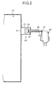
- Fig. 2 is a schematic partial cross sectional view illustrating the normal position detecting mechanism of Fig. 1, in a condition where the fan guard has been removed. As shown in these Figs.
- the normal position detecting mechanism of the fan guard of the present embodiment comprises: a plunger assembly 20 which is fixedly attached to an outer surface of an outer peripheral wall 11 of a heating chamber 10 of a heating apparatus, such as a microwave oven and a microwave heating oven; a micro switch 30; and a drive magnet 40 which is fixedly attached to a side edge of a mounting frame 7 of the fan guard.
- the plunger assembly 20 comprises: a bracket 21 which is fixedly attached to the outer surface of the outer peripheral wall 11 of non-magnetic material by using, for example, a screw; a plunger shaft 23 which is operatively mounted so as to be moved in an axial direction through a cylindrical guide portion 22 mounted on said bracket 21; a driven magnet 24 which is attached to one end of said plunger shaft 23; and a bias spring 26 which is disposed between a stopper portion 25 formed in the other end of said plunger shaft 23 and said bracket 21 so as to normally apply a bias force to said plunger shaft 23.
- the bias force of the bias spring 26 is applied in such a direction (in the right-hand direction in Figs, 1 and 2) that the plunger shaft 23 is moved in the direction that the driven magnet 24 is retracted from a mounting base face of the bracket 21. Further, the drive magnet 40 and the driven magnet 24 are designed to have their polarities opposite to each other.
- the micro switch 30 may be a general switch equipped with an action arm 31, and is fixedly installed in an outside of the outer peripheral wall 11 of the heating chamber 10 so that the action arm 31 may face to the plunger shaft 23.
- the driven magnet 24 is attracted by a magnetic force toward the drive magnet 40.
- This attracting force moves the plunger shaft 23 toward the outer peripheral wall 11 against the bias force of the bias spring 26.
- the other end of the plunger shaft 23 is moved to a position where it does not press the action arm 31 of the micro switch 30.
- the micro switch is brought into inactivated condition, which indicates that the fan guard is in the normal position to serve as the functional component of the heating apparatus.
- the heating apparatus is used under the condition where the fan guard is installed in the normal position, the interior of the heating chamber is getting dirty, so as the fan guard.
- the fan guard is taken out of the inside of the heating chamber so that the interior of the heating chamber and the removed fan guard can be washed.
- the fan guard needs to be reinstalled in the normal position within the heating chamber, so that it is brought into the condition as shown in Fig. 1.
- the detecting mechanism would be left in a condition as shown in Fig. 2.
- the magnets such as a drive magnet 40 and a driven magnet 24, have been employed, the present invention is not limited to this configuration, but either one of those magnets can be replaced with a piece of simple magnetic substance.
- Fig. 3 is a schematic partial cross sectional view illustrating a normal position detecting mechanism of a door in a heating apparatus according to another embodiment of the present invention, in a condition where the door has been normally closed
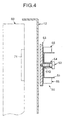
- Fig. 4 is a schematic partial cross sectional view illustrating the normal position detecting mechanism of Fig. 3, in a condition where the door has not been completely closed. As shown in Figs.
- the normal position detecting mechanism of the door in this embodiment comprises: a micro switch assembly 50 which is fixedly attached to an inner side of an edge frame 12 of an opening for providing an access to the inside of the heating chamber of the heating apparatus, such as a microwave oven and a microwave heating oven; and a drive magnet 71 which is located within a magnet case 70 arranged in an inner side edge portion of a door 60 for exposing or closing said opening of the heating chamber.
- Fig. 5 is a perspective view of the micro switch assembly 50.
- the micro switch assembly 50 comprises: a mounting bracket 51 having a hole 51A formed on a base portion for receiving a mounting screw; a shaft 52 movably inserted through a shaft bearing 51B (see Figs. 3 and 4) attached to said mounting bracket 51; an actuating iron core 53 mounted on one end of said shaft 52; a bias spring 54 installed surrounding the shaft 52 between a head portion of the shaft 52 and a stepped portion of the mounting bracket 51; and a pair of micro switches 55 attached respectively to each of both arm portions of the mounting bracket 51.
- a bias force of the bias spring 54 is applied in such a direction (in the right-hand direction in Figs, 3 and 4) that the shaft 52 is moved in the direction that the actuating iron core 53 is retracted from a mounting base face of the bracket 51.
- the drive magnet 71 mounted on the side edge of the door 60 is in such a position where it faces to the actuating iron core 53 mounted on the one end of the shaft 52 of the micro switch assembly 50 installed in the inner side of the edge frame 12 of the access opening of the heating chamber. Accordingly, the actuating iron core 53 is attracted by the magnetic force toward the drive magnet 71 against a bias force of the bias spring 54 so as to be moved away from the action piece 55A of the micro switch 55. Thereby, the micro switch 55 is brought into inactivated condition, and indicates that the door 60 has been completely closed.
- the normal position detecting mechanism in the above two embodiments has been described as a functional mechanism for detecting exclusively whether or not the functional component of the fan guard or the door is in its normal position
- a similar mechanism may be adapted to include a latching function, in addition to a normal position detecting function, of the functional component for bringing the functional component to be latched in a normal position by appropriately setting a magnitude of a magnet to be used.
- Such a normal position detecting and latching mechanism will now be briefly described in accordance with the configuration shown in Figs 3 to 5. In a condition where the door 60 has been completely closed as shown in Fig.
- the normal position detecting mechanism could be adapted to carry out, in addition to the function of normal position detecting, the function of latching the door by selecting a magnitude of the drive magnet 71 so that an attracting force of the drive magnet 71 applied to the actuating iron core 53 can provide a sufficient force for the door to be latched in the fully closed position.
- the micro switch 55 can also serve as a door switch so as to indicate that the door 60 has been latched in the fully closed position.
- the mechanism as shown in Figs. 1 and 2 to serve also as a latching mechanism by selecting appropriately the magnitude of the magnetic force to be generated by the magnets 40 and 24.
- latching mechanism Since such latching mechanism needs no additional component to be installed for latching, it can make the configuration thereof much simpler and less expensive, and further, since this latching mechanism needs no concave portion nor through hole to be formed in the outer peripheral wall or in the edge frame wall of the heating chamber which is exposed and closed by the door, therefore there would be no concern over the dirt to accumulate in the concave portion or the though hole, and also the cleaning thereof would be carried out more easily.
- micro switch has been employed, a modification may be applied to use a proximity switch, an optical sensor or the like as a substitute for the micro switch.
- a heat transfer path to a micro switch is blocked when a heating apparatus is under operation, which can eliminates a thermal affection to the micro switch.
- the normal position detecting mechanism according to the present invention may be easily modified to serve also as a latching mechanism without no additional component installed for the latching mechanism, the mechanism for both purpose may be made much simpler and less expensive.
- the heating apparatus could be provided with advantages in that the dirt is hard to accumulate and thereby the cleaning may be carried out easily.
Landscapes
- Physics & Mathematics (AREA)
- Electromagnetism (AREA)
- Electric Ovens (AREA)
- Constitution Of High-Frequency Heating (AREA)
- Control Of Resistance Heating (AREA)
Applications Claiming Priority (2)
| Application Number | Priority Date | Filing Date | Title |
|---|---|---|---|
| JP2000119075 | 2000-04-20 | ||
| JP2000119075A JP3810250B2 (ja) | 2000-04-20 | 2000-04-20 | 加熱機器における機能部の正常位置検知機構およびラッチ機構 |
Publications (3)
| Publication Number | Publication Date |
|---|---|
| EP1148767A2 true EP1148767A2 (de) | 2001-10-24 |
| EP1148767A3 EP1148767A3 (de) | 2004-02-04 |
| EP1148767B1 EP1148767B1 (de) | 2007-12-19 |
Family
ID=18630115
Family Applications (1)
| Application Number | Title | Priority Date | Filing Date |
|---|---|---|---|
| EP20010109593 Expired - Lifetime EP1148767B1 (de) | 2000-04-20 | 2001-04-18 | Erfassung einer richtigen Position und eines Schlossmechanismus bei einer Funktionskomponente in einer Heizvorrichtung |
Country Status (4)
| Country | Link |
|---|---|
| US (1) | US6552314B2 (de) |
| EP (1) | EP1148767B1 (de) |
| JP (1) | JP3810250B2 (de) |
| DE (1) | DE60131920T2 (de) |
Families Citing this family (11)
| Publication number | Priority date | Publication date | Assignee | Title |
|---|---|---|---|---|
| US20050236408A1 (en) * | 2004-04-08 | 2005-10-27 | Maytag Corporation | Door position sensing system for cooking appliance including combination heating system |
| US7775498B2 (en) * | 2007-06-26 | 2010-08-17 | Electrolux Home Products, Inc. | Anti-tip device for an appliance with an interlock switch |
| US20090160201A1 (en) * | 2007-12-20 | 2009-06-25 | Jeffrey Bennett Dold | Shock-absorbing strike assembly for closures |
| IT1396877B1 (it) * | 2009-11-13 | 2012-12-20 | Soldo S R L Socio Unico | Dispositivo interruttore ermetico ad azionamento magnetico |
| TWI469711B (zh) * | 2010-03-02 | 2015-01-11 | Hon Hai Prec Ind Co Ltd | 電子裝置及其鎖固結構 |
| CN102196692A (zh) * | 2010-03-05 | 2011-09-21 | 鸿富锦精密工业(深圳)有限公司 | 电子装置及其锁固结构 |
| US8674794B1 (en) * | 2010-10-15 | 2014-03-18 | Jennifer Oetjen | High security switch device |
| US9620317B1 (en) * | 2016-01-19 | 2017-04-11 | A-T Controls, Inc. | Magnetically-actuated, hermetically-sealed switch device |
| US11015631B2 (en) * | 2016-01-29 | 2021-05-25 | Hewlett-Packard Development Company, L.P. | Retractable locks |
| US11703823B2 (en) * | 2018-11-20 | 2023-07-18 | Inventio Ag | Method and assembly device for the automated determination of a drilling position of a drill hole |
| TWM589767U (zh) * | 2019-09-26 | 2020-01-21 | 統一超商股份有限公司 | 商用微波爐 |
Citations (1)
| Publication number | Priority date | Publication date | Assignee | Title |
|---|---|---|---|---|
| US4915431A (en) * | 1989-02-27 | 1990-04-10 | Rixson-Firemark Inc. | Electromagnetic lock having a self-adjusting switch assembly for door-movement alert |
Family Cites Families (4)
| Publication number | Priority date | Publication date | Assignee | Title |
|---|---|---|---|---|
| CA953392A (en) * | 1970-08-31 | 1974-08-20 | General Corporation (The) | Door locking system for microwave oven |
| JPS5757495A (en) * | 1980-09-22 | 1982-04-06 | Matsushita Electric Ind Co Ltd | High frequency heater |
| AU541443B2 (en) * | 1982-07-16 | 1985-01-10 | Tokyo Shibaura Denki Kabushiki Kaisha | Lock |
| US4573720A (en) * | 1983-09-01 | 1986-03-04 | Nicolai J Steven | Failsafe security lock |
-
2000
- 2000-04-20 JP JP2000119075A patent/JP3810250B2/ja not_active Expired - Lifetime
-
2001
- 2001-04-12 US US09/833,877 patent/US6552314B2/en not_active Expired - Fee Related
- 2001-04-18 DE DE2001631920 patent/DE60131920T2/de not_active Expired - Fee Related
- 2001-04-18 EP EP20010109593 patent/EP1148767B1/de not_active Expired - Lifetime
Patent Citations (1)
| Publication number | Priority date | Publication date | Assignee | Title |
|---|---|---|---|---|
| US4915431A (en) * | 1989-02-27 | 1990-04-10 | Rixson-Firemark Inc. | Electromagnetic lock having a self-adjusting switch assembly for door-movement alert |
Also Published As
| Publication number | Publication date |
|---|---|
| US20010032841A1 (en) | 2001-10-25 |
| EP1148767A3 (de) | 2004-02-04 |
| JP3810250B2 (ja) | 2006-08-16 |
| JP2001304576A (ja) | 2001-10-31 |
| DE60131920T2 (de) | 2008-12-18 |
| EP1148767B1 (de) | 2007-12-19 |
| DE60131920D1 (de) | 2008-01-31 |
| US6552314B2 (en) | 2003-04-22 |
Similar Documents
| Publication | Publication Date | Title |
|---|---|---|
| EP1148767B1 (de) | Erfassung einer richtigen Position und eines Schlossmechanismus bei einer Funktionskomponente in einer Heizvorrichtung | |
| AU2002330902B2 (en) | Magnetic switch | |
| JP5986073B2 (ja) | 磁気トリガー型近接スイッチ | |
| KR20080070535A (ko) | 플래튼 유지 기구 및 기록 유닛 | |
| US9136070B2 (en) | High security switch device | |
| JP2022549114A (ja) | ドア状態センサを有するスイッチキャビネットドアを備えたスイッチキャビネット | |
| JP6894699B2 (ja) | 扉開閉装置 | |
| JP2008255650A (ja) | クレセントセンサーユニット | |
| US10859053B2 (en) | Switch device | |
| EP3499479B1 (de) | Alarmperipheriegerät mit einer manipulationsschutzanordnung sowie manipulationsschutzanordnung | |
| KR100707464B1 (ko) | 냉장고의 개스킷 분리 장치 | |
| GB2450890A (en) | Magnetic contact | |
| JPH0650036A (ja) | 電気錠 | |
| KR200300365Y1 (ko) | 개폐감지용 도어록시스템 | |
| JP3644611B2 (ja) | X線装置用ケーシング | |
| JP2006012590A (ja) | 開閉検出装置 | |
| US5754109A (en) | Magnetic coin box sensor | |
| JP2002340655A (ja) | レベルスイッチ | |
| JP3152263B2 (ja) | ディスクプレーヤのチャッキング装置 | |
| JP3453165B2 (ja) | 液体タンクの液面検知装置 | |
| JPH0633911A (ja) | 流体圧アクチュエータのピストン位置検出装置 | |
| JPS5926461Y2 (ja) | 防犯感知器 | |
| SU624311A1 (ru) | Датчик положени | |
| JP3017981U (ja) | 衝突センサ | |
| JPH0363370A (ja) | マグネットラッチ |
Legal Events
| Date | Code | Title | Description |
|---|---|---|---|
| PUAI | Public reference made under article 153(3) epc to a published international application that has entered the european phase |
Free format text: ORIGINAL CODE: 0009012 |
|
| 17P | Request for examination filed |
Effective date: 20010510 |
|
| AK | Designated contracting states |
Kind code of ref document: A2 Designated state(s): AT BE CH CY DE DK ES FI FR GB GR IE IT LI LU MC NL PT SE TR |
|
| AX | Request for extension of the european patent |
Free format text: AL;LT;LV;MK;RO;SI |
|
| PUAL | Search report despatched |
Free format text: ORIGINAL CODE: 0009013 |
|
| AK | Designated contracting states |
Kind code of ref document: A3 Designated state(s): AT BE CH CY DE DK ES FI FR GB GR IE IT LI LU MC NL PT SE TR |
|
| AX | Request for extension of the european patent |
Extension state: AL LT LV MK RO SI |
|
| AKX | Designation fees paid |
Designated state(s): DE FR GB IT |
|
| 17Q | First examination report despatched |
Effective date: 20041109 |
|
| GRAP | Despatch of communication of intention to grant a patent |
Free format text: ORIGINAL CODE: EPIDOSNIGR1 |
|
| GRAJ | Information related to disapproval of communication of intention to grant by the applicant or resumption of examination proceedings by the epo deleted |
Free format text: ORIGINAL CODE: EPIDOSDIGR1 |
|
| GRAP | Despatch of communication of intention to grant a patent |
Free format text: ORIGINAL CODE: EPIDOSNIGR1 |
|
| GRAS | Grant fee paid |
Free format text: ORIGINAL CODE: EPIDOSNIGR3 |
|
| GRAA | (expected) grant |
Free format text: ORIGINAL CODE: 0009210 |
|
| AK | Designated contracting states |
Kind code of ref document: B1 Designated state(s): DE FR GB IT |
|
| REG | Reference to a national code |
Ref country code: GB Ref legal event code: FG4D |
|
| REF | Corresponds to: |
Ref document number: 60131920 Country of ref document: DE Date of ref document: 20080131 Kind code of ref document: P |
|
| ET | Fr: translation filed | ||
| PLBE | No opposition filed within time limit |
Free format text: ORIGINAL CODE: 0009261 |
|
| STAA | Information on the status of an ep patent application or granted ep patent |
Free format text: STATUS: NO OPPOSITION FILED WITHIN TIME LIMIT |
|
| 26N | No opposition filed |
Effective date: 20080922 |
|
| GBPC | Gb: european patent ceased through non-payment of renewal fee |
Effective date: 20080418 |
|
| PG25 | Lapsed in a contracting state [announced via postgrant information from national office to epo] |
Ref country code: DE Free format text: LAPSE BECAUSE OF NON-PAYMENT OF DUE FEES Effective date: 20081101 |
|
| REG | Reference to a national code |
Ref country code: FR Ref legal event code: ST Effective date: 20081231 |
|
| PG25 | Lapsed in a contracting state [announced via postgrant information from national office to epo] |
Ref country code: FR Free format text: LAPSE BECAUSE OF NON-PAYMENT OF DUE FEES Effective date: 20080430 |
|
| PG25 | Lapsed in a contracting state [announced via postgrant information from national office to epo] |
Ref country code: GB Free format text: LAPSE BECAUSE OF NON-PAYMENT OF DUE FEES Effective date: 20080418 |
|
| PG25 | Lapsed in a contracting state [announced via postgrant information from national office to epo] |
Ref country code: IT Free format text: LAPSE BECAUSE OF NON-PAYMENT OF DUE FEES Effective date: 20080418 |