EP1148286A2 - Kupplung zweier Fluid-Leitungen mit einem Kugelhahn - Google Patents
Kupplung zweier Fluid-Leitungen mit einem Kugelhahn Download PDFInfo
- Publication number
- EP1148286A2 EP1148286A2 EP01108361A EP01108361A EP1148286A2 EP 1148286 A2 EP1148286 A2 EP 1148286A2 EP 01108361 A EP01108361 A EP 01108361A EP 01108361 A EP01108361 A EP 01108361A EP 1148286 A2 EP1148286 A2 EP 1148286A2
- Authority
- EP
- European Patent Office
- Prior art keywords
- fluid
- ball valve
- line
- valve
- tap
- Prior art date
- Legal status (The legal status is an assumption and is not a legal conclusion. Google has not performed a legal analysis and makes no representation as to the accuracy of the status listed.)
- Granted
Links
- 239000012530 fluid Substances 0.000 title claims description 69
- 230000008878 coupling Effects 0.000 title claims description 13
- 238000010168 coupling process Methods 0.000 title claims description 13
- 238000005859 coupling reaction Methods 0.000 title claims description 13
- 210000000078 claw Anatomy 0.000 claims description 12
- 230000000903 blocking effect Effects 0.000 claims description 2
- 239000013589 supplement Substances 0.000 claims description 2
- 238000003780 insertion Methods 0.000 description 3
- 230000037431 insertion Effects 0.000 description 3
- 238000000926 separation method Methods 0.000 description 2
- 239000007787 solid Substances 0.000 description 2
- 238000011161 development Methods 0.000 description 1
- 230000018109 developmental process Effects 0.000 description 1
- 239000003949 liquefied natural gas Substances 0.000 description 1
Images


Classifications
-
- F—MECHANICAL ENGINEERING; LIGHTING; HEATING; WEAPONS; BLASTING
- F16—ENGINEERING ELEMENTS AND UNITS; GENERAL MEASURES FOR PRODUCING AND MAINTAINING EFFECTIVE FUNCTIONING OF MACHINES OR INSTALLATIONS; THERMAL INSULATION IN GENERAL
- F16L—PIPES; JOINTS OR FITTINGS FOR PIPES; SUPPORTS FOR PIPES, CABLES OR PROTECTIVE TUBING; MEANS FOR THERMAL INSULATION IN GENERAL
- F16L37/00—Couplings of the quick-acting type
- F16L37/28—Couplings of the quick-acting type with fluid cut-off means
- F16L37/38—Couplings of the quick-acting type with fluid cut-off means with fluid cut-off means in only one of two pipe-end fittings
- F16L37/40—Couplings of the quick-acting type with fluid cut-off means with fluid cut-off means in only one of two pipe-end fittings with a lift valve being opened automatically when the coupling is applied
- F16L37/407—Couplings of the quick-acting type with fluid cut-off means with fluid cut-off means in only one of two pipe-end fittings with a lift valve being opened automatically when the coupling is applied the lift valve being of the ball type
Definitions
- the invention relates to a coupling of two fluid lines with one Ball valve blocking or releasing both line ends.
- To the technical environment is referred to DE 36 02 775 A1 for example.
- the solution to this problem is characterized in that the (in coupled Condition only) ball valve made of two essentially hemispherical There are halves of the valve, one of which is the first fluid line and the another is assigned to the second fluid line and with which the assigned one Fluid line can be shut off, and being adjacent to one another End faces of the fluid lines the two faucet halves to im supplement essential spherical ball valve, which after twisting both releases a fluid transfer through the two line ends as well the two fluid lines in this tap position are inseparable connects.
- Advantageous further developments are the content of the subclaims.
- a ball valve is formed by a so-called full ball, i.e. through an essentially spherical body that is central with one running passage opening, hereinafter also called ball valve channel, is provided.
- This solid ball lies with a diameter circle on the inner wall of the circular fluid line in cross section and can starting from a position in which the ball valve channel is parallel to Longitudinal axis of the fluid line is aligned, usually by 90 ° in one position are rotated, in which the ball valve channel is then perpendicular to Longitudinal axis of the fluid line runs.
- the Ball valve In the former position, the Ball valve the fluid line or its line end or more precisely one Fluid overflow through their line ends freely, while the ball valve in the second mentioned position shuts off the line end.
- a single so-called full ball is now in two so-called halves of the tap divided, each essentially forming a hemisphere and each one of the interconnectable (or separable) Fluid lines are assigned.
- Each of these half-balls or half-cocks can then shut off the associated fluid line.
- they are the two Fluid lines or their line ends coupled to each other, so are the two halves of the tap at the same time, a full ball forming ball valve, which can then be opened, so that a fluid transfer from one fluid line to the other fluid line is possible.
- This ball valve takes over according to the invention yet another, namely a coupling function, in which the line ends releasing position of the composed of the two halves of the tap The two fluid lines through this ball valve appropriately mechanically inseparable and are therefore coupled to one another.
- This can preferably be coupled to one another by means of two claws which rest on one another the spherical surface of a faucet half diametrically opposite each other are arranged, and two correspondingly on the other half of the tap provided webs take place, the webs in the associated claws are insertable and each tap half in the wall of the associated fluid line is rotatably guided over the claws or over the webs.
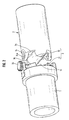
- FIGS. 1-3 a coupling according to the invention is highly abstracted and shown in perspective to the essential. 1 shows only one fluid line and the two valve halves, the ball valve, while FIG. 2 also shows the second fluid line. Finally, FIG. 3 shows the fluid lines connected or coupled to one another.
- a second one also having a circular cross section Fluid line 2 coupled to its line end 2a or its end face 2a shall be.
- this should also apply to a separation of these two fluid lines 1, 2 from each other the individual line ends 1a, 2a be lockable.
- the faucet half 31 is the first fluid line 1 and second tap half 32 assigned to the second fluid line 2.
- the tap half 32 does not have the exact shape of a hemisphere, but rather has a projection or the like protruding from the flat side of this hemisphere, which is designed here in the form of a cylinder halved along its axis. Along said cylinder axis, and thus by both the projection and across the hemisphere through a so-called.
- Ball valve channel runs 33. Located at the ball valve channel 33 and the valve half 32 in the assembled state according to Figure 3 in the in figure 2 shown position, it is obviously not possible for fluid to pass between the two fluid lines 1, 2, so that the line ends 1a, 2a are then shut off.
- the ball valve channel 33 lies in the direction of the (not explicitly shown) longitudinal axes of the fluid lines 1, 2 coupled to one another, so that then a fluid transfer through the ball valve 3 is possible, ie that the line ends 1a, 2a of the fluid lines 1, 2 are then released.
- valve half 31 installed in the associated fluid line 1.
- the latter is also not an exact hemisphere, but this valve half 31, like the valve half 32, is in the respective fluid line 1 or 2 installed so that it protrudes with its spherical, curved surface into the fluid line 1 or 2, ie the so-called cut surface of each hemisphere faces the respective line end 1a or 2a.
- the so-called cut surface of the substantially hemispherical half of the valve 31 is of course designed such that it can be supplemented with the other half of the valve 32 to form a solid ball, that is to say a suitably designed recess or recess is provided on the cut surface of the half of the valve 31, into which the so-called projection on the cut surface of the tap half 32 can be inserted if the two fluid lines 1, 2 are assembled with the built-in tap halves 31, 32 such that the end faces 1 a, 2 a adjoin one another, as shown in FIG. 3 .
- each tap half 31, 32 is guided or supported in the wall of the associated fluid line 1 or 2.
- This bearing is designed to be rotatable, such that in the assembled state according to FIG. 3, the webs 35 together with the claws 34 form one or the already mentioned axis of rotation 4 for the ball valve 3 then assembled.
- the ball valve 3 can now be rotated by 90 ° about this axis of rotation 4, after which the ball valve channel 33 runs in the direction of the common longitudinal axis of the fluid lines 1, 2 and the previously blocked line ends 1a, 2a are released, so that now a fluid transfer between the two fluid lines 1, 2 is possible through the open ball valve 3.
- the insertion openings 34a of the claws 34 are aligned transversely to the common longitudinal axis of the fluid lines 1, 2, so that in this coupled and opened state the fluid lines 1, 2 are not apart can be separated, ie in this state the coupling formed by the ball valve 3 cannot be opened.
- the ball valve 3 in its entirety, and thus also the two valve halves 31, 32, has previously been brought into a position according to FIG. 2 which blocks the fluid lines 1, 2 or their line ends 1a, 2a.
Landscapes
- Engineering & Computer Science (AREA)
- General Engineering & Computer Science (AREA)
- Mechanical Engineering (AREA)
- Taps Or Cocks (AREA)
- Quick-Acting Or Multi-Walled Pipe Joints (AREA)
- Multiple-Way Valves (AREA)
- Joints Allowing Movement (AREA)
Abstract
Description
- 1,2
- Fluid-Leitung
- 1a
- Leitungsende oder Stirnfläche der ersten Fluid-Leitung 1
- 2a
- Leitungsende oder Stirnfläche der zweiten Fluid-Leitung 2
- 3
- Kugelhahn
- 31
- Hahnhälfte, der Fluid-Leitung 1 zugeordnet
- 32
- Hahnhälfte, der Fluid-Leitung 1 zugeordnet
- 33
- Kugelhahn-Kanal
- 34
- Klaue
- 34a
- Einführöffnung von 34
- 35
- Steg
- 36
- Rändelrad
- 4
- Drehachse
- 5
- Pfeilrichtung: Verdrehen von 3
Claims (3)
- Kupplung zweier Fluid-Leitungen (1, 2) mit einem die beiden Leitungsenden (1a, 2a) absperrenden oder freigebenden Kugelhahn (3), der aus zwei im wesentlichen halbkugelförmigen Hahnhälften (31, 32) besteht, von denen eine der ersten Fluid-Leitung (1) und die andere der zweiten Fluid-Leitung (2) zugeordnet ist und mit denen jeweils die zugeordnete Fluidleitung absperrbar ist, und wobei sich bei aneinander angrenzenden Stirnflächen (1a, 2a) der Fluid-Leitungen (1, 2) die beiden Hahnhälften (31, 32) zum im wesentlichen kugelförmigen Kugelhahn (3) ergänzen, der nach Verdrehen sowohl einen Fluid-Übertritt durch die beiden Leitungsenden (1a, 2a) freigibt als auch die beiden Fluid-Leitungen (1, 2) in dieser Hahnposition untrennbar miteinander verbindet.
- Kupplung nach Anspruch 1,
wobei die eine Hahnhälfte (32) mit zwei auf der Kugeloberfläche diametral angeordneten Klauen (34) versehen ist, in die diametral angeordnete Stege (35) der anderen Hahnhälfte (31) einführbar sind und jede Hahnhälfte (31, 32) in der Wand der zugeordneten Fluid-Leitung (1, 2) über die Klauen (34) oder über die Stege (35) verdrehbar geführt ist. - Kupplung nach Anspruch 1 oder 2,
wobei ein einen Fluid-Übertitt durch den geöffneten Kugelhahn (3) ermöglichender Kugelhahn-Kanal (33) nur in einer der beiden Hahnhälften (32) vorgesehen ist.
Applications Claiming Priority (2)
| Application Number | Priority Date | Filing Date | Title |
|---|---|---|---|
| DE10019526A DE10019526A1 (de) | 2000-04-20 | 2000-04-20 | Kupplung zweier Fluid-Leitungen mit einem Kugelhahn |
| DE10019526 | 2000-04-20 |
Publications (3)
| Publication Number | Publication Date |
|---|---|
| EP1148286A2 true EP1148286A2 (de) | 2001-10-24 |
| EP1148286A3 EP1148286A3 (de) | 2003-05-28 |
| EP1148286B1 EP1148286B1 (de) | 2004-09-22 |
Family
ID=7639396
Family Applications (1)
| Application Number | Title | Priority Date | Filing Date |
|---|---|---|---|
| EP01108361A Expired - Lifetime EP1148286B1 (de) | 2000-04-20 | 2001-04-03 | Kupplung zweier Fluid-Leitungen mit einem Kugelhahn |
Country Status (2)
| Country | Link |
|---|---|
| EP (1) | EP1148286B1 (de) |
| DE (2) | DE10019526A1 (de) |
Cited By (1)
| Publication number | Priority date | Publication date | Assignee | Title |
|---|---|---|---|---|
| WO2010105722A1 (de) * | 2009-03-14 | 2010-09-23 | H & B Electronic Gmbh & Co. Kg | Kupplungsanordnung |
Families Citing this family (2)
| Publication number | Priority date | Publication date | Assignee | Title |
|---|---|---|---|---|
| DE102006016401B3 (de) * | 2006-04-07 | 2007-08-30 | Witt, Florian M. | Kupplung zweier Fluidleitungsenden mit Halbkugelabschnitten |
| DE102023211332B3 (de) | 2023-11-14 | 2024-10-31 | Carl Zeiss Smt Gmbh | Lithographiesystem mit einer Kupplung zum Trennen von Leitungsabschnitten |
Citations (1)
| Publication number | Priority date | Publication date | Assignee | Title |
|---|---|---|---|---|
| DE3602775A1 (de) | 1986-01-30 | 1987-08-20 | Pfannenschmidt Erhard | Kupplung zur verbindung eines feststehenden rohres oder dergleichen mit einem beweglichen rohr oder schlauch |
Family Cites Families (3)
| Publication number | Priority date | Publication date | Assignee | Title |
|---|---|---|---|---|
| US2373925A (en) * | 1942-08-05 | 1945-04-17 | Thompson Prod Inc | Coupling seal construction |
| US2458910A (en) * | 1945-05-16 | 1949-01-11 | Thompson Prod Inc | Quick disconnect coupling |
| US5286129A (en) * | 1991-08-07 | 1994-02-15 | Crater Corporation | Coupling device and methods of coupling |
-
2000
- 2000-04-20 DE DE10019526A patent/DE10019526A1/de not_active Withdrawn
-
2001
- 2001-04-03 DE DE50103703T patent/DE50103703D1/de not_active Expired - Lifetime
- 2001-04-03 EP EP01108361A patent/EP1148286B1/de not_active Expired - Lifetime
Patent Citations (1)
| Publication number | Priority date | Publication date | Assignee | Title |
|---|---|---|---|---|
| DE3602775A1 (de) | 1986-01-30 | 1987-08-20 | Pfannenschmidt Erhard | Kupplung zur verbindung eines feststehenden rohres oder dergleichen mit einem beweglichen rohr oder schlauch |
Cited By (3)
| Publication number | Priority date | Publication date | Assignee | Title |
|---|---|---|---|---|
| WO2010105722A1 (de) * | 2009-03-14 | 2010-09-23 | H & B Electronic Gmbh & Co. Kg | Kupplungsanordnung |
| EP2423555A1 (de) | 2009-03-14 | 2012-02-29 | H & B Electronic GmbH & Co. KG | Kupplungsanordnung |
| US8215971B2 (en) | 2009-03-14 | 2012-07-10 | H & B Electronic GmbH & Co., KG | Coupling arrangement |
Also Published As
| Publication number | Publication date |
|---|---|
| DE50103703D1 (de) | 2004-10-28 |
| DE10019526A1 (de) | 2001-10-25 |
| EP1148286B1 (de) | 2004-09-22 |
| EP1148286A3 (de) | 2003-05-28 |
Similar Documents
| Publication | Publication Date | Title |
|---|---|---|
| DE3117935C2 (de) | ||
| DE19814047C1 (de) | Patientenkonnektor | |
| DE3407744C2 (de) | Handspritzpistole für ein Hochdruckreinigungsgerät | |
| DE2138103A1 (de) | Steckkupplung fuer rohr- und schlauchleitungen | |
| EP0013393A1 (de) | Rohrleitungskupplung | |
| DE4203417A1 (de) | Schnelltrennkupplung | |
| EP1264127B1 (de) | Drehbarer absperrhahn für eine steckkupplung mit abgewinkeltem anschlussstutzen | |
| DE102019132411A1 (de) | Zapfventil | |
| EP0096649B1 (de) | Unter Druck und auch drucklos kuppelbare Schnellverschlusskupplung, insbesondere für Hydraulikleitungen | |
| EP1525417B1 (de) | Ventil, insbesondere dampfventil | |
| EP1148286B1 (de) | Kupplung zweier Fluid-Leitungen mit einem Kugelhahn | |
| EP4219999A1 (de) | Fluidkupplung | |
| DE912282C (de) | Leitungskupplung | |
| DE7217008U (de) | Absperrhahn mit ueber stangen gegen dichtungssitz pressbarem kuekenteil | |
| DE19949870C1 (de) | Abzweighahn für molchbare Rohrleitungssysteme | |
| DE1068962B (de) | ||
| DE1060202B (de) | Kugelhahnkupplung, insbesondere fuer Tankanlagen von fluessigen Brennstoffen | |
| DE4318840A1 (de) | Kupplung zum Verbinden von Hydraulikleitungen | |
| DE1810282C3 (de) | Ventilrohrkupplung für eine Druckleitung | |
| DE3844322A1 (de) | Trennbares doppelventil | |
| DE690270C (de) | Absperrhahn mit Kugelgehaeuse und kugeligem Hahnkueken | |
| DE952307C (de) | Selbsttaetige Rohr- oder Schlauchkupplung | |
| CH423860A (de) | Sandstreuvorrichtung an einem Fahrzeug | |
| CH378624A (de) | Absperrhahn aus Kunststoff | |
| DE102005045154A1 (de) | Fluidkupplung mit Ventilanordnung |
Legal Events
| Date | Code | Title | Description |
|---|---|---|---|
| PUAI | Public reference made under article 153(3) epc to a published international application that has entered the european phase |
Free format text: ORIGINAL CODE: 0009012 |
|
| AK | Designated contracting states |
Kind code of ref document: A2 Designated state(s): AT BE CH CY DE DK ES FI FR GB GR IE IT LI LU MC NL PT SE TR |
|
| AX | Request for extension of the european patent |
Free format text: AL;LT;LV;MK;RO;SI |
|
| PUAL | Search report despatched |
Free format text: ORIGINAL CODE: 0009013 |
|
| AK | Designated contracting states |
Designated state(s): AT BE CH CY DE DK ES FI FR GB GR IE IT LI LU MC NL PT SE TR |
|
| AX | Request for extension of the european patent |
Extension state: AL LT LV MK RO SI |
|
| RIC1 | Information provided on ipc code assigned before grant |
Ipc: 7F 16L 37/40 A Ipc: 7F 16L 37/30 B |
|
| 17P | Request for examination filed |
Effective date: 20030423 |
|
| AKX | Designation fees paid |
Designated state(s): DE FR GB IT |
|
| GRAP | Despatch of communication of intention to grant a patent |
Free format text: ORIGINAL CODE: EPIDOSNIGR1 |
|
| GRAS | Grant fee paid |
Free format text: ORIGINAL CODE: EPIDOSNIGR3 |
|
| GRAA | (expected) grant |
Free format text: ORIGINAL CODE: 0009210 |
|
| AK | Designated contracting states |
Kind code of ref document: B1 Designated state(s): DE FR GB IT |
|
| REG | Reference to a national code |
Ref country code: GB Ref legal event code: FG4D Free format text: NOT ENGLISH |
|
| REG | Reference to a national code |
Ref country code: IE Ref legal event code: FG4D Free format text: GERMAN |
|
| GBT | Gb: translation of ep patent filed (gb section 77(6)(a)/1977) | ||
| REF | Corresponds to: |
Ref document number: 50103703 Country of ref document: DE Date of ref document: 20041028 Kind code of ref document: P |
|
| REG | Reference to a national code |
Ref country code: IE Ref legal event code: FD4D |
|
| ET | Fr: translation filed | ||
| PLBE | No opposition filed within time limit |
Free format text: ORIGINAL CODE: 0009261 |
|
| STAA | Information on the status of an ep patent application or granted ep patent |
Free format text: STATUS: NO OPPOSITION FILED WITHIN TIME LIMIT |
|
| 26N | No opposition filed |
Effective date: 20050623 |
|
| PGFP | Annual fee paid to national office [announced via postgrant information from national office to epo] |
Ref country code: DE Payment date: 20130605 Year of fee payment: 13 Ref country code: GB Payment date: 20130425 Year of fee payment: 13 |
|
| PGFP | Annual fee paid to national office [announced via postgrant information from national office to epo] |
Ref country code: IT Payment date: 20130418 Year of fee payment: 13 Ref country code: FR Payment date: 20130605 Year of fee payment: 13 |
|
| REG | Reference to a national code |
Ref country code: DE Ref legal event code: R119 Ref document number: 50103703 Country of ref document: DE |
|
| GBPC | Gb: european patent ceased through non-payment of renewal fee |
Effective date: 20140403 |
|
| REG | Reference to a national code |
Ref country code: FR Ref legal event code: ST Effective date: 20141231 |
|
| PG25 | Lapsed in a contracting state [announced via postgrant information from national office to epo] |
Ref country code: DE Free format text: LAPSE BECAUSE OF NON-PAYMENT OF DUE FEES Effective date: 20141101 Ref country code: GB Free format text: LAPSE BECAUSE OF NON-PAYMENT OF DUE FEES Effective date: 20140403 |
|
| REG | Reference to a national code |
Ref country code: DE Ref legal event code: R119 Ref document number: 50103703 Country of ref document: DE Effective date: 20141101 |
|
| PG25 | Lapsed in a contracting state [announced via postgrant information from national office to epo] |
Ref country code: FR Free format text: LAPSE BECAUSE OF NON-PAYMENT OF DUE FEES Effective date: 20140430 |
|
| PG25 | Lapsed in a contracting state [announced via postgrant information from national office to epo] |
Ref country code: IT Free format text: LAPSE BECAUSE OF NON-PAYMENT OF DUE FEES Effective date: 20140403 |