EP1148200A2 - Flap holder - Google Patents
Flap holder Download PDFInfo
- Publication number
- EP1148200A2 EP1148200A2 EP01109087A EP01109087A EP1148200A2 EP 1148200 A2 EP1148200 A2 EP 1148200A2 EP 01109087 A EP01109087 A EP 01109087A EP 01109087 A EP01109087 A EP 01109087A EP 1148200 A2 EP1148200 A2 EP 1148200A2
- Authority
- EP
- European Patent Office
- Prior art keywords
- flap
- arm part
- side arm
- control
- spring
- Prior art date
- Legal status (The legal status is an assumption and is not a legal conclusion. Google has not performed a legal analysis and makes no representation as to the accuracy of the status listed.)
- Granted
Links
Images
Classifications
-
- E—FIXED CONSTRUCTIONS
- E05—LOCKS; KEYS; WINDOW OR DOOR FITTINGS; SAFES
- E05D—HINGES OR SUSPENSION DEVICES FOR DOORS, WINDOWS OR WINGS
- E05D11/00—Additional features or accessories of hinges
- E05D11/10—Devices for preventing movement between relatively-movable hinge parts
- E05D11/1028—Devices for preventing movement between relatively-movable hinge parts for maintaining the hinge in two or more positions, e.g. intermediate or fully open
- E05D11/105—Devices for preventing movement between relatively-movable hinge parts for maintaining the hinge in two or more positions, e.g. intermediate or fully open the maintaining means acting perpendicularly to the pivot axis
- E05D11/1064—Devices for preventing movement between relatively-movable hinge parts for maintaining the hinge in two or more positions, e.g. intermediate or fully open the maintaining means acting perpendicularly to the pivot axis with a coil spring perpendicular to the pivot axis
-
- E—FIXED CONSTRUCTIONS
- E05—LOCKS; KEYS; WINDOW OR DOOR FITTINGS; SAFES
- E05F—DEVICES FOR MOVING WINGS INTO OPEN OR CLOSED POSITION; CHECKS FOR WINGS; WING FITTINGS NOT OTHERWISE PROVIDED FOR, CONCERNED WITH THE FUNCTIONING OF THE WING
- E05F1/00—Closers or openers for wings, not otherwise provided for in this subclass
- E05F1/08—Closers or openers for wings, not otherwise provided for in this subclass spring-actuated, e.g. for horizontally sliding wings
- E05F1/10—Closers or openers for wings, not otherwise provided for in this subclass spring-actuated, e.g. for horizontally sliding wings for swinging wings, e.g. counterbalance
- E05F1/1041—Closers or openers for wings, not otherwise provided for in this subclass spring-actuated, e.g. for horizontally sliding wings for swinging wings, e.g. counterbalance with a coil spring perpendicular to the pivot axis
- E05F1/105—Closers or openers for wings, not otherwise provided for in this subclass spring-actuated, e.g. for horizontally sliding wings for swinging wings, e.g. counterbalance with a coil spring perpendicular to the pivot axis with a compression spring
- E05F1/1058—Closers or openers for wings, not otherwise provided for in this subclass spring-actuated, e.g. for horizontally sliding wings for swinging wings, e.g. counterbalance with a coil spring perpendicular to the pivot axis with a compression spring for counterbalancing
-
- E—FIXED CONSTRUCTIONS
- E05—LOCKS; KEYS; WINDOW OR DOOR FITTINGS; SAFES
- E05F—DEVICES FOR MOVING WINGS INTO OPEN OR CLOSED POSITION; CHECKS FOR WINGS; WING FITTINGS NOT OTHERWISE PROVIDED FOR, CONCERNED WITH THE FUNCTIONING OF THE WING
- E05F5/00—Braking devices, e.g. checks; Stops; Buffers
- E05F5/02—Braking devices, e.g. checks; Stops; Buffers specially for preventing the slamming of swinging wings during final closing movement, e.g. jamb stops
-
- E—FIXED CONSTRUCTIONS
- E05—LOCKS; KEYS; WINDOW OR DOOR FITTINGS; SAFES
- E05Y—INDEXING SCHEME RELATING TO HINGES OR OTHER SUSPENSION DEVICES FOR DOORS, WINDOWS OR WINGS AND DEVICES FOR MOVING WINGS INTO OPEN OR CLOSED POSITION, CHECKS FOR WINGS AND WING FITTINGS NOT OTHERWISE PROVIDED FOR, CONCERNED WITH THE FUNCTIONING OF THE WING
- E05Y2201/00—Constructional elements; Accessories therefore
- E05Y2201/60—Suspension or transmission members; Accessories therefore
- E05Y2201/604—Transmission members
-
- E—FIXED CONSTRUCTIONS
- E05—LOCKS; KEYS; WINDOW OR DOOR FITTINGS; SAFES
- E05Y—INDEXING SCHEME RELATING TO HINGES OR OTHER SUSPENSION DEVICES FOR DOORS, WINDOWS OR WINGS AND DEVICES FOR MOVING WINGS INTO OPEN OR CLOSED POSITION, CHECKS FOR WINGS AND WING FITTINGS NOT OTHERWISE PROVIDED FOR, CONCERNED WITH THE FUNCTIONING OF THE WING
- E05Y2201/00—Constructional elements; Accessories therefore
- E05Y2201/60—Suspension or transmission members; Accessories therefore
- E05Y2201/622—Suspension or transmission members elements
- E05Y2201/624—Arms
-
- E—FIXED CONSTRUCTIONS
- E05—LOCKS; KEYS; WINDOW OR DOOR FITTINGS; SAFES
- E05Y—INDEXING SCHEME RELATING TO HINGES OR OTHER SUSPENSION DEVICES FOR DOORS, WINDOWS OR WINGS AND DEVICES FOR MOVING WINGS INTO OPEN OR CLOSED POSITION, CHECKS FOR WINGS AND WING FITTINGS NOT OTHERWISE PROVIDED FOR, CONCERNED WITH THE FUNCTIONING OF THE WING
- E05Y2201/00—Constructional elements; Accessories therefore
- E05Y2201/60—Suspension or transmission members; Accessories therefore
- E05Y2201/622—Suspension or transmission members elements
- E05Y2201/638—Cams; Ramps
-
- E—FIXED CONSTRUCTIONS
- E05—LOCKS; KEYS; WINDOW OR DOOR FITTINGS; SAFES
- E05Y—INDEXING SCHEME RELATING TO HINGES OR OTHER SUSPENSION DEVICES FOR DOORS, WINDOWS OR WINGS AND DEVICES FOR MOVING WINGS INTO OPEN OR CLOSED POSITION, CHECKS FOR WINGS AND WING FITTINGS NOT OTHERWISE PROVIDED FOR, CONCERNED WITH THE FUNCTIONING OF THE WING
- E05Y2201/00—Constructional elements; Accessories therefore
- E05Y2201/60—Suspension or transmission members; Accessories therefore
- E05Y2201/622—Suspension or transmission members elements
- E05Y2201/696—Screw mechanisms
- E05Y2201/702—Spindles; Worms
-
- E—FIXED CONSTRUCTIONS
- E05—LOCKS; KEYS; WINDOW OR DOOR FITTINGS; SAFES
- E05Y—INDEXING SCHEME RELATING TO HINGES OR OTHER SUSPENSION DEVICES FOR DOORS, WINDOWS OR WINGS AND DEVICES FOR MOVING WINGS INTO OPEN OR CLOSED POSITION, CHECKS FOR WINGS AND WING FITTINGS NOT OTHERWISE PROVIDED FOR, CONCERNED WITH THE FUNCTIONING OF THE WING
- E05Y2600/00—Mounting or coupling arrangements for elements provided for in this subclass
- E05Y2600/10—Adjustable or movable
- E05Y2600/20—Adjustable or movable characterised by the movement transmission
-
- E—FIXED CONSTRUCTIONS
- E05—LOCKS; KEYS; WINDOW OR DOOR FITTINGS; SAFES
- E05Y—INDEXING SCHEME RELATING TO HINGES OR OTHER SUSPENSION DEVICES FOR DOORS, WINDOWS OR WINGS AND DEVICES FOR MOVING WINGS INTO OPEN OR CLOSED POSITION, CHECKS FOR WINGS AND WING FITTINGS NOT OTHERWISE PROVIDED FOR, CONCERNED WITH THE FUNCTIONING OF THE WING
- E05Y2800/00—Details, accessories and auxiliary operations not otherwise provided for
- E05Y2800/20—Combinations of elements
- E05Y2800/22—Combinations of elements of not identical elements of the same category, e.g. combinations of not identical springs
-
- E—FIXED CONSTRUCTIONS
- E05—LOCKS; KEYS; WINDOW OR DOOR FITTINGS; SAFES
- E05Y—INDEXING SCHEME RELATING TO HINGES OR OTHER SUSPENSION DEVICES FOR DOORS, WINDOWS OR WINGS AND DEVICES FOR MOVING WINGS INTO OPEN OR CLOSED POSITION, CHECKS FOR WINGS AND WING FITTINGS NOT OTHERWISE PROVIDED FOR, CONCERNED WITH THE FUNCTIONING OF THE WING
- E05Y2900/00—Application of doors, windows, wings or fittings thereof
- E05Y2900/20—Application of doors, windows, wings or fittings thereof for furnitures, e.g. cabinets
Definitions
- the invention relates to a flap holder for a vertically pivotable arranged on a furniture body, by swiveling it up opening flap to hold the flap in its open position by means of a spring arrangement.
- the top cabinet compartment is particularly common in tall cabinets by one hinged to the furniture body in the area of its upper edge
- the flap is closed and swiveled upwards to open it becomes.
- a flap holder is regularly assigned to such a flap, who is supposed to keep the flap in its open position.
- flap holders contain a lever linkage and a spring arrangement, so that the lever linkage runs over a dead center position. If you close the flap, it will reach after the Dead center not only their weight but also the spring force which can lead to the flap slamming violently.
- the object of the present invention to create a flap holder principle with which one in a relatively simple manner to the respective requirements corresponding movement behavior of the flap can receive.
- the flap holder a pivotally connectable to the flap about a pivot axis flap-side arm part and a swivel around a swivel axis connected to a fitting part to be attached to the furniture body has body-side arm part, the flap or end areas opposite the furniture body about an axis of articulation are pivotally connected to each other so that a toggle-like Arrangement is formed, and that between the body side Arm part and the fitting part of a first control device and between the body-side arm part and the flap-side Arm part a second control device is effective, the two Control devices each have a pressure piece and a control curve included by one of the other control device independent spring device held against each other are, so that the flap holder depending on the Swing angle of the flap force exerted on the flap from two force components occurring in each case on one of the control devices put together.
- the body-side swings Arm section around the body-side pivot axis. Also swivel the two arm parts on the hinge axis relative to each other. These two swiveling movements are forceful by the two Control devices and in connection with the spring devices determined by the course of the control curves. Since the two control devices are independent of one another, one obtains two power components, depending on the course of the control curves be opposite to each other in certain swivel angle ranges or can also increase or be zero.
- each of the two control cams can face one Pivot axis or hinge axis at least essentially Have concentric curve area, being in the closed position and in the open position with one of the control devices the pressure piece rests on the concentric curve area.
- the two control devices when opening and closing the flap one after the other with one in between arranged overlap area are effective.
- At at least one of the spring devices adjustable the spring force is. This way you can use the flap holder without any other changes to the personal needs of the user or adjust the valve weight.
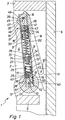
- the upper front area of a cabinet is shown in the drawing in vertical cross section, so that from the cabinet body 1 one of the side walls 2, the top wall forming the cabinet ceiling 3 and a shelf 5 delimiting the uppermost compartment 4 below are.
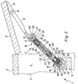
- the front of the compartment 4 is a flap 6 assigned between a vertical, closing the compartment 4 Closed position (Fig. 1) and a swung up, access to the open cabinet position 4 (Fig. 2) is pivotally attached to the body 1.
- the swivel fitting, over which the upper end region of the flap in the closed position 6 is pivotally connected to the body 1, was in the Drawing omitted. It is of common construction and interested otherwise no further in the present context.
- the flap 6 is not only about the swivel fitting Flap holder 7 with the cabinet body 1 and with it Side wall 2 connected. With the help of the flap holder 7 Flap 6 held in its open position shown in FIG. 2.
- the flap holder 7 has a flap-side arm part 8 and Body-side arm part 9, which has a toggle-like arrangement form.
- the relevant end of the flap arm part 8 pivotally connected to the flap 6 about a pivot axis 10.
- the articulation axis 10 sits on a fastening shoe 11, to the flap 6, in the embodiment to the in the closed position the inside of the flap facing the inside of the cabinet, is screwed on.
- the arm part 8 on the flap side opposite end of the body-side arm part 9 is against it pivotable about a pivot axis 12 with one to the flap holder 7 belonging fitting part 13, which is fixed to the furniture body, attached to the side wall 2 in the embodiment becomes.
- the facing end areas of the two arm parts 8, 9 are pivotally connected to one another via a joint axis 14, so that the two arm parts 8, 9 are arranged overall in a V-like manner are.
- 1 are in the closed position both arm parts 8.9 under a relatively small point Angle to each other, with both arm parts, starting from the Flap 6 or the fitting part 13, extend upwards.
- 2 are the two arm parts 8.9 from each other swung away and almost assume a stretched position.
- the flap holder 7 contains two control devices 15, 16, which the first control device 15 between the body side Arm part 9 and the fitting part 13 and the second control device 16 between the body-side arm part 9 and the flap-side Arm part 8 is effective.
- the two control devices 15, 16 contain in each case one pressure piece 17 or 18 and one control cam 19 or 20, against each other by a spring device 21 or 22 being held.
- the two spring devices 21, 22 independently of each other.
- the two pressure pieces 17, 18 are on body-side arm part 9 arranged. Accordingly located the control cam 19 assigned to the pressure piece 17 on the body side Fitting part 13 and that assigned to the pressure piece 18 Control curve 20 on the flap-side arm part 8. In principle, could with one and / or another control device the arrangement also be the other way round so that the control curve on the cabinet side Arm part sits.
- the spring device 21 or 22 acts on the respective pressure piece 17 or 18 towards the facing control curve 19 or 20.
- the body-side arm part 9 has a tubular shape.
- the two pressure pieces 17, 18 are tubular inside this body-side arm part 9 housed.
- embodiments are also conceivable in which only one of the Thrust pieces located inside the arm part.
- Each pressure piece 17 or, respectively, arranged on the body-side arm part 9 18 has a bearing section which is guided in a longitudinally displaceable manner on the arm part 9 23 or 24 and one on the bearing section 23 or 24 rotatable stored, lying on the relevant cam 19 or 20 Pressure roller 25 or 26, which when pivoting the flap 6 rolls on the control curve 19 or 20.
- the two spring devices 21, 22 are each a compression spring device, which is on the one hand on a arranged inside the body-side arm part 9 spring stop 27 and 28 and on the other hand on the relevant pressure piece 17th or 18 supports.
- the two compression spring devices 21,22 formed by coil springs. In the case shown acts there are two nested in the spring device 22 Coil springs. This variant would also apply to the spring device 21 possible, in the exemplary embodiment only of a coil spring is formed. Conversely, in the spring device 22 also only a coil spring may be provided.
- the spring stops 27 and 28 are in the longitudinal direction of the Body-side arm part 9 between the two pressure pieces 17, 18 and extend from the associated spring stop in the longitudinal direction of the arm part to the pressure piece in question.
- the pressure pieces shown have one of the spring means on their bearing part 23 or 24 21 or 22 facing bearing recess 29 or 30, into which the relevant spring device 21 or 22 dips and is supported on the bottom of the bearing recess 29 or 30.
- the spring force is adjustable, so that the flap holder 7 exerts on the flap 6 Change the force and its dependence on the swivel angle leaves.
- this is achieved in that the spring stop assigned to the adjustable spring device 22 28 adjusted in the longitudinal direction of the body-side arm part 9 can be.
- the adjustable spring stop 28 formed by the head 31 of a threaded bolt 32 which with a threaded nut part 33 is in threaded engagement.
- the threaded bolt 32 and the threaded nut part 33 are inside of the tubular arm part 9.
- the threaded bolt 32 is non-rotatable, however adjustable in the longitudinal direction of the arm part, arranged, for example by in the wall of the flap arm part 9 notches are formed, not shown, with the polygonal, in particular hexagonal threaded bolt head 31 cooperate.
- the threaded nut part 33 is against it rotatable, but arranged fixed in the longitudinal direction of the arm part.
- the threaded nut part 33 is accessible from the outside, for example, by having several distributed over the circumference Plug-in recesses 34 and the wall of the arm part 9 a has transverse slot 35 extending in the circumferential direction, through which an operating tool, e.g. an Allen key, can be inserted into the currently accessible plug-in recess 34.
- the tubular body-side arm part 9 is in the area of each him arranged pressure piece 17 or 18 longitudinally slotted, wherein the respective longitudinal slot 36 or 37 from the arm part end extends a little in the longitudinal direction of the arm part the relevant cam 19 or 20 from a control disc 38 or 39 formed, which on the body-side fitting part 13 or is arranged on the flap-side arm part 8 and by the relevant Longitudinal slot 36 or 37 engages so that the control curve 19 or 20 abuts the pressure roller 25 or 26.
- a control disc 38 or 39 formed, which on the body-side fitting part 13 or is arranged on the flap-side arm part 8 and by the relevant Longitudinal slot 36 or 37 engages so that the control curve 19 or 20 abuts the pressure roller 25 or 26.
- the bearing section 23 and 24 of the pressure piece 17 and 18 has two bearing legs directed towards the arm part end, on both sides the pressure roller 25 and 26 and on which the respective Pressure roller bearing axis 40 and 41 is mounted.
- the two Bearing legs is because it is in FIGS. 1 and 2 each a longitudinal section, only one visible (bearing leg 42 or 43).
- In each pressure piece 17 and 18 contain the two Bearing legs 42 and 43 a guide slot 44 and 45, respectively inside the tubular flap arm part 9 on both sides the control disc 38 or 39 on the pivot axis 12 or the hinge axis 14 is attached.
- the pressure roller 26 is located here one of the control axis closest to the hinge axis 14 20, one of which moves away from the hinge axis 14 Curve region 46 extends to a point 47 at which the Curve region 46 in a substantially concentric to the hinge axis 14 Curve area 48 merges.
- the Pressure roller 25 on a substantially concentric to the pivot axis 12 Curve area 49 of the control curve 19 of the first control device 15 on.
- the pressure roller 26 When the flap 6 is closed, the pressure roller 26 first opens the curve region 46 that is moving away from the joint axis 14.
- the pressure roller 25 of the first control device arrives shortly before closing 15 to an apex 51 of the control curve 19, see above that a locking force is then exerted on the flap 6 becomes.
- the pressure roller 26 of the second moves Control device 16 along the circular arc around the hinge axis 14 extending curve area 48 of the second control device 16.
- the flap weight essentially becomes compensated so that the opening movement is also gentle, so to speak expires.
Abstract
Description
Die Erfindung betrifft einen Klappenhalter für eine vertikal verschwenkbar an einem Möbelkorpus angeordnete, durch Hochschwenken zu öffnende Klappe zum Halten der Klappe in ihrer Offenstellung mittels einer Federanordnung.The invention relates to a flap holder for a vertically pivotable arranged on a furniture body, by swiveling it up opening flap to hold the flap in its open position by means of a spring arrangement.
Insbesondere bei Hochschränken wird das oberste Schrankfach häufig durch eine im Bereich ihres oberen Randes am Möbelkorpus angelenkte Klappe verschlossen, die zum öffnen nach oben geschwenkt wird. Einer solchen Klappe ist regelmäßig ein Klappenhalter zugeordnet, der die Klappe in ihrer Offenstellung halten soll. Dabei enthalten übliche Klappenhalter ein Hebelgestänge und eine Federanordnung, so dass das Hebelgestänge über eine Totpunktlage läuft. Schließt man die Klappe, greift an ihr nach Überschreiten der Totpunktlage nicht nur ihre Gewichtskraft sondern auch die Federkraft an, was zu einem heftigen Zuschlagen der Klappe führen kann.The top cabinet compartment is particularly common in tall cabinets by one hinged to the furniture body in the area of its upper edge The flap is closed and swiveled upwards to open it becomes. A flap holder is regularly assigned to such a flap, who is supposed to keep the flap in its open position. there standard flap holders contain a lever linkage and a spring arrangement, so that the lever linkage runs over a dead center position. If you close the flap, it will reach after the Dead center not only their weight but also the spring force which can lead to the flap slamming violently.
In diesem Zusammenhang liegt der vorliegenden Erfindung die Aufgabe zugrunde, ein Klappenhalterprinzip zu schaffen, mit dem man in verhältnismäßig einfacher Weise ein den jeweiligen Erfordernissen entsprechendes Bewegungsverhalten der Klappe erhalten kann.In this context, the object of the present invention to create a flap holder principle with which one in a relatively simple manner to the respective requirements corresponding movement behavior of the flap can receive.
Diese Aufgabe wird erfindungsgemäß dadurch gelöst, dass der Klappenhalter ein um eine Anlenkachse schwenkbar mit der Klappe verbindbares klappenseitiges Armteil und ein um eine Schwenkachse schwenkbar mit einem am Möbelkorpus zu befestigenden Beschlagteil verbundenes korpusseitiges Armteil aufweist, deren der Klappe bzw. dem Möbelkorpus entgegengesetzten Endbereiche um eine Gelenkachse schwenkbar miteinander verbunden sind, so dass eine kniehebelartige Anordnung gebildet wird, und dass zwischen dem korpusseitigen Armteil und dem Beschlagteil eine erste Steuereinrichtung und zwischen dem korpusseitigen Armteil und dem klappenseitigen Armteil eine zweite Steuereinrichtung wirksam ist, wobei die beiden Steuereinrichtungen jeweils ein Druckstück und eine Steuerkurve enthalten, die durch eine von der jeweils anderen Steuereinrichtung unabhängige Federeinrichtung gegeneinander gehalten sind, so dass sich die vom Klappenhalter in Abhängigkeit vom Schwenkwinkel der Klappe auf die Klappe ausgeübte Kraft aus zwei jeweils an einer der Steuereinrichtungen auftretenden Kraftkomponenten zusammensetzt.This object is achieved in that the flap holder a pivotally connectable to the flap about a pivot axis flap-side arm part and a swivel around a swivel axis connected to a fitting part to be attached to the furniture body has body-side arm part, the flap or end areas opposite the furniture body about an axis of articulation are pivotally connected to each other so that a toggle-like Arrangement is formed, and that between the body side Arm part and the fitting part of a first control device and between the body-side arm part and the flap-side Arm part a second control device is effective, the two Control devices each have a pressure piece and a control curve included by one of the other control device independent spring device held against each other are, so that the flap holder depending on the Swing angle of the flap force exerted on the flap from two force components occurring in each case on one of the control devices put together.
Beim Verschwenken der Klappe verschwenkt sich das korpusseitige Armteil um die korpusseitige Schwenkachse. Ausserdem verschwenken sich die beiden Armteile an der Gelenkachse relativ zueinander. Diese beiden Schwenkbewegungen werden kräftemäßig durch die beiden Steuereinrichtungen und dabei in Zusammenhang mit den Federeinrichtungen durch den Verlauf der Steuerkurven bestimmt. Da die beiden Steuereinrichtungen unabhängig voneinander sind, erhält man zwei Kraftkomponenten, die je nach Verlauf der Steuerkurven in bestimmten Schwenkwinkelbereichen einander entgegengesetzt sein oder sich auch verstärken oder null sein können.When the flap is swiveled, the body-side swings Arm section around the body-side pivot axis. Also swivel the two arm parts on the hinge axis relative to each other. These two swiveling movements are forceful by the two Control devices and in connection with the spring devices determined by the course of the control curves. Since the two control devices are independent of one another, one obtains two power components, depending on the course of the control curves be opposite to each other in certain swivel angle ranges or can also increase or be zero.
Zweckmäßigerweise wird bei montiertem Klappenhalter die in der Offenstellung auf die Klappe ausgeübte Aufhaltekraft und die in der Schließstellung ausgeübte Zuhaltekraft zumindest im wesentlichen jeweils durch eine andere der beiden Steuereinrichtungen bestimmt. Dabei kann jede der beiden Steuerkurven einen zur zugewandten Schwenkachse bzw. Gelenkachse zumindest im wesentlichen konzentrischen Kurvenbereich aufweisen, wobei in der Schließstellung und in der Offenstellung jeweils bei einer der Steuereinrichtungen das Druckstück am konzentrischen Kurvenbereich anliegt.Expediently, when the flap holder is mounted, the Open position on the flap hold-open force and the in locking force exerted in the closed position at least essentially each by a different one of the two control devices certainly. Each of the two control cams can face one Pivot axis or hinge axis at least essentially Have concentric curve area, being in the closed position and in the open position with one of the control devices the pressure piece rests on the concentric curve area.
Des weiteren ist es zweckmäßig, dass die beiden Steuereinrichtungen beim öffnen und Schließen der Klappe nacheinander mit einem dazwischen angeordneten Überschneidungsbereich wirksam sind.Furthermore, it is expedient that the two control devices when opening and closing the flap one after the other with one in between arranged overlap area are effective.
Bei einem erfindungsgemäß ausgebildeten Klappenhalter lassen sich die Steuerkurven ohne weiteres so formen, dass sich ein derart gedämpft ablaufendes Schließverhalten ergibt, dass kein Zuschlagen befürchten werden muss. Es lässt sich sogar erreichen, dass die Klappe über einen großen Winkelbereich hinweg in Zwischenstellungen stehen bleibt.With a flap holder designed according to the invention, easily shape the control curves so that such a damped closing behavior means that no slamming must be feared. It can even be achieved that Flap over a large angular range in intermediate positions stop.
Bei einer bevorzugten Ausführungsform ist vorgesehen, dass bei mindestens einer der Federeinrichtungen die Federkraft verstellbar ist. Auf diese Weise kann man den Klappenhalter ohne sonstige Veränderungen an die persönlichen Bedürfnisse des Benutzers oder an das Klappengewicht anpassen.In a preferred embodiment it is provided that at at least one of the spring devices adjustable the spring force is. This way you can use the flap holder without any other changes to the personal needs of the user or adjust the valve weight.
Ein Ausführungsbeispiel der Erfindung wird nun anhand der Zeichnung im einzelnen erläutert. Es zeigen:
- Fig. 1
- einen in einem Schrank montierten Klappenhalter im vertikalen Längsschnitt, wobei die Klappe geschlossen ist, und
- Fig. 2
- die Anordnung nach Fig. 1 bei geöffneter Klappe.
- Fig. 1
- a flap holder mounted in a cabinet in a vertical longitudinal section, the flap being closed, and
- Fig. 2
- the arrangement of FIG. 1 with the flap open.
Aus der Zeichnung geht der obere vordere Bereich eines Schrankes
im vertikalen Querschnitt hervor, so dass von dem Schrankkorpus
1 eine der Seitenwände 2, die die Schrankdecke bildende Oberwand
3 und ein das oberste Fach 4 unten begrenzender Fachboden 5 ersichtlich
sind. Der Vorderseite des Faches 4 ist eine Klappe 6
zugeordnet, die zwischen einer das Fach 4 verschließenden, vertikalen
Schließstellung (Fig. 1) und einer hochgeschwenkten,
den Zugang zum Schrankfach 4 freigebenden Offenstellung (Fig. 2)
verschwenkbar am Korpus 1 angebracht ist. Der Schwenkbeschlag,
über den der in der Schließstellung obere Endbereich der Klappe
6 verschwenkbar mit dem Korpus 1 verbunden ist, wurde in der
Zeichnung weggelassen. Er ist üblicher Bauart und interessiert
im vorliegenden Zusammenhang ansonsten nicht weiter. The upper front area of a cabinet is shown in the drawing
in vertical cross section, so that from the cabinet body
1 one of the
Die Klappe 6 ist außer über den Schwenkbeschlag noch über einen
Klappenhalter 7 mit dem Schrankkorpus 1 und dabei mit dessen
Seitenwand 2 verbunden. Mit Hilfe des Klappenhalters 7 wird die
Klappe 6 in ihrer aus Fig. 2 hervorgehenden Offenstellung gehalten.The
Der Klappenhalter 7 weist ein klappenseitiges Armteil 8 und ein
korpusseitiges Armteil 9 auf, die eine kniehebelartige Anordnung
bilden. Dabei wird das betreffende Ende des klappenseitigen Armteils
8 um eine Anlenkachse 10 schwenkbar mit der Klappe 6 verbunden.
Hierzu sitzt die Anlenkachse 10 an einem Befestigungsschuh
11, der an die Klappe 6, beim Ausführungsbeispiel an die
in der Schließstellung dem Schrankinneren zugewandte Klappen-Innenseite,
angeschraubt wird. Das dem klappenseitigen Armteil 8
entgegengesetzte Ende des korpusseitigen Armteils 9 ist dagegen
um eine Schwenkachse 12 schwenkbar mit einem zum Klappenhalter
7 gehörenden Beschlagteil 13 verbunden, das feststehend am Möbelkorpus,
beim Ausführungsbeispiel an der Seitenwand 2, angebracht
wird. Die einander zugewandten Endbereiche der beiden Armteile
8,9 sind über eine Gelenkachse 14 schwenkbar miteinander verbunden,
so dass die beiden Armteile 8,9 insgesamt V-artig zueinander angeordnet
sind. In der Schließstellung gemäß Fig. 1 stehen die
beiden Armteile 8,9 unter einem verhältnismäßig kleinen spitzen
Winkel zueinander, wobei sich beide Armteile, ausgehend von der
Klappe 6 bzw. dem Beschlagteil 13, nach oben erstrecken. In der
Offenstellung gemäß Fig. 2 sind die beiden Armteile 8,9 voneinander
weggeschwenkt und nehmen nahezu eine Strecklage ein. The flap holder 7 has a flap-
Der Klappenhalter 7 enthält zwei Steuereinrichtungen 15,16, von
denen die erste Steuereinrichtung 15 zwischen dem korpusseitigen
Armteil 9 und dem Beschlagteil 13 und die zweite Steuereinrichtung
16 zwischen dem korpusseitigen Armteil 9 und dem klappenseitigen
Armteil 8 wirksam ist. Die beiden Steuereinrichtungen 15,16 enthalten
jeweils ein Druckstück 17 bzw. 18 und eine Steuerkurve 19
bzw. 20, die durch eine Federeinrichtung 21 bzw. 22 gegeneinander
gehalten werden. Dabei sind die beiden Federeinrichtungen 21,22
unabhängig voneinander.The flap holder 7 contains two
Beim Ausführungsbeispiel sind die beiden Druckstücke 17,18 am
korpusseitigen Armteil 9 angeordnet. Dementsprechend befindet
sich die dem Druckstück 17 zugeordnete Steuerkurve 19 am korpusseitigen
Beschlagteil 13 und die dem Druckstück 18 zugeordnete
Steuerkurve 20 am klappenseitigen Armteil 8. Prinzipiell könnte
bei der einen und/oder anderen Steuereinrichtung die Anordnung
auch umgekehrt so sein, dass die Steuerkurve am korpusseitigen
Armteil sitzt.In the exemplary embodiment, the two
Die Federeinrichtung 21 bzw. 22 beaufschlagt das jeweilige Druckstück
17 bzw. 18 zur zugewandten Steuerkurve 19 bzw. 20 hin.The
Das korpusseitige Armteil 9 weist eine rohrförmige Gestalt auf.
Die beiden Druckstücke 17,18 sind im Inneren dieses rohrförmigen
korpusseitigen Armteils 9 untergebracht. Selbstverständlich sind
auch Ausführungsformen denkbar, bei denen sich nur eines der
Druckstücke im Armteilinneren befindet. The body-
Jedes am korpusseitigen Armteil 9 angeordnete Druckstück 17 bzw.
18 weist eine längsverschieblich am Armteil 9 geführte Lagerpartie
23 bzw. 24 und eine an der Lagerpartie 23 bzw. 24 drehbar
gelagerte, an der betreffenden Steuerkurve 19 bzw. 20 anliegende
Druckrolle 25 bzw. 26 auf, die sich beim Verschwenken der Klappe
6 an der Steuerkurve 19 bzw. 20 abwälzt.Each
Bei den beiden Federeinrichtungen 21,22 handelt es sich jeweils
um eine Druckfedereinrichtung, die sich einerseits an einem
im Inneren des korpusseitigen Armteils 9 angeordneten Federanschlag
27 bzw. 28 und andererseits am betreffenden Druckstück 17
bzw. 18 abstützt. Dabei werden die beiden Druckfedereinrichtungen
21,22 von Schraubenfedern gebildet. Im dargestellten Falle handelt
es sich bei der Federeinrichtung 22 um zwei ineinander gestellte
Schraubenfedern. Diese Variante wäre auch bei der Federeinrichtung
21 möglich, die beim Ausführungsbeispiel nur von einer Schraubenfeder
gebildet wird. Umgekehrt könnte bei der Federeinrichtung 22
ebenfalls nur eine Schraubenfeder vorgesehen sein.The two
Die Federanschläge 27 und 28 befinden sich in Längsrichtung des
korpusseitigen Armteils 9 zwischen den beiden Druckstücken 17,18
und erstrecken sich vom zugehörigen Federanschlag aus in Armteil-Längsrichtung
zum betreffenden Druckstück. Die dargestellten Druckstücke
weisen an ihrer Lagerpartie 23 bzw. 24 eine der Federeinrichtung
21 bzw. 22 zugewandte Lagerausnehmung 29 bzw. 30 auf,
in die die betreffende Federeinrichtung 21 bzw. 22 eintaucht und
sich am Boden der Lagerausnehmung 29 bzw. 30 abstützt. The spring stops 27 and 28 are in the longitudinal direction of the
Body-
Bei mindestens einer der Federeinrichtungen, beim Ausführungsbeispiel
an der Federeinrichtung 22, ist die Federkraft verstellbar,
so dass sich die vom Klappenhalter 7 auf die Klappe 6 ausgeübte
Kraft und deren Abhängigkeit vom Schwenkwinkel verändern
lässt. Dies wird beim Ausführungsbeispiel dadurch erreicht, dass
der der verstellbaren Federeinrichtung 22 zugeordnete Federanschlag
28 in Längsrichtung des korpusseitigen Armteils 9 verstellt
werden kann. Hierzu wird der verstellbare Federanschlag
28 von dem Kopf 31 eines Gewindebolzens 32 gebildet, der mit
einem Gewindemutterteil 33 in Gewindeeingriff steht. Der Gewindebolzen
32 und das Gewindemutterteil 33 befinden sich innerhalb
des rohrförmigen Armteils 9. Der Gewindebolzen 32 ist verdrehfest,
dabei jedoch in Armteil-Längsrichtung verstellbar, angeordnet,
beispielsweise indem in die Wandung des klappenseitigen Armteils
9 nicht dargestellte Längskerben eingeformt sind, die mit dem
mehrkantig, insbesondere sechskantig ausgeführten Gewindebolzen-Kopf
31 zusammenwirken. Das Gewindemutterteil 33 ist dagegen
verdrehbar, dabei jedoch in Armteil-Längsrichtung feststehend angeordnet.
Das Gewindemutterteil 33 ist von außen her zugänglich,
beispielsweise indem es mehrere über den Umfang verteilt angeordnete
Steckausnehmungen 34 und die Wandung des Armteils 9 einen
sich in Umfangsrichtung erstreckenden Querschlitz 35 aufweist,
durch den hindurch ein Betätigungswerkzeug, z.B. ein Inbusschlüssel,
in die momentan zugängliche Steckausnehmung 34 gesteckt werden kann.In at least one of the spring devices, in the embodiment
on the
Das rohrförmige korpusseitige Armteil 9 ist im Bereich jedes in
ihm angeordneten Druckstücks 17 bzw. 18 längsgeschlitzt, wobei
sich der jeweilige Längsschlitz 36 bzw. 37 vom Armteilende her
ein Stück weit in Armteil-Längsrichtung erstreckt.Ferner wird
die betreffende Steuerkurve 19 bzw. 20 von einer Steuerscheibe
38 bzw. 39 gebildet, die am korpusseitigen Beschlagteil 13 bzw.
am klappenseitigen Armteil 8 angeordnet ist und durch den betreffenden
Längsschlitz 36 bzw. 37 greift, so dass die Steuerkurve
19 bzw. 20 an der Druckrolle 25 bzw. 26 anliegt. Beim Verschwenken
des korpusseitigen Armteils 9 um die Schwenkachse 12
schwenkt die Druckrolle 25 der Steuerkurve 19 entlang. Dabei
wandert die Steuerkurve 19 sozusagen durch das korpusseitige Armteil
9. Dementsprechend bewegen sich beim Verschwenken der beiden
Armteile 8,9 um die Gelenkachse 14 die Steuerkurve 20 und die
Druckrolle 26 aneinander vorbei, wobei die Steuerkurve 20 durch
das klappenseitige Armteil 8 schwenkt.The tubular body-
Die Lagerpartie 23 bzw. 24 des Druckstücks 17 bzw. 18 weist zwei
zum Armteilende hin gerichtete Lagerschenkel auf, die beiderseits
der Druckrolle 25 bzw. 26 verlaufen und an denen die jeweilige
Druckrollen-Lagerachse 40 bzw. 41 gelagert ist. Von den beiden
Lagerschenkeln ist, da es sich bei den Fig. 1 und 2 jeweils um
einen Längsschnitt handelt, nur einer sichtbar (Lagerschenkel 42
bzw. 43). Bei jedem Druckstück 17 bzw. 18 enthalten die beiden
Lagerschenkel 42 bzw. 43 einen Führungsschlitz 44 bzw. 45, der
innerhalb des rohrförmigen klappenseitigen Armteils 9 beiderseits
der Steuerscheibe 38 bzw. 39 auf die Schwenkachse 12 bzw. die Gelenkachse
14 aufgesteckt ist. The bearing
Beim Bewegen der Klappe 6 verschwenkt sich das korpusseitige Armteil
9 relativ zum Beschlagteil 13 und verschwenken sich die
beiden Armteile 8 bzw. 9 relativ zueinander. An beiden Stellen erfolgt
das Verschwenken je nach dem Verlauf der Steuerkurve 19
bzw. 20 entgegen oder mit Unterstützung der an der Steuereinrichtung
15 bzw. 16 auftretenden Kraftkomponenten. Aus diesen beiden
Kraftkomponenten setzt sich die vom Klappenhalter 7 in Abhängigkeit
vom Schwenkwinkel der Klappe 6 auf diese ausgeübte Kraft zusammen,
die man somit durch entsprechende Formgebung der Steuerkurven
19,20 an den jeweiligen Anwendungsfall anpassen kann.When the
Beim Ausführungsbeispiel wird die in der Offenstellung gemäß Fig. 2
auf die Klappe 6 ausgeübte Aufhaltekraft zumindest im wesentlichen
durch die zwischen den beiden Armteilen 8,9 wirksame zweite Steuereinrichtung
16 bestimmt. Die Druckrolle 26 befindet sich hier an
einer der Gelenkachse 14 am nächsten kommenden Stelle der Steuerkurve
20, von der aus sich ein von der Gelenkachse 14 entfernender
Kurvenbereich 46 bis zu einer Stelle 47 erstreckt, an der der
Kurvenbereich 46 in einen zur Gelenkachse 14 im wesentlichen konzentrischen
Kurvenbereich 48 übergeht. Gleichzeitig liegt die
Druckrolle 25 an einem zur Schwenkachse 12 im wesentlichen konzentrischen
Kurvenbereich 49 der Steuerkurve 19 der ersten Steuereinrichtung
15 an.In the exemplary embodiment, that in the open position according to FIG. 2
hold-open force exerted on the
Beim Schließen der Klappe 6 läuft die Druckrolle 26 zunächst auf
dem sich von der Gelenkachse 14 entfernenden Kurvenbereich 46. When the
Hierzu muss auf die Klappe 6 eine gewisse Betätigungskraft ausgeübt
werden. Im Verlaufe dieser Bewegung gelangt bei der ersten
Steuereinrichtung 15 die Druckrolle 25 zu einem sich stark, beim
Ausführungsbeispiel im wesentlichen radial, von der Schwenkachse
12 entfernenden Bereich 50 der Steuerkurve 19, so dass sich der
Schließbewegung der Klappe 6 eine entsprechende Kraftkomponente
entgegenstellt, die zusammen mit der an der Steuerkurve 20 der
zweiten Steuereinrichtung 16 auftretenden Kraftkomponenten eine
sozusagen gedämpfte Schließbewegung ergibt.For this purpose, a certain actuating force must be exerted on the
Kurz vor dem Schließen gelangt die Druckrolle 25 der ersten Steuereinrichtung
15 auf einen Scheitelpunkt 51 der Steuerkurve 19, so
dass anschließend eine Zuhaltekraft auf die Klappe 6 ausgeübt
wird. In dieser Phase bewegt sich die Druckrolle 26 der zweiten
Steuereinrichtung 16 entlang dem kreisbogenartig um die Gelenkachse
14 verlaufenden Kurvenbereich 48 der zweiten Steuereinrichtung 16.The
Beim öffnen der Klappe 6 ergeben sich die entsprechenden Verhältnisse
in umgekehrter Richtung.When opening the
Somit wird die in der Offenstellung auf die Klappe 6 ausgeübte
Aufhaltekraft und die in der Schließstellung ausgeübte Zuhaltekraft
zumindest im wesentlichen jeweils durch eine der beiden
Steuereinrichtungen 15,16 bestimmt.Thus, the one exerted on the
Es ist ersichtlich, dass die beiden Steuereinrichtungen 15,16
beim öffnen und Schließen nacheinander mit einem dazwischen angeordneten
Überschneidungsbereich wirksam werden. It can be seen that the two
In der Schließstellung nehmen die beiden Druckstücke 17,18,
wie aus einem Vergleich der Figuren 1 und 2 hervorgeht, mit Bezug
auf die Offenstellung eine von der Schwenkachse 12 bzw. der Gelenkachse
14 entferntere Lage ein, so dass die beiden Federeinrichtungen
21,22 stärker gespannt sind.In the closed position, the two
Beim Öffnen der Klappe 6 wird das Klappengewicht im wesentlichen
kompensiert, so dass auch die öffnungsbewegung sozusagen sanft
abläuft.When the
Grund für die Verwendung von zwei getrennten Federeinrichtungen
21,22 ist zum einen, dass die Anfangskräfte auf beide Steuerkurven
19,20 gleich sind und die Kraftabnahme nur durch den Weg der jeweils
angesteuerten Steuerkurve verursacht wird. Zum anderen
lässt sich eine Federkraftverstellung realisieren, wie es beim
Ausführungsbeispiel für die Federeinrichtung 22 der Fall ist.Reason for using two separate spring devices
21.22 is the one that the initial forces on both control curves
19.20 are the same and the decrease in force only through the path of each
driven control curve is caused. On the other hand
a spring force adjustment can be realized, as with the
Embodiment for the
Claims (12)
Applications Claiming Priority (2)
| Application Number | Priority Date | Filing Date | Title |
|---|---|---|---|
| DE10019337A DE10019337C2 (en) | 2000-04-19 | 2000-04-19 | Klappenhalter |
| DE10019337 | 2000-04-19 |
Publications (3)
| Publication Number | Publication Date |
|---|---|
| EP1148200A2 true EP1148200A2 (en) | 2001-10-24 |
| EP1148200A3 EP1148200A3 (en) | 2005-01-12 |
| EP1148200B1 EP1148200B1 (en) | 2006-09-27 |
Family
ID=7639275
Family Applications (1)
| Application Number | Title | Priority Date | Filing Date |
|---|---|---|---|
| EP01109087A Expired - Lifetime EP1148200B1 (en) | 2000-04-19 | 2001-04-12 | Flap holder |
Country Status (4)
| Country | Link |
|---|---|
| EP (1) | EP1148200B1 (en) |
| AT (1) | ATE340914T1 (en) |
| DE (2) | DE10019337C2 (en) |
| ES (1) | ES2267622T3 (en) |
Cited By (23)
| Publication number | Priority date | Publication date | Assignee | Title |
|---|---|---|---|---|
| DE10223026B3 (en) * | 2002-05-22 | 2004-02-12 | Huwil-Werke Gmbh Möbelschloss- Und Beschlagfabriken | cover plate |
| WO2004104339A1 (en) * | 2003-05-22 | 2004-12-02 | Huwil-Werke Gmbh Möbelschloss- Und Beschlagfabriken | Lid stay |
| EP1835107A1 (en) * | 2006-03-18 | 2007-09-19 | Hetal-Werke Franz Hettich GmbH & Co. KG | Flap holder for a cabinet flap |
| DE102006014493A1 (en) * | 2006-03-29 | 2007-10-11 | Hetal-Werke Franz Hettich Gmbh & Co. Kg | Flap holder for a furniture flap |
| EP1296011B1 (en) * | 2001-09-17 | 2009-06-17 | HUWIL-Werke GmbH Möbelschloss- u. Beschlagfabriken | Bi-fold lid |
| DE102004018270B4 (en) * | 2004-04-15 | 2010-01-21 | Bulthaup Gmbh & Co. Kg | Swiveling drawer |
| ITMI20110297A1 (en) * | 2011-02-28 | 2012-08-29 | Salice Arturo Spa | LIFTING SYSTEM FOR DOORS OF A MOBILE OSCILLANTS AROUND A HORIZONTAL AXIS |
| JP2013234452A (en) * | 2012-05-07 | 2013-11-21 | Fuji Latex Kk | Stay with damper |
| WO2014121309A1 (en) * | 2013-02-08 | 2014-08-14 | Julius Blum Gmbh | Acutating drive for moving a moveable furniture part |
| EP2995760A1 (en) * | 2014-09-11 | 2016-03-16 | Grass GmbH & Co. KG | Flap holder |
| CN105492712A (en) * | 2013-08-30 | 2016-04-13 | 尤利乌斯·布卢姆有限公司 | Actuator for movable furniture parts |
| WO2016131770A1 (en) * | 2015-02-17 | 2016-08-25 | Arturo Salice S.P.A. | Lifting system for leaves of furniture |
| US9500015B2 (en) | 2008-08-29 | 2016-11-22 | Julius Blum Gmbh | Drive device for a furniture flap |
| IT201600083263A1 (en) * | 2016-08-08 | 2018-02-08 | Salice Arturo Spa | Lifting system for swinging doors according to at least one horizontal axis. |
| EP3221538B1 (en) | 2014-11-21 | 2018-03-07 | Julius Blum GmbH | Actuator for movable furniture parts |
| CN108678580A (en) * | 2018-07-06 | 2018-10-19 | 广东东泰五金精密制造有限公司 | A kind of adjustable convenient knockdown overturning structure |
| WO2018192835A1 (en) * | 2017-04-18 | 2018-10-25 | Hettich-Oni Gmbh & Co. Kg | Pivot drive and piece of furniture |
| CN108798333A (en) * | 2018-06-08 | 2018-11-13 | 广东东泰五金精密制造有限公司 | A kind of furniture simply overturns structure |
| CN108825030A (en) * | 2018-07-06 | 2018-11-16 | 广东东泰五金精密制造有限公司 | A kind of furniture overturning structure of convenient dismounting |
| CN108915445A (en) * | 2018-08-09 | 2018-11-30 | 广东东泰五金精密制造有限公司 | A kind of furniture overturning structure of durable low noise |
| CN109790735A (en) * | 2016-09-30 | 2019-05-21 | 阿图罗萨利斯股份公司 | Actuation means for lifting system and the lifting system for door leaf of furniture |
| EP2780524B1 (en) * | 2011-11-15 | 2019-12-25 | Grass GmbH | Device for moving a folding flap |
| EP3613932B1 (en) | 2014-03-14 | 2022-06-22 | Julius Blum GmbH | Actuator for furniture valves |
Families Citing this family (3)
| Publication number | Priority date | Publication date | Assignee | Title |
|---|---|---|---|---|
| DE102006013424B4 (en) * | 2006-03-23 | 2008-02-21 | Hetal-Werke Franz Hettich Gmbh & Co. Kg | Klappenhalter |
| DK2251514T3 (en) | 2009-05-12 | 2011-12-19 | Huwil Butoripari Es Uezletberendezesi | Lid |
| DE202010015114U1 (en) * | 2010-11-08 | 2012-02-09 | Grass Gmbh | Device for driving a movable furniture part |
Citations (4)
| Publication number | Priority date | Publication date | Assignee | Title |
|---|---|---|---|---|
| FR808221A (en) * | 1935-10-17 | 1937-02-01 | Device for balancing an armored vehicle door | |
| US2483947A (en) * | 1947-10-18 | 1949-10-04 | Turner Alonzo Robert | Cover lift hinge |
| US2903149A (en) * | 1958-01-30 | 1959-09-08 | Counter Balance Inc | Counterbalanced cover lift |
| EP0206859A1 (en) * | 1985-05-24 | 1986-12-30 | Dante Guidotti | Hinge for connecting articulated panels or the like |
Family Cites Families (1)
| Publication number | Priority date | Publication date | Assignee | Title |
|---|---|---|---|---|
| DE29903503U1 (en) * | 1999-02-26 | 1999-05-20 | Huwil Werke Gmbh | Actuators for lids |
-
2000
- 2000-04-19 DE DE10019337A patent/DE10019337C2/en not_active Expired - Fee Related
-
2001
- 2001-04-12 AT AT01109087T patent/ATE340914T1/en active
- 2001-04-12 EP EP01109087A patent/EP1148200B1/en not_active Expired - Lifetime
- 2001-04-12 ES ES01109087T patent/ES2267622T3/en not_active Expired - Lifetime
- 2001-04-12 DE DE50111069T patent/DE50111069D1/en not_active Expired - Lifetime
Patent Citations (4)
| Publication number | Priority date | Publication date | Assignee | Title |
|---|---|---|---|---|
| FR808221A (en) * | 1935-10-17 | 1937-02-01 | Device for balancing an armored vehicle door | |
| US2483947A (en) * | 1947-10-18 | 1949-10-04 | Turner Alonzo Robert | Cover lift hinge |
| US2903149A (en) * | 1958-01-30 | 1959-09-08 | Counter Balance Inc | Counterbalanced cover lift |
| EP0206859A1 (en) * | 1985-05-24 | 1986-12-30 | Dante Guidotti | Hinge for connecting articulated panels or the like |
Cited By (49)
| Publication number | Priority date | Publication date | Assignee | Title |
|---|---|---|---|---|
| EP1296011B1 (en) * | 2001-09-17 | 2009-06-17 | HUWIL-Werke GmbH Möbelschloss- u. Beschlagfabriken | Bi-fold lid |
| US7178202B2 (en) | 2002-05-22 | 2007-02-20 | Huwil-Werke Gmbh Mobelschlob-Und Beschlagfabriken | Door setting device |
| DE10223026B3 (en) * | 2002-05-22 | 2004-02-12 | Huwil-Werke Gmbh Möbelschloss- Und Beschlagfabriken | cover plate |
| DE10223026C5 (en) * | 2002-05-22 | 2007-11-08 | Huwil-Werke Gmbh Möbelschloss- Und Beschlagfabriken | cover plate |
| EP1507944B1 (en) * | 2002-05-22 | 2008-03-19 | HUWIL-Werke GmbH Möbelschloss- u. Beschlagfabriken | Lid-positioning device |
| US7798541B2 (en) | 2003-05-22 | 2010-09-21 | Huwil-Werke Gmbh Mobelschlob-Und Beschlagfabriken | Lid stay |
| WO2004104339A1 (en) * | 2003-05-22 | 2004-12-02 | Huwil-Werke Gmbh Möbelschloss- Und Beschlagfabriken | Lid stay |
| DE102004018270B4 (en) * | 2004-04-15 | 2010-01-21 | Bulthaup Gmbh & Co. Kg | Swiveling drawer |
| EP1835107A1 (en) * | 2006-03-18 | 2007-09-19 | Hetal-Werke Franz Hettich GmbH & Co. KG | Flap holder for a cabinet flap |
| DE102006014493A1 (en) * | 2006-03-29 | 2007-10-11 | Hetal-Werke Franz Hettich Gmbh & Co. Kg | Flap holder for a furniture flap |
| US9500015B2 (en) | 2008-08-29 | 2016-11-22 | Julius Blum Gmbh | Drive device for a furniture flap |
| ITMI20110297A1 (en) * | 2011-02-28 | 2012-08-29 | Salice Arturo Spa | LIFTING SYSTEM FOR DOORS OF A MOBILE OSCILLANTS AROUND A HORIZONTAL AXIS |
| WO2012116866A1 (en) * | 2011-02-28 | 2012-09-07 | Arturo Salice S.P.A. | Lifting system for furniture piece doors oscillating around a horizontal axis |
| JP2014510207A (en) * | 2011-02-28 | 2014-04-24 | アルトゥーロ サリーチェ エス.ピー.アー | Furniture door lifting system that swings around a horizontal axis |
| TWI560358B (en) * | 2011-02-28 | 2016-12-01 | Salice Arturo Spa | Lifting system for furniture piece doors oscillating around a horizontal axis |
| EP2780524B1 (en) * | 2011-11-15 | 2019-12-25 | Grass GmbH | Device for moving a folding flap |
| JP2013234452A (en) * | 2012-05-07 | 2013-11-21 | Fuji Latex Kk | Stay with damper |
| US9498062B2 (en) | 2013-02-08 | 2016-11-22 | Julius Blum Gmbh | Actuating drive for moving a moveable furniture part |
| CN104968879A (en) * | 2013-02-08 | 2015-10-07 | 尤利乌斯·布卢姆有限公司 | Acutating drive for moving a moveable furniture part |
| CN104968879B (en) * | 2013-02-08 | 2017-03-22 | 优利思百隆有限公司 | Furniture and acutating drive for moving a moveable furniture part |
| WO2014121309A1 (en) * | 2013-02-08 | 2014-08-14 | Julius Blum Gmbh | Acutating drive for moving a moveable furniture part |
| CN105492712A (en) * | 2013-08-30 | 2016-04-13 | 尤利乌斯·布卢姆有限公司 | Actuator for movable furniture parts |
| US9631411B2 (en) | 2013-08-30 | 2017-04-25 | Julius Blum Gmbh | Actuator for movable furniture parts |
| EP3613932B1 (en) | 2014-03-14 | 2022-06-22 | Julius Blum GmbH | Actuator for furniture valves |
| EP2995760A1 (en) * | 2014-09-11 | 2016-03-16 | Grass GmbH & Co. KG | Flap holder |
| EP3221538B1 (en) | 2014-11-21 | 2018-03-07 | Julius Blum GmbH | Actuator for movable furniture parts |
| US10487554B2 (en) | 2014-11-21 | 2019-11-26 | Julius Blum Gmbh | Actuator for movable furniture parts |
| CN107208440A (en) * | 2015-02-17 | 2017-09-26 | 阿图罗萨利斯股份公司 | Lifting system for the fan page of furniture |
| EP3575532A1 (en) * | 2015-02-17 | 2019-12-04 | Arturo Salice S.p.A. | Lifting system for leaves of furniture |
| WO2016131770A1 (en) * | 2015-02-17 | 2016-08-25 | Arturo Salice S.P.A. | Lifting system for leaves of furniture |
| US10590688B2 (en) | 2015-02-17 | 2020-03-17 | Arturo Salice S.P.A. | Lifting system for leaves of furniture |
| TWI671037B (en) * | 2015-02-17 | 2019-09-11 | 義大利商亞突洛沙里斯公司 | Lifting system for leaves of furniture and support and lifting assembly for leaves of furniture which comprises such lifting system |
| CN107208440B (en) * | 2015-02-17 | 2019-11-19 | 阿图罗萨利斯股份公司 | The lifting system of fan page for furniture |
| US10731392B2 (en) | 2016-08-08 | 2020-08-04 | Arturo Salice S.P.A. | Lifting system for door leaves of furniture that swing about at least one horizontal axis |
| IT201600083263A1 (en) * | 2016-08-08 | 2018-02-08 | Salice Arturo Spa | Lifting system for swinging doors according to at least one horizontal axis. |
| CN109563719A (en) * | 2016-08-08 | 2019-04-02 | 阿图罗萨利斯股份公司 | The lifting system of the door leaf of furniture swung around at least one trunnion axis |
| WO2018029105A1 (en) * | 2016-08-08 | 2018-02-15 | Arturo Salice S.P.A. | Lifting system for door leaves of furniture that swing about at least one horizontal axis |
| CN109790735A (en) * | 2016-09-30 | 2019-05-21 | 阿图罗萨利斯股份公司 | Actuation means for lifting system and the lifting system for door leaf of furniture |
| CN110520588A (en) * | 2017-04-18 | 2019-11-29 | 海蒂诗-欧尼有限公司及两合公司 | Pivot actuator and furniture |
| US11060337B2 (en) | 2017-04-18 | 2021-07-13 | Hettich-Oni Gmbh & Co. Kg | Pivot drive and piece of furniture |
| CN110520588B (en) * | 2017-04-18 | 2021-07-30 | 海蒂诗-欧尼有限公司及两合公司 | Pivot drive and piece of furniture |
| RU2760649C2 (en) * | 2017-04-18 | 2021-11-29 | ХЕТТИХ-ОНИ ГмбХ унд Ко. КГ | Rotary drive and piece of furniture |
| WO2018192835A1 (en) * | 2017-04-18 | 2018-10-25 | Hettich-Oni Gmbh & Co. Kg | Pivot drive and piece of furniture |
| CN108798333A (en) * | 2018-06-08 | 2018-11-13 | 广东东泰五金精密制造有限公司 | A kind of furniture simply overturns structure |
| CN108798333B (en) * | 2018-06-08 | 2023-11-07 | 广东东泰五金精密制造有限公司 | Simple turnover structure for furniture |
| CN108678580A (en) * | 2018-07-06 | 2018-10-19 | 广东东泰五金精密制造有限公司 | A kind of adjustable convenient knockdown overturning structure |
| CN108825030A (en) * | 2018-07-06 | 2018-11-16 | 广东东泰五金精密制造有限公司 | A kind of furniture overturning structure of convenient dismounting |
| CN108915445A (en) * | 2018-08-09 | 2018-11-30 | 广东东泰五金精密制造有限公司 | A kind of furniture overturning structure of durable low noise |
| CN108915445B (en) * | 2018-08-09 | 2023-11-07 | 广东东泰五金精密制造有限公司 | Durable low-noise furniture overturning structure |
Also Published As
| Publication number | Publication date |
|---|---|
| ATE340914T1 (en) | 2006-10-15 |
| EP1148200B1 (en) | 2006-09-27 |
| ES2267622T3 (en) | 2007-03-16 |
| DE10019337A1 (en) | 2001-10-31 |
| DE50111069D1 (en) | 2006-11-09 |
| EP1148200A3 (en) | 2005-01-12 |
| DE10019337C2 (en) | 2003-07-31 |
Similar Documents
| Publication | Publication Date | Title |
|---|---|---|
| EP1148200B1 (en) | Flap holder | |
| EP1818491B1 (en) | Fitting for a cabinet lid | |
| EP2809861B1 (en) | Actuator for a flap on an item of furniture | |
| DE102008025265B4 (en) | folding cover | |
| EP2238306A1 (en) | Holding element for adjusting a cover of a piece of furniture | |
| EP2003276A1 (en) | Adjusting mechanism for a pivoting positioning arm | |
| DE102011002117A1 (en) | hinge | |
| EP1507944A1 (en) | Lid-positioning device | |
| EP3359764B1 (en) | Furniture hinge | |
| EP3198096B1 (en) | Furniture hinge | |
| EP1840309B1 (en) | Lid holder for a furniture piece | |
| EP1999328B1 (en) | Flap holder for a furniture flap | |
| EP3580418A1 (en) | Simply fitted furniture hinge | |
| DE102004019785A1 (en) | Flap fitting e.g. for furniture flap, positioned between safe in cabinet body locking vertical closing position and open position upward adjustable with setting lever and in operation position axle | |
| DE10203269A1 (en) | Flap has a lever (8) with a force transfer unit (19)with an adjustable lever arm and gas pressure spring (7) with actuating part (9) so that the angle under the gas pressure spring | |
| EP2251514B1 (en) | Lid positioner | |
| EP2290182B1 (en) | Flap lining for a furniture flap and furniture | |
| DE2703489A1 (en) | SNAP HINGE | |
| EP3947874B1 (en) | Furniture carcass having a hinge | |
| EP1835107B1 (en) | Flap holder for a cabinet flap | |
| DE10152699B4 (en) | Furniture hinge with opening mechanism, especially for furniture doors | |
| EP1589174A2 (en) | Fitting of folding doors | |
| DE102017126368A1 (en) | Furniture panel with a flap fitting and furniture body and furniture with such a furniture plate | |
| EP2138658A1 (en) | Hatch lining for a furniture hatch door | |
| EP2191745A1 (en) | Fitting for a corner cupboard |
Legal Events
| Date | Code | Title | Description |
|---|---|---|---|
| PUAI | Public reference made under article 153(3) epc to a published international application that has entered the european phase |
Free format text: ORIGINAL CODE: 0009012 |
|
| AK | Designated contracting states |
Kind code of ref document: A2 Designated state(s): AT BE CH CY DE DK ES FI FR GB GR IE IT LI LU MC NL PT SE TR |
|
| AX | Request for extension of the european patent |
Free format text: AL;LT;LV;MK;RO;SI |
|
| PUAL | Search report despatched |
Free format text: ORIGINAL CODE: 0009013 |
|
| AK | Designated contracting states |
Kind code of ref document: A3 Designated state(s): AT BE CH CY DE DK ES FI FR GB GR IE IT LI LU MC NL PT SE TR |
|
| AX | Request for extension of the european patent |
Extension state: AL LT LV MK RO SI |
|
| 17P | Request for examination filed |
Effective date: 20050127 |
|
| AKX | Designation fees paid |
Designated state(s): AT DE ES FR IT |
|
| GRAP | Despatch of communication of intention to grant a patent |
Free format text: ORIGINAL CODE: EPIDOSNIGR1 |
|
| GRAS | Grant fee paid |
Free format text: ORIGINAL CODE: EPIDOSNIGR3 |
|
| GRAA | (expected) grant |
Free format text: ORIGINAL CODE: 0009210 |
|
| AK | Designated contracting states |
Kind code of ref document: B1 Designated state(s): AT DE ES FR IT |
|
| PG25 | Lapsed in a contracting state [announced via postgrant information from national office to epo] |
Ref country code: IT Free format text: LAPSE BECAUSE OF FAILURE TO SUBMIT A TRANSLATION OF THE DESCRIPTION OR TO PAY THE FEE WITHIN THE PRESCRIBED TIME-LIMIT;WARNING: LAPSES OF ITALIAN PATENTS WITH EFFECTIVE DATE BEFORE 2007 MAY HAVE OCCURRED AT ANY TIME BEFORE 2007. THE CORRECT EFFECTIVE DATE MAY BE DIFFERENT FROM THE ONE RECORDED. Effective date: 20060927 |
|
| REF | Corresponds to: |
Ref document number: 50111069 Country of ref document: DE Date of ref document: 20061109 Kind code of ref document: P |
|
| REG | Reference to a national code |
Ref country code: ES Ref legal event code: FG2A Ref document number: 2267622 Country of ref document: ES Kind code of ref document: T3 |
|
| EN | Fr: translation not filed | ||
| PLBE | No opposition filed within time limit |
Free format text: ORIGINAL CODE: 0009261 |
|
| STAA | Information on the status of an ep patent application or granted ep patent |
Free format text: STATUS: NO OPPOSITION FILED WITHIN TIME LIMIT |
|
| 26N | No opposition filed |
Effective date: 20070628 |
|
| PG25 | Lapsed in a contracting state [announced via postgrant information from national office to epo] |
Ref country code: FR Free format text: LAPSE BECAUSE OF FAILURE TO SUBMIT A TRANSLATION OF THE DESCRIPTION OR TO PAY THE FEE WITHIN THE PRESCRIBED TIME-LIMIT Effective date: 20070525 |
|
| PG25 | Lapsed in a contracting state [announced via postgrant information from national office to epo] |
Ref country code: FR Free format text: LAPSE BECAUSE OF FAILURE TO SUBMIT A TRANSLATION OF THE DESCRIPTION OR TO PAY THE FEE WITHIN THE PRESCRIBED TIME-LIMIT Effective date: 20060927 |
|
| PGFP | Annual fee paid to national office [announced via postgrant information from national office to epo] |
Ref country code: ES Payment date: 20140428 Year of fee payment: 14 |
|
| REG | Reference to a national code |
Ref country code: ES Ref legal event code: FD2A Effective date: 20160527 |
|
| PG25 | Lapsed in a contracting state [announced via postgrant information from national office to epo] |
Ref country code: ES Free format text: LAPSE BECAUSE OF NON-PAYMENT OF DUE FEES Effective date: 20150413 |
|
| PGFP | Annual fee paid to national office [announced via postgrant information from national office to epo] |
Ref country code: DE Payment date: 20170419 Year of fee payment: 17 |
|
| PGFP | Annual fee paid to national office [announced via postgrant information from national office to epo] |
Ref country code: AT Payment date: 20170420 Year of fee payment: 17 Ref country code: IT Payment date: 20170424 Year of fee payment: 17 |
|
| REG | Reference to a national code |
Ref country code: DE Ref legal event code: R119 Ref document number: 50111069 Country of ref document: DE |
|
| REG | Reference to a national code |
Ref country code: AT Ref legal event code: MM01 Ref document number: 340914 Country of ref document: AT Kind code of ref document: T Effective date: 20180412 |
|
| PG25 | Lapsed in a contracting state [announced via postgrant information from national office to epo] |
Ref country code: AT Free format text: LAPSE BECAUSE OF NON-PAYMENT OF DUE FEES Effective date: 20180412 Ref country code: DE Free format text: LAPSE BECAUSE OF NON-PAYMENT OF DUE FEES Effective date: 20181101 |
|
| PG25 | Lapsed in a contracting state [announced via postgrant information from national office to epo] |
Ref country code: IT Free format text: LAPSE BECAUSE OF NON-PAYMENT OF DUE FEES Effective date: 20180412 |