EP1296011B1 - Bi-fold lid - Google Patents
Bi-fold lid Download PDFInfo
- Publication number
- EP1296011B1 EP1296011B1 EP02015475A EP02015475A EP1296011B1 EP 1296011 B1 EP1296011 B1 EP 1296011B1 EP 02015475 A EP02015475 A EP 02015475A EP 02015475 A EP02015475 A EP 02015475A EP 1296011 B1 EP1296011 B1 EP 1296011B1
- Authority
- EP
- European Patent Office
- Prior art keywords
- axis
- lid
- folding lid
- folding
- distance
- Prior art date
- Legal status (The legal status is an assumption and is not a legal conclusion. Google has not performed a legal analysis and makes no representation as to the accuracy of the status listed.)
- Expired - Lifetime
Links
Images


Classifications
-
- E—FIXED CONSTRUCTIONS
- E05—LOCKS; KEYS; WINDOW OR DOOR FITTINGS; SAFES
- E05D—HINGES OR SUSPENSION DEVICES FOR DOORS, WINDOWS OR WINGS
- E05D15/00—Suspension arrangements for wings
- E05D15/26—Suspension arrangements for wings for folding wings
- E05D15/262—Suspension arrangements for wings for folding wings folding vertically
-
- E—FIXED CONSTRUCTIONS
- E05—LOCKS; KEYS; WINDOW OR DOOR FITTINGS; SAFES
- E05D—HINGES OR SUSPENSION DEVICES FOR DOORS, WINDOWS OR WINGS
- E05D15/00—Suspension arrangements for wings
- E05D15/26—Suspension arrangements for wings for folding wings
-
- E—FIXED CONSTRUCTIONS
- E05—LOCKS; KEYS; WINDOW OR DOOR FITTINGS; SAFES
- E05F—DEVICES FOR MOVING WINGS INTO OPEN OR CLOSED POSITION; CHECKS FOR WINGS; WING FITTINGS NOT OTHERWISE PROVIDED FOR, CONCERNED WITH THE FUNCTIONING OF THE WING
- E05F1/00—Closers or openers for wings, not otherwise provided for in this subclass
- E05F1/08—Closers or openers for wings, not otherwise provided for in this subclass spring-actuated, e.g. for horizontally sliding wings
- E05F1/10—Closers or openers for wings, not otherwise provided for in this subclass spring-actuated, e.g. for horizontally sliding wings for swinging wings, e.g. counterbalance
- E05F1/1041—Closers or openers for wings, not otherwise provided for in this subclass spring-actuated, e.g. for horizontally sliding wings for swinging wings, e.g. counterbalance with a coil spring perpendicular to the pivot axis
- E05F1/105—Closers or openers for wings, not otherwise provided for in this subclass spring-actuated, e.g. for horizontally sliding wings for swinging wings, e.g. counterbalance with a coil spring perpendicular to the pivot axis with a compression spring
- E05F1/1058—Closers or openers for wings, not otherwise provided for in this subclass spring-actuated, e.g. for horizontally sliding wings for swinging wings, e.g. counterbalance with a coil spring perpendicular to the pivot axis with a compression spring for counterbalancing
-
- E—FIXED CONSTRUCTIONS
- E05—LOCKS; KEYS; WINDOW OR DOOR FITTINGS; SAFES
- E05D—HINGES OR SUSPENSION DEVICES FOR DOORS, WINDOWS OR WINGS
- E05D11/00—Additional features or accessories of hinges
- E05D11/10—Devices for preventing movement between relatively-movable hinge parts
- E05D11/1028—Devices for preventing movement between relatively-movable hinge parts for maintaining the hinge in two or more positions, e.g. intermediate or fully open
- E05D11/105—Devices for preventing movement between relatively-movable hinge parts for maintaining the hinge in two or more positions, e.g. intermediate or fully open the maintaining means acting perpendicularly to the pivot axis
- E05D11/1064—Devices for preventing movement between relatively-movable hinge parts for maintaining the hinge in two or more positions, e.g. intermediate or fully open the maintaining means acting perpendicularly to the pivot axis with a coil spring perpendicular to the pivot axis
-
- E—FIXED CONSTRUCTIONS
- E05—LOCKS; KEYS; WINDOW OR DOOR FITTINGS; SAFES
- E05Y—INDEXING SCHEME RELATING TO HINGES OR OTHER SUSPENSION DEVICES FOR DOORS, WINDOWS OR WINGS AND DEVICES FOR MOVING WINGS INTO OPEN OR CLOSED POSITION, CHECKS FOR WINGS AND WING FITTINGS NOT OTHERWISE PROVIDED FOR, CONCERNED WITH THE FUNCTIONING OF THE WING
- E05Y2201/00—Constructional elements; Accessories therefore
- E05Y2201/60—Suspension or transmission members; Accessories therefore
- E05Y2201/604—Transmission members
-
- E—FIXED CONSTRUCTIONS
- E05—LOCKS; KEYS; WINDOW OR DOOR FITTINGS; SAFES
- E05Y—INDEXING SCHEME RELATING TO HINGES OR OTHER SUSPENSION DEVICES FOR DOORS, WINDOWS OR WINGS AND DEVICES FOR MOVING WINGS INTO OPEN OR CLOSED POSITION, CHECKS FOR WINGS AND WING FITTINGS NOT OTHERWISE PROVIDED FOR, CONCERNED WITH THE FUNCTIONING OF THE WING
- E05Y2201/00—Constructional elements; Accessories therefore
- E05Y2201/60—Suspension or transmission members; Accessories therefore
- E05Y2201/622—Suspension or transmission members elements
- E05Y2201/638—Cams; Ramps
-
- E—FIXED CONSTRUCTIONS
- E05—LOCKS; KEYS; WINDOW OR DOOR FITTINGS; SAFES
- E05Y—INDEXING SCHEME RELATING TO HINGES OR OTHER SUSPENSION DEVICES FOR DOORS, WINDOWS OR WINGS AND DEVICES FOR MOVING WINGS INTO OPEN OR CLOSED POSITION, CHECKS FOR WINGS AND WING FITTINGS NOT OTHERWISE PROVIDED FOR, CONCERNED WITH THE FUNCTIONING OF THE WING
- E05Y2201/00—Constructional elements; Accessories therefore
- E05Y2201/60—Suspension or transmission members; Accessories therefore
- E05Y2201/622—Suspension or transmission members elements
- E05Y2201/688—Rollers
-
- E—FIXED CONSTRUCTIONS
- E05—LOCKS; KEYS; WINDOW OR DOOR FITTINGS; SAFES
- E05Y—INDEXING SCHEME RELATING TO HINGES OR OTHER SUSPENSION DEVICES FOR DOORS, WINDOWS OR WINGS AND DEVICES FOR MOVING WINGS INTO OPEN OR CLOSED POSITION, CHECKS FOR WINGS AND WING FITTINGS NOT OTHERWISE PROVIDED FOR, CONCERNED WITH THE FUNCTIONING OF THE WING
- E05Y2800/00—Details, accessories and auxiliary operations not otherwise provided for
- E05Y2800/20—Combinations of elements
- E05Y2800/205—Combinations of elements forming a unit
-
- E—FIXED CONSTRUCTIONS
- E05—LOCKS; KEYS; WINDOW OR DOOR FITTINGS; SAFES
- E05Y—INDEXING SCHEME RELATING TO HINGES OR OTHER SUSPENSION DEVICES FOR DOORS, WINDOWS OR WINGS AND DEVICES FOR MOVING WINGS INTO OPEN OR CLOSED POSITION, CHECKS FOR WINGS AND WING FITTINGS NOT OTHERWISE PROVIDED FOR, CONCERNED WITH THE FUNCTIONING OF THE WING
- E05Y2800/00—Details, accessories and auxiliary operations not otherwise provided for
- E05Y2800/20—Combinations of elements
- E05Y2800/21—Combinations of elements of identical elements, e.g. of identical compression springs
-
- E—FIXED CONSTRUCTIONS
- E05—LOCKS; KEYS; WINDOW OR DOOR FITTINGS; SAFES
- E05Y—INDEXING SCHEME RELATING TO HINGES OR OTHER SUSPENSION DEVICES FOR DOORS, WINDOWS OR WINGS AND DEVICES FOR MOVING WINGS INTO OPEN OR CLOSED POSITION, CHECKS FOR WINGS AND WING FITTINGS NOT OTHERWISE PROVIDED FOR, CONCERNED WITH THE FUNCTIONING OF THE WING
- E05Y2800/00—Details, accessories and auxiliary operations not otherwise provided for
- E05Y2800/20—Combinations of elements
- E05Y2800/242—Combinations of elements arranged in parallel relationship
-
- E—FIXED CONSTRUCTIONS
- E05—LOCKS; KEYS; WINDOW OR DOOR FITTINGS; SAFES
- E05Y—INDEXING SCHEME RELATING TO HINGES OR OTHER SUSPENSION DEVICES FOR DOORS, WINDOWS OR WINGS AND DEVICES FOR MOVING WINGS INTO OPEN OR CLOSED POSITION, CHECKS FOR WINGS AND WING FITTINGS NOT OTHERWISE PROVIDED FOR, CONCERNED WITH THE FUNCTIONING OF THE WING
- E05Y2900/00—Application of doors, windows, wings or fittings thereof
- E05Y2900/20—Application of doors, windows, wings or fittings thereof for furnitures, e.g. cabinets
Abstract
Description
Die Erfindung betrifft einen Faltdeckel für einen Schrank, insbesondere einen Oberschrank für eine Küche, wobei der Faltdeckel nach oben öffnend angeordnet ist und zum Verschließen eines Korpus des Schranks zwischen einer Offenstellung und einer Schließstellung verstellbar ist. Der Faltdeckel umfasst ein erstes Deckelelement, das um eine horizontal angeordnete erste Achse schwenkbar an einem Schrankdeckel des Korpus befestigbar ist. Ferner weist der Faltdeckel ein zweites Deckelelement auf, das um eine zur ersten Achse parallelen zweiten Achse schwenkbar mit dem ersten Deckelelement verbunden ist. Ferner ist ein Deckelsteller mit einem federbeaufschlagten Stellarm vorgesehen, der um eine zur ersten Achse parallele dritte Achse schwenkbar an einer Seitenwand des Korpus befestigbar ist und der um eine horizontal angeordnete vierte Achse schwenkbar mit dem zweiten Deckelelement verbunden ist.The invention relates to a folding lid for a cabinet, in particular a wall unit for a kitchen, wherein the folding lid is arranged to open up and is adjustable for closing a body of the cabinet between an open position and a closed position. The folding lid comprises a first lid element which can be fastened to a cabinet lid of the carcass in a pivotable manner about a horizontally arranged first axis. Further, the folding lid on a second cover member which is pivotally connected to a first axis parallel to the second axis with the first cover member. Further, a cover plate is provided with a spring-loaded actuator arm which is pivotally mounted about a third axis parallel to the first axis on a side wall of the body and which is connected to a horizontally arranged fourth axis pivotally connected to the second cover element.
Die
Einen eingangs genannten Faltdeckel zeigen zudem auch
Die
Die
Aufgabe der vorliegenden Erfindung ist es, einen eingangs genannten Faltdeckel bereitzustellen, der eine Anlenkung der Deckelelemente und des Deckelstellers zueinander aufweist, bei der ein Griff zum Öffnen und Schließen des Faltdeckels möglichst nahe an der Unterkante des unteren Deckelelements vorgesehen werden kann und die es ermöglicht, Mittel vorzusehen, die den Faltdeckel in jeder beliebigen Position zu halten vermögen.The object of the present invention is to provide a folding lid mentioned above, which has an articulation of the lid elements and the cover plate to each other, in which a handle for opening and closing the folding lid can be provided as close to the lower edge of the lower lid member and which makes it possible to provide means that are able to hold the folding lid in any position.
Die Aufgabe wird dadurch gelöst, dass für den federbeaufschlagten Stellarm eine federbeaufschlagte Stellkontur am Stellarm vorgesehen ist, die in Form einer Kurve um die dritte Achse dargestellt ist, wobei der radiale Abstand der Stellkontur zur dritten Achse zumindest teilweise ausgehend von einer Zwischenposition des Stellarmes, die einer Stellung des Faltdeckels zwischen der Offenstellung und der Schließstellung entspricht, über einen Winkelweg des Stellarms zu einer zweiten Schwenkposition, die der Offenstellung des Faltdeckels entspricht, abnimmt, und die Stellkontur in diesem Bereich derart ausgebildet ist, dass das erzeugte Drehmoment in jeder Schwenkstellung des Stellarms demjenigen Gegenmoment entspricht, welches durch die Gewichtskraft des Faltdeckels erzeugt wird, so dass der Deckelsteller zumindest über den Schwenkweg von der Zwischenstellung zur Offenstellung des Faltdeckels in Richtung zur Offenstellung mit einem Drehmoment beaufschlagt ist, welches in jeder Schwenkstellung zwischen der Zwischenstellung und der Offenstellung so groß bemessen ist, dass der Faltdeckel gehalten ist.The object is achieved in that a spring-loaded setting contour is provided on the actuating arm for the spring-loaded actuating arm, which is shown in the form of a curve about the third axis, wherein the radial distance of the adjusting contour to the third axis at least partially starting from an intermediate position of the actuating arm, the corresponds to a position of the folding lid between the open position and the closed position, via an angular travel of the actuating arm to a second pivot position corresponding to the open position of the folding lid, decreases, and the adjusting contour is formed in this area such that the torque generated in each pivotal position of the actuating arm corresponds to that counter-torque which is generated by the weight of the folding lid, so that the lid plate is acted upon at least over the pivoting path from the intermediate position to the open position of the folding lid in the direction of the open position with a torque which in each panning Position between the intermediate position and the open position is sized so large that the folding lid is held.
Vorzugsweise ist vorzusehen, dass der Abstand zwischen der ersten Achse und der zweiten Achse größer ist als der Abstand zwischen der zweiten Achse und der vierten Achse und dass in der Schließstellung des Faltdeckels die dritte Achse oberhalb einer gedachten horizontalen Mittenachse des Faltdeckels angeordnet ist.It is preferable to provide that the distance between the first axis and the second axis is greater than the distance between the second axis and the fourth axis and that in the closed position of the folding lid, the third axis is arranged above an imaginary horizontal center axis of the folding lid.
Ferner kann der Abstand zwischen der ersten Achse und der zweiten Achse größer sein als der Abstand zwischen der zweiten Achse und einer Unterkante des zweiten Deckelelements, die entfernt vom ersten Deckelelement angeordnet ist.Further, the distance between the first axis and the second axis may be greater than the distance between the second axis and a lower edge of the second lid member disposed away from the first lid member.
Vorzugsweise ist vorgesehen, dass in der Offenstellung des Faltdeckels die vierte Achse zu einer Ebene, die die zweite Achse und die dritte Achse enthält, in Richtung zum ersten Deckelelement versetzt angeordnet ist. Somit befinden sich das zweite Deckelelement und der Stellarm in der Offenstellung des Faltdeckels in einer gestreckten Stellung zueinander. Die gedachten Verbindungslinien zwischen der zweiten Achse und der vierten Achse sowie zwischen der dritten Achse und der vierten Achse können in etwa auf einer Geraden angeordnet sein, sollten jedoch vorzugsweise einen stumpfen Winkel zueinander einnehmen, bei dem der obere Totpunkt überschritten ist. Dies bewirkt, dass die Gewichtskräfte der beiden Deckelelemente dazu führen, dass der Stellarm weiter nach oben beaufschlagt ist und das zweite Deckelelement in Richtung zum ersten Deckelelement beaufschlagt ist, so dass sich der Faltdeckel nicht selbständig aus der Offenstellung in die Schließstellung bewegen kann. Diese geringfügige von einer Geraden abweichende Winkelstellung gilt als gestreckte Stellung im Sinne der Erfindung.Preferably, it is provided that, in the open position of the folding lid, the fourth axis is arranged offset to a plane containing the second axis and the third axis in the direction of the first lid element. Thus, the second lid member and the actuator arm are in the open position of the folding lid in an extended position to each other. The imaginary connecting lines between the second Axis and the fourth axis and between the third axis and the fourth axis may be arranged approximately on a straight line, but should preferably take an obtuse angle to each other, in which the top dead center is exceeded. This causes the weight forces of the two cover elements cause the actuating arm is further acted upon upwards and the second cover member is acted upon in the direction of the first cover member, so that the folding lid can not move independently from the open position to the closed position. This slight deviating from a straight angle position is considered an extended position in the context of the invention.
Bei einer bevorzugten Ausführung des Faltdeckels ist vorgesehen, dass das erste Deckelelement eine erste Blende aufweist und das zweite Deckelelement eine zweite Blende aufweist, wobei die erste Blende und die zweite Blende in Schließstellung des Faltdeckels betrachtet gleich hoch sind, dass mindestens ein Scharnierarm vorgesehen ist, der an einer zum Korpus gerichteten Innenfläche des ersten Deckelelements befestigt ist, der über eine Unterkante des ersten Deckelelements nach unten vorsteht und der an einem unteren Ende um die zweite Achse schwenkbar an einer zum Korpus gerichteten Innenfläche des zweiten Deckelelements befestigt ist, wobei der Abstand zwischen der Unterkante des ersten Deckelelements und der zweiten Achse in etwa dem Abstand zwischen einer Oberkante des zweiten Deckelelements und der zweiten Achse entspricht.In a preferred embodiment of the folding lid, it is provided that the first lid element has a first panel and the second lid element has a second panel, the first panel and the second panel being the same height in the closed position of the folding lid that at least one hinge arm is provided, fixed to a body facing the body inner surface of the first lid member which projects downwardly over a lower edge of the first lid member and which is pivotally attached at a lower end about the second axis to a body facing the inner surface of the second lid member, wherein the distance between the lower edge of the first cover element and the second axis corresponds approximately to the distance between an upper edge of the second cover element and the second axis.
Somit wird ermöglicht, dass die zweite Achse, um die das erste Deckelelement und das zweite Deckelelement zueinander verschwenkt werden, von der optischen Teilung zwischen der ersten Blende und der zweiten Blende abweicht. Dies ist insbesondere dann von Interesse, wenn optisch das erste Deckelelement die gleiche Höhe aufweisen soll, wie das zweite Deckelelement und die zweite Achse als Schwenkachse zwischen dem ersten Deckelelement und dem zweiten Deckelelement außermittig angeordnet sein soll.Thus, it is possible that the second axis, by which the first cover element and the second cover element are pivoted relative to each other, deviates from the optical division between the first diaphragm and the second diaphragm. This is of particular interest when optically the first cover element should have the same height as the second cover element and the second axis should be arranged eccentrically as a pivot axis between the first cover element and the second cover element.
Bei einer speziellen Ausführungsform kann vorgesehen sein, dass der Deckelsteller ein Gehäuse aufweist, das mit der Seitenwand des Korpus verbindbar ist und in dem der Stellarm um die dritte Achse schwenkbar gelagert ist und dass ein Stellschieber vorgesehen ist, der linear verschiebbar in dem Gehäuse geführt ist und der mittels Federmittel radial in Anlage zur Stellkontur des Stellarms beaufschlagt ist.In a specific embodiment it can be provided that the cover plate has a housing which is connectable to the side wall of the body and in which the actuating arm is pivotally mounted about the third axis and in that a locking slide is provided which is guided linearly displaceable in the housing and which is acted upon by means of spring means radially in contact with the control contour of the actuating arm.
Somit lässt sich mittels der Stellkontur und dem Stellschieber für jede Stellung des Faltdeckels ein Drehmoment erzeugen, das auf dasjenige Gegenmoment abgestimmt ist, das durch die Gewichtskraft des Faltdeckels hervorgerufen wird.Thus, by means of the control contour and the lock slider, a torque can be generated for each position of the folding lid, which torque is matched to the counter torque that is caused by the weight force of the folding lid.
Um über einen kleinen Schwenkweg in Richtung zu der Schwenkstellung des Stellarms, die der Schließstellung des Faltdeckels entspricht, ein Anzugsmoment zu erzeugen, durch das der Faltdeckel an den Korpus herangezogen wird, kann vorgesehen sein, dass der radiale Abstand der Stellkontur zur dritten Achse im Kontaktbereich zwischen dem Stellschieber und der Stellkontur ausgehend von einer ersten Schwenkposition des Stellarmes, die der Schließstellung des Faltdeckels entspricht, über einen Winkelweg des Stellarms zu einer Zwischenposition zwischen der ersten Schwenkposition und der zweiten Schwenkposition konstant ist oder zunimmt.In order to generate a tightening torque over a small pivoting path in the direction of the pivoting position of the actuating arm, which corresponds to the closed position of the folding lid, by which the folding lid is used on the body, it can be provided that the radial distance of the actuating contour to the third axis in the contact area between the control slide and the control contour starting from a first pivot position of Stellarmes that corresponds to the closed position of the folding lid, is constant or increases over an angular travel of the actuating arm to an intermediate position between the first pivot position and the second pivot position.
Der Stellschieber kann mit einer Rolle, die drehbar am Stellschieber gelagert ist, gegen die Stellkontur abgestützt sein. Somit wird gewährleistet, dass nur geringe Reibkräfte zwischen dem Stellschieber und der Stellkontur auftreten. Ebenso ist es jedoch auch denkbar, dass der Stellschieber gleitend in Anlage zur Stellkontur ist.The locking slide can be supported against the setting contour with a roller which is rotatably mounted on the adjusting slide. This ensures that only slight frictional forces between the control slide and the control contour occur. However, it is also conceivable that the control slide is slidably in contact with the control contour.
Um das Drehmoment variieren zu können und den Deckelsteller an unterschiedliche Faltdeckel anpassen zu können, ist vorzusehen, dass ein Stützlager vorgesehen ist, das in veränderbaren Abstand zur dritten Achse im Gehäuse gehalten ist, und daß die Federmittel einerseits gegen den Stellschieber und andererseits gegen das Stützlager abgestützt sind.In order to vary the torque and to be able to adapt the cover plate to different Faltdeckel, it should be provided that a support bearing is provided, which is held at a variable distance from the third axis in the housing, and that the spring means on the one hand against the lock slider and on the other hand against the support bearing are supported.
Einfache Mittel, die das Stützlager in veränderbarem Abstand zur Achse im Gehäuse halten, werden dadurch bereitgestellt, dass das Stützlager gegen eine Lagerfläche eines Widerlagers abgestützt ist, welches um eine Drehachse drehbar im Gehäuse gelagert ist, wobei die Lagerfläche in Umfangsrichtung einen veränderlichen Abstand zur Drehachse aufweist. Hierbei kann die Lagerfläche schneckenförmig ausgebildet sein.Simple means which hold the support bearing in a variable distance from the axis in the housing, are provided by the support bearing is supported against a bearing surface of an abutment which is rotatably mounted about an axis of rotation in the housing, wherein the bearing surface in the circumferential direction a variable distance from the axis of rotation having. In this case, the bearing surface can be helical.
Deckel sind in der Regel mit einstellbaren Scharnieren am Schrankdeckel schwenkbar befestigt. Durch die einstellbaren Scharniere lassen sich Fertigungsungenauigkeiten ausgleichen. Bei einem erfindungsgemäßem Faltdeckel würde dies jedoch bedeuten, dass auch der Anlenkpunkt des Stellarms am zweiten Deckelelement entsprechend dem einstellbaren Scharnier eingestellt werden müsste. Um eine solche manuelle Einstellung zu vermeiden, kann ein Längenausgleichselement vorgesehen sein, das ein Basiselement umfasst, welches fest mit dem zweiten Deckelelement verbunden ist, und das ein Schiebeelement umfaßt, welches in Schließstellung des Faltdeckels betrachtet in vertikaler Richtung zwischen einer ersten Position, die nahe der zweiten Achse angeordnet ist, und einer zweiten Position, die entfernt von der zweiten Achse angeordnet ist, relativ zum Basiselement verschiebbar in diesem geführt ist und mittels Federmittel zur ersten Position beaufschlagt ist.Lids are usually pivotally mounted with adjustable hinges on the cabinet lid. The adjustable hinges can compensate for manufacturing inaccuracies. In the case of a folding cover according to the invention, however, this would mean that the articulation point of the actuating arm on the second cover element is set in accordance with the adjustable hinge would have to be. In order to avoid such a manual adjustment, a length compensation element may be provided which comprises a base element which is fixedly connected to the second cover element and which comprises a sliding element, which in the closed position of the folding lid viewed in the vertical direction between a first position, the close the second axis is arranged, and a second position, which is arranged away from the second axis, is guided relative to the base member slidably in this and is acted upon by spring means to the first position.
Durch das Längenausgleichselement wird in der Schließstellung des Faltdeckels durch die Federmittel eine vertikal nach unten gerichtete Kraft auf das zweite Deckelelement ausgeübt, so daß ein Drehmoment erzeugt wird, das den Faltdeckel an den Korpus anzieht.By the length compensation element, a vertically downward force is exerted on the second cover element in the closed position of the folding lid by the spring means, so that a torque is generated which attracts the folding lid to the body.
Ein bevorzugtes Ausführungsbeispiel wird anhand der Zeichnungen näher erläutert. Hierin zeigt
Figur 1- einen Querschnitt durch einen Schrank mit einem erfindungsgemäßen Faltdeckel, wobei der Faltdeckel zum einen in ihrer Offenstellung und zum anderen in ihrer Schließstellung dargestellt ist;
Figur 2- eine perspektivische Darstellung des Deckelstellers;
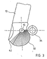
Figur 3- eine Ansicht der Stellkontur am Stellarm und
Figur 4- eine Teilschnittdarstellung eines Längenausgleichselements.
- FIG. 1
- a cross section through a cabinet with a folding lid according to the invention, wherein the folding lid is shown on the one hand in its open position and the other in its closed position;
- FIG. 2
- a perspective view of the Deckelstellers;
- FIG. 3
- a view of the control contour on the actuator arm and
- FIG. 4
- a partial sectional view of a length compensation element.
Der Faltdeckel 8 umfasst ein erstes Deckelelement 9, dass um eine horizontal angeordnete erste Achse 10 schwenkbar am Schrankdeckel 2 befestigt ist. Ferner umfasst der Faltdeckel 8 ein zweites Deckelelement 11, dass um eine horizontal angeordnete zweite Achse 12 schwenkbar mit dem ersten Deckelelement 9 verbunden ist. Der Faltdeckel 8 ist zwischen einer Schließstellung, in der das erste Deckelelement mit 9 und das zweite Deckelelement mit 11 bezeichnet ist, und einer Offenstellung, in der das erste Deckelelement mit 9' und das zweite Deckelelement mit 11' bezeichnet sind, verstellbar. Alle weiteren bewegbaren Bauteile sind im folgenden in der Schließstellung der Faltklappe 8 mit Bezugszeichen ohne Zusatz und in der Offenstellung der Faltklappe 8 mit Bezugszeichen mit einem Strich gekennzeichnet.The folding lid 8 comprises a
Ein Stellarm 13 eines Deckelstellers 14 ist um eine horizontal angeordnete dritte Achse 15 schwenkbar an der Seitenwand 3 befestigt. Der Stellarm 13 ist ferner um eine horizontal angeordnete vierte Achse schwenkbar mit dem zweiten Deckelelement 11 verbunden. Die Funktionsweise des Deckelstellers 14 wird eingehend bei
In der Schwenkposition des Stellarms 13, die der Schließstellung des Faltdeckels 8 entspricht, schließen der wirksame Hebelarm 17 zwischen der ersten Achse 10 und der zweiten Achse 12 und der wirksame Hebelarm 18 zwischen der zweiten Achse 12 und der vierten Achse 16 einen zum Korpus gerichteten Winkel 19 ein, der geringfügig kleiner als 180° ist, so dass die Totpunktstellung in dieser Position nicht überschritten ist. Somit lässt sich mittels eines Griffs 20, der nur geringfügig oberhalb der vierten Achse 16 angeordnet ist, der Faltdeckel 8 vom Korpus 1 abheben und in die Offenstellung überführen.In the pivot position of the
In derjenigen Schwenkposition des Stellarms 13', die der Offenposition des Faltdeckels 8 entspricht, schließen der wirksame Hebelarm 18' zwischen der zweiten Achse 12' und der vierten Achse 16' und der wirksame Hebelarm 21' zwischen der vierten Achse 16' und der dritten Achse 15 einen vom ersten Deckelelement 9' weggerichteten Winkel 22 ein, der geringfügig kleiner ist als 180°. In dieser Stellung sind der Stellarm 13' und das zweite Deckelelement 11' in einer gestreckten Position zueinander angeordnet und haben den oberen Totpunkt des durch die wirksamen Hebelarme gebildeten Drehgelenkgetriebes überschritten. Somit bewirkt die Schwerkraft des Faltdeckels 8, dass der Stellarm 13' in diejenige Schwenkstellung beaufschlagt ist, die der Offenstellung des Faltdeckels 8 entspricht, so dass sich der Faltdeckel 8 nicht selbständig in die Schließstellung bewegen kann. Hierzu ist es erforderlich, dass an dem Griff 20' gezogen wird, um den Faltdeckel 8 aus der oberen Totlage heraus zu bewegen.In that pivotal position of the actuating arm 13 ', which corresponds to the open position of the folding lid 8, close the effective lever arm 18' between the second axis 12 'and the fourth axis 16' and the effective lever arm 21 'between the fourth axis 16' and the third axis 15 a of the first cover member 9 'directed away angle 22 a, which is slightly smaller than 180 °. In this position, the actuating arm 13 'and the second cover member 11' are arranged in an extended position to each other and have exceeded the top dead center of the rotary joint mechanism formed by the effective lever arms. Thus, the gravity of the folding lid 8, that the actuating arm 13 'is acted upon in that pivotal position corresponding to the open position of the folding lid 8, so that the folding lid 8 can not move independently in the closed position. For this purpose, it is necessary that is pulled on the handle 20 'to move the folding lid 8 from the top dead center out.
Um zu gewährleisten, dass das erste Deckelelement 9' in der Offenstellung des Faltdeckels 8 nicht zu weit nach oben über den Schrankdeckel 2 hinausragt und um zu gewährleisten, dass das zweite Deckelelement 11' möglichst nah an das erste Deckelelement 9' herangefaltet wird, sind die erste Achse 10, die zweite Achse 12 (12') und die vierte Achse 16 (16') derart zueinander angeordnet, dass der wirksame Hebelarm 17 (17') zwischen der ersten Achse 10 und der zweiten Achse 12 (12') länger ist als der wirksame Hebelarm 18 (18') zwischen der zweiten Achse 12 (12') und der vierten Achse 16 (16').In order to ensure that the first cover element 9 'in the open position of the folding cover 8 does not protrude too far above the
Zudem sollte gewährleistet sein, dass der Einlegeboden 6 in etwa in Höhe einer gedachten horizontal verlaufenden Mittenebene 23 des Korpus 1 angebracht werden kann. Hierzu ist die dritte Achse 15 oberhalb der Mittenebene 23 angeordnet.In addition, it should be ensured that the
Da der Griff 20 in der Schließstellung des Faltdeckels 8 betrachtet möglichst weit unten am zweiten Deckelelement 11 vorgesehen sein sollte, damit auch Rahmendeckelelemente verwendet werden können, die aus einem Rahmenelement bestehen, welches eine Glasscheibe einfasst, muss auch die vierte Achse 16 möglichst weit unten am zweiten Deckelelement 11 vorgesehen sein. Hierzu ist vorzusehen, daß der wirksame Hebelarm 17 zwischen der ersten Achse 10 und der zweiten Achse 12 länger ist als der Abstand zwischen der zweiten Achse 12 und einer Unterkante 52 des zweiten Deckelelements 11, welche dem ersten Deckelelement 9 entfernt angeordnet ist.Since the
Um trotz der unterschiedlichen Längen der wirksamen Hebel 17, 18 optisch eine symmetrische Teilung des Faltdeckels 8 zu gewährleisten, weist das erste Deckelelement eine erste Blende 24 und das zweite Deckelelement 11 eine zweite Blende 25 auf, die beide in der Schließstellung der Faltklappe betrachtet die gleiche Höhe aufweisen. An einer zum Korpus 1 gerichteten Innenfläche 26 des Deckelelements 9 ist ein Scharnierarm 27 befestigt, der über eine Unterkante 28 der ersten Blende 24 nach unten vorsteht und an einem unteren Ende 29 um die zweite Achse 12 gelenkig an einer zum Korpus 1 gerichteten Innenfläche 46 der zweiten Blende 25 festgelegt ist. Der Abstand zwischen der Unterkante 28 und der zweiten Achse 12 entspricht in etwa dem Abstand einer Oberkante 30 der zweiten Blende 25 zur zweiten Achse 12.In order to ensure optically symmetrical division of the folding lid 8 despite the different lengths of the
Bei einer Standardhöhe des Korpus von 720 mm ist die dritte Achse 15 vorzugsweise etwa 289 mm von der Innenfläche des Schrankdeckels 2 und bei geschlossener Faltklappe etwa 78 mm von der Innenfläche 26 des ersten Deckelelements 9 entfernt angeordnet. Bei einer Standardhöhe von 600 mm betragen diese Werte etwa 223 mm vom Schrankdeckel 2 und 63 mm vom ersten Deckelelement 9.At a standard height of the body of 720 mm, the
Bei beiden Standardhöhen ist bei identischen Höhen der ersten Blende 24 und der zweiten Blende 25 die zweite Achse 12 bei geschlossener Faltklappe etwa 52 mm von der Unterkante 28 der ersten Blende 24 nach unten versetzt angeordnet. Die vierte Achse 16 ist 30 mm von der Innenfläche 46 des zweiten Deckelelements und etwa 22 mm von der Oberfläche des Schrankbodens 4 entfernt.At both standard heights, the
Der Deckelsteller 14 wird im folgenden anhand der
Der Stellarm 13 ist in einem Gehäuse 31 des Deckelstellers 14 um die dritte Achse 15 schwenkbar gelagert, wobei das Gehäuse 31 fest mit der Seitenwand 3 des Korpus 1 verbunden ist. Der Stellarm 13 weist eine Stellkontur 32 auf, die in Form einer Kurve um die dritte Achse 15 dargestellt ist.The
In dem Gehäuse 31 ist ein Stellschieber 33 linear verschiebbar geführt. Der Stellschieber 33 weist eine Rolle 34 auf, die um eine Drehachse 35, welche parallel zur dritten Achse 15 angeordnet ist, drehbar am Stellschieber 33 gelagert. Mit einer Außenumfangsfläche ist die Rolle 34 in Anlage zur Stellkontur 32. Federn 50 beaufschlagen den Stellschieber 33 und damit die Rolle 34 gegen die Stellkontur 32. Die Federmittel stützen sich einerseits gegen den Stellschieber 33 und andererseits gegen ein Stützlager 36 ab, welches linear verschiebbar im Gehäuse 31 gelagert ist. Das Stützlager 36 ist gegen eine Lagerfläche 37 eines Widerlagers 38 abgestützt, wobei das Widerlager 38 um eine Drehachse 39 drehbar im Gehäuse 31 gelagert ist und wobei die Lagerfläche 37 einen veränderlichen Abstand zur Drehachse 39 des Widerlagers 38 aufweist, so dass das Stützlager 36 in einem veränderbarem Abstand zur dritten Achse 15 im Gehäuse 31 gehalten ist. Die Lagerfläche 37 ist schneckenförmig ausgebildet und weist radiale Rastvertiefungen auf, in die eine Rastnase 41 des Stützlagers 36 einrastet, um zu verhindern, dass das Widerlager 38 unbeabsichtigt gedreht wird.In the
Die Stellkontur 32 des Stellarms 13 ist derart ausgebildet, dass der radiale Abstand der Stellkontur 32 zur dritten Achse 15 im Kontaktbereich zwischen dem Stellschieber 33, d. h. der Rolle 34, und der Stellkontur 32 über einen Schwenkweg ausgehend von einer ersten Schwenkposition des Stellarms 13, die der Offenstellung des Faltdeckels 8 entspricht, über einen Winkelweg des Stellarms 13 zu einer Zwischenposition des Stellarms 13, die einer Stellung des Faltdeckels 8 nahe der Schließstellung zwischen der Offenstellung und der Schließstellung entspricht, zunimmt. Somit ist gewährleistet, dass der Stellarm 13 über den größten Winkelweg mit einer Kraft beaufschlagt ist, die ein Moment zur oberen Position, die der Offenstellung des Faltdeckels 8 entspricht, erzeugt. Über den Winkelweg ausgehend von der Zwischenstellung bis zu der Schwenkstellung, die der Schließstellung des Faltdeckels 8 entspricht, weist die Stellkontur eine Abflachung auf, über deren Verlauf in der der radiale Abstand zur dritten Achse 15 abnimmt. Somit wird über diesen Schwenkweg ein Drehmoment erzeugt, welches den Stellarm 13 zu derjenigen Schwenkstellung beaufschlagt, die der Schließstellung des Faltdeckels 8 entspricht. Die Stellkontur 32 ist derart ausgebildet, dass das erzeugte Drehmoment in jeder Schwenkstellung des Stellarms 13 demjenigen Gegenmoment entspricht, welches durch die Gewichtskraft des Faltdeckels 8 insgesamt erzeugt wird, so dass der Faltdeckel 8 in jeder Stellung zwischen der Offenstellung und der Zwischenstellung gehalten wird.The
Das Längenausgleichselement 43 dient dazu, Fertigungsungenauigkeiten auszugleichen, sowie Änderungen hinsichtlich des Abstandes der vierten Achse 16 zur ersten Achse 10 auszugleichen. Änderungen können sich dadurch ergeben, dass das erste Deckelelement 9 mittels eines einstellbaren Scharniers 51 am Schrankdeckel 2 schwenkbar befestigt ist. Somit wird vermieden, dass bei Einstellung des Scharniers 51 auch eine Einstellung des Anlenkpunktes des Stellarmes 13 am zweiten Deckelelement 11 erforderlich ist.The
Zudem wirkt aufgrund der Feder 49 eine Federkraft vertikal nach unten auf das zweite Deckelelement 11, wenn sich der Faltdeckel 8 in seiner Schließposition befindet. Hierdurch wird ein Moment erzeugt, durch das der Faltdeckel 8 an den Korpus 1 angezogen wird.In addition, due to the
- 11
- Korpuscorpus
- 22
- Schrankdeckelcabinet cover
- 33
- SeitenwandSide wall
- 44
- Schrankbodencabinet base
- 55
- Rückwandrear wall
- 66
- Einlegebodenshelf
- 77
- Öffnungopening
- 88th
- Faltdeckelfolding cover
- 9, 9'9, 9 '
- erstes Deckelelementfirst cover element
- 1010
- erste Achsefirst axis
- 11, 11'11, 11 '
- zweites Deckelelementsecond cover element
- 12, 12'12, 12 '
- zweite Achsesecond axis
- 13, 13'13, 13 '
- Stellarmactuating arm
- 1414
- Deckelstellercover plate
- 1515
- dritte Achsethird axis
- 16, 16'16, 16 '
- vierte Achsefourth axis
- 17, 17'17, 17 '
- Hebelarmlever arm
- 18, 18'18, 18 '
- Hebelarmlever arm
- 1919
- Winkelangle
- 20, 20'20, 20 '
- GriffHandle
- 21, 21'21, 21 '
- Hebelarmlever arm
- 2222
- Winkelangle
- 2323
- Mittenebenemidplane
- 24, 24'24, 24 '
- erste Blendefirst aperture
- 25, 25'25, 25 '
- Zweite BlendeSecond aperture
- 26, 26'26, 26 '
- Innenflächepalm
- 27, 27'27, 27 '
- Scharnierarmhinge
- 28, 28'28, 28 '
- Unterkante .Lower edge.
- 2929
- unteres Endelower end
- 3030
- Oberkantetop edge
- 3131
- Gehäusecasing
- 3232
- Stellkontursetting contour
- 3333
- Stellschieberlock slider
- 3434
- Rollerole
- 3535
- Drehachseaxis of rotation
- 3636
- Stützlagersupport bearings
- 3737
- Lagerflächestorage area
- 3838
- Widerlagerabutment
- 3939
- Drehachseaxis of rotation
- 4040
- Rastvertiefungenlocking recesses
- 4141
- Rastnaselocking lug
- 4242
- Abflachungflattening
- 4343
- LängenausgleichselementLength compensation element
- 4444
- Basiselementbase element
- 4545
- Schiebeelementsliding element
- 4646
- Innenflächepalm
- 4747
- Führungsnutguide
- 4848
- Führungsansatzleadership approach
- 4949
- Federfeather
- 5050
- Federfeather
- 5151
- Scharnierhinge
- 52, 52'52, 52 '
- Unterkantelower edge
Claims (12)
- Folding lid for a cabinet, especially a wall-mounted cabinet, e.g. for kitchen furniture or office furniture, which is arranged opening upwards and is displaceable between an open position and a closed position,
comprising
a first lid element (9), which is attachable on a cabinet lid (2) of the corpus (1) pivotably around a horizontally arranged first axis (10),
a second lid element (11), which is connected to the first lid element (9) pivotably around a second axis (12) arranged parallel to the first axis (10),
a lid stay (14) with a spring-loaded positioning arm (13),
which is attachable on a side wall (3) of the corpus (1) pivotably around a third axis (15) arranged parallel to the first axis (10) and
which is connected to the second lid element (11) pivotably around a horizontally arranged fourth axis (16),
characterised in
that for the spring-loaded positioning arm (13) a spring-loaded setting contour (32), which is represented in the form of a curve around the third axis, is provided on the positioning arm (13), wherein the radial distance of the setting contour (32) relative to the third axis (15) decreases at least partially, starting from an intermediate position of the positioning arm (13), which corresponds to a position of the folding lid (8) between the open position and the closed position, over an angular path of the positioning arm (13) to a second pivot position, which corresponds to the open position of the folding lid (8), and the setting contour (32) is formed in this area such, that the produced torque in any pivot position of the positioning arm (13) corresponds to the counter torque, which is produced by the gravity force of the folding lid (8), so that the lid stay (14) is loaded at least over the pivot path from the intermediate position towards the open position of the folding lid (8) in the direction towards the open position by a torque, which is designed that large in any pivot position between the intermediate position and the open position, that the folding lid (8) is held. - Folding lid according to claim 1,
characterised in
that the distance between the first axis (10) and the second axis (12) is larger than the distance between the second axis (12) and the fourth axis (16) and
that in the closed position of the folding lid (8) the third axis (15) is arranged above an imaginary horizontal centre axis (23) of the folding lid (8). - Folding lid according to claim 2,
characterised in
that the distance between the first axis (10) and the second axis (12) is larger than the distance between the second axis (12) and a lower edge (52) of the second lid element (11), which is arranged distanced from the first lid element (9). - Folding lid according to one of claims 1 to 3,
characterised in
that in the open position of the folding lid (8') the fourth axis (16') is arranged off-set in a direction towards the first lid element (9') from a plane, which contains the second axis (12') and the third axis (15). - Folding lid according to one of claims 1 to 4,
characterised in
that the first lid element (9) has a first panel (24) and the second lid element (11) has a second panel (25), wherein the first panel (24) and the second panel (25) have the same height, when seen in the closed position of the folding lid (8),
that at least one hinge arm (27) is provided, which is attached on an inner face (26) of the first lid element (9) directed towards the corpus (1) and which projects beyond a lower edge (28) of the first lid element (9) downwards and is attached at a lower end (29) pivotably around the second axis (12) on an inner face (46) of the second lid element (11) facing towards the corpus (1),
wherein the distance between the lower edge (28) of the first lid element (9) and the second axis (12) corresponds more or less to the distance between the upper edge (3) of the second lid element (11) and the second axis (12). - Folding lid according to one of claims 1 to 5,
characterised in
that the lid stay (14) has a housing (31), which is connectable to the side wall (3) of the corpus (1) and in which the positioning arm (13) is supported pivotably around the third axis (15),
that a setting slider (33) is provided, which is guided linearly displaceable in the housing (31) and which is acted upon by the spring means radially into abutment with the setting contour (32) of the positioning arm (13). - Folding lid according to claim 6,
characterised in
that the radial distance of the setting contour (32) to the third axis (15) is constant or increases in the contact area between the setting slider (33) and the setting contour (32), starting from a first pivoting position of the positioning arm (13), which corresponds to the closed position of the folding lid (8), over an angular path of the positioning arm (13) towards an intermediate position between the first pivoting position and the second pivoting position. - Folding lid according to one of claims 6 or 7,
characterised in
that the setting slider (33) is supported with a roller (34), which is supported rotatably on the setting slider (33), on the setting contour (32). - Folding lid according to one of claims 6 to 8,
characterised in
that a support bearing (36) is provided, which is held with a variable distance to the third axis (15) in the housing (31), and
that the spring means are supported on the setting slider (33) and on the support bearing (36). - Folding lid according to claim 9,
characterised in
that the support bearing (36) is supported on a bearing face (37) of an abutment (38), which is supported rotatably around a rotational axis (39) in the housing (31), wherein the bearing face (37) has in circumferential direction a variable distance to the rotational axis (39). - Folding lid according to claim 10,
characterised in
that the bearing face (37) is formed worm-like. - Folding lid according to one of claims 1 to 11,
characterised in
that a length compensation element (43) is provided, which comprises a base element (44), which is connected rigidly to the second lid element (11) and which comprises a sliding element (45), which, when seen in vertical direction, is guided displaceably in the closed position of the folding lid (8) between a first position, arranged close to the second axis (12), and a second position, which is arranged distanced from the second axis (12), relative to the base element (44) and guided in the same and is acted upon by spring means (49) towards the first position.
Applications Claiming Priority (2)
| Application Number | Priority Date | Filing Date | Title |
|---|---|---|---|
| DE10145856A DE10145856B4 (en) | 2001-09-17 | 2001-09-17 | folding cover |
| DE10145856 | 2001-09-17 |
Publications (2)
| Publication Number | Publication Date |
|---|---|
| EP1296011A1 EP1296011A1 (en) | 2003-03-26 |
| EP1296011B1 true EP1296011B1 (en) | 2009-06-17 |
Family
ID=7699362
Family Applications (1)
| Application Number | Title | Priority Date | Filing Date |
|---|---|---|---|
| EP02015475A Expired - Lifetime EP1296011B1 (en) | 2001-09-17 | 2002-07-12 | Bi-fold lid |
Country Status (10)
| Country | Link |
|---|---|
| US (1) | US7240974B2 (en) |
| EP (1) | EP1296011B1 (en) |
| JP (1) | JP4006401B2 (en) |
| KR (1) | KR100624631B1 (en) |
| CN (1) | CN100342111C (en) |
| AT (1) | ATE434106T1 (en) |
| CA (1) | CA2460641A1 (en) |
| DE (2) | DE10145856B4 (en) |
| ES (1) | ES2331057T3 (en) |
| WO (1) | WO2003025323A1 (en) |
Families Citing this family (78)
| Publication number | Priority date | Publication date | Assignee | Title |
|---|---|---|---|---|
| DE10323698B3 (en) * | 2003-05-22 | 2005-02-10 | Huwil-Werke Gmbh Möbelschloss- Und Beschlagfabriken | cover plate |
| US8096455B2 (en) | 2003-10-09 | 2012-01-17 | Thule Sweden Ab | Single force strut for dual sided cargo box |
| ITMI20031950A1 (en) * | 2003-10-10 | 2005-04-11 | Agostino Ferrari Spa | HINGE GROUP FOR THE ARTICULATED CONNECTION OF A VERTICAL OPENING PANEL WITH A FURNITURE ELEMENT |
| AT413418B (en) * | 2004-02-09 | 2006-02-15 | Blum Gmbh Julius | CABINET FURNITURE |
| AT7499U1 (en) * | 2004-02-09 | 2005-04-25 | Blum Gmbh Julius | STAND ARM DRIVE FOR FLAP FLAKES |
| AT7500U1 (en) * | 2004-02-09 | 2005-04-25 | Blum Gmbh Julius | STAND ARM DRIVE FOR FLAP FLAKES |
| DE102004019784B3 (en) * | 2004-04-23 | 2005-12-29 | Hetal-Werke Franz Hettich Gmbh & Co | Faltklappenbeschlag |
| ITBO20040344A1 (en) * | 2004-05-31 | 2004-08-31 | Nuova Star Spa | HINGE FOR DOORS OR DOORS |
| DE202005021541U1 (en) * | 2004-07-14 | 2008-08-28 | Julius Blum Gmbh | Actuation mechanism for a pivotally mounted actuator arm |
| AT414257B (en) | 2004-10-12 | 2006-10-15 | Blum Gmbh Julius | HOLDING AND ADJUSTMENT DEVICE FOR MOVING FURNITURE PARTS |
| AT502938A1 (en) * | 2004-11-18 | 2007-06-15 | Blum Gmbh Julius | ACTUATOR FOR MOVING A FLAP OF A FURNITURE |
| ITMI20050181A1 (en) * | 2005-02-09 | 2006-08-10 | Effegi Brevetti Srl | OPENING-CLOSING DEVICE OF A FURNITURE DOOR OF A FURNITURE |
| AT502944A1 (en) * | 2005-03-21 | 2007-06-15 | Blum Gmbh Julius | FURNITURE WITH A FURNITURE BASKET AND AT LEAST ONE HIGH FLOATING FLAP |
| DE102005018552A1 (en) * | 2005-04-20 | 2006-11-02 | Huwil-Werke Gmbh Möbelschloss- Und Beschlagfabriken | retaining element |
| AT502620B1 (en) | 2005-10-12 | 2011-11-15 | Blum Gmbh Julius | FLAP FITTING |
| US7665692B2 (en) * | 2005-10-28 | 2010-02-23 | Airbus | Baggage bin door and baggage bin |
| DE202006015190U1 (en) * | 2006-10-04 | 2006-11-23 | Arturo Salice S.P.A., Novedrate | Lift device for two-part folding flap has double-armed lever and hinge arm which moves relative to the hinge socket in which it is mounted about eccentrics in different directions |
| ITMI20062235A1 (en) * | 2006-11-22 | 2008-05-23 | Agostino Ferrari Spa | ARTICULATED QUADRILATERO HINGE ASSEMBLY WITH ADAPTABLE STABILIZER BAR FOR VERTICAL MOVEMENT DOORS |
| US20080136198A1 (en) * | 2006-12-07 | 2008-06-12 | Kidkraft, Lp. | Adjustable bracing device for holding an openable case in an opened position |
| ITMI20070282A1 (en) * | 2007-02-15 | 2008-08-16 | Effegi Brevetti Srl | OPENING-CLOSING DEVICE FOR A DOOR WITH DOUBLE UPHOLSTERY OF A FURNITURE |
| AT505126B1 (en) * | 2007-05-07 | 2009-05-15 | Blum Gmbh Julius | FLAP DRIVE SYSTEM |
| AT505879A1 (en) * | 2007-09-28 | 2009-04-15 | Blum Gmbh Julius | ADJUSTMENT MECHANISM FOR A SWIVELED STACKING ARM |
| JP4732417B2 (en) * | 2007-10-03 | 2011-07-27 | スガツネ工業株式会社 | Movable holder |
| AT506196B1 (en) * | 2007-12-19 | 2010-10-15 | Blum Gmbh Julius | ADJUSTMENT MECHANISM FOR MOVING A HIGH-MOVABLE FLAP OF A FURNITURE |
| DE102008005463A1 (en) * | 2008-01-21 | 2009-07-23 | Huwil-Werke Gmbh Möbelschloss- Und Beschlagfabriken | Retaining element for adjusting a lid of a piece of furniture |
| AT14082U1 (en) * | 2008-05-15 | 2015-04-15 | Blum Gmbh Julius | furniture drive |
| DE102008025265B4 (en) | 2008-05-27 | 2015-04-02 | HUWIL Bútoripari és Üzletberendezési Rendszerek kft | folding cover |
| AT10668U1 (en) * | 2008-08-29 | 2009-08-15 | Blum Gmbh Julius | HOUSING FOR AT LEAST PARTIAL RECORDING OF A FURNITURE FITTING |
| AT507279A1 (en) * | 2008-08-29 | 2010-03-15 | Blum Gmbh Julius | DRIVE DEVICE FOR A FURNITURE FLAP |
| KR100970472B1 (en) * | 2008-12-12 | 2010-07-16 | 주식회사 다이아벨 | Swing Hinge Module |
| RU2537836C2 (en) * | 2009-05-13 | 2015-01-10 | Юлиус Блум Гмбх | Drive for furniture wing capable of turning into open position |
| WO2010129981A1 (en) * | 2009-05-13 | 2010-11-18 | Julius Blum Gmbh | Flap drive system |
| AT508529A1 (en) * | 2009-07-28 | 2011-02-15 | Blum Gmbh Julius | ACTUATOR FOR A MOVABLE FURNITURE PART |
| EP2559835A4 (en) * | 2010-04-16 | 2017-12-20 | Sugatsune Kogyo CO., LTD. | Door opening/closing apparatus |
| DE202010015094U1 (en) * | 2010-11-04 | 2012-02-06 | Grass Gmbh | Furniture fitting and furniture |
| AT510984B1 (en) * | 2011-02-22 | 2012-08-15 | Blum Gmbh Julius | ACTUATOR FOR MOVING A FURNITURE FLAP |
| DE102011054280B4 (en) | 2011-10-07 | 2013-06-06 | HUWIL Bútoripari és Üzletberendezési Rendszerek kft | Cover plate for a folding lid |
| ES2724779T3 (en) * | 2012-01-30 | 2019-09-16 | Blum Gmbh Julius | Servo drive for a flip top of a piece of furniture |
| AT512156B1 (en) * | 2012-05-25 | 2013-06-15 | Blum Gmbh Julius | Arrangement for moving a movable furniture part |
| CN102953650B (en) * | 2012-12-03 | 2015-03-04 | 煤炭科学技术研究院有限公司 | Gravity type combined explosion door |
| AT513387B1 (en) * | 2013-02-08 | 2014-04-15 | Blum Gmbh Julius | Actuator for moving a movable furniture part |
| AT514050A1 (en) * | 2013-03-04 | 2014-09-15 | Blum Gmbh Julius | Actuator for a furniture flap |
| AT514585B1 (en) * | 2013-08-30 | 2015-02-15 | Blum Gmbh Julius | Actuator for movable furniture parts |
| AT515492B1 (en) * | 2014-03-14 | 2020-01-15 | Blum Gmbh Julius | Actuator for furniture flaps |
| DE102014113970B4 (en) * | 2014-09-26 | 2016-08-18 | Samet Kalip Ve Maden Esya San. Ve Tic. A.S. | hinge |
| AT515661B1 (en) | 2014-11-21 | 2015-11-15 | Blum Gmbh Julius | Actuator for movable furniture parts |
| AT516282B1 (en) | 2014-11-26 | 2016-04-15 | Blum Gmbh Julius | Arrangement for spreading at least two hingedly connected door leaves |
| AT516784B1 (en) * | 2015-02-13 | 2017-02-15 | Blum Gmbh Julius | Furniture |
| US10590688B2 (en) * | 2015-02-17 | 2020-03-17 | Arturo Salice S.P.A. | Lifting system for leaves of furniture |
| DE102015102387A1 (en) * | 2015-02-19 | 2016-08-25 | Paul Hettich Gmbh & Co. Kg | Sliding tilt mechanism of a storage of a household appliance and household appliance |
| DE102015102393A1 (en) * | 2015-02-19 | 2016-08-25 | Hettich Holding Gmbh & Co. Ohg | swivel fitting |
| CN104790794B (en) * | 2015-04-16 | 2016-08-24 | 伍志勇 | Hoisting capacity governor motion for furniture tilt-up door |
| WO2016174076A1 (en) * | 2015-04-30 | 2016-11-03 | Arturo Salice S.P.A. | Hinge for furniture leaves that swing about at least one horizontal axis |
| AT517343B1 (en) * | 2015-06-29 | 2017-01-15 | Blum Gmbh Julius | Ejector for a folding door or folding-sliding door |
| DE202015105233U1 (en) * | 2015-10-05 | 2017-01-09 | Grass Gmbh & Co. Kg | Hinge for a movable furniture part attached to a body of a piece of furniture |
| US10221058B2 (en) * | 2015-10-09 | 2019-03-05 | Cornelius, Inc. | Maneuverable service door for beverage dispensing machines |
| ITUB20156022A1 (en) * | 2015-11-30 | 2017-05-30 | Leandro Cappellotto | MOVEMENT MECHANISM OF FURNITURE DOORS |
| AT16381U1 (en) * | 2016-02-26 | 2019-08-15 | Blum Gmbh Julius | Deputy arm drive |
| AT16333U1 (en) * | 2016-03-11 | 2019-07-15 | Blum Gmbh Julius | Actuator for driving a movably mounted furniture part |
| AT518535B1 (en) * | 2016-04-28 | 2017-11-15 | Blum Gmbh Julius | furniture drive |
| IT201600098088A1 (en) * | 2016-09-30 | 2018-03-30 | Salice Arturo Spa | Control device for a lifting system and lifting system for furniture doors. |
| DE102017107565A1 (en) * | 2017-04-07 | 2018-10-11 | Hettich-Heinze Gmbh & Co. Kg | Furniture fitting for a combined sliding and pivoting movement of a multi-part door and furniture with such a furniture fitting |
| AU2018254677B2 (en) * | 2017-04-18 | 2024-03-14 | Hettich-Oni Gmbh & Co. Kg | Furniture board having a flap fitting and carcass and furniture item having such a furniture board |
| IT201700044196A1 (en) * | 2017-04-21 | 2018-10-21 | Effegi Brevetti Srl | MOVEMENT MECHANISM OF A FURNITURE DOOR |
| AT519898B1 (en) * | 2017-05-11 | 2019-12-15 | Blum Gmbh Julius | Fitting for a folding door |
| AT519674B1 (en) * | 2017-05-11 | 2018-09-15 | Blum Gmbh Julius | Ejector for a folding door |
| EP3625417B1 (en) * | 2017-05-15 | 2021-08-25 | Samet Kalip Ve Madeni Esya San. Ve Tic. A.S. | Length-adjustable control arm |
| CN107842267B (en) * | 2017-11-17 | 2023-05-02 | 广东东泰五金精密制造有限公司 | Adjustable movable positioning structure for folding door of furniture |
| ES2770375T3 (en) | 2018-01-31 | 2020-07-01 | Flap Competence Center Kft | Lid positioner for a piece of furniture |
| DE202018102086U1 (en) * | 2018-04-17 | 2019-07-18 | Grass Gmbh | Articulated lever for a device for moving a furniture part received on a furniture carcass of a piece of furniture |
| CN108505863B (en) * | 2018-05-22 | 2023-11-17 | 广东东箭汽车科技股份有限公司 | Door plant buffering booster unit and car |
| EP3581435B1 (en) * | 2018-06-13 | 2021-03-17 | Thule Sweden AB | Vehicle carrier box |
| CN109083529B (en) * | 2018-09-06 | 2023-09-26 | 江苏玖星精密科技集团有限公司 | Refrigerator door closing device with arbitrary hovering function |
| IT201800009883A1 (en) * | 2018-10-30 | 2020-04-30 | Effegi Brevetti Srl | MECHANISM FOR HANDLING A FLAP DOWNWARDS |
| AT522287A1 (en) * | 2019-03-20 | 2020-10-15 | Blum Gmbh Julius | Lead management |
| ES2882801T3 (en) * | 2019-04-02 | 2021-12-02 | Flap Competence Center Kft | Flap hardware |
| DE102019113337B4 (en) * | 2019-05-20 | 2022-07-14 | Samet Kalip Ve Maden Esya San. Ve Tic. A.S. | furniture fitting |
| KR102140551B1 (en) * | 2020-01-03 | 2020-08-03 | 서원코리아 주식회사 | Multi-link door hinge |
Citations (1)
| Publication number | Priority date | Publication date | Assignee | Title |
|---|---|---|---|---|
| EP1148200A2 (en) * | 2000-04-19 | 2001-10-24 | Hetal-Werke Franz Hettich GmbH & Co. | Flap holder |
Family Cites Families (17)
| Publication number | Priority date | Publication date | Assignee | Title |
|---|---|---|---|---|
| US472483A (en) * | 1892-04-05 | Lock-hinge | ||
| US2483947A (en) * | 1947-10-18 | 1949-10-04 | Turner Alonzo Robert | Cover lift hinge |
| US2656563A (en) * | 1950-07-18 | 1953-10-27 | Robert Trent Jones | Counterbalanced hinge |
| DE1529652C2 (en) * | 1961-10-22 | 1977-03-24 | Alno Möbelwerke GmbH Co. KG, 7798 Pfuüendorf | Foldable cabinet door |
| US3224494A (en) * | 1962-04-30 | 1965-12-21 | Cons Electronics Ind | Door |
| DE2020966A1 (en) * | 1970-04-29 | 1971-11-25 | Stanley Works Gmbh | Fitting for a folding door that opens upwards, especially for kitchen hangers |
| FR2647733B1 (en) * | 1989-06-06 | 1991-09-20 | Rockwell Abs France | MIRROR CASSETTE FOR SUN VISOR, ESPECIALLY IN AN AUTOMOBILE INTERIOR |
| CN2138180Y (en) * | 1992-09-10 | 1993-07-14 | 赵晖 | Door shutter with springs |
| JP2568275Y2 (en) * | 1993-07-13 | 1998-04-08 | スガツネ工業株式会社 | Door horizontal holding device for flap door |
| US5513420A (en) * | 1994-05-04 | 1996-05-07 | Tyler Refrigeration Corporation | Hinge assembly for refrigerated display cabinet |
| DE29604354U1 (en) * | 1996-03-08 | 1996-06-05 | Salice Arturo Spa | Retaining fitting for a flap hinged to a top wall of a cabinet about a horizontal pivot axis |
| TW334493B (en) * | 1996-05-14 | 1998-06-21 | Sugatsune Kogyo | Damper for opening or closing a door |
| IT1286983B1 (en) * | 1996-05-29 | 1998-07-24 | Antonio Cittadini | SHUTTER FOR WINDOWS AND FOLDING FOLDING DOORS |
| DE29808185U1 (en) * | 1998-05-06 | 1998-08-27 | Salice Arturo Spa | Furniture with a body part that can be closed by a double-leaf sliding door |
| DE19918823C1 (en) * | 1999-04-26 | 2000-07-20 | Huwil Werke Gmbh | Furniture flap setting mechanism has two arms on a swing axis to move the flap out of the vertical closed setting together with a friction system to hold it in the required orientation and a spring loading on the arms |
| JP3339837B2 (en) * | 1999-05-28 | 2002-10-28 | スガツネ工業株式会社 | Overhead cabinet with pivoting door |
| DE20100662U1 (en) | 2001-01-15 | 2001-04-19 | Salice Arturo Spa | Lifting device for a two-leaf folding flap |
-
2001
- 2001-09-17 DE DE10145856A patent/DE10145856B4/en not_active Expired - Fee Related
-
2002
- 2002-07-12 ES ES02015475T patent/ES2331057T3/en not_active Expired - Lifetime
- 2002-07-12 AT AT02015475T patent/ATE434106T1/en active
- 2002-07-12 EP EP02015475A patent/EP1296011B1/en not_active Expired - Lifetime
- 2002-07-12 DE DE50213611T patent/DE50213611D1/en not_active Expired - Lifetime
- 2002-07-13 CN CNB028227808A patent/CN100342111C/en not_active Expired - Lifetime
- 2002-07-13 JP JP2003528934A patent/JP4006401B2/en not_active Expired - Lifetime
- 2002-07-13 WO PCT/EP2002/007817 patent/WO2003025323A1/en active Application Filing
- 2002-07-13 CA CA002460641A patent/CA2460641A1/en not_active Abandoned
- 2002-07-13 US US10/489,667 patent/US7240974B2/en not_active Expired - Lifetime
- 2002-07-13 KR KR1020047003886A patent/KR100624631B1/en active IP Right Grant
Patent Citations (1)
| Publication number | Priority date | Publication date | Assignee | Title |
|---|---|---|---|---|
| EP1148200A2 (en) * | 2000-04-19 | 2001-10-24 | Hetal-Werke Franz Hettich GmbH & Co. | Flap holder |
Also Published As
| Publication number | Publication date |
|---|---|
| US20040239213A1 (en) | 2004-12-02 |
| CN100342111C (en) | 2007-10-10 |
| ES2331057T3 (en) | 2009-12-21 |
| DE50213611D1 (en) | 2009-07-30 |
| KR20040060925A (en) | 2004-07-06 |
| DE10145856A1 (en) | 2003-04-17 |
| US7240974B2 (en) | 2007-07-10 |
| JP2005503506A (en) | 2005-02-03 |
| EP1296011A1 (en) | 2003-03-26 |
| CA2460641A1 (en) | 2003-03-27 |
| WO2003025323A8 (en) | 2004-05-27 |
| JP4006401B2 (en) | 2007-11-14 |
| CN1589360A (en) | 2005-03-02 |
| WO2003025323A1 (en) | 2003-03-27 |
| KR100624631B1 (en) | 2006-09-19 |
| ATE434106T1 (en) | 2009-07-15 |
| DE10145856B4 (en) | 2005-09-08 |
Similar Documents
| Publication | Publication Date | Title |
|---|---|---|
| EP1296011B1 (en) | Bi-fold lid | |
| EP1507944B1 (en) | Lid-positioning device | |
| EP1766173B1 (en) | Piece of furniture with actuating mechanism and swivel-mounted actuating arm | |
| DE102008025265B4 (en) | folding cover | |
| EP2096360B1 (en) | Household device door | |
| DE102008005463A1 (en) | Retaining element for adjusting a lid of a piece of furniture | |
| DE19918823C1 (en) | Furniture flap setting mechanism has two arms on a swing axis to move the flap out of the vertical closed setting together with a friction system to hold it in the required orientation and a spring loading on the arms | |
| EP0065109B1 (en) | Hinge | |
| EP1766172A1 (en) | Raising device for a two-leaf folding flap | |
| DE202010015094U1 (en) | Furniture fitting and furniture | |
| EP2309086B1 (en) | Holding element for adjusting a cover of a piece of furniture | |
| WO2007134348A1 (en) | Cable shutter for a table | |
| DE10203269A1 (en) | Flap has a lever (8) with a force transfer unit (19)with an adjustable lever arm and gas pressure spring (7) with actuating part (9) so that the angle under the gas pressure spring | |
| EP0908592B1 (en) | Door lifting device | |
| DE2648085A1 (en) | Hinge for overhead cabinet flap - has spring adjusted by changing pivot point for different flap weights | |
| WO2005075777A1 (en) | Actuating-arm drive for cupboard doors | |
| EP3326491A1 (en) | Fitting for the mobile positioning of a shelf board in a corner cupboard by means of a cogged wheel | |
| DE20122310U1 (en) | Folding cover door for kitchen cupboard has two cover door panels pivoted together and mounted on support strut | |
| EP1581712B1 (en) | Mounting unit for a window or a door | |
| DE2646371A1 (en) | Swing=out flap for kitchen cabinet - has sliding hinges connecting flap with cabinet by set of link arms | |
| DE202014105721U1 (en) | damping hinge | |
| EP3623559B1 (en) | Lid fitting for swingable mounting of a lid to a furniture unit | |
| EP2096361B1 (en) | Household device door and method for operating same | |
| EP3192956A1 (en) | Lid positioning device | |
| EP2801687A1 (en) | Holding assembly for a cabinet comprising a body and a mobile folding cover on the same |
Legal Events
| Date | Code | Title | Description |
|---|---|---|---|
| PUAI | Public reference made under article 153(3) epc to a published international application that has entered the european phase |
Free format text: ORIGINAL CODE: 0009012 |
|
| AK | Designated contracting states |
Kind code of ref document: A1 Designated state(s): AT BE BG CH CY CZ DE DK EE ES FI FR GB GR IE IT LI LU MC NL PT SE SK TR Designated state(s): AT BE BG CH CY CZ DE DK EE ES FI FR GB GR IE IT LI LU MC NL PT SE SK TR |
|
| AX | Request for extension of the european patent |
Extension state: AL LT LV MK RO SI |
|
| 17P | Request for examination filed |
Effective date: 20030724 |
|
| AKX | Designation fees paid |
Designated state(s): AT BE BG CH CY CZ DE DK EE ES FI FR GB GR IE IT LI LU MC NL PT SE SK TR |
|
| AXX | Extension fees paid |
Extension state: RO Payment date: 20030724 Extension state: SI Payment date: 20030724 |
|
| 17Q | First examination report despatched |
Effective date: 20040831 |
|
| 17Q | First examination report despatched |
Effective date: 20040831 |
|
| GRAP | Despatch of communication of intention to grant a patent |
Free format text: ORIGINAL CODE: EPIDOSNIGR1 |
|
| GRAS | Grant fee paid |
Free format text: ORIGINAL CODE: EPIDOSNIGR3 |
|
| GRAA | (expected) grant |
Free format text: ORIGINAL CODE: 0009210 |
|
| AK | Designated contracting states |
Kind code of ref document: B1 Designated state(s): AT BE BG CH CY CZ DE DK EE ES FI FR GB GR IE IT LI LU MC NL PT SE SK TR |
|
| AX | Request for extension of the european patent |
Extension state: RO SI |
|
| REG | Reference to a national code |
Ref country code: GB Ref legal event code: FG4D Free format text: NOT ENGLISH |
|
| REG | Reference to a national code |
Ref country code: CH Ref legal event code: EP |
|
| REG | Reference to a national code |
Ref country code: IE Ref legal event code: FG4D Free format text: LANGUAGE OF EP DOCUMENT: GERMAN |
|
| REF | Corresponds to: |
Ref document number: 50213611 Country of ref document: DE Date of ref document: 20090730 Kind code of ref document: P |
|
| REG | Reference to a national code |
Ref country code: SE Ref legal event code: TRGR |
|
| PG25 | Lapsed in a contracting state [announced via postgrant information from national office to epo] |
Ref country code: FI Free format text: LAPSE BECAUSE OF FAILURE TO SUBMIT A TRANSLATION OF THE DESCRIPTION OR TO PAY THE FEE WITHIN THE PRESCRIBED TIME-LIMIT Effective date: 20090617 |
|
| NLV1 | Nl: lapsed or annulled due to failure to fulfill the requirements of art. 29p and 29m of the patents act | ||
| REG | Reference to a national code |
Ref country code: ES Ref legal event code: FG2A Ref document number: 2331057 Country of ref document: ES Kind code of ref document: T3 |
|
| REG | Reference to a national code |
Ref country code: IE Ref legal event code: FD4D |
|
| PG25 | Lapsed in a contracting state [announced via postgrant information from national office to epo] |
Ref country code: IE Free format text: LAPSE BECAUSE OF FAILURE TO SUBMIT A TRANSLATION OF THE DESCRIPTION OR TO PAY THE FEE WITHIN THE PRESCRIBED TIME-LIMIT Effective date: 20090617 Ref country code: EE Free format text: LAPSE BECAUSE OF FAILURE TO SUBMIT A TRANSLATION OF THE DESCRIPTION OR TO PAY THE FEE WITHIN THE PRESCRIBED TIME-LIMIT Effective date: 20090617 Ref country code: CZ Free format text: LAPSE BECAUSE OF FAILURE TO SUBMIT A TRANSLATION OF THE DESCRIPTION OR TO PAY THE FEE WITHIN THE PRESCRIBED TIME-LIMIT Effective date: 20090617 |
|
| BERE | Be: lapsed |
Owner name: HUWIL-WERKE G.M.B.H. MOBELSCHLOSS- UND BESCHLAGFA Effective date: 20090731 |
|
| PG25 | Lapsed in a contracting state [announced via postgrant information from national office to epo] |
Ref country code: NL Free format text: LAPSE BECAUSE OF FAILURE TO SUBMIT A TRANSLATION OF THE DESCRIPTION OR TO PAY THE FEE WITHIN THE PRESCRIBED TIME-LIMIT Effective date: 20090617 Ref country code: MC Free format text: LAPSE BECAUSE OF NON-PAYMENT OF DUE FEES Effective date: 20090731 Ref country code: SK Free format text: LAPSE BECAUSE OF FAILURE TO SUBMIT A TRANSLATION OF THE DESCRIPTION OR TO PAY THE FEE WITHIN THE PRESCRIBED TIME-LIMIT Effective date: 20090617 |
|
| REG | Reference to a national code |
Ref country code: CH Ref legal event code: PL |
|
| PG25 | Lapsed in a contracting state [announced via postgrant information from national office to epo] |
Ref country code: PT Free format text: LAPSE BECAUSE OF FAILURE TO SUBMIT A TRANSLATION OF THE DESCRIPTION OR TO PAY THE FEE WITHIN THE PRESCRIBED TIME-LIMIT Effective date: 20091017 Ref country code: BG Free format text: LAPSE BECAUSE OF FAILURE TO SUBMIT A TRANSLATION OF THE DESCRIPTION OR TO PAY THE FEE WITHIN THE PRESCRIBED TIME-LIMIT Effective date: 20090917 |
|
| PLBE | No opposition filed within time limit |
Free format text: ORIGINAL CODE: 0009261 |
|
| STAA | Information on the status of an ep patent application or granted ep patent |
Free format text: STATUS: NO OPPOSITION FILED WITHIN TIME LIMIT |
|
| PG25 | Lapsed in a contracting state [announced via postgrant information from national office to epo] |
Ref country code: DK Free format text: LAPSE BECAUSE OF FAILURE TO SUBMIT A TRANSLATION OF THE DESCRIPTION OR TO PAY THE FEE WITHIN THE PRESCRIBED TIME-LIMIT Effective date: 20090617 Ref country code: CH Free format text: LAPSE BECAUSE OF NON-PAYMENT OF DUE FEES Effective date: 20090731 Ref country code: LI Free format text: LAPSE BECAUSE OF NON-PAYMENT OF DUE FEES Effective date: 20090731 |
|
| 26N | No opposition filed |
Effective date: 20100318 |
|
| PG25 | Lapsed in a contracting state [announced via postgrant information from national office to epo] |
Ref country code: BE Free format text: LAPSE BECAUSE OF NON-PAYMENT OF DUE FEES Effective date: 20090731 |
|
| PG25 | Lapsed in a contracting state [announced via postgrant information from national office to epo] |
Ref country code: GR Free format text: LAPSE BECAUSE OF FAILURE TO SUBMIT A TRANSLATION OF THE DESCRIPTION OR TO PAY THE FEE WITHIN THE PRESCRIBED TIME-LIMIT Effective date: 20090918 |
|
| REG | Reference to a national code |
Ref country code: GB Ref legal event code: 732E Free format text: REGISTERED BETWEEN 20101007 AND 20101013 |
|
| REG | Reference to a national code |
Ref country code: FR Ref legal event code: TP |
|
| REG | Reference to a national code |
Ref country code: ES Ref legal event code: PC2A Owner name: TOPLIFTER BETEILIGUNGS-UND VERTRIEBS-GMBH & CO.KG Effective date: 20110217 |
|
| PG25 | Lapsed in a contracting state [announced via postgrant information from national office to epo] |
Ref country code: LU Free format text: LAPSE BECAUSE OF NON-PAYMENT OF DUE FEES Effective date: 20090712 |
|
| PG25 | Lapsed in a contracting state [announced via postgrant information from national office to epo] |
Ref country code: TR Free format text: LAPSE BECAUSE OF FAILURE TO SUBMIT A TRANSLATION OF THE DESCRIPTION OR TO PAY THE FEE WITHIN THE PRESCRIBED TIME-LIMIT Effective date: 20090617 |
|
| PG25 | Lapsed in a contracting state [announced via postgrant information from national office to epo] |
Ref country code: CY Free format text: LAPSE BECAUSE OF FAILURE TO SUBMIT A TRANSLATION OF THE DESCRIPTION OR TO PAY THE FEE WITHIN THE PRESCRIBED TIME-LIMIT Effective date: 20090617 |
|
| REG | Reference to a national code |
Ref country code: GB Ref legal event code: 732E Free format text: REGISTERED BETWEEN 20111110 AND 20111116 |
|
| REG | Reference to a national code |
Ref country code: ES Ref legal event code: PC2A Owner name: HUWIL BUTORIPARI ES UZLETBERENDEZESI Effective date: 20120206 |
|
| REG | Reference to a national code |
Ref country code: FR Ref legal event code: TP Owner name: HUWIL BUTORIPARI ES UZLETBERENDEZESI RENDSZERE, HU Effective date: 20120229 |
|
| REG | Reference to a national code |
Ref country code: AT Ref legal event code: PC Ref document number: 434106 Country of ref document: AT Kind code of ref document: T Owner name: HUWIL BUTORIPARI ES UEZLETBERENDEZESI RENDSZER, HU Effective date: 20121005 |
|
| REG | Reference to a national code |
Ref country code: DE Ref legal event code: R082 Ref document number: 50213611 Country of ref document: DE Representative=s name: NEUMANN MUELLER OBERWALLENEY & PARTNER PATENTA, DE |
|
| REG | Reference to a national code |
Ref country code: DE Ref legal event code: R081 Ref document number: 50213611 Country of ref document: DE Owner name: HUWIL BUTORIPARI ES UEZLETBERENDEZESI RENDSZER, HU Free format text: FORMER OWNER: HUWIL-WERKE GMBH MOEBELSCHLOSS- UND BESCHLAGFABRIKEN, 53809 RUPPICHTEROTH, DE Effective date: 20130730 Ref country code: DE Ref legal event code: R082 Ref document number: 50213611 Country of ref document: DE Representative=s name: NEUMANN MUELLER OBERWALLENEY & PARTNER PATENTA, DE Effective date: 20130730 Ref country code: DE Ref legal event code: R081 Ref document number: 50213611 Country of ref document: DE Owner name: FLAP COMPETENCE CENTER KFT, HU Free format text: FORMER OWNER: HUWIL-WERKE GMBH MOEBELSCHLOSS- UND BESCHLAGFABRIKEN, 53809 RUPPICHTEROTH, DE Effective date: 20130730 |
|
| REG | Reference to a national code |
Ref country code: DE Ref legal event code: R082 Ref document number: 50213611 Country of ref document: DE Representative=s name: NEUMANN MUELLER OBERWALLENEY & PARTNER PATENTA, DE |
|
| REG | Reference to a national code |
Ref country code: DE Ref legal event code: R081 Ref document number: 50213611 Country of ref document: DE Owner name: FLAP COMPETENCE CENTER KFT, HU Free format text: FORMER OWNER: HUWIL BUTORIPARI ES UEZLETBERENDEZESI RENDSZEREK KFT, BUDAPEST, HU Effective date: 20150511 Ref country code: DE Ref legal event code: R082 Ref document number: 50213611 Country of ref document: DE Representative=s name: NEUMANN MUELLER OBERWALLENEY & PARTNER PATENTA, DE Effective date: 20150511 |
|
| REG | Reference to a national code |
Ref country code: FR Ref legal event code: PLFP Year of fee payment: 15 |
|
| REG | Reference to a national code |
Ref country code: FR Ref legal event code: CD Owner name: FLAP COMPETENCE CENTER KORLATOLT FELELOSSEGU T, HU Effective date: 20160718 |
|
| REG | Reference to a national code |
Ref country code: AT Ref legal event code: HC Ref document number: 434106 Country of ref document: AT Kind code of ref document: T Owner name: FLAP COMPETENCE CENTER KORLATOLT FELELOSSEGUE , HU Effective date: 20160816 |
|
| REG | Reference to a national code |
Ref country code: ES Ref legal event code: PC2A Owner name: FLAP COMPETENCE CENTER KORLATOLT FELELOESSEGUE TAR Effective date: 20161116 |
|
| REG | Reference to a national code |
Ref country code: FR Ref legal event code: PLFP Year of fee payment: 16 |
|
| REG | Reference to a national code |
Ref country code: FR Ref legal event code: PLFP Year of fee payment: 17 |
|
| PGFP | Annual fee paid to national office [announced via postgrant information from national office to epo] |
Ref country code: IT Payment date: 20210730 Year of fee payment: 20 Ref country code: AT Payment date: 20210720 Year of fee payment: 20 Ref country code: FR Payment date: 20210722 Year of fee payment: 20 |
|
| PGFP | Annual fee paid to national office [announced via postgrant information from national office to epo] |
Ref country code: GB Payment date: 20210722 Year of fee payment: 20 Ref country code: ES Payment date: 20210819 Year of fee payment: 20 Ref country code: SE Payment date: 20210721 Year of fee payment: 20 Ref country code: DE Payment date: 20210721 Year of fee payment: 20 |
|
| REG | Reference to a national code |
Ref country code: DE Ref legal event code: R071 Ref document number: 50213611 Country of ref document: DE |
|
| REG | Reference to a national code |
Ref country code: ES Ref legal event code: FD2A Effective date: 20220727 |
|
| REG | Reference to a national code |
Ref country code: GB Ref legal event code: PE20 Expiry date: 20220711 |
|
| REG | Reference to a national code |
Ref country code: SE Ref legal event code: EUG |
|
| REG | Reference to a national code |
Ref country code: AT Ref legal event code: MK07 Ref document number: 434106 Country of ref document: AT Kind code of ref document: T Effective date: 20220712 |
|
| PG25 | Lapsed in a contracting state [announced via postgrant information from national office to epo] |
Ref country code: GB Free format text: LAPSE BECAUSE OF EXPIRATION OF PROTECTION Effective date: 20220711 Ref country code: ES Free format text: LAPSE BECAUSE OF EXPIRATION OF PROTECTION Effective date: 20220713 |
|
| P01 | Opt-out of the competence of the unified patent court (upc) registered |
Effective date: 20230329 |