EP1147309B1 - Dispositif pour supprimer le cognement dans un moteur a combustion interne - Google Patents
Dispositif pour supprimer le cognement dans un moteur a combustion interne Download PDFInfo
- Publication number
- EP1147309B1 EP1147309B1 EP99960785A EP99960785A EP1147309B1 EP 1147309 B1 EP1147309 B1 EP 1147309B1 EP 99960785 A EP99960785 A EP 99960785A EP 99960785 A EP99960785 A EP 99960785A EP 1147309 B1 EP1147309 B1 EP 1147309B1
- Authority
- EP
- European Patent Office
- Prior art keywords
- dynamic
- load signal
- load
- internal combustion
- instantaneous
- Prior art date
- Legal status (The legal status is an assumption and is not a legal conclusion. Google has not performed a legal analysis and makes no representation as to the accuracy of the status listed.)
- Expired - Lifetime
Links
Images


Classifications
-
- F—MECHANICAL ENGINEERING; LIGHTING; HEATING; WEAPONS; BLASTING
- F02—COMBUSTION ENGINES; HOT-GAS OR COMBUSTION-PRODUCT ENGINE PLANTS
- F02D—CONTROLLING COMBUSTION ENGINES
- F02D43/00—Conjoint electrical control of two or more functions, e.g. ignition, fuel-air mixture, recirculation, supercharging or exhaust-gas treatment
- F02D43/04—Conjoint electrical control of two or more functions, e.g. ignition, fuel-air mixture, recirculation, supercharging or exhaust-gas treatment using only digital means
-
- F—MECHANICAL ENGINEERING; LIGHTING; HEATING; WEAPONS; BLASTING
- F02—COMBUSTION ENGINES; HOT-GAS OR COMBUSTION-PRODUCT ENGINE PLANTS
- F02P—IGNITION, OTHER THAN COMPRESSION IGNITION, FOR INTERNAL-COMBUSTION ENGINES; TESTING OF IGNITION TIMING IN COMPRESSION-IGNITION ENGINES
- F02P5/00—Advancing or retarding ignition; Control therefor
- F02P5/04—Advancing or retarding ignition; Control therefor automatically, as a function of the working conditions of the engine or vehicle or of the atmospheric conditions
- F02P5/145—Advancing or retarding ignition; Control therefor automatically, as a function of the working conditions of the engine or vehicle or of the atmospheric conditions using electrical means
- F02P5/15—Digital data processing
- F02P5/152—Digital data processing dependent on pinking
-
- F—MECHANICAL ENGINEERING; LIGHTING; HEATING; WEAPONS; BLASTING
- F02—COMBUSTION ENGINES; HOT-GAS OR COMBUSTION-PRODUCT ENGINE PLANTS
- F02D—CONTROLLING COMBUSTION ENGINES
- F02D37/00—Non-electrical conjoint control of two or more functions of engines, not otherwise provided for
- F02D37/02—Non-electrical conjoint control of two or more functions of engines, not otherwise provided for one of the functions being ignition
-
- Y—GENERAL TAGGING OF NEW TECHNOLOGICAL DEVELOPMENTS; GENERAL TAGGING OF CROSS-SECTIONAL TECHNOLOGIES SPANNING OVER SEVERAL SECTIONS OF THE IPC; TECHNICAL SUBJECTS COVERED BY FORMER USPC CROSS-REFERENCE ART COLLECTIONS [XRACs] AND DIGESTS
- Y02—TECHNOLOGIES OR APPLICATIONS FOR MITIGATION OR ADAPTATION AGAINST CLIMATE CHANGE
- Y02T—CLIMATE CHANGE MITIGATION TECHNOLOGIES RELATED TO TRANSPORTATION
- Y02T10/00—Road transport of goods or passengers
- Y02T10/10—Internal combustion engine [ICE] based vehicles
- Y02T10/40—Engine management systems
Definitions
- the present invention relates to a device for suppressing of engine knock of an internal combustion engine.
- From DE 34 204 65 C2 is a device for suppressing engine knock of an internal combustion engine known.
- This known device are operating parameters of Internal combustion engine detected, and due to these detected operating parameters are the respective in a control unit Manipulated variables for the processes to be controlled, in particular Ignition and injection, determined. For example based on speed and applied load of optimal ignition timing calculated.
- the known device is also a knock detector provided, the cylinder combustion cylinder noise detected.
- the signals to the knock detector become a Knöpfsignalauswertesciens forwarded and there after filtering out the background noise with a Reference level compared.
- Became a knocking burn detected it is determined by the speed and load Ignition timing in this cylinder for knock suppression in the direction of late and thus away from the knock limit adjusted. After a possible number of knock-free burns this changed ignition timing is restored gradually to the control unit specific manipulated variable introduced. Because the risk of knocking burns when cold engine does not exist, it is common for the knock control only after reaching a predefinable engine temperature, So after warming up the engine, active to switch. Below this release temperature can with Security no knocking occur as the thermal conditions in the combustion chamber do not allow this.
- a future Load signal determines the expected relative air charge represents.
- the future load signal turns off a current main load signal, a current auxiliary load signal, that leads the current main load signal, and a crank angle interval determined.
- the crank angle interval depends on the time units or crank angle units expressed fuel pre-storage, the duration of the fuel injection and the calculation time predetermined. The inclusion of the crank angle interval has the advantage that the determination of the future load signal be carried out at the latest possible time can and thereby high accuracy is achieved.
- the future load signal with a Lowpass filter is determined whose filter constant load-dependent is possible.
- the filter constant is added rising load from a first characteristic and read with falling load from a second characteristic curve.
- the auxiliary load signal is calculated from the opening angle of the throttle valve, the speed of the internal combustion engine and a optionally through a bypass channel to the throttle flowing air quantity determined and depending on the temperature the intake air and the barometric height corrected.
- the Auxiliary load signal also from the detected with an air mass meter Air mass can be determined, which is usually one higher accuracy in this operating range.
- the main load signal can z. B. from the measured intake manifold pressure and the speed, from that with an air mass meter detected air mass or by filtering the auxiliary load signal be determined.
- the method can be used both in non-stationary operation as also be used in stationary operation, as in the Determining the future load signal on the main load signal adapted auxiliary load signal is used.
- the adjustment value needed for the adjustment of the auxiliary load signal is by integrating the deviation between the main load signal and the balance provided with filtered auxiliary load signal determined.
- the filtered one Auxiliary load signal is thereby filtered by the corrected Auxiliary load signal generated.
- the problem underlying the present invention is that gasoline engines in dynamic changes the load increased compared to the stationary operation Knock tendency, which is usually by issuing a so-called adaptive dynamic bias, i. an additional one Ignition retard adjustment during the dynamic phase trying to counter.
- This additional dynamic advance is output when the load gradient, i. the Instantaneous speed or slope of the load change a exceeds the applicable threshold.
- the dynamics reserve is then maintained for an applicable time and then zeroed out.
- t denotes the time tdyst the start time of the dynamic phase
- tdyena the end time the dynamic phase for the case a
- tdyenb the end time the dynamic phase for the case b
- rl the air filling
- drl the air filling gradient.
- case a lies a large ring air change ⁇ rla before
- Case b is a small change in airflow as fast ⁇ rlb.
- the device according to the invention with the features of the claim 1 has over the known approaches to the Advantage that it is a physically based, dynamic more precise determination of the dynamics and thus a better suppression of tapping in the dynamic phase allows.
- the proposed adaptation algorithm leads to more accurate Adaptation values and thus an improved dynamic behavior.
- the plausibility of the adaptation values can be improved assess and simplify the application process.
- load signal and (air) filling signal used here synonymous, since they have a simple proportionality factor linked together are.
- the correction device designed such that the dynamics of at least a detected operating parameter, preferably the Speed, is dependent.
- the correction device designed to predict the predicted Load difference by detecting the load signal to a prior to the ignition timing to be determined; Predicting a future load signal to a later, prior to the ignition timing to be determined; and forming the difference of the future load signal and the load signal determined.
- the correction device designed to reflect the future Load signal from a current main load signal, a current one Auxiliary load signal corresponding to the current main load signal leads, and a crank angle interval that depends from that expressed in units of time or crankshaft units Calculation time is predicable, predicts.
- the current Main load signal from the measured intake manifold pressure and the speed from which detected with an air mass meter Air mass or by filtering the current auxiliary load signal determined.
- the correction device designed such that the predictions of the future load signal taking into account the camshaft adjustment and / or the exhaust gas recirculation takes place.
- the dynamic phase detection device designed so that they detects a dynamic phase of the internal combustion engine from that the load gradient exceeds a predetermined threshold.
- the correction device designed so that they the load difference at the time of recording a dynamic phase.
- the correction device designed so that they at the beginning the dynamic phase predicted load difference with an am End of the dynamic phase recorded load difference compares and the adaptation only allows if the difference is smaller as a predetermined value.
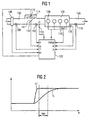
- Fig. 1 shows the technical environment of an internal combustion engine 100, in which the present invention can be used.
- the illustrated components become the controller the internal combustion engine 100 explained in more detail.
- the internal combustion engine 100 is an air / fuel mixture fed, and the exhaust gases are in one 104 delivered.
- the intake tract 102 are in the flow direction the intake air seen an air flow meter or Air mass meter 106, for example a hot wire air mass meter, a temperature sensor 108 for detecting the Intake air temperature, a throttle valve 110 with a sensor 111 for detecting the opening angle of the throttle valve 110, a pressure sensor 112 and one or more injectors 113 attached.
- the air flow meter or air mass meter 106 and pressure sensor 112 alternatively available.
- a bypass channel 114 in which an idle actuator 115 is arranged.
- Bypass channel 114 and idle actuator 115 may be omitted, when the regulation of the idling speed with the help of Throttle 110 takes place.
- Bypass valves may be present, for example, when connecting an air conditioner a sufficient idle speed to ensure.
- an oxygen sensor 116 attached in the exhaust passage 104 .
- On the internal combustion engine 100 are a crank angle sensor 118 and a sensor 119 for detection the temperature of the internal combustion engine 100 attached.
- the internal combustion engine 100 for Ignition of the air / fuel mixture in the cylinders, for example four spark plugs 120.
- the output signals of the sensors described become a central controller 122 transmitted.
- it acts These are the following signals: A signal m of the air flow meter or air mass meter 106, a signal T of Temperature sensor 108 for detecting the intake air temperature, a signal ⁇ of the sensor 111 for detecting the opening angle the throttle valve 110, a signal p of the pressure sensor 112, a signal ⁇ of the oxygen sensor 116, a Signal w of the crank angle sensor 118 and a signal TBKM the sensor 119 for detecting the temperature of the internal combustion engine 100.
- the controller 122 evaluates the sensor signals and controls the injector or injectors 113, the idle actuator 115 and the ignition timing for the Spark plugs 120 on.
- the calculation of the dynamic range must be completed at the closing time t s of the ignition coil, ie be carried out long before the filling angle.
- the Air change changes are used by the difference the main load signal tL present at the filling angle and the main load signal present at the beginning of the dynamic phase is represented, i. it is necessary that To predict filling difference or load difference.
- the method known from DE 44 01 828 A1 allows an approximate prediction of the filling angle Load signal tL, which in the following as a future Load signal tLPr is called. This is especially exploited that the main factor influencing the course of the future load signal tLPr, the opening angle ⁇ Throttle 111, is known and that the signal ⁇ the signal tL leads the way a lot. Further details are in Fig. 2 shown.
- Fig. 2 shows a diagram in which the main load signal tL (dashed line) and the auxiliary load signal tL '(solid line Line) are plotted against the crank angle w.
- the curves for tL and tL 'coincide left to right.
- wPr is the prediction angle, that is the difference from the future crank angle for which the future Load signal tLPr is predicted - usually this is the filling angle - and the instantaneous crank angle w.
- the speed range stkrnx, in the internal combustion engine is currently determined and stored in a register in the form of a RAM memory.
- the stkrnx in previous to this speed range Dynamic phases adapted dynamic bias wkrdya is read from the RAM memory and output. While the dynamic phase possibly occurring knocking events become strong and normal in terms of their strength classified. From this classification will be on End of dynamic phase at time tdyen, e.g.
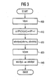
- FIG. 3 shows a flowchart for the basic sequence a first embodiment of the invention.
- stkrnx and stkrdrlx now address the adaptation range, from the lead wkrdya for the subsequent Dynamic phase is read (step 420).
- This value may optionally be with a temperature dependent one Factor weighted and then for further processing output.
- Fig. 4 shows a schematic representation of the temporal History of the air filling and the air filling gradient Explanation of a second embodiment of the invention, and in case c when the predicted at tdyst Load change and in case of non-occurrence d tdyst predicted load change.
- FIG the second embodiment a plausibility of the correction value in the sense that actually during the Dynamics occurred air charge change ⁇ rl with the predicted Air charge change ⁇ rlPr in plausible (Applicable) borders.
- the adaptation range only above the expected air filling difference ⁇ rlPr in shape prevailschpannen a load difference range stkrdrlx (ie not above the speed range).
- a load difference range stkrdrlx ie not above the speed range.
- the above-mentioned temperature-dependent Weighting factor is therefore expediently instead of just over the modeled temperature evtmod at the intake valve in addition above the speed n in the form of a characteristic diagram (n, evtmod). This should be the actual speed dependencies in the physically correct places be detected.
- the further procedure corresponds to that the first or second embodiment.
- the invention is not limited to the above example Prediction procedure limited.
- Prediction procedure may be the update error of the ignition angle calculation by using a predicated signal below additional consideration of camshaft adjustment and exhaust gas recirculation can be compensated.
Landscapes
- Engineering & Computer Science (AREA)
- Chemical & Material Sciences (AREA)
- Combustion & Propulsion (AREA)
- Mechanical Engineering (AREA)
- General Engineering & Computer Science (AREA)
- Signal Processing (AREA)
- Combined Controls Of Internal Combustion Engines (AREA)
- Electrical Control Of Ignition Timing (AREA)
- Electrical Control Of Air Or Fuel Supplied To Internal-Combustion Engine (AREA)
- Exhaust-Gas Circulating Devices (AREA)
Claims (10)
- Dispositif permettant de supprimer le cognement dans un moteur à combustion interne dans des états de fonctionnement dynamiques, comprenant :caractérisé en ce queun dispositif d'enregistrement qui enregistre au moins un paramètre de fonctionnement du moteur à combustion interne,une unité de commande qui calcule un angle d'allumage en fonction d'au moins un paramètre de fonctionnement du moteur à combustion interne en prenant en compte, dans l'état de fonctionnement dynamique, une dérivée dynamique (wkrdya),un dispositif de surveillance du cognement qui enregistre la force des événements de cognement,un dispositif de détection des phases dynamiques qui détecte un état de fonctionnement dynamique du moteur à combustion interne, où l'unité de commande calcule, à partir d'au moins un paramètre de fonctionnement, un signal de charge actuel (tL,rl), un signal de charge futur (tLPr,rlPr), ainsi que la différence de charge entre le signal de charge actuel et le signal de charge futur (ΔrlPr = rl - rlPr), et lit alors la dérivée dynamique (wkrdya) à partir d'une caractéristique stockée dans l'appareil de commande, la dérivée dynamique respective (wkrdya) étant lue à partir d'une zone de la caractéristique dont la plage de différence de charge (stkrdrlx) correspond à une différence de charge actuelle (Δ rlPr),
la valeur respective de la dérivée dynamique dans la caractéristique, à la fin d'un état de fonctionnement dynamique, est adaptée en fonction de la force des événements de cognement enregistrés au moyen du dispositif de surveillance du cognement. - Dispositif selon la revendication 1,
caractérisé en ce que
le dispositif d'enregistrement détermine en tant que paramètre de fonctionnement le régime (n) et/ou la température de l'air d'admission et/ou l'angle d'ouverture du papillon des gaz et/ou la pression régnant dans la tubulure d'admission et/ou le débit ou la masse d'air admis et/ou l'angle de vilebrequin et/ou la température du moteur à combustion interne. - Dispositif selon la revendication 2,
caractérisé en ce que
les valeurs de dérivée dynamique contenues dans la caractéristique sont en outre associées à des plages de régime (stkrnx), la dérivée dynamique respective (wkrdya) étant lue à partir d'une zone de la caractéristique dont la plage de régime (stkrnx) correspond au régime actuel (n). - Dispositif selon l'une des revendications précédentes,
caractérisé en ce que
le dispositif de détection des phases dynamiques détecte l'état de fonctionnement dynamique du moteur à combustion interne lorsque le gradient de charge dépasse une valeur de seuil prédéterminée. - Dispositif selon l'une des revendications précédentes,
caractérisé en ce que
l'unité de commande calcule le signal de charge futur à partir d'un signal de charge principal actuel (tL), d'un signal de charge auxiliaire actuel (tL') précédant le signal de charge principal actuel, et d'un intervalle d'angle de vilebrequin (wPr), prédéterminé en fonction du temps de calcul exprimé en unités de temps ou en unités d'angle de vilebrequin. - Dispositif selon la revendication 5,
caractérisé en ce que
le signal de charge auxiliaire actuel (tL') est déterminé à partir de l'angle d'ouverture (α) du papillon des gaz (110), du régime (n) du moteur à combustion interne et d'un débit d'air (qLL) s'écoulant le cas échéant à travers un canal de dérivation (114) jusqu'au papillon des gaz (110) et/ou à travers des soupapes de dérivation supplémentaires. - Dispositif selon la revendication 5 ou 6,
caractérisé en ce que
le signal de charge principal actuel (tL) est déterminé à partir de la pression mesurée dans la tubulure d'admission (p) et du régime (n), à partir de la masse d'air (m) enregistrée par un débitmètre d'air massique (106), ou par la filtration du signal de charge auxiliaire actuel (tL'). - Dispositif selon l'une des revendications précédentes,
caractérisé en ce que
la détermination du signal de charge futur (tLPr,rlPr) s'effectue en prenant en compte le déplacement de l'arbre à cames et/ou le réacheminement des gaz d'échappement. - Dispositif selon l'une des revendications précédentes,
caractérisé en ce que
l'unité de commande détermine la différence de charge (ΔlPr) au moment de l'enregistrement de l'état de fonctionnement dynamique. - Dispositif selon l'une des revendications précédentes,
caractérisé en ce que
l'unité de commande compare la différence de charge enregistrée au début de l'état de fonctionnement dynamique avec une différence de charge enregistrée à la fin de l'état de fonctionnement dynamique et adapte la valeur de dérivée dynamique dans la caractéristique, stockée dans la zone de la caractéristique respective, à la fin d'un état de fonctionnement dynamique, uniquement lorsque la différence entre les différences de charge au début et à la fin de l'état de fonctionnement dynamique est inférieure à une valeur prédéterminée.
Applications Claiming Priority (3)
| Application Number | Priority Date | Filing Date | Title |
|---|---|---|---|
| DE19902209 | 1999-01-21 | ||
| DE19902209A DE19902209A1 (de) | 1999-01-21 | 1999-01-21 | Vorrichtung zum Unterdrücken von Motorklopfen einer Brennkraftmaschine |
| PCT/DE1999/003330 WO2000043670A1 (fr) | 1999-01-21 | 1999-10-16 | Dispositif pour supprimer le cognement dans un moteur a combustion interne |
Publications (2)
| Publication Number | Publication Date |
|---|---|
| EP1147309A1 EP1147309A1 (fr) | 2001-10-24 |
| EP1147309B1 true EP1147309B1 (fr) | 2005-12-28 |
Family
ID=7894898
Family Applications (1)
| Application Number | Title | Priority Date | Filing Date |
|---|---|---|---|
| EP99960785A Expired - Lifetime EP1147309B1 (fr) | 1999-01-21 | 1999-10-16 | Dispositif pour supprimer le cognement dans un moteur a combustion interne |
Country Status (9)
| Country | Link |
|---|---|
| US (1) | US6513495B1 (fr) |
| EP (1) | EP1147309B1 (fr) |
| JP (1) | JP2002535551A (fr) |
| KR (1) | KR100679475B1 (fr) |
| CN (1) | CN1318750C (fr) |
| BR (1) | BR9916939A (fr) |
| DE (2) | DE19902209A1 (fr) |
| RU (1) | RU2230931C2 (fr) |
| WO (1) | WO2000043670A1 (fr) |
Cited By (1)
| Publication number | Priority date | Publication date | Assignee | Title |
|---|---|---|---|---|
| DE102008018620A1 (de) * | 2008-04-11 | 2009-10-15 | Bayerische Motoren Werke Aktiengesellschaft | Vorrichtung zur Bestimmung des Zündwinkels in einem Steuergerät für elektronische Steuerungen von Brennkraftmaschinen |
Families Citing this family (34)
| Publication number | Priority date | Publication date | Assignee | Title |
|---|---|---|---|---|
| DE10037569B4 (de) * | 2000-08-02 | 2014-02-13 | Robert Bosch Gmbh | Verfahren, Computerprogramm sowie Steuereinrichtung zur Ermittlung der Luftmasse, die einer Brennkraftmaschine über ein Ansaugrohr zugeführt wird |
| US20030079503A1 (en) * | 2001-10-26 | 2003-05-01 | Cook Glen B. | Direct bonding of glass articles for drawing |
| JP4065182B2 (ja) * | 2001-11-20 | 2008-03-19 | ロベルト・ボッシュ・ゲゼルシャフト・ミト・ベシュレンクテル・ハフツング | 内燃機関の運転方法および内燃機関の運転制御装置 |
| DE10257994A1 (de) * | 2002-12-12 | 2004-07-01 | Robert Bosch Gmbh | Verfahren zur Zündwinkelbestimmung |
| JP2005307844A (ja) * | 2004-04-21 | 2005-11-04 | Kokusan Denki Co Ltd | 2サイクル内燃機関用点火制御方法及び点火制御装置 |
| US7467614B2 (en) * | 2004-12-29 | 2008-12-23 | Honeywell International Inc. | Pedal position and/or pedal change rate for use in control of an engine |
| US7389773B2 (en) | 2005-08-18 | 2008-06-24 | Honeywell International Inc. | Emissions sensors for fuel control in engines |
| US7614384B2 (en) * | 2007-11-02 | 2009-11-10 | Gm Global Technology Operations, Inc. | Engine torque control with desired state estimation |
| US8050841B2 (en) * | 2008-05-21 | 2011-11-01 | GM Global Technology Operations LLC | Security for engine torque input air-per-cylinder calculations |
| US20090326754A1 (en) * | 2008-06-30 | 2009-12-31 | Honeywell International Inc. | Systems and methods for engine diagnosis using wavelet transformations |
| US8060290B2 (en) | 2008-07-17 | 2011-11-15 | Honeywell International Inc. | Configurable automotive controller |
| DE102008042475B4 (de) * | 2008-09-30 | 2019-10-24 | Robert Bosch Gmbh | Verfahren und Vorrichtung zum Feststellen eines Klopfereignisses während eines Umschaltvorgangs zwischen Betriebsarten eines Verbrennungsmotors |
| US8620461B2 (en) | 2009-09-24 | 2013-12-31 | Honeywell International, Inc. | Method and system for updating tuning parameters of a controller |
| US8504175B2 (en) | 2010-06-02 | 2013-08-06 | Honeywell International Inc. | Using model predictive control to optimize variable trajectories and system control |
| US9677493B2 (en) | 2011-09-19 | 2017-06-13 | Honeywell Spol, S.R.O. | Coordinated engine and emissions control system |
| JP5754512B2 (ja) * | 2011-10-24 | 2015-07-29 | 日産自動車株式会社 | 火花点火式内燃機関及び火花点火式内燃機関の制御方法 |
| US20130111905A1 (en) | 2011-11-04 | 2013-05-09 | Honeywell Spol. S.R.O. | Integrated optimization and control of an engine and aftertreatment system |
| US9650934B2 (en) | 2011-11-04 | 2017-05-16 | Honeywell spol.s.r.o. | Engine and aftertreatment optimization system |
| US10947946B2 (en) * | 2013-05-22 | 2021-03-16 | Ford Global Technologies, Llc | Enhanced VDE knock control |
| JP6154302B2 (ja) * | 2013-11-28 | 2017-06-28 | 日本特殊陶業株式会社 | 点火時期制御装置及び点火時期制御システム |
| FR3014956B1 (fr) * | 2013-12-12 | 2015-12-25 | Renault Sas | Dispositif et procede de controle du fonctionnement d'une vanne de recirculation des gaz d'echappement au moyen du dispositif de gestion de l'avance a l'allumage |
| EP3051367B1 (fr) | 2015-01-28 | 2020-11-25 | Honeywell spol s.r.o. | Approche et système de manipulation de contraintes pour des perturbations mesurées avec une prévisualisation incertaine |
| US9628011B2 (en) * | 2015-02-05 | 2017-04-18 | Ford Global Technologies, Llc | Engine speed control via alternator load shedding |
| EP3056706A1 (fr) | 2015-02-16 | 2016-08-17 | Honeywell International Inc. | Approche de modélisation de système de post-traitement et d'identification de modèle |
| EP3091212A1 (fr) | 2015-05-06 | 2016-11-09 | Honeywell International Inc. | Approche d'identification pour modèles de valeurs moyennes de moteurs à combustion interne |
| US9938953B2 (en) * | 2015-06-17 | 2018-04-10 | Ford Global Technologies, Llc | Method and system for engine control |
| EP3734375B1 (fr) | 2015-07-31 | 2023-04-05 | Garrett Transportation I Inc. | Résolveur de programme quadratique pour mpc utilisant une commande variable |
| US10272779B2 (en) | 2015-08-05 | 2019-04-30 | Garrett Transportation I Inc. | System and approach for dynamic vehicle speed optimization |
| US10415492B2 (en) | 2016-01-29 | 2019-09-17 | Garrett Transportation I Inc. | Engine system with inferential sensor |
| US10036338B2 (en) | 2016-04-26 | 2018-07-31 | Honeywell International Inc. | Condition-based powertrain control system |
| US10124750B2 (en) | 2016-04-26 | 2018-11-13 | Honeywell International Inc. | Vehicle security module system |
| EP3548729B1 (fr) | 2016-11-29 | 2023-02-22 | Garrett Transportation I Inc. | Capteur de flux inférentiel |
| US11057213B2 (en) | 2017-10-13 | 2021-07-06 | Garrett Transportation I, Inc. | Authentication system for electronic control unit on a bus |
| CN112283003B (zh) * | 2020-10-22 | 2022-07-12 | 中国第一汽车股份有限公司 | 一种点火角修正方法、装置、设备及存储介质 |
Family Cites Families (7)
| Publication number | Priority date | Publication date | Assignee | Title |
|---|---|---|---|---|
| FR2546975B1 (fr) | 1983-06-03 | 1989-03-31 | Mitsubishi Electric Corp | Dispositif pour supprimer le cognement dans les moteurs a combustion interne |
| JPS6296778A (ja) * | 1985-10-22 | 1987-05-06 | Nissan Motor Co Ltd | 点火時期制御装置 |
| JP2732923B2 (ja) * | 1988-12-24 | 1998-03-30 | ローベルト ボッシュ ゲゼルシャフト ミット ベシュレンクテル ハフツング | 適応型加速時ノック制御方法 |
| DE4336775A1 (de) * | 1993-10-28 | 1995-05-04 | Bosch Gmbh Robert | Verfahren und Vorrrichtung zum Steuern der Abgastemperatur bei einem Verbrennungsmotor mit Klopfregelung |
| DE4401828B4 (de) * | 1994-01-22 | 2004-02-19 | Robert Bosch Gmbh | Verfahren und Vorrichtung zur Vorhersage eines zukünftigen Lastsignals im Zusammenhang mit der Steuerung einer Brennkraftmaschine |
| US5503126A (en) * | 1994-05-20 | 1996-04-02 | Nippondenso Co., Ltd. | Ignition timing control system for internal combustion engines |
| US5445127A (en) * | 1994-08-31 | 1995-08-29 | Ford Motor Company | Method and system for reducing engine spark knock during a rapid transient |
-
1999
- 1999-01-21 DE DE19902209A patent/DE19902209A1/de not_active Withdrawn
- 1999-10-16 WO PCT/DE1999/003330 patent/WO2000043670A1/fr active IP Right Grant
- 1999-10-16 EP EP99960785A patent/EP1147309B1/fr not_active Expired - Lifetime
- 1999-10-16 RU RU2001122101/06A patent/RU2230931C2/ru not_active IP Right Cessation
- 1999-10-16 DE DE59912997T patent/DE59912997D1/de not_active Expired - Lifetime
- 1999-10-16 JP JP2000595055A patent/JP2002535551A/ja active Pending
- 1999-10-16 CN CNB998148865A patent/CN1318750C/zh not_active Expired - Fee Related
- 1999-10-16 BR BR9916939-8A patent/BR9916939A/pt not_active IP Right Cessation
- 1999-10-16 KR KR1020017009137A patent/KR100679475B1/ko not_active IP Right Cessation
-
2001
- 2001-10-30 US US09/889,839 patent/US6513495B1/en not_active Expired - Fee Related
Cited By (2)
| Publication number | Priority date | Publication date | Assignee | Title |
|---|---|---|---|---|
| DE102008018620A1 (de) * | 2008-04-11 | 2009-10-15 | Bayerische Motoren Werke Aktiengesellschaft | Vorrichtung zur Bestimmung des Zündwinkels in einem Steuergerät für elektronische Steuerungen von Brennkraftmaschinen |
| DE102008018620B4 (de) * | 2008-04-11 | 2017-10-12 | Bayerische Motoren Werke Aktiengesellschaft | Vorrichtung zur Bestimmung des Zündwinkels in einem Steuergerät für elektronische Steuerungen von Brennkraftmaschinen |
Also Published As
| Publication number | Publication date |
|---|---|
| CN1331782A (zh) | 2002-01-16 |
| WO2000043670A1 (fr) | 2000-07-27 |
| KR20020005576A (ko) | 2002-01-17 |
| JP2002535551A (ja) | 2002-10-22 |
| DE19902209A1 (de) | 2000-07-27 |
| RU2230931C2 (ru) | 2004-06-20 |
| US6513495B1 (en) | 2003-02-04 |
| BR9916939A (pt) | 2001-11-06 |
| CN1318750C (zh) | 2007-05-30 |
| DE59912997D1 (de) | 2006-02-02 |
| EP1147309A1 (fr) | 2001-10-24 |
| KR100679475B1 (ko) | 2007-02-07 |
Similar Documents
| Publication | Publication Date | Title |
|---|---|---|
| EP1147309B1 (fr) | Dispositif pour supprimer le cognement dans un moteur a combustion interne | |
| EP0051723B1 (fr) | Procédé de mise en oeuvre d'un système électronique de commande d'un moteur à combustion interne | |
| EP0166033B1 (fr) | Dispositif de régulation du cliquetis d'un moteur à combustion interne | |
| DE3303350C2 (de) | Steuervorrichtung für den Ladedruck einer Brennkraftmaschine mit Turbolader | |
| EP0938629B1 (fr) | Procede pour determiner l'angle d'allumage dans des systemes d'allumage de moteurs a combustion interne | |
| DE4324312C2 (de) | Verfahren zum Betreiben einer Brennkraftmaschine in einem Magergemisch-Verbrennungsbereich | |
| DE112008001304B4 (de) | Zündzeitpunkt-Steuerungsvorrichtung für einen Verbrennungsmotor | |
| DE3311968C2 (fr) | ||
| DE3201756C2 (de) | Verfahren zum Steuern einer Brennkraftmaschine mit Vorverdichter | |
| EP0042163A2 (fr) | Procédé de commande de l'alimentation du combustible et du point d'allumage dans un moteur à combustion | |
| EP0902863B1 (fr) | Procede de reglage du cliquetis dans les moteurs a combustion interne a cylindres multiples | |
| DE4401828B4 (de) | Verfahren und Vorrichtung zur Vorhersage eines zukünftigen Lastsignals im Zusammenhang mit der Steuerung einer Brennkraftmaschine | |
| DE3735382C3 (de) | Vorrichtung zum Steuern des Zündzeitpunkts und des Ladedrucks bei einer Mehrzylinder-Brennkraftmaschine mit Turbolader | |
| DE3221641C2 (fr) | ||
| DE69220449T2 (de) | Steuerungseinrichtung für einen Verbrennungsmotor mit einer Abgasrückführvorrichtung | |
| DE102010000289A1 (de) | Abgas-Emissions-Steuerungssystem | |
| EP0678163B1 (fr) | Procede de reglage adaptatif du cliquetis d'un moteur a combustion interne | |
| DE3106579C2 (fr) | ||
| DE4041505C2 (de) | Verfahren und Vorrichtung zur Erfassung einer veränderlichen Größe für eine Brennkraftmaschine an einem Kraftfahrzeug | |
| DE19501458B4 (de) | Verfahren zur Adaption der Warmlaufanreicherung | |
| EP1085187B1 (fr) | Méthode et dispositif pour augmenter le couple d'un moteur à combustion interne à injection directe avec le turbocompresseur d'échappement | |
| DE19651238C2 (de) | Einrichtung Bestimmung des Zündwinkels einer Brennkraftmaschine | |
| DE3930487C2 (de) | Verfahren zur Steuerung des Zündzeitpunktes und Zündzeitpunktsteuereinrichtung für eine Brennkraftmaschine eines Kraftfahrzeuges | |
| DE3629197C2 (fr) | ||
| DE4022704C2 (de) | System zur Steuerung des Zündzeitpunkts einer Brennkraftmaschine |
Legal Events
| Date | Code | Title | Description |
|---|---|---|---|
| PUAI | Public reference made under article 153(3) epc to a published international application that has entered the european phase |
Free format text: ORIGINAL CODE: 0009012 |
|
| 17P | Request for examination filed |
Effective date: 20010821 |
|
| AK | Designated contracting states |
Kind code of ref document: A1 Designated state(s): AT BE CH CY DE DK ES FI FR GB GR IE IT LI LU MC NL PT SE |
|
| RBV | Designated contracting states (corrected) |
Designated state(s): DE ES FR GB IT |
|
| 17Q | First examination report despatched |
Effective date: 20041005 |
|
| GRAP | Despatch of communication of intention to grant a patent |
Free format text: ORIGINAL CODE: EPIDOSNIGR1 |
|
| GRAS | Grant fee paid |
Free format text: ORIGINAL CODE: EPIDOSNIGR3 |
|
| GRAA | (expected) grant |
Free format text: ORIGINAL CODE: 0009210 |
|
| AK | Designated contracting states |
Kind code of ref document: B1 Designated state(s): DE ES FR GB IT |
|
| PG25 | Lapsed in a contracting state [announced via postgrant information from national office to epo] |
Ref country code: IT Free format text: LAPSE BECAUSE OF FAILURE TO SUBMIT A TRANSLATION OF THE DESCRIPTION OR TO PAY THE FEE WITHIN THE PRESCRIBED TIME-LIMIT;WARNING: LAPSES OF ITALIAN PATENTS WITH EFFECTIVE DATE BEFORE 2007 MAY HAVE OCCURRED AT ANY TIME BEFORE 2007. THE CORRECT EFFECTIVE DATE MAY BE DIFFERENT FROM THE ONE RECORDED. Effective date: 20051228 Ref country code: GB Free format text: LAPSE BECAUSE OF FAILURE TO SUBMIT A TRANSLATION OF THE DESCRIPTION OR TO PAY THE FEE WITHIN THE PRESCRIBED TIME-LIMIT Effective date: 20051228 |
|
| REG | Reference to a national code |
Ref country code: GB Ref legal event code: FG4D Free format text: NOT ENGLISH |
|
| REF | Corresponds to: |
Ref document number: 59912997 Country of ref document: DE Date of ref document: 20060202 Kind code of ref document: P |
|
| PG25 | Lapsed in a contracting state [announced via postgrant information from national office to epo] |
Ref country code: ES Free format text: LAPSE BECAUSE OF FAILURE TO SUBMIT A TRANSLATION OF THE DESCRIPTION OR TO PAY THE FEE WITHIN THE PRESCRIBED TIME-LIMIT Effective date: 20060408 |
|
| GBV | Gb: ep patent (uk) treated as always having been void in accordance with gb section 77(7)/1977 [no translation filed] |
Effective date: 20051228 |
|
| ET | Fr: translation filed | ||
| PLBE | No opposition filed within time limit |
Free format text: ORIGINAL CODE: 0009261 |
|
| STAA | Information on the status of an ep patent application or granted ep patent |
Free format text: STATUS: NO OPPOSITION FILED WITHIN TIME LIMIT |
|
| 26N | No opposition filed |
Effective date: 20060929 |
|
| PGFP | Annual fee paid to national office [announced via postgrant information from national office to epo] |
Ref country code: IT Payment date: 20091024 Year of fee payment: 11 Ref country code: FR Payment date: 20091110 Year of fee payment: 11 |
|
| PG25 | Lapsed in a contracting state [announced via postgrant information from national office to epo] |
Ref country code: FR Free format text: LAPSE BECAUSE OF NON-PAYMENT OF DUE FEES Effective date: 20101102 |
|
| REG | Reference to a national code |
Ref country code: FR Ref legal event code: ST Effective date: 20110630 |
|
| PG25 | Lapsed in a contracting state [announced via postgrant information from national office to epo] |
Ref country code: IT Free format text: LAPSE BECAUSE OF NON-PAYMENT OF DUE FEES Effective date: 20101016 |
|
| PGFP | Annual fee paid to national office [announced via postgrant information from national office to epo] |
Ref country code: DE Payment date: 20131217 Year of fee payment: 15 |
|
| REG | Reference to a national code |
Ref country code: DE Ref legal event code: R119 Ref document number: 59912997 Country of ref document: DE |
|
| PG25 | Lapsed in a contracting state [announced via postgrant information from national office to epo] |
Ref country code: DE Free format text: LAPSE BECAUSE OF NON-PAYMENT OF DUE FEES Effective date: 20150501 |