EP1147309B1 - Device for suppressing engine knocking in an internal combustion engine - Google Patents
Device for suppressing engine knocking in an internal combustion engine Download PDFInfo
- Publication number
- EP1147309B1 EP1147309B1 EP99960785A EP99960785A EP1147309B1 EP 1147309 B1 EP1147309 B1 EP 1147309B1 EP 99960785 A EP99960785 A EP 99960785A EP 99960785 A EP99960785 A EP 99960785A EP 1147309 B1 EP1147309 B1 EP 1147309B1
- Authority
- EP
- European Patent Office
- Prior art keywords
- dynamic
- load signal
- load
- internal combustion
- instantaneous
- Prior art date
- Legal status (The legal status is an assumption and is not a legal conclusion. Google has not performed a legal analysis and makes no representation as to the accuracy of the status listed.)
- Expired - Lifetime
Links
Images


Classifications
-
- F—MECHANICAL ENGINEERING; LIGHTING; HEATING; WEAPONS; BLASTING
- F02—COMBUSTION ENGINES; HOT-GAS OR COMBUSTION-PRODUCT ENGINE PLANTS
- F02D—CONTROLLING COMBUSTION ENGINES
- F02D43/00—Conjoint electrical control of two or more functions, e.g. ignition, fuel-air mixture, recirculation, supercharging or exhaust-gas treatment
- F02D43/04—Conjoint electrical control of two or more functions, e.g. ignition, fuel-air mixture, recirculation, supercharging or exhaust-gas treatment using only digital means
-
- F—MECHANICAL ENGINEERING; LIGHTING; HEATING; WEAPONS; BLASTING
- F02—COMBUSTION ENGINES; HOT-GAS OR COMBUSTION-PRODUCT ENGINE PLANTS
- F02P—IGNITION, OTHER THAN COMPRESSION IGNITION, FOR INTERNAL-COMBUSTION ENGINES; TESTING OF IGNITION TIMING IN COMPRESSION-IGNITION ENGINES
- F02P5/00—Advancing or retarding ignition; Control therefor
- F02P5/04—Advancing or retarding ignition; Control therefor automatically, as a function of the working conditions of the engine or vehicle or of the atmospheric conditions
- F02P5/145—Advancing or retarding ignition; Control therefor automatically, as a function of the working conditions of the engine or vehicle or of the atmospheric conditions using electrical means
- F02P5/15—Digital data processing
- F02P5/152—Digital data processing dependent on pinking
-
- F—MECHANICAL ENGINEERING; LIGHTING; HEATING; WEAPONS; BLASTING
- F02—COMBUSTION ENGINES; HOT-GAS OR COMBUSTION-PRODUCT ENGINE PLANTS
- F02D—CONTROLLING COMBUSTION ENGINES
- F02D37/00—Non-electrical conjoint control of two or more functions of engines, not otherwise provided for
- F02D37/02—Non-electrical conjoint control of two or more functions of engines, not otherwise provided for one of the functions being ignition
-
- Y—GENERAL TAGGING OF NEW TECHNOLOGICAL DEVELOPMENTS; GENERAL TAGGING OF CROSS-SECTIONAL TECHNOLOGIES SPANNING OVER SEVERAL SECTIONS OF THE IPC; TECHNICAL SUBJECTS COVERED BY FORMER USPC CROSS-REFERENCE ART COLLECTIONS [XRACs] AND DIGESTS
- Y02—TECHNOLOGIES OR APPLICATIONS FOR MITIGATION OR ADAPTATION AGAINST CLIMATE CHANGE
- Y02T—CLIMATE CHANGE MITIGATION TECHNOLOGIES RELATED TO TRANSPORTATION
- Y02T10/00—Road transport of goods or passengers
- Y02T10/10—Internal combustion engine [ICE] based vehicles
- Y02T10/40—Engine management systems
Definitions
- the present invention relates to a device for suppressing of engine knock of an internal combustion engine.
- From DE 34 204 65 C2 is a device for suppressing engine knock of an internal combustion engine known.
- This known device are operating parameters of Internal combustion engine detected, and due to these detected operating parameters are the respective in a control unit Manipulated variables for the processes to be controlled, in particular Ignition and injection, determined. For example based on speed and applied load of optimal ignition timing calculated.
- the known device is also a knock detector provided, the cylinder combustion cylinder noise detected.
- the signals to the knock detector become a Knöpfsignalauswertesciens forwarded and there after filtering out the background noise with a Reference level compared.
- Became a knocking burn detected it is determined by the speed and load Ignition timing in this cylinder for knock suppression in the direction of late and thus away from the knock limit adjusted. After a possible number of knock-free burns this changed ignition timing is restored gradually to the control unit specific manipulated variable introduced. Because the risk of knocking burns when cold engine does not exist, it is common for the knock control only after reaching a predefinable engine temperature, So after warming up the engine, active to switch. Below this release temperature can with Security no knocking occur as the thermal conditions in the combustion chamber do not allow this.
- a future Load signal determines the expected relative air charge represents.
- the future load signal turns off a current main load signal, a current auxiliary load signal, that leads the current main load signal, and a crank angle interval determined.
- the crank angle interval depends on the time units or crank angle units expressed fuel pre-storage, the duration of the fuel injection and the calculation time predetermined. The inclusion of the crank angle interval has the advantage that the determination of the future load signal be carried out at the latest possible time can and thereby high accuracy is achieved.
- the future load signal with a Lowpass filter is determined whose filter constant load-dependent is possible.
- the filter constant is added rising load from a first characteristic and read with falling load from a second characteristic curve.
- the auxiliary load signal is calculated from the opening angle of the throttle valve, the speed of the internal combustion engine and a optionally through a bypass channel to the throttle flowing air quantity determined and depending on the temperature the intake air and the barometric height corrected.
- the Auxiliary load signal also from the detected with an air mass meter Air mass can be determined, which is usually one higher accuracy in this operating range.
- the main load signal can z. B. from the measured intake manifold pressure and the speed, from that with an air mass meter detected air mass or by filtering the auxiliary load signal be determined.
- the method can be used both in non-stationary operation as also be used in stationary operation, as in the Determining the future load signal on the main load signal adapted auxiliary load signal is used.
- the adjustment value needed for the adjustment of the auxiliary load signal is by integrating the deviation between the main load signal and the balance provided with filtered auxiliary load signal determined.
- the filtered one Auxiliary load signal is thereby filtered by the corrected Auxiliary load signal generated.
- the problem underlying the present invention is that gasoline engines in dynamic changes the load increased compared to the stationary operation Knock tendency, which is usually by issuing a so-called adaptive dynamic bias, i. an additional one Ignition retard adjustment during the dynamic phase trying to counter.
- This additional dynamic advance is output when the load gradient, i. the Instantaneous speed or slope of the load change a exceeds the applicable threshold.
- the dynamics reserve is then maintained for an applicable time and then zeroed out.
- t denotes the time tdyst the start time of the dynamic phase
- tdyena the end time the dynamic phase for the case a
- tdyenb the end time the dynamic phase for the case b
- rl the air filling
- drl the air filling gradient.
- case a lies a large ring air change ⁇ rla before
- Case b is a small change in airflow as fast ⁇ rlb.
- the device according to the invention with the features of the claim 1 has over the known approaches to the Advantage that it is a physically based, dynamic more precise determination of the dynamics and thus a better suppression of tapping in the dynamic phase allows.
- the proposed adaptation algorithm leads to more accurate Adaptation values and thus an improved dynamic behavior.
- the plausibility of the adaptation values can be improved assess and simplify the application process.
- load signal and (air) filling signal used here synonymous, since they have a simple proportionality factor linked together are.
- the correction device designed such that the dynamics of at least a detected operating parameter, preferably the Speed, is dependent.
- the correction device designed to predict the predicted Load difference by detecting the load signal to a prior to the ignition timing to be determined; Predicting a future load signal to a later, prior to the ignition timing to be determined; and forming the difference of the future load signal and the load signal determined.
- the correction device designed to reflect the future Load signal from a current main load signal, a current one Auxiliary load signal corresponding to the current main load signal leads, and a crank angle interval that depends from that expressed in units of time or crankshaft units Calculation time is predicable, predicts.
- the current Main load signal from the measured intake manifold pressure and the speed from which detected with an air mass meter Air mass or by filtering the current auxiliary load signal determined.
- the correction device designed such that the predictions of the future load signal taking into account the camshaft adjustment and / or the exhaust gas recirculation takes place.
- the dynamic phase detection device designed so that they detects a dynamic phase of the internal combustion engine from that the load gradient exceeds a predetermined threshold.
- the correction device designed so that they the load difference at the time of recording a dynamic phase.
- the correction device designed so that they at the beginning the dynamic phase predicted load difference with an am End of the dynamic phase recorded load difference compares and the adaptation only allows if the difference is smaller as a predetermined value.
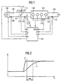
- Fig. 1 shows the technical environment of an internal combustion engine 100, in which the present invention can be used.
- the illustrated components become the controller the internal combustion engine 100 explained in more detail.
- the internal combustion engine 100 is an air / fuel mixture fed, and the exhaust gases are in one 104 delivered.
- the intake tract 102 are in the flow direction the intake air seen an air flow meter or Air mass meter 106, for example a hot wire air mass meter, a temperature sensor 108 for detecting the Intake air temperature, a throttle valve 110 with a sensor 111 for detecting the opening angle of the throttle valve 110, a pressure sensor 112 and one or more injectors 113 attached.
- the air flow meter or air mass meter 106 and pressure sensor 112 alternatively available.
- a bypass channel 114 in which an idle actuator 115 is arranged.
- Bypass channel 114 and idle actuator 115 may be omitted, when the regulation of the idling speed with the help of Throttle 110 takes place.
- Bypass valves may be present, for example, when connecting an air conditioner a sufficient idle speed to ensure.
- an oxygen sensor 116 attached in the exhaust passage 104 .
- On the internal combustion engine 100 are a crank angle sensor 118 and a sensor 119 for detection the temperature of the internal combustion engine 100 attached.
- the internal combustion engine 100 for Ignition of the air / fuel mixture in the cylinders, for example four spark plugs 120.
- the output signals of the sensors described become a central controller 122 transmitted.
- it acts These are the following signals: A signal m of the air flow meter or air mass meter 106, a signal T of Temperature sensor 108 for detecting the intake air temperature, a signal ⁇ of the sensor 111 for detecting the opening angle the throttle valve 110, a signal p of the pressure sensor 112, a signal ⁇ of the oxygen sensor 116, a Signal w of the crank angle sensor 118 and a signal TBKM the sensor 119 for detecting the temperature of the internal combustion engine 100.
- the controller 122 evaluates the sensor signals and controls the injector or injectors 113, the idle actuator 115 and the ignition timing for the Spark plugs 120 on.
- the calculation of the dynamic range must be completed at the closing time t s of the ignition coil, ie be carried out long before the filling angle.
- the Air change changes are used by the difference the main load signal tL present at the filling angle and the main load signal present at the beginning of the dynamic phase is represented, i. it is necessary that To predict filling difference or load difference.
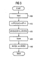
- the method known from DE 44 01 828 A1 allows an approximate prediction of the filling angle Load signal tL, which in the following as a future Load signal tLPr is called. This is especially exploited that the main factor influencing the course of the future load signal tLPr, the opening angle ⁇ Throttle 111, is known and that the signal ⁇ the signal tL leads the way a lot. Further details are in Fig. 2 shown.
- Fig. 2 shows a diagram in which the main load signal tL (dashed line) and the auxiliary load signal tL '(solid line Line) are plotted against the crank angle w.
- the curves for tL and tL 'coincide left to right.
- wPr is the prediction angle, that is the difference from the future crank angle for which the future Load signal tLPr is predicted - usually this is the filling angle - and the instantaneous crank angle w.
- the speed range stkrnx, in the internal combustion engine is currently determined and stored in a register in the form of a RAM memory.
- the stkrnx in previous to this speed range Dynamic phases adapted dynamic bias wkrdya is read from the RAM memory and output. While the dynamic phase possibly occurring knocking events become strong and normal in terms of their strength classified. From this classification will be on End of dynamic phase at time tdyen, e.g.
- FIG. 3 shows a flowchart for the basic sequence a first embodiment of the invention.
- stkrnx and stkrdrlx now address the adaptation range, from the lead wkrdya for the subsequent Dynamic phase is read (step 420).
- This value may optionally be with a temperature dependent one Factor weighted and then for further processing output.
- Fig. 4 shows a schematic representation of the temporal History of the air filling and the air filling gradient Explanation of a second embodiment of the invention, and in case c when the predicted at tdyst Load change and in case of non-occurrence d tdyst predicted load change.
- FIG the second embodiment a plausibility of the correction value in the sense that actually during the Dynamics occurred air charge change ⁇ rl with the predicted Air charge change ⁇ rlPr in plausible (Applicable) borders.
- the adaptation range only above the expected air filling difference ⁇ rlPr in shape prevailschpannen a load difference range stkrdrlx (ie not above the speed range).
- a load difference range stkrdrlx ie not above the speed range.
- the above-mentioned temperature-dependent Weighting factor is therefore expediently instead of just over the modeled temperature evtmod at the intake valve in addition above the speed n in the form of a characteristic diagram (n, evtmod). This should be the actual speed dependencies in the physically correct places be detected.
- the further procedure corresponds to that the first or second embodiment.
- the invention is not limited to the above example Prediction procedure limited.
- Prediction procedure may be the update error of the ignition angle calculation by using a predicated signal below additional consideration of camshaft adjustment and exhaust gas recirculation can be compensated.
Description
Die vorliegende Erfindung betrifft eine Vorrichtung zum Unterdrücken von Motorklopfen einer Brennkraftmaschine.The present invention relates to a device for suppressing of engine knock of an internal combustion engine.
Obwohl auf beliebige Brennkraftmaschinen anwendbar, werden die vorliegende Erfindung sowie die ihr zugrundeliegende Problematik in bezug auf eine Brennkraftmaschine eines Kraftfahrzeuges erläutert.Although applicable to any internal combustion engine the present invention as well as its underlying Problem with respect to an internal combustion engine Motor vehicle explained.
Aus der DE 34 204 65 C2 ist eine Vorrichtung zum Unterdrükken von Motorklopfen einer Brennkraftmaschine bekannt. Bei dieser bekannten Vorrichtung werden Betriebsparameter der Brennkraftmaschine erfaßt, und aufgrund dieser erfaßten Betriebsparameter werden in einer Steuereinheit die jeweiligen Stellgrößen für die zu steuernden Vorgänge, wie insbesondere Zündung und Einspritzung, ermittelt. So wird beispielsweise anhand von Drehzahl und anliegender Last der optimale Zündzeitpunkt berechnet.From DE 34 204 65 C2 is a device for suppressing engine knock of an internal combustion engine known. at This known device are operating parameters of Internal combustion engine detected, and due to these detected operating parameters are the respective in a control unit Manipulated variables for the processes to be controlled, in particular Ignition and injection, determined. For example based on speed and applied load of optimal ignition timing calculated.
Bei der bekannten Vorrichtung ist außerdem ein Klopfdetektor vorgesehen, der die Verbrennungsgeräusche zylinderindividuell erfaßt. Die Signale den Klopfdetektors werden an eine Klopfsignalauswerteschaltung weitergeleitet und dort nach dem Herausfiltern der Hintergrundgeräusche mit einem Referenzpegel verglichen. Wurde eine klopfende Verbrennung erkannt, so wird der anhand von Drehzahl und Last bestimmte Zündzeitpunkt in diesem Zylinder für eine Klopfunterdrükkung in Richtung spät und damit von der Klopfgrenze weg verstellt. Nach einer vorgehbaren Anzahl klopffreier Verbrennungen wird dieser veränderte Zündzeitpunkt wieder schrittweise an die vom Steuergerät bestimmte Stellgröße herangeführt. Da die Gefahr von klopfenden Verbrennungen bei kaltem Motor nicht besteht, ist es üblich, die Klopfregelung erst ab dem Erreichen einer vorgebbaren Motortemperatur, also nach dem Warmlauf der Brennkraftmaschine, aktiv zu schalten. Unterhalb dieser Freigabetemperatur kann mit Sicherheit kein Klopfen auftreten, da die thermischen Verhältnisse im Brennraum dies nicht zulassen.In the known device is also a knock detector provided, the cylinder combustion cylinder noise detected. The signals to the knock detector become a Knöpfsignalauswerteschaltung forwarded and there after filtering out the background noise with a Reference level compared. Became a knocking burn detected, it is determined by the speed and load Ignition timing in this cylinder for knock suppression in the direction of late and thus away from the knock limit adjusted. After a possible number of knock-free burns this changed ignition timing is restored gradually to the control unit specific manipulated variable introduced. Because the risk of knocking burns when cold engine does not exist, it is common for the knock control only after reaching a predefinable engine temperature, So after warming up the engine, active to switch. Below this release temperature can with Security no knocking occur as the thermal conditions in the combustion chamber do not allow this.
In der US-A-5 445 127 wird ein Verfahren beschrieben, bei dem ein Dynamikvorhalt abhängig von der Last aus einer Tabelle im ROM des Steuergeräts ausgelesen wird. Eine Anpassung des Kennfelds ist nicht vorgesehen.In US-A-5 445 127 a method is described in which a dynamic derivative depends on the load a table in the ROM of the controller is read. An adaptation of the map is not provided.
In der DE 44 01 828 A1 ist ein Verfahren angegeben worden, das zur Zeit der Berechnung der zuzumessenden Kraftstoffmenge eine möglichst genaue Vorhersage der Luftfüllung des Zylinders ermöglicht, in den die Kraftstoffmenge eingespritzt wird.In DE 44 01 828 A1 a method has been specified, the at the time of calculating the quantity of fuel to be metered a precise prediction of the air filling of the cylinder allows in which injected the amount of fuel becomes.
Gemäß der Lehre der DE 44 01 828 A1 wird ein zukünftiges Lastsignal ermittelt, das die zu erwartende relative Luftfüllung repräsentiert. Das zukünftige Lastsignal wird aus einem aktuellen Hauptlastsignal, einem aktuellen Hilfslastsignal, das dem aktuellen Hauptlastsignal vorauseilt, und einem Kurbelwinkelintervall ermittelt. Das Kurbelwinkelintervall ist abhängig von der in Zeiteinheiten oder Kurbelwinkeleinheiten ausgedrückten Kraftstoff-Vorlagerung, der Dauer der Kraftstoff-Einspritzung und der Berechnungszeit vorgebbar. Die Einbeziehung des Kurbelwinkelintervalls hat den Vorteil, daß die Ermittlung des zukünftigen Lastsignals zum spätest möglichen Zeitpunkt durchgeführt werden kann und dadurch eine hohe Genauigkeit erreicht wird.According to the teaching of DE 44 01 828 A1, a future Load signal determines the expected relative air charge represents. The future load signal turns off a current main load signal, a current auxiliary load signal, that leads the current main load signal, and a crank angle interval determined. The crank angle interval depends on the time units or crank angle units expressed fuel pre-storage, the duration of the fuel injection and the calculation time predetermined. The inclusion of the crank angle interval has the advantage that the determination of the future load signal be carried out at the latest possible time can and thereby high accuracy is achieved.
Zweckmäßig ist es, daß das zukünftige Lastsignal mit einem Tiefpaßfilter ermittelt wird, dessen Filterkonstante lastabhängig Vorgehbar ist. Die Filterkonstante wird bei steigender Last aus einer ersten Kennlinie ausgelesen und bei fallender Last aus einer zweiten Kennlinie. Dadurch wird eine besonders rechenzeitsparende Vorausbestimmung der Luftfüllung möglich.It is expedient that the future load signal with a Lowpass filter is determined whose filter constant load-dependent is possible. The filter constant is added rising load from a first characteristic and read with falling load from a second characteristic curve. Thereby is a particularly time-saving prediction of the Air filling possible.
Das Hilfslastsignal wird aus dem Öffnungswinkel der Drosselklappe, der Drehzahl der Brennkraftmaschine und einer gegebenenfalls durch einen Bypass-Kanal zur Drosselklappe strömenden Luftmenge ermittelt und abhängig von der Temperatur der angesaugten Luft und der bargmetrischen Höhe korrigiert.The auxiliary load signal is calculated from the opening angle of the throttle valve, the speed of the internal combustion engine and a optionally through a bypass channel to the throttle flowing air quantity determined and depending on the temperature the intake air and the barometric height corrected.
Bei kleinen Öffnungswinkeln der Drosselklappe kann das Hilfslastsignal auch aus der mit einem Luftmassenmesser erfaßten Luftmasse ermittelt werden, was in der Regel zu einer höheren Genauigkeit in diesem Betriebsbereich führt.At small opening angles of the throttle, the Auxiliary load signal also from the detected with an air mass meter Air mass can be determined, which is usually one higher accuracy in this operating range.
Das Hauptlastsignal kann z. B. aus dem gemessenen Saugrohrdruck und der Drehzahl, aus der mit einem Luftmassenmesser erfaßten Luftmasse oder durch Filterung des Hilfslastsignals ermittelt werden.The main load signal can z. B. from the measured intake manifold pressure and the speed, from that with an air mass meter detected air mass or by filtering the auxiliary load signal be determined.
Das Verfahren kann sowohl im nichtstationären Betrieb als auch im stationären Betrieb eingesetzt werden, da bei der Ermittlung des zukünftigen Lastsignals ein auf das Hauptlastsignal angeglichenes Hilfslastsignal verwendet wird. Der für den Abgleich des Hilfslastsignals benötigte Abgleichwert wird durch Integration der Abweichung zwischen dem Hauptlastsignal und dem mit dem Abgleichwert versehenen gefilterten Hilfslastsignal ermittelt. Das gefilterte Hilfslastsignal wird dabei durch Filterung des korrigierten Hilfslastsignals erzeugt.The method can be used both in non-stationary operation as also be used in stationary operation, as in the Determining the future load signal on the main load signal adapted auxiliary load signal is used. The adjustment value needed for the adjustment of the auxiliary load signal is by integrating the deviation between the main load signal and the balance provided with filtered auxiliary load signal determined. The filtered one Auxiliary load signal is thereby filtered by the corrected Auxiliary load signal generated.
Bei diesem bekannten Verfahren wird das zukünftige Lastsignal lediglich für die Ermittlung der einzuspritzenden Kraftstoffmenge verwendet.In this known method, the future load signal only for the determination of the injected Fuel used.
Die der vorliegenden Erfindung zugrundeliegende Problematik besteht darin, daß Ottomotoren bei dynamischen Änderungen der Last eine gegenüber dem Stationärbetrieb verstärkte Klopfneigung aufweisen, der man üblicherweise durch Ausgabe eines sogenannten adaptiven Dynamikvorhalts, d.h. einer zusätzlichen Zündwinkelspätverstellung während der Dynamikphase zu begegnen versucht. Dieser zusätzliche Dynamikvorhalt wird ausgegeben, wenn der Lastgradient, d.h. die Momentangeschwindigkeit bzw. -steigung der Laständerung einen applizierbaren Schwellwert überschreitet. Der Dynamikvorhalt wird dann über eine applizierbare Zeit beibehalten und anschließend auf Null abgeregelt.The problem underlying the present invention is that gasoline engines in dynamic changes the load increased compared to the stationary operation Knock tendency, which is usually by issuing a so-called adaptive dynamic bias, i. an additional one Ignition retard adjustment during the dynamic phase trying to counter. This additional dynamic advance is output when the load gradient, i. the Instantaneous speed or slope of the load change a exceeds the applicable threshold. The dynamics reserve is then maintained for an applicable time and then zeroed out.
Als nachteilhaft bei dem obigen bekannten Ansatz hat sich die Tatsache herausgestellt, daß der Lastgradient als differentielle - also momentane - Größe keine Aussage über die während der gesamten folgenden Dynamikphase tatsächlich auftretende Laständerung enthält. Letztere ergibt sich im nachhinein aus der Integration des.Lastgradienten über der Zeit, was allerdings zur Festlegung des Dynamikvorhalts zu spät ist.As disadvantageous in the above known approach has the fact that the load gradient as a differential - so momentary - size no statement about the during the entire following dynamic phase actually contains occurring load change. The latter results in in retrospect, from the integration of the load gradient over the Time, which, however, to determine the dynamics is late.
Das heißt nach üblicher Verfahrensweise ist die Ausgabe des Dynamikvorhalts nur davon abhängig, wie schnell sich die Last einem Zeitpunkt während der Dynamikphase ändert. Folglich wird bei einer kleinen schnellen Laständerung der gleiche Dynamikvorhalt ausgegeben wie bei einer großen und ebenso schnellen Laständerung.That means after usual procedure the expenditure of the Dynamics depends only on how fast the Load a point in time during the dynamic phase changes. consequently is at a small rapid load change the same dynamics output spent as a large and equally fast load change.
Dies ist in Fig. 5 illustriert. Dort bezeichnet t die Zeit, tdyst den Startzeitpunkt der Dynamikphase, tdyena den Endzeitpunkt der Dynamikphase für den Fall a, tdyenb den Endzeitpunkt der Dynamikphase für den Fall b, rl die Luftfüllung und drl den Luftfüllungsgradienten. Im Fall a liegt eine große schelle Luftfüllungsänderung Δrla vor, und im Fall b eine kleine ebenso schnelle Luftfüllungsänderung Δrlb.This is illustrated in FIG. There, t denotes the time tdyst the start time of the dynamic phase, tdyena the end time the dynamic phase for the case a, tdyenb the end time the dynamic phase for the case b, rl the air filling and drl the air filling gradient. In case a lies a large ring air change Δrla before, and in the Case b is a small change in airflow as fast Δrlb.
Die innermotorischen thermischen Veränderungen, die die Klopfneigung beeinflussen, sind im Falle a jedoch viel stärker, und entsprechend müßte ein größerer Dynamikvorhalt erfolgen. Dies verlangt jedoch zum Zeitpunkt der Auslösung der Dynamik bereits, die zu erwartende integrierte Laständerung zu kennen. Eine solche Information steht bei existierenden Vorrichtungen zum Unterdrücken von Motorklopfen einer Brennkraftmaschine nicht zur Verfügung.The internal engine thermal changes that the However, in case a, there is a lot of influence stronger, and accordingly would have a greater dynamic bias respectively. However, this requires at the time of triggering the dynamics already, the expected integrated load change to know. Such information is available in existing ones Devices for suppressing engine knock an internal combustion engine not available.
Die erfindungsgemäße Vorrichtung mit den Merkmalen des Anspruchs 1 weist gegenüber den bekannten Lösungsansätzen den Vorteil auf, daß sie eine physikalisch basierte, dynamisch präzisere Festlegung des Dynamikvorhalts und damit eine bessere Unterdrückung vom Klopfen in der Dynamikphase ermöglicht.The device according to the invention with the features of the claim 1 has over the known approaches to the Advantage that it is a physically based, dynamic more precise determination of the dynamics and thus a better suppression of tapping in the dynamic phase allows.
Der vorgeschlagene Adaptionsalgorithmus führt zu genaueren Adaptionswerten und damit einem verbesserten Dynamikverhalten. Die Plausibilität der Adaptionswerte läßt sich besser beurteilen und vereinfacht damit das Applikationsverfahren.The proposed adaptation algorithm leads to more accurate Adaptation values and thus an improved dynamic behavior. The plausibility of the adaptation values can be improved assess and simplify the application process.
In Verbesserung zum Stand der Technik wird vorgeschlagen, eine Festlegung des Dynamikvorhalts auf der Ebene einer vorhergesagten Lastsignal- bzw. Füllungssignaländerung vorzunehmen. Dabei sei erwähnt, daß Lastsignal und (Luft)füllungssignal hier synonym verwendet werden, da sie über einen einfachen Proportionalitätsfaktor miteinander verknüpft sind.In improvement to the prior art, it is proposed a determination of the dynamics at the level of a predicted load signal or fill signal change. It should be noted that load signal and (air) filling signal used here synonymous, since they have a simple proportionality factor linked together are.
Beipielsweise kann aus der gemäß Fahrpedalstellung und weiteren Eingangsgrößen ermittelten Drehmomentenanforderung eine Sollast bzw. Sollfüllung berechnet werden. Die Einstellung der Istlast auf die Solllast durch entsprechende Anstellung der Drosselklappe und ggfs. Ansteuerung des Turboladers erfolgt dabei verzögert. D.h. zum Zeitpunkt einer von der Momentenkoordination geforderten großen Laständerung eilt der.tatsächlich vorliegenden Füllung entsprehend hinterher. Es ist jedoch mit der vorhergesagten Lastdifferenz bereits zu diesem Zeitpunkt ein Maß für die in der Dynamikphase tatsächlich zu erwartende Laständerung vorhanden.For example, from according to accelerator pedal position and others Input variables determined torque requirement a Sollast or desired filling are calculated. The attitude the actual load on the target load by appropriate Adjustment of the throttle and, if necessary, control of the turbocharger takes place delayed. That at the time of one required by the torque coordination large load change rushes the actually present filling accordingly after. It is, however, with the predicted load difference already at this time a measure of the in the dynamic phase actually expected load change.
Das bedeutet, daß im Dynamikfall anstelle von einem den augenblicklichen Lastgradienten anzeigenden Signal die Differenz eines prädizierten Lastsignals und eines augenblicklichen Lastsignals zur Festlegung des Dynamikvorhalts herangezogen wird.This means that in the dynamic case instead of one the instantaneous one Last gradient signal indicating the difference a predicted load signal and an instantaneous one Load signal used to determine the dynamics Vorhalts becomes.
Der Betrag des Dynamikvorhalts wird besser als bisher den tatsächlichen physikalischen Bedürfnissen, d.h. Größe und Geschwindigkeit der Laständerung, angepaßt. Die Ausgabe ungerechtfertigt großer Dynamikvorhalte und damit einhergehend die Verschlechterung des Wirkungsgrades und des Ansprechverhaltens des Motors werden dadurch vermieden. Dabei können bereits vorhandene Größen der Motorsteuerung verwendet werden.The amount of dynamics becomes better than before actual physical needs, i. Size and Speed of load change, adjusted. The issue unwarranted great dynamics and related the deterioration of the efficiency and the response of the engine are avoided. there can already be used existing sizes of the engine control become.
Damit wird eine wesentliche Ursache für Dynamikklopfen, die durch die heute verwendete Dynamikadaption der Klopfregelung nicht optimal berücksichtigt werden kann, beseitigt.This is a major cause of dynamic knock, the through the dynamic adaptation of the knock control used today not optimally taken into account, eliminated.
In den Unteransprüchen finden sich vorteilhafte Weiterbildungen und Verbesserungen.In the dependent claims are advantageous developments and improvements.
Gemäß einer bevorzugten Weiterbildung ist die Korrektureinrichtung derart gestaltet, daß der Dynamikvorhalt von wenigstens einem erfaßten Betriebsparameter, vorzugsweise der Drehzahl, abhängig ist.According to a preferred embodiment, the correction device designed such that the dynamics of at least a detected operating parameter, preferably the Speed, is dependent.
Gemäß einer weiteren bevorzugten Weiterbildung ist die Korrektureinrichtung derart gestaltet, daß sie die vorhergesagte Lastdifferenz durch Erfassen des Lastsignals zu einem vor dem festzulegenden Zündzeitpunkt liegenden Zeitpunkt; Vorhersagen eines zukünftigen Lastsignals zu einem späteren, vor dem festzulegenden Zündzeitpunkt liegenden Zeitpunkt; und Bilden der Differenz des zukünftigen Lastsignals und des Lastsignals ermittelt.According to a further preferred development, the correction device designed to predict the predicted Load difference by detecting the load signal to a prior to the ignition timing to be determined; Predicting a future load signal to a later, prior to the ignition timing to be determined; and forming the difference of the future load signal and the load signal determined.
Gemäß einer weiteren bevorzugten Weiterbildung ist die Korrektureinrichtung derart gestaltet, daß sie das zukünftige Lastsignal aus einem aktuellen Hauptlastsignal, einem aktuellen Hilfslastsignal, das dem aktuellen Hauptlastsignal vorauseilt, und einem Kurbelwinkelintervall, das abhängig von der in Zeiteinheiten oder Kurbelwinkeleinheiten ausgedrückten Berechnungszeit vorgebbar ist, vorhersagt.According to a further preferred development, the correction device designed to reflect the future Load signal from a current main load signal, a current one Auxiliary load signal corresponding to the current main load signal leads, and a crank angle interval that depends from that expressed in units of time or crankshaft units Calculation time is predicable, predicts.
Gemäß einer weiteren bevorzugten Weiterbildung ist das aktuelle Hilfslastsignal aus dem Öffnungswinkel der Drosselklappe, der Drehzahl der Brennkraftmaschine und einer gegebenenfalls durch einen Bypass-Kanal zur Drosselklappe und/oder durch zusätzliche Bypass-Ventile strömenden Luftmenge ermittelbar.According to a further preferred development, the current Auxiliary load signal from the opening angle of the throttle valve, the speed of the internal combustion engine and an optionally through a bypass channel to the throttle and / or air flowing through additional bypass valves determined.
Gemäß einer weiteren bevorzugten Weiterbildung ist das aktuelle Hauptlastsignal aus dem gemessenen Saugrohrdruck und der Drehzahl, aus der mit einem Luftmassenmesser erfaßten Luftmasse oder durch Filterung des aktuellen Hilfslastsignals ermittelbar.According to a further preferred development, the current Main load signal from the measured intake manifold pressure and the speed from which detected with an air mass meter Air mass or by filtering the current auxiliary load signal determined.
Gemäß einer weiteren bevorzugten Weiterbildung ist die Korrektureinrichtung derart gestaltet, daß das Vorhersagen des zukünftigen Lastsignals unter Berücksichtigung der Nockenwellenverstellung und/oder der Abgasrückführung erfolgt.According to a further preferred development, the correction device designed such that the predictions of the future load signal taking into account the camshaft adjustment and / or the exhaust gas recirculation takes place.
Gemäß einer weiteren bevorzugten Weiterbildung ist die Dynamikphasen-Erfassungseinrichtung derart gestaltet, daß sie eine Dynamikphase der Brennkraftmaschine daraus erfaßt, daß der Lastgradient einen vorbestimmten Schwellwert übersteigt. According to a further preferred development, the dynamic phase detection device designed so that they detects a dynamic phase of the internal combustion engine from that the load gradient exceeds a predetermined threshold.
Gemäß einer weiteren bevorzugten Weiterbildung ist die Korrektureinrichtung derart gestaltet, daß sie die Lastdifferenz zum Zeitpunkt der Erfassung einer Dynamikphase vorhersagt.According to a further preferred development, the correction device designed so that they the load difference at the time of recording a dynamic phase.
Gemäß einer weiteren bevorzugten Weiterbildung ist eine Klopferfassungseinrichtung vorgesehen, welche derart gestaltet ist, daß während der Dynamikphase eine Klopfüberwachung durchführbar ist und abhängig vom Ergebnis der Klopfüberwachung eine Adaption des Dynamikvorhalts ausführbar ist.According to another preferred embodiment is a Knockferfassungseinrichtung provided which designed in such a way is that during the dynamic phase a knock monitoring feasible and depending on the result of knock monitoring an adaptation of the dynamic Vorhalts executable is.
Gemäß einer weiteren bevorzugten Weiterbildung ist die Korrektureinrichtung derart gestaltet, daß sie die am Beginn der Dynamikphase vorhergesagte Lastdifferenz mit einer am Ende der Dynamikphase erfaßten Lastdifferenz vergleicht und die Adaption nur dann ermöglicht, wenn die Differenz kleiner als ein vorbestimmter Wert ist.According to a further preferred development, the correction device designed so that they at the beginning the dynamic phase predicted load difference with an am End of the dynamic phase recorded load difference compares and the adaptation only allows if the difference is smaller as a predetermined value.
Ausführungsbeispiele der Erfindung sind in den Zeichnungen dargestellt und in der nachfolgenden Beschreibung näher erläutert.Embodiments of the invention are in the drawings shown and explained in more detail in the following description.
Es zeigen:
- Fig. 1
- das technische Umfeld einer
Brennkraftmaschine 100, in der die vorliegende Erfindung einsetzbar ist; - Fig. 2
- ein Diagramm, in dem das Hauptlastsignal tL (gestrichelte Linie) und das Hilfslastsignal tL' (durchgezogene Linie) über dem Kurbelwinkel w aufgetragen sind;
- Fig. 3
- ein Flußdiagramm für den prinzipiellen Ablauf einer ersten Ausführungsform der Erfindung;
- Fig. 4
- eine schematische Darstellung des zeitlichen Verlaufs der Luftfüllung und des Luftfüllungsgradienten zur Erläuterung einer zweiten Ausführungsform der Erfindung, und zwar im Fall c beim Eintritt der bei tdyst vorhergesagten Laständerung und im Fall d beim Nichteintritt der bei tdyst vorhergesagten Laständerung; und
- Fig. 5
- eine schematische Darstellung des zeitlichen Verlaufs der Luftfüllung und des Luftfüllungsgradienten, und zwar im Fall a bei einer großen schellen Laständerung und im Fall b bei einer kleinen ebenso schnellen Laständerung.
- Fig. 1
- the technical environment of an
internal combustion engine 100, in which the present invention can be used; - Fig. 2
- a diagram in which the main load signal tL (dashed line) and the auxiliary load signal tL '(solid line) are plotted against the crank angle w;
- Fig. 3
- a flow chart for the basic sequence of a first embodiment of the invention;
- Fig. 4
- a schematic representation of the time course of the air filling and the Luftfüllungsgradienten to explain a second embodiment of the invention, in the case c at the occurrence of predicted at tdyst load change and in the case d in the non-occurrence predicted at tdyst load change; and
- Fig. 5
- a schematic representation of the time course of the air filling and the Luftfüllungsgradienten, in case a at a large clamp load change and in case b with a small equally fast load change.
In den Figuren bezeichnen gleiche Bezugszeichen gleiche oder funktionsgleiche Komponenten.In the figures, like reference numerals designate the same or functionally identical components.
Fig. 1 zeigt das technische Umfeld einer Brennkraftmaschine
100, in der die vorliegende Erfindung einsetzbar ist.Fig. 1 shows the technical environment of an
Zunächst werden die illustrierten Komponenten zur Steuerung
der Brennkraftmaschine 100 näher erläutert. Über einen Ansaugtrakt
102 wird der Brennkraftmaschine 100 ein Luft/Kraftstoff-Gemisch
zugeführt, und die Abgase werden in einen
104 abgegeben. Im Ansaugtrakt 102 sind in Stromrichtung
der angesaugten Luft gesehen ein Luftmengenmesser oder
Luftmassenmesser 106, beispielsweise ein Hitzdraht-Luftmassenmesser,
ein Temperaturfühler 108 zur Erfassung der
Ansauglufttemperatur, eine Drosselklappe 110 mit einem Sensor
111 zur Erfassung des Öffnungswinkels der Drosselklappe
110, ein Drucksensor 112 und eine oder mehrere Einspritzdüsen
113 angebracht. In der Regel sind der Luftmengenmesser
oder Luftmassenmesser 106 und der Drucksensor 112 alternativ
vorhanden.First, the illustrated components become the controller
the
Um die Drosselklappe 110 herum führt ein Bypass-Kanal 114,
in dem ein Leerlaufsteller 115 angeordnet ist. Der
Bypass-Kanal 114 und der Leerlaufsteller 115 können entfallen,
wenn die Regelung der Leerlaufdrehzahl mit Hilfe der
Drosselklappe 110 erfolgt. Gegebenenfalls können zusätzlich
Bypass-Ventile vorhanden sein, die beispielsweise beim Zuschalten
einer Klimaanlage eine ausreichende Leerlaufdrehzahl
sicherstellen. Im Abgaskanal 104 ist ein Sauerstoffsensor
116 angebracht. An der Brennkraftmaschine 100
sind ein Kurbelwinkelsensor 118 und ein Sensor 119 zur Erfassung
der Temperatur der Brennkraftmaschine 100 angebracht.
Weiterhin besitzt die Brennkraftmaschine 100 zur
Zündung des Luft/Kraftstoff-Gemisches in den Zylindern beispielsweise
vier Zündkerzen 120.Around the throttle valve 110 leads a
Die Ausgangssignale der beschriebenen Sensoren werden einem
zentralen Steuergerät 122 übermittelt. Im einzelnen handelt
es sich dabei um folgende Signale: Ein Signal m des Luftmengenmessers
oder Luftmassenmessers 106, ein Signal T des
Temperatursensors 108 zur Erfassung der Ansauglufttemperatur,
ein Signal α des Sensors 111 zur Erfassung des Öffnungswinkels
der Drosselklappe 110, ein Singal p des Drucksensors
112, ein Signal λ des Sauerstoffsensors 116, ein
Signal w des Kurbelwinkelsensors 118 und ein Signal TBKM
des Sensors 119 zur Erfassung der Temperatur der Brennkraftmaschine
100. Das Steuergerät 122 wertet die Sensorsignale
aus und steuert die Einspritzdüse bzw. Einspritzdüsen
113, den Leerlaufsteller 115 und den Zündzeitpunkt für die
Zündkerzen 120 an.The output signals of the sensors described become a
Die Berechnung des Dynamikvorhalts muß zur Schließzeit ts der Zündspule abgeschlossen sein, also lange vor dem Füllungswinkel durchgeführt werden.The calculation of the dynamic range must be completed at the closing time t s of the ignition coil, ie be carried out long before the filling angle.
Für die Berechnung des Dynamikvorhalts soll allerdings die Luftfüllungsänderung verwendet werden, die durch die Differenz des beim Füllungswinkel vorliegende Hauptlastsignal tL und des beim Beginn der Dynamikphase vorliegenden Hauptlastsignals repräsentiert wird, d.h. es ist notwendig, die Füllungsdifferenz bzw. Lastdifferenz vorhersagen zu können.For the calculation of the dynamics, however, the Air change changes are used by the difference the main load signal tL present at the filling angle and the main load signal present at the beginning of the dynamic phase is represented, i. it is necessary that To predict filling difference or load difference.
Das aus der DE 44 01 828 A1 bekannte Verfahren ermöglicht eine näherungsweise Vorhersage des beim Füllungswinkel vorliegenden Lastsignals tL, das im folgenden als zukünftiges Lastsignal tLPr bezeichnet wird. Dabei wird insbesondere ausgenutzt, daß der Haupteinflußfaktor auf den Verlauf des zukünftigen Lastsignals tLPr, der Öffnungswinkel α der Drosselklappe 111, bekannt ist und daß das Signal α dem Signal tL um einiges vorauseilt. Näheres hierzu ist in Fig. 2 dargestellt.The method known from DE 44 01 828 A1 allows an approximate prediction of the filling angle Load signal tL, which in the following as a future Load signal tLPr is called. This is especially exploited that the main factor influencing the course of the future load signal tLPr, the opening angle α Throttle 111, is known and that the signal α the signal tL leads the way a lot. Further details are in Fig. 2 shown.
Fig. 2 zeigt ein Diagramm, in dem das Hauptlastsignal tL (gestrichelte Linie) und das Hilfslastsignal tL' (durchgezogene Linie) über dem Kurbelwinkel w aufgetragen sind. Im stationären Betrieb fallen die Kurven für tL und tL' zusammen (links bzu. ganz rechts). Beim Ubergang von niedriger zu hoher Last steigt die Kurve für tL' wesentlich schneller an als die Kurve für tL, so daß aus aktuellen Werten für tL' und tL zukünftige Werte für tL vorhergesagt werden können, d. h. aus dem aktuellen Hilfslastsignal tL' und dem aktuellen Hauptlastsignal tL kann das zukünftige Lastsignal tLPr ermittelt werden.Fig. 2 shows a diagram in which the main load signal tL (dashed line) and the auxiliary load signal tL '(solid line Line) are plotted against the crank angle w. In stationary operation, the curves for tL and tL 'coincide (left to right). At the transition from lower too high a load, the curve for tL 'increases significantly faster than the curve for tL, so that from current Values for tL 'and tL future values for tL predicted can be, d. H. from the current auxiliary load signal tL ' and the current main load signal tL may be the future Load signal tLPr be determined.
Für die Ermittlung des zukünftigen Lastsignals tLPr kann
ein einfaches Saugrohrmodell zugrundegelegt werden, das
durch einen Tiefpaß erster Ordnung mit einer lastabhängigen
Filterkonstanten beschrieben wird. Beim aktuellen Kurbelwinkel
w wird das beim zukünftigen Kurbelwinkel w + wPr
vorliegende zukünftige Lastsignal tLPr gemäß folgender
Gleichung vorhergesagt:
Dabei ist wPr der Vorhersagewinkel, das heißt die Differenz aus dem zukünftigen Kurbelwinkel, für den das zukünftige Lastsignal tLPr vorhergesagt wird - in der Regel ist dies der Füllungswinkel - und dem augenblicklichen Kurbelwinkel w.Where wPr is the prediction angle, that is the difference from the future crank angle for which the future Load signal tLPr is predicted - usually this is the filling angle - and the instantaneous crank angle w.
Wie gesagt, ist eine Umwandlung zwischen Lastsignal tL und Füllungssignal rl trivial.As I said, is a conversion between load signal tL and Fill signal rl trivial.
Bei der derzeit üblicherweise verwendeten Adaption und Ausgabe eines Dynamikvorhalts wkrdya, von dem die Erfindung ausgeht, wird mit Beginn der Dynamik zum Zeitpunkt tdyst, z.B. bei drl > Schwellwert, der Drehzahlbereich stkrnx, in dem sich die Brennkraftmaschine momentan befindet, ermittelt und in einem Register in Form eines RAM-Speichers abgespeichert. Der zu diesem Drehzahlbereich stkrnx in vorangegangenen Dynamikphasen adaptierte Dynamikvorhalt wkrdya wird aus dem RAM-Speicher ausgelesen und ausgegeben. Während der Dynamikphase ggfs. auftretende Klopfereignisse werden hinsichtlich ihrer Stärke in normale und starke Ereignisse klassifiziert. Aus dieser Klassifizierung wird am Ende der Dynamikphase zum Zeitpunkt tdyen, z.B. bei drl < Schwellwert, der Wert bestimmt, um den der ausgegebene Dynamikvorhalt ggfs. korrigiert werden muß, d.h. es wird unter bestimmten Bedingungen ein neuer Dynamikvorhalt für diesen Drehzahlbereich wkrdya' adaptiert. Für den Bereich, innerhalb dessen adaptiert werden darf, sind dabei Grenzen vorgegeben.In the currently commonly used adaptation and output of a dynamic wkrdya, of which the invention with the beginning of the dynamics at the time tdyst, e.g. at drl> Threshold, the speed range stkrnx, in the internal combustion engine is currently determined and stored in a register in the form of a RAM memory. The stkrnx in previous to this speed range Dynamic phases adapted dynamic bias wkrdya is read from the RAM memory and output. While the dynamic phase possibly occurring knocking events become strong and normal in terms of their strength classified. From this classification will be on End of dynamic phase at time tdyen, e.g. at drl < Threshold, the value determined by the output dynamics if necessary, must be corrected, i. it gets under certain conditions a new dynamic for this speed range wkrdya 'adapted. For the area, within which it may be adapted are limits specified.
Fig. 3 zeigt ein Flußdiagramm für den prinzipiellen Ablauf einer ersten Ausführungsform der Erfindung.3 shows a flowchart for the basic sequence a first embodiment of the invention.
Bei der ersten Ausführungsform der Erfindung wird der Adaptionsbereich zusätzlich zur Drehzahl in Form des Drehzahlbereiches stkrnx auch über die zu erwartende zum Zeitpunkt tdyst vorhergesagte Lastdifferenz ΔrlPr = rlPr - rl in analoger Weise in Form eines Lastdifferenzbereiches stkrdrlx aufgespannt.In the first embodiment of the invention, the adaptation range becomes in addition to the speed in the form of the speed range stkrnx also about the expected at the time tdyst predicted load difference ΔrlPr = rlPr - rl in analogue Way in the form of a load difference range stkrdrlx clamped.
Zu diesem Zweck wird mit Erfassung des Beginns der Dynamik bei tdyst (Schritt 400) wie bisher der Drehzahlbereich stkrnx aus der aktuellen Drehzahl n ermittelt und gespeichert. Zusätzlich wird die erwartete Lastdifferenz ΔrlPr rlPr - rl gebildet und gespeichert (Schritt 410).For this purpose, with capture the beginning of the dynamics at tdyst (step 400) as before the speed range stkrnx determined from the current speed n and stored. In addition, the expected load difference ΔrlPr rlPr - rl and stored (step 410).
Aus ΔrlPr wird über eine entsprechende Kennlinie der entsprechende Lastdifferenzbereich stkrdrlx ermittelt und gespeichert. stkrnx und stkrdrlx adressieren nun den Adaptionsbereich, aus dem der Vorhalt wkrdya für die nachfolgende Dynamikphase ausgelesen wird (Schritt 420).From .DELTA.rlPr is via a corresponding characteristic of the corresponding Load difference range stkrdrlx determined and stored. stkrnx and stkrdrlx now address the adaptation range, from the lead wkrdya for the subsequent Dynamic phase is read (step 420).
Dieser Wert kann optionellerweise noch mit einem temperaturabhängigen Faktor gewichtet und anschließend zur Weiterverarbeitung ausgegeben.This value may optionally be with a temperature dependent one Factor weighted and then for further processing output.
Während der Dynamik wird eine Klassifizierung auftretender Klopfereignisse durchgeführt, aus der beim erfaßten Ende der Dynamikphase zum Zeitpunkt tdyen (Schritt 430) der Wert bestimmt wird, um den der ausgegebene Dynamikvorhalt ggfs. korrigiert werden muß, um zu einem korrigierten Dynamikvorhalt wkrdya' für den nächsten Zyklus zu gelangen (Schritt 440). Damit ist der Durchlauf des Flußdiagramms beendet.During the dynamics, a classification is occurring Knock events performed from the at the detected end the dynamic phase at the time tdyen (step 430) the value is determined by the output of the dynamic Vorstvorhalt if necessary. must be corrected to a corrected dynamic derivative wkrdya 'for the next cycle to arrive (step 440). This completes the flow of the flowchart.
Fig. 4 zeigt eine schematische Darstellung des zeitlichen Verlaufs der Luftfüllung und des Luftfüllungsgradienten zur Erläuterung einer zweiten Ausführungsform der Erfindung, und zwar im Fall c beim Eintritt der bei tdyst vorhergesagten Laständerung und im Fall d beim Nichteintritt der bei tdyst vorhergesagten Laständerung.Fig. 4 shows a schematic representation of the temporal History of the air filling and the air filling gradient Explanation of a second embodiment of the invention, and in case c when the predicted at tdyst Load change and in case of non-occurrence d tdyst predicted load change.
Zusätzlich zur obigen ersten Ausführungsform erfolgt bei der zweiten Ausführungsform eine Plausibilisierung des Korrekturwertes in dem Sinne, daß die tatsächlich während der Dynamik aufgetretene Luftfüllungsännderung Δrl mit der vorausberechneten Luftfüllungsänderung ΔrlPr in plausiblen (applizierbaren) Grenzen übereinstimmt. In addition to the above first embodiment, FIG the second embodiment, a plausibility of the correction value in the sense that actually during the Dynamics occurred air charge change Δrl with the predicted Air charge change ΔrlPr in plausible (Applicable) borders.
Dazu wird gleichzeitig mit Beginn der Dynamik die Luftfüllung
rl als rldyst in dem RAM-Speicher gespeichert. Ebenso
wird am Ende der Dynamik wiederum die Luftfüllung rl als
rldyen in dem RAM-Speicher gespeichert. Weicht die Luftfüllungsänderung
Δrl = rldyen - rldyst höchstens um DRLSPE
nach unten von der vorausberechneten Luftfüllungsänderung
ΔrlPr ab, so wird die Adaption erlaubt. D.h. der Akkumulator
zur Neuberechnung eines Adaptionswertes wird nur dann
aktiviert, wenn
Anderenfalls ist eine Adaption nicht sinnvoll, da der aufgrund von ΔrlPr ausgegebene Dynamikvorhalt nicht zur tatsächlich aufgetretenen Luftfüllungsänderung rldyen - rldyst paßt.Otherwise, an adaptation does not make sense, because of the Dynamics derivative output by ΔrlPr not actually occurred air change change rldyen - rldyst fits.
In Fig. 4 ist im Falle c Δrlc >= ΔrlPr - DRLSPE, also eine Adaption sinnvoll, während im Fall d Δrld < ΔrlPr - DRLSPE ist und eine Adaption unsinnig wäre.In Fig. 4, in the case of c Δrlc> = ΔrlPr - DRLSPE, that is one Adaptation useful, while in the case d Δrld <ΔrlPr - DRLSPE is and an adaptation would be nonsense.
Die Abregelgeschwindigkeit des Dynamikvorhalts nach Beendigung der Dynamik wird zweckmäßigerweise ebenfalls vom Vergleich DRLSPE + rldyen - rldyst >= ΔrlPr abhängig gemacht. Ist die tatsächliche Laständerung um mindestens DRLSPE kleiner als vorhergesagt, so wird die Abregelgeschwindigkeit vergrößert, z.B. verdoppelt. Anderenfalls wird mit der normalen vorbestimmten Geschwindigkeit abgeregelt.The Abregelgeschwindigkeit of the dynamic Vorhalt after completion the dynamics is expediently also by comparison DRLSPE + rldyen - rldyst> = ΔrlPr. Is the actual load change at least DRLSPE less than predicted, then the Abregelgeschwindigkeit increased, e.g. doubled. Otherwise, with the decelerated to normal predetermined speed.
Bei noch einer weiteren, dritten Ausführungsform der Erfindung wird vorgeschlagen, den Adaptionsbereich lediglich über der zu erwartenden Luftfüllungsdifferenz ΔrlPr in Form eines Lastdifferenzbereiches stkrdrlx aufzuspannen (also nicht über dem Drehzahlbereich). Für die Klopfneigung bei Dynamik ist gerade diese Größe maßgebend. Sie enthält implizit eine Drehzahlabhängigkeit in dem Sinne, daß die maximal mögliche Laständerung drehzahlabhängig ist. Eine weitere Drehzahlabhängigkeit tritt bezüglich des Temperatureinflusses auf. Der oben angeführte temperaturabhängige Wichtungsfaktor wird daher zweckmäßigerweise statt nur über der modellierten Temperatur evtmod am Einlaßventil zusätzlich über der Drehzahl n in Form eines Kennfeldes (n, evtmod) appliziert. Damit sollten die tatsächlichen Drehzahlabhängigkeiten an den physikalisch richtigen Stellen erfaßt werden. Das weitere Vorgehen entspricht demjenigen der ersten bzw. zweiten Ausführungsform.In still another, third embodiment of the invention it is proposed that the adaptation range only above the expected air filling difference ΔrlPr in shape aufzuschpannen a load difference range stkrdrlx (ie not above the speed range). For the knock tendency at Dynamics is precisely this size prevailing. It implicitly contains a speed dependence in the sense that the maximum possible load change is speed-dependent. Another Speed dependence occurs with respect to the temperature influence on. The above-mentioned temperature-dependent Weighting factor is therefore expediently instead of just over the modeled temperature evtmod at the intake valve in addition above the speed n in the form of a characteristic diagram (n, evtmod). This should be the actual speed dependencies in the physically correct places be detected. The further procedure corresponds to that the first or second embodiment.
Obwohl die vorliegende Erfindung vorstehend anhand eines bevorzugten Ausführungsbeispiels beschrieben wurde, ist sie darauf nicht beschränkt, sondern auf vielfältige Weise modifizierbar. Although the present invention with reference to a preferred embodiment has been described, it is not limited thereto, but modifiable in many ways.
Insbesondere ist die Erfindung nicht auf die obige beispielhafte Vorhersageprozedur beschränkt. Beispielsweise kann der Aktualisierungsfehler der Zündwinkelberechnung durch die Verwendung von einem prädizierten Signal unter zusätzlicher Berücksichtigung von Nockenwellenverstellung und Abgasrückführung kompensiert werden. In particular, the invention is not limited to the above example Prediction procedure limited. For example may be the update error of the ignition angle calculation by using a predicated signal below additional consideration of camshaft adjustment and exhaust gas recirculation can be compensated.
Claims (10)
- Device for suppressing engine knocking in an internal combustion engine in dynamic operating states, with:a detecting device, which detects at least one operating parameter of the internal combustion engine,a control unit, which calculates an ignition angle dependent on the at least one detected operating parameter, and thereby takes a dynamic advance (wkrdya) into account in the dynamic operating state,a knocking monitoring device, which detects an intensity of knocking events,a dynamic-phase recognition device, which recognizes a dynamic operating state of the internal combustion engine,the control unit calculating from the at least one operating parameter an instantaneous load signal (tL,rl), a future load signal (tLPr,rlPr) and the load difference from the instantaneous load signal and the future load signal (ΔrlPr = rl-rlPr),and thereby reads the dynamic advance (wkrdya) from a characteristic map stored in the control unit, the respective dynamic advance (wkrdya) being read from a characteristic map region for which the load difference range (stkrdrlx) corresponds to an instantaneous load difference (ΔrlPr), characterized in that the respective value of the dynamic advance in the characteristic map is adapted at the end of a dynamic operating state in accordance with the intensity of the knocking events detected by means of the knocking monitoring device.
- Device according to Claim 1, characterized in that the detecting device determines as operating parameters the rotational speed (n) and/or the intake air temperature and/or the opening angle of the throttle valve and/or the intake pipe pressure and/or the quantity or mass of intake air and/or the crank angle and/or the temperature of the internal combustion engine.
- Device according to Claim 2, characterized in that the values contained in the characteristic map for the dynamic advance are additionally assigned to the rotational speed ranges (stkrnx), the respective dynamic advance (wkrdya) being read from a characteristic map region having a rotational speed range (stkrnx) corresponding to the instantaneous rotational speed (n).
- Device according to one of the preceding claims, characterized in that the dynamic-phase recognition device recognizes the dynamic operating state of the internal combustion engine when the load gradient exceeds a predetermined threshold value.
- Device according to one of the preceding claims, characterized in that the control unit calculates the future load signal from an instantaneous main load signal (tL), an instantaneous auxiliary load signal (tL'), which runs ahead of the instantaneous main load signal, and a crank angle interval (wPr), which is predetermined on the basis of the calculation time (wB), expressed in time units or crank angle units.
- Device according to Claim 5, characterized in that the instantaneous auxiliary load signal (tL') is determined from the opening angle (α) of the throttle valve (110), the rotational speed (n) of the internal combustion engine and a quantity of air (qLL) possibly flowing through a bypass channel (114) to the throttle valve (110) and/or through additional bypass valves.
- Device according to Claim 5 or 6, characterized in that the instantaneous main load signal (tL) is determined from the measured intake pipe pressure (p) and the rotational speed (n), from the mass of air (m) detected with an air mass meter (106) or by filtering the instantaneous auxiliary load signal (tL').
- Device according to one of the preceding claims, characterized in that the determination of the future load signal (tLPr, rlPr) takes place with the camshaft adjustment and/or the exhaust gas recirculation taken into account.
- Device according to one of the preceding claims, characterized in that the control unit determines the load difference (ΔrlPr) at the point in time when the dynamic operating state is detected.
- Device according to one of the preceding claims, characterized in that the control unit compares the load difference detected at the beginning of the dynamic operating state with a load difference detected at the end of the dynamic operating state and adapts the dynamic advance value stored in the respective characteristic map region in the characteristic map at the end of a dynamic operating state only if the difference of the load differences from the beginning and end of the dynamic operating state is smaller than a predetermined value.
Applications Claiming Priority (3)
| Application Number | Priority Date | Filing Date | Title |
|---|---|---|---|
| DE19902209 | 1999-01-21 | ||
| DE19902209A DE19902209A1 (en) | 1999-01-21 | 1999-01-21 | Combustion knock prevention device for operation of internal combustion, uses dynamic phase based correction |
| PCT/DE1999/003330 WO2000043670A1 (en) | 1999-01-21 | 1999-10-16 | Device for suppressing engine knocking in an internal combustion engine |
Publications (2)
| Publication Number | Publication Date |
|---|---|
| EP1147309A1 EP1147309A1 (en) | 2001-10-24 |
| EP1147309B1 true EP1147309B1 (en) | 2005-12-28 |
Family
ID=7894898
Family Applications (1)
| Application Number | Title | Priority Date | Filing Date |
|---|---|---|---|
| EP99960785A Expired - Lifetime EP1147309B1 (en) | 1999-01-21 | 1999-10-16 | Device for suppressing engine knocking in an internal combustion engine |
Country Status (9)
| Country | Link |
|---|---|
| US (1) | US6513495B1 (en) |
| EP (1) | EP1147309B1 (en) |
| JP (1) | JP2002535551A (en) |
| KR (1) | KR100679475B1 (en) |
| CN (1) | CN1318750C (en) |
| BR (1) | BR9916939A (en) |
| DE (2) | DE19902209A1 (en) |
| RU (1) | RU2230931C2 (en) |
| WO (1) | WO2000043670A1 (en) |
Cited By (1)
| Publication number | Priority date | Publication date | Assignee | Title |
|---|---|---|---|---|
| DE102008018620A1 (en) * | 2008-04-11 | 2009-10-15 | Bayerische Motoren Werke Aktiengesellschaft | Device for determining firing angle in control unit for electronic control of internal combustion engines in motor vehicles, has control unit, where functional unit is provided for setting torque optimized optimum-firing angle |
Families Citing this family (34)
| Publication number | Priority date | Publication date | Assignee | Title |
|---|---|---|---|---|
| DE10037569B4 (en) * | 2000-08-02 | 2014-02-13 | Robert Bosch Gmbh | Method, computer program and control device for determining the air mass, which is supplied to an internal combustion engine via an intake pipe |
| US20030079503A1 (en) * | 2001-10-26 | 2003-05-01 | Cook Glen B. | Direct bonding of glass articles for drawing |
| JP4065182B2 (en) * | 2001-11-20 | 2008-03-19 | ロベルト・ボッシュ・ゲゼルシャフト・ミト・ベシュレンクテル・ハフツング | INTERNAL COMBUSTION ENGINE OPERATION METHOD AND INTERNAL COMBUSTION ENGINE OPERATION CONTROL DEVICE |
| DE10257994A1 (en) * | 2002-12-12 | 2004-07-01 | Robert Bosch Gmbh | Procedure for determining the ignition angle |
| JP2005307844A (en) * | 2004-04-21 | 2005-11-04 | Kokusan Denki Co Ltd | Ignition control method and ignition control device for two-cycle internal combustion engine |
| US7467614B2 (en) | 2004-12-29 | 2008-12-23 | Honeywell International Inc. | Pedal position and/or pedal change rate for use in control of an engine |
| US7389773B2 (en) | 2005-08-18 | 2008-06-24 | Honeywell International Inc. | Emissions sensors for fuel control in engines |
| US7614384B2 (en) * | 2007-11-02 | 2009-11-10 | Gm Global Technology Operations, Inc. | Engine torque control with desired state estimation |
| US8050841B2 (en) * | 2008-05-21 | 2011-11-01 | GM Global Technology Operations LLC | Security for engine torque input air-per-cylinder calculations |
| US20090326754A1 (en) * | 2008-06-30 | 2009-12-31 | Honeywell International Inc. | Systems and methods for engine diagnosis using wavelet transformations |
| US8060290B2 (en) | 2008-07-17 | 2011-11-15 | Honeywell International Inc. | Configurable automotive controller |
| DE102008042475B4 (en) * | 2008-09-30 | 2019-10-24 | Robert Bosch Gmbh | Method and device for determining a knocking event during a switching operation between operating modes of an internal combustion engine |
| US8620461B2 (en) | 2009-09-24 | 2013-12-31 | Honeywell International, Inc. | Method and system for updating tuning parameters of a controller |
| US8504175B2 (en) | 2010-06-02 | 2013-08-06 | Honeywell International Inc. | Using model predictive control to optimize variable trajectories and system control |
| US9677493B2 (en) | 2011-09-19 | 2017-06-13 | Honeywell Spol, S.R.O. | Coordinated engine and emissions control system |
| WO2013061697A1 (en) * | 2011-10-24 | 2013-05-02 | 日産自動車株式会社 | Control device for spark ignition internal combustion engine |
| US20130111905A1 (en) | 2011-11-04 | 2013-05-09 | Honeywell Spol. S.R.O. | Integrated optimization and control of an engine and aftertreatment system |
| US9650934B2 (en) | 2011-11-04 | 2017-05-16 | Honeywell spol.s.r.o. | Engine and aftertreatment optimization system |
| US10947946B2 (en) * | 2013-05-22 | 2021-03-16 | Ford Global Technologies, Llc | Enhanced VDE knock control |
| JP6154302B2 (en) * | 2013-11-28 | 2017-06-28 | 日本特殊陶業株式会社 | Ignition timing control device and ignition timing control system |
| FR3014956B1 (en) * | 2013-12-12 | 2015-12-25 | Renault Sas | DEVICE AND METHOD FOR CONTROLLING THE OPERATION OF AN EXHAUST GAS RECIRCULATION VALVE USING THE IGNITION FEED MANAGEMENT DEVICE |
| EP3051367B1 (en) | 2015-01-28 | 2020-11-25 | Honeywell spol s.r.o. | An approach and system for handling constraints for measured disturbances with uncertain preview |
| US9628011B2 (en) * | 2015-02-05 | 2017-04-18 | Ford Global Technologies, Llc | Engine speed control via alternator load shedding |
| EP3056706A1 (en) | 2015-02-16 | 2016-08-17 | Honeywell International Inc. | An approach for aftertreatment system modeling and model identification |
| EP3091212A1 (en) | 2015-05-06 | 2016-11-09 | Honeywell International Inc. | An identification approach for internal combustion engine mean value models |
| US9938953B2 (en) * | 2015-06-17 | 2018-04-10 | Ford Global Technologies, Llc | Method and system for engine control |
| EP3734375B1 (en) | 2015-07-31 | 2023-04-05 | Garrett Transportation I Inc. | Quadratic program solver for mpc using variable ordering |
| US10272779B2 (en) | 2015-08-05 | 2019-04-30 | Garrett Transportation I Inc. | System and approach for dynamic vehicle speed optimization |
| US10415492B2 (en) | 2016-01-29 | 2019-09-17 | Garrett Transportation I Inc. | Engine system with inferential sensor |
| US10036338B2 (en) | 2016-04-26 | 2018-07-31 | Honeywell International Inc. | Condition-based powertrain control system |
| US10124750B2 (en) | 2016-04-26 | 2018-11-13 | Honeywell International Inc. | Vehicle security module system |
| EP3548729B1 (en) | 2016-11-29 | 2023-02-22 | Garrett Transportation I Inc. | An inferential flow sensor |
| US11057213B2 (en) | 2017-10-13 | 2021-07-06 | Garrett Transportation I, Inc. | Authentication system for electronic control unit on a bus |
| CN112283003B (en) * | 2020-10-22 | 2022-07-12 | 中国第一汽车股份有限公司 | Ignition angle correction method, device, equipment and storage medium |
Family Cites Families (7)
| Publication number | Priority date | Publication date | Assignee | Title |
|---|---|---|---|---|
| DE3420465C2 (en) | 1983-06-03 | 1995-06-29 | Mitsubishi Electric Corp | Device for suppressing engine knock in an internal combustion engine |
| JPS6296778A (en) * | 1985-10-22 | 1987-05-06 | Nissan Motor Co Ltd | Ignition timing control device |
| DE3853483T2 (en) * | 1988-12-24 | 1995-07-27 | Bosch Gmbh Robert | ADAPTIVE KNOCKING REGULATION DURING AN ACCELERATION PHASE. |
| DE4336775A1 (en) * | 1993-10-28 | 1995-05-04 | Bosch Gmbh Robert | Method and device for controlling the exhaust gas temperature in an internal combustion engine with knock control |
| DE4401828B4 (en) * | 1994-01-22 | 2004-02-19 | Robert Bosch Gmbh | Method and device for predicting a future load signal in connection with the control of an internal combustion engine |
| US5503126A (en) * | 1994-05-20 | 1996-04-02 | Nippondenso Co., Ltd. | Ignition timing control system for internal combustion engines |
| US5445127A (en) * | 1994-08-31 | 1995-08-29 | Ford Motor Company | Method and system for reducing engine spark knock during a rapid transient |
-
1999
- 1999-01-21 DE DE19902209A patent/DE19902209A1/en not_active Withdrawn
- 1999-10-16 DE DE59912997T patent/DE59912997D1/en not_active Expired - Lifetime
- 1999-10-16 CN CNB998148865A patent/CN1318750C/en not_active Expired - Fee Related
- 1999-10-16 WO PCT/DE1999/003330 patent/WO2000043670A1/en active IP Right Grant
- 1999-10-16 JP JP2000595055A patent/JP2002535551A/en active Pending
- 1999-10-16 EP EP99960785A patent/EP1147309B1/en not_active Expired - Lifetime
- 1999-10-16 RU RU2001122101/06A patent/RU2230931C2/en not_active IP Right Cessation
- 1999-10-16 BR BR9916939-8A patent/BR9916939A/en not_active IP Right Cessation
- 1999-10-16 KR KR1020017009137A patent/KR100679475B1/en not_active IP Right Cessation
-
2001
- 2001-10-30 US US09/889,839 patent/US6513495B1/en not_active Expired - Fee Related
Cited By (2)
| Publication number | Priority date | Publication date | Assignee | Title |
|---|---|---|---|---|
| DE102008018620A1 (en) * | 2008-04-11 | 2009-10-15 | Bayerische Motoren Werke Aktiengesellschaft | Device for determining firing angle in control unit for electronic control of internal combustion engines in motor vehicles, has control unit, where functional unit is provided for setting torque optimized optimum-firing angle |
| DE102008018620B4 (en) * | 2008-04-11 | 2017-10-12 | Bayerische Motoren Werke Aktiengesellschaft | Device for determining the ignition angle in a control device for electronic controls of internal combustion engines |
Also Published As
| Publication number | Publication date |
|---|---|
| EP1147309A1 (en) | 2001-10-24 |
| DE59912997D1 (en) | 2006-02-02 |
| KR20020005576A (en) | 2002-01-17 |
| WO2000043670A1 (en) | 2000-07-27 |
| CN1318750C (en) | 2007-05-30 |
| BR9916939A (en) | 2001-11-06 |
| DE19902209A1 (en) | 2000-07-27 |
| JP2002535551A (en) | 2002-10-22 |
| KR100679475B1 (en) | 2007-02-07 |
| US6513495B1 (en) | 2003-02-04 |
| CN1331782A (en) | 2002-01-16 |
| RU2230931C2 (en) | 2004-06-20 |
Similar Documents
| Publication | Publication Date | Title |
|---|---|---|
| EP1147309B1 (en) | Device for suppressing engine knocking in an internal combustion engine | |
| EP0166033B1 (en) | Apparatus for controlling the knocking of an internal-combustion engine | |
| DE3303350C2 (en) | Control device for the boost pressure of an internal combustion engine with a turbocharger | |
| EP0938629B1 (en) | Method for determining the advance ignition angle in internal combustion engine ignition systems | |
| DE4324312C2 (en) | Method for operating an internal combustion engine in a lean mixture combustion area | |
| DE112008001304B4 (en) | Ignition timing control device for an internal combustion engine | |
| DE3311968C2 (en) | ||
| EP0042163A2 (en) | Method of controlling fuel supply and ignition timing in combustion engines | |
| EP0902863B1 (en) | Method for controlling knocking in multicylinder internal combustion engines | |
| DE4401828B4 (en) | Method and device for predicting a future load signal in connection with the control of an internal combustion engine | |
| DE3735382C3 (en) | Device for controlling the ignition timing and the boost pressure in a multi-cylinder internal combustion engine with turbocharger | |
| DE3221641C2 (en) | ||
| DE102010000289A1 (en) | Exhaust emission control system | |
| EP0678163B1 (en) | Process for the adaptive knock control of an internal combustion engine | |
| DE3106579C2 (en) | ||
| DE4041505C2 (en) | Method and device for detecting a variable size for an internal combustion engine on a motor vehicle | |
| DE19501458B4 (en) | Method for adapting the warm-up enrichment | |
| EP1085187B1 (en) | Method and device for the increase of the torque in a direct injection internal-combustion engine with exhaust turbo-charger | |
| DE19651238C2 (en) | Device determining the ignition angle of an internal combustion engine | |
| DE10227466B4 (en) | Method for determining cylinder loading in an internal combustion engine | |
| DE3930487C2 (en) | Method for controlling the ignition timing and ignition timing control device for an internal combustion engine of a motor vehicle | |
| DE3629197C2 (en) | ||
| DE4022704C2 (en) | System for controlling the ignition timing of an internal combustion engine | |
| DE4192105C1 (en) | Ignition timing control device for spark ignition type IC engine | |
| DE4334864C2 (en) | Method and device for controlling an internal combustion engine |
Legal Events
| Date | Code | Title | Description |
|---|---|---|---|
| PUAI | Public reference made under article 153(3) epc to a published international application that has entered the european phase |
Free format text: ORIGINAL CODE: 0009012 |
|
| 17P | Request for examination filed |
Effective date: 20010821 |
|
| AK | Designated contracting states |
Kind code of ref document: A1 Designated state(s): AT BE CH CY DE DK ES FI FR GB GR IE IT LI LU MC NL PT SE |
|
| RBV | Designated contracting states (corrected) |
Designated state(s): DE ES FR GB IT |
|
| 17Q | First examination report despatched |
Effective date: 20041005 |
|
| GRAP | Despatch of communication of intention to grant a patent |
Free format text: ORIGINAL CODE: EPIDOSNIGR1 |
|
| GRAS | Grant fee paid |
Free format text: ORIGINAL CODE: EPIDOSNIGR3 |
|
| GRAA | (expected) grant |
Free format text: ORIGINAL CODE: 0009210 |
|
| AK | Designated contracting states |
Kind code of ref document: B1 Designated state(s): DE ES FR GB IT |
|
| PG25 | Lapsed in a contracting state [announced via postgrant information from national office to epo] |
Ref country code: IT Free format text: LAPSE BECAUSE OF FAILURE TO SUBMIT A TRANSLATION OF THE DESCRIPTION OR TO PAY THE FEE WITHIN THE PRESCRIBED TIME-LIMIT;WARNING: LAPSES OF ITALIAN PATENTS WITH EFFECTIVE DATE BEFORE 2007 MAY HAVE OCCURRED AT ANY TIME BEFORE 2007. THE CORRECT EFFECTIVE DATE MAY BE DIFFERENT FROM THE ONE RECORDED. Effective date: 20051228 Ref country code: GB Free format text: LAPSE BECAUSE OF FAILURE TO SUBMIT A TRANSLATION OF THE DESCRIPTION OR TO PAY THE FEE WITHIN THE PRESCRIBED TIME-LIMIT Effective date: 20051228 |
|
| REG | Reference to a national code |
Ref country code: GB Ref legal event code: FG4D Free format text: NOT ENGLISH |
|
| REF | Corresponds to: |
Ref document number: 59912997 Country of ref document: DE Date of ref document: 20060202 Kind code of ref document: P |
|
| PG25 | Lapsed in a contracting state [announced via postgrant information from national office to epo] |
Ref country code: ES Free format text: LAPSE BECAUSE OF FAILURE TO SUBMIT A TRANSLATION OF THE DESCRIPTION OR TO PAY THE FEE WITHIN THE PRESCRIBED TIME-LIMIT Effective date: 20060408 |
|
| GBV | Gb: ep patent (uk) treated as always having been void in accordance with gb section 77(7)/1977 [no translation filed] |
Effective date: 20051228 |
|
| ET | Fr: translation filed | ||
| PLBE | No opposition filed within time limit |
Free format text: ORIGINAL CODE: 0009261 |
|
| STAA | Information on the status of an ep patent application or granted ep patent |
Free format text: STATUS: NO OPPOSITION FILED WITHIN TIME LIMIT |
|
| 26N | No opposition filed |
Effective date: 20060929 |
|
| PGFP | Annual fee paid to national office [announced via postgrant information from national office to epo] |
Ref country code: IT Payment date: 20091024 Year of fee payment: 11 Ref country code: FR Payment date: 20091110 Year of fee payment: 11 |
|
| PG25 | Lapsed in a contracting state [announced via postgrant information from national office to epo] |
Ref country code: FR Free format text: LAPSE BECAUSE OF NON-PAYMENT OF DUE FEES Effective date: 20101102 |
|
| REG | Reference to a national code |
Ref country code: FR Ref legal event code: ST Effective date: 20110630 |
|
| PG25 | Lapsed in a contracting state [announced via postgrant information from national office to epo] |
Ref country code: IT Free format text: LAPSE BECAUSE OF NON-PAYMENT OF DUE FEES Effective date: 20101016 |
|
| PGFP | Annual fee paid to national office [announced via postgrant information from national office to epo] |
Ref country code: DE Payment date: 20131217 Year of fee payment: 15 |
|
| REG | Reference to a national code |
Ref country code: DE Ref legal event code: R119 Ref document number: 59912997 Country of ref document: DE |
|
| PG25 | Lapsed in a contracting state [announced via postgrant information from national office to epo] |
Ref country code: DE Free format text: LAPSE BECAUSE OF NON-PAYMENT OF DUE FEES Effective date: 20150501 |