EP1146408A1 - Verfahren zum Steuern der Arbeitsbewegung eines Werkzeugs zur materialabtragenden Bearbeitung eines Materialblocks - Google Patents
Verfahren zum Steuern der Arbeitsbewegung eines Werkzeugs zur materialabtragenden Bearbeitung eines Materialblocks Download PDFInfo
- Publication number
- EP1146408A1 EP1146408A1 EP00107685A EP00107685A EP1146408A1 EP 1146408 A1 EP1146408 A1 EP 1146408A1 EP 00107685 A EP00107685 A EP 00107685A EP 00107685 A EP00107685 A EP 00107685A EP 1146408 A1 EP1146408 A1 EP 1146408A1
- Authority
- EP
- European Patent Office
- Prior art keywords
- tool
- guideway
- axis
- point
- collision
- Prior art date
- Legal status (The legal status is an assumption and is not a legal conclusion. Google has not performed a legal analysis and makes no representation as to the accuracy of the status listed.)
- Granted
Links
Images




Classifications
-
- G—PHYSICS
- G05—CONTROLLING; REGULATING
- G05B—CONTROL OR REGULATING SYSTEMS IN GENERAL; FUNCTIONAL ELEMENTS OF SUCH SYSTEMS; MONITORING OR TESTING ARRANGEMENTS FOR SUCH SYSTEMS OR ELEMENTS
- G05B19/00—Program-control systems
- G05B19/02—Program-control systems electric
- G05B19/18—Numerical control [NC], i.e. automatically operating machines, in particular machine tools, e.g. in a manufacturing environment, so as to execute positioning, movement or co-ordinated operations by means of program data in numerical form
- G05B19/406—Numerical control [NC], i.e. automatically operating machines, in particular machine tools, e.g. in a manufacturing environment, so as to execute positioning, movement or co-ordinated operations by means of program data in numerical form characterised by monitoring or safety
- G05B19/4061—Avoiding collision or forbidden zones
-
- G—PHYSICS
- G05—CONTROLLING; REGULATING
- G05B—CONTROL OR REGULATING SYSTEMS IN GENERAL; FUNCTIONAL ELEMENTS OF SUCH SYSTEMS; MONITORING OR TESTING ARRANGEMENTS FOR SUCH SYSTEMS OR ELEMENTS
- G05B19/00—Program-control systems
- G05B19/02—Program-control systems electric
- G05B19/18—Numerical control [NC], i.e. automatically operating machines, in particular machine tools, e.g. in a manufacturing environment, so as to execute positioning, movement or co-ordinated operations by means of program data in numerical form
- G05B19/4097—Numerical control [NC], i.e. automatically operating machines, in particular machine tools, e.g. in a manufacturing environment, so as to execute positioning, movement or co-ordinated operations by means of program data in numerical form characterised by using design data to control NC machines, e.g. CAD/CAM
- G05B19/4099—Surface or curve machining, making three-dimensional [3D] objects, e.g. desktop manufacturing
-
- G—PHYSICS
- G05—CONTROLLING; REGULATING
- G05B—CONTROL OR REGULATING SYSTEMS IN GENERAL; FUNCTIONAL ELEMENTS OF SUCH SYSTEMS; MONITORING OR TESTING ARRANGEMENTS FOR SUCH SYSTEMS OR ELEMENTS
- G05B2219/00—Program-control systems
- G05B2219/30—Nc systems
- G05B2219/34—Director, elements to supervisory
- G05B2219/34135—Spline
-
- G—PHYSICS
- G05—CONTROLLING; REGULATING
- G05B—CONTROL OR REGULATING SYSTEMS IN GENERAL; FUNCTIONAL ELEMENTS OF SUCH SYSTEMS; MONITORING OR TESTING ARRANGEMENTS FOR SUCH SYSTEMS OR ELEMENTS
- G05B2219/00—Program-control systems
- G05B2219/30—Nc systems
- G05B2219/35—Nc in input of data, input till input file format
- G05B2219/35159—With nominal blank and model in memory define tool path and machine workpiece
-
- G—PHYSICS
- G05—CONTROLLING; REGULATING
- G05B—CONTROL OR REGULATING SYSTEMS IN GENERAL; FUNCTIONAL ELEMENTS OF SUCH SYSTEMS; MONITORING OR TESTING ARRANGEMENTS FOR SUCH SYSTEMS OR ELEMENTS
- G05B2219/00—Program-control systems
- G05B2219/30—Nc systems
- G05B2219/49—Nc machine tool, till multiple
- G05B2219/49146—Tool changing registers geometry of tool to avoid collision
-
- G—PHYSICS
- G05—CONTROLLING; REGULATING
- G05B—CONTROL OR REGULATING SYSTEMS IN GENERAL; FUNCTIONAL ELEMENTS OF SUCH SYSTEMS; MONITORING OR TESTING ARRANGEMENTS FOR SUCH SYSTEMS OR ELEMENTS
- G05B2219/00—Program-control systems
- G05B2219/30—Nc systems
- G05B2219/49—Nc machine tool, till multiple
- G05B2219/49149—Ball end cutter interference, caused by tool shape, overcut part surface
-
- Y—GENERAL TAGGING OF NEW TECHNOLOGICAL DEVELOPMENTS; GENERAL TAGGING OF CROSS-SECTIONAL TECHNOLOGIES SPANNING OVER SEVERAL SECTIONS OF THE IPC; TECHNICAL SUBJECTS COVERED BY FORMER USPC CROSS-REFERENCE ART COLLECTIONS [XRACs] AND DIGESTS
- Y02—TECHNOLOGIES OR APPLICATIONS FOR MITIGATION OR ADAPTATION AGAINST CLIMATE CHANGE
- Y02P—CLIMATE CHANGE MITIGATION TECHNOLOGIES IN THE PRODUCTION OR PROCESSING OF GOODS
- Y02P90/00—Enabling technologies with a potential contribution to greenhouse gas [GHG] emissions mitigation
- Y02P90/02—Total factory control, e.g. smart factories, flexible manufacturing systems [FMS] or integrated manufacturing systems [IMS]
-
- Y—GENERAL TAGGING OF NEW TECHNOLOGICAL DEVELOPMENTS; GENERAL TAGGING OF CROSS-SECTIONAL TECHNOLOGIES SPANNING OVER SEVERAL SECTIONS OF THE IPC; TECHNICAL SUBJECTS COVERED BY FORMER USPC CROSS-REFERENCE ART COLLECTIONS [XRACs] AND DIGESTS
- Y10—TECHNICAL SUBJECTS COVERED BY FORMER USPC
- Y10T—TECHNICAL SUBJECTS COVERED BY FORMER US CLASSIFICATION
- Y10T409/00—Gear cutting, milling, or planing
- Y10T409/30—Milling
- Y10T409/30084—Milling with regulation of operation by templet, card, or other replaceable information supply
- Y10T409/300896—Milling with regulation of operation by templet, card, or other replaceable information supply with sensing of numerical information and regulation without mechanical connection between sensing means and regulated means [i.e., numerical control]
-
- Y—GENERAL TAGGING OF NEW TECHNOLOGICAL DEVELOPMENTS; GENERAL TAGGING OF CROSS-SECTIONAL TECHNOLOGIES SPANNING OVER SEVERAL SECTIONS OF THE IPC; TECHNICAL SUBJECTS COVERED BY FORMER USPC CROSS-REFERENCE ART COLLECTIONS [XRACs] AND DIGESTS
- Y10—TECHNICAL SUBJECTS COVERED BY FORMER USPC
- Y10T—TECHNICAL SUBJECTS COVERED BY FORMER US CLASSIFICATION
- Y10T409/00—Gear cutting, milling, or planing
- Y10T409/30—Milling
- Y10T409/30084—Milling with regulation of operation by templet, card, or other replaceable information supply
- Y10T409/30112—Process
-
- Y—GENERAL TAGGING OF NEW TECHNOLOGICAL DEVELOPMENTS; GENERAL TAGGING OF CROSS-SECTIONAL TECHNOLOGIES SPANNING OVER SEVERAL SECTIONS OF THE IPC; TECHNICAL SUBJECTS COVERED BY FORMER USPC CROSS-REFERENCE ART COLLECTIONS [XRACs] AND DIGESTS
- Y10—TECHNICAL SUBJECTS COVERED BY FORMER USPC
- Y10T—TECHNICAL SUBJECTS COVERED BY FORMER US CLASSIFICATION
- Y10T409/00—Gear cutting, milling, or planing
- Y10T409/30—Milling
- Y10T409/303752—Process
- Y10T409/303808—Process including infeeding
Definitions
- the invention relates to a method for control the working movement of a tool to remove material Processing of a block of material according to a given Workpiece shape in which a material-removing action area of influence of the material block Tool along one in a substantially flat Path surface extending first guideway with a certain Alignment of a path that intersects the first guideway Axis of the tool is moved with respect to the path surface becomes.
- Such methods are used in particular for production complicated workpiece shapes in tool and mold making used.
- This processing is optimized essential to cost-effective production of sheet metal and plastic parts, such as those used in automotive and aerospace industry as well as in the consumer goods industry be used.
- the invention has for its object a method of the type mentioned in such a way that at high process reliability manufactured very complex workpiece shapes can be.
- this object is achieved in that a point on the axis spaced from the first guideway of the tool on a predetermined second track becomes.
- first guideway is chosen such that on it the material-removing area of action of the tool, for example the cutting tip of a milling cutter, a contour of the desired in the web area
- shape of the workpiece corresponds to that of the second guideway suitably chosen that the tool, for example the Milling head, with its axis at all times during the motion sequence optimally to the resulting wall surface of the workpiece shape is adapted and / or with his tool holder in a distance from this wall surface is kept.
- the workpiece shapes are usually in CAD systems are modeled, they stand above integrated or standardized Interfaces in the form of CAD data as the basis available for the pre-calculation of the guideways.
- the usual CAD formats are only examples here Nurbs, Bspline, Bezier, but also proprietary Point out solid formats such as BREP and mockups.
- the Such pre-calculated guideways are in data formats described by conventional CNC controls can be processed.
- the latter control the respective NC machine tool such that the tool with its two axis points of the first and second guideway follows. For example, it is the machine tool around a five-axis milling machine with which the milling tool simultaneously along three mutually orthogonal spatial coordinate axes moved translationally and by two mutually orthogonal Swivel axes can be pivoted.
- the guideways do not necessarily have to be exact be flat trajectories, d. H. that the web areas in which the guideways run, do not have to be strictly level. It is also clear that in the course of processing the block of material many guideways will be traversed that for example in mutually parallel web surfaces extend which, for example, in the normal direction the web surfaces are spaced apart. In this Fall will be for everyone in a given web area extending first guideway the associated assigned second guideway determined. That means the first Guideways similar to the contour lines of a cartographic Image runs along the workpiece shape.
- the method according to the invention is advantageous for the generation of milling programs for five-axis Milling machines applicable.
- the application of the invention Process not limited to this. Much more it is also suitable for controlling the work movement of others material-removing tools, for which the Processing by laser may be called.
- the method according to the invention is preferably such executed that of the track surface of the first guideway orthogonal distance of the second guideway is constant.
- the web surface extends first guideway parallel to the x, y plane of a fixed Coordinate system, so that along the first guideway only the coordinates x and y are changeable, while the the orthogonal z coordinate is fixed.
- the web area of the The second guideway is parallel to another fixed value of the z coordinate.
- the method provides that the second guideway than the one orthogonal to the path surface of the first guideway Distance of the guided by the second guideway Geometrical location of the point of the axis of the tool of all points from the first guideway in its track area have a predetermined distance is determined. This means that at one of the normal direction of the web surface projection of the second one following the first guideway Guideway on the path surface of the first guideway two guideways in the substantially flat path surface are equally spaced. If the first Guideway is a closed path curve, the second lies Guideway within the first guideway, if the Workpiece shape formed by a recess in the block of material and outside the first guideway if the Workpiece shape to be worked out from the block of material Represents elevation.
- this further aspect of the invention includes one automatic collision detection and collision avoidance. It is not only the geometric shape of the actual one Machining tool, for example the long cylindrical Milling cutter, but also the tool holder, which with deep cavities, immerse them so far in the workpiece shape must collide with its wall surface.
- the automatic Collision avoidance by the fact that in a collision prediction the maximum of the angle of the axis with respect to the normal direction the path area of the first guideway at which just no collision occurs and the alignment is calculated the axis according to this maximum angle becomes. With this realignment of the axis, this can be done Tool without any interruption in the machining process move on without collision.
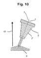
- the fact that the realignment of the axis to a change of position between the area of influence of the tool and the one to be machined Can lead to a block of material, thereby taking into account that depending on the geometric shape of the Area of influence of the tool a recalculation of the first Guideway is made.
- the Approximation surface can be determined, for example, by in CAD systems common area pieces, as Structures based on solid geometries or determined by point grids be that, since a proportionate for collision avoidance rough tolerance can be allowed, the calculation significantly simplify and speed up the overlap. Since the tool is often rotationally symmetrical around the axis and the tool holder compared to the actual one Machining tools mostly have a larger diameter has conical approximation surfaces that differs from the area of influence of the tool from tapering towards the tool holder and extend this enclosing.
- Axis 1 represents the rotational symmetry axis of both the conical tool holder 3 as well as the long cylindrical tool shank 4.
- the three tools 2 shown differ from each other only in terms of the shape of their on Tool shaft 4 opposite free end trained Area of action 5, 5 'or 5 "for the material-removing Engagement with a block of material indicated schematically in FIG. 2 6 is determined. This is how the tool is 2 of Fig.
- FIG. 1 (b) around an end mill in which the long cylindrical tool shank 4 at its free end Formation of the area of action 5 'a radially directed End surface has.
- Fig. 1 (a) is a radius cutter shown, in which in contrast to the end mill of Fig. 1 (b) the transition between the end face and the tool shank 4 at its free end to form the engagement area 5 rounded with a predetermined corner radius is.
- 1 (c) shows a ball milling cutter, the tool shank 4 at the free end to form the area of influence 5 "is hemispherical rounded.
- the tool 2 is part of a five-axis milling machine, not shown, by means of which it can simultaneously be pivoted along three mutually orthogonal location coordinates x, y, z in translation and about two mutually orthogonal pivot axes.
- the milling machine has a CNC control that by Process NC programs provided by cam systems and thereby a desired working movement of the milling tool 2 can perform.
- first guideways 7 in planes Track areas calculated.
- Fig. 3 is a portion of such first guideway 7 in orthogonal supervision their flat track surface 8 shown. 3 also leaves the cross section through the tool shank 4 and through the processing surface pieces 9, 9 'of the material block that have already been created 6 recognize.
- the first one in FIG Guideway 7 is only a smoothed path, while the reference number 10 indicates small guide arches, with which the area of action 5, 5 'or 5 "of the tool shank 4 swings out compared to the smoothed guideway shape 7 and returns.
- FIG. 4 An orthogonal top view is also shown in FIG. 4 a web surface 8 with a section running therein a first guideway 7 shown.
- the first guideway 7 becomes a tangent to the direction first guideway 7 orthogonal at the point 11 concerned Distance vector 12 determined with a predetermined length d.
- the opposite of point 11 of the first guideway End points 13 of the distance vectors 12 thus determine the geometric location 14 of all points from the first Guide path 7 have the predetermined distance d.
- the point-by-point calculation can be narrow Areas of curvature of the first guideway 7 shown in FIG. 4 Dotted sections 15 result, but the Distance requirement with regard to the entire first guideway 7 do not meet and that based on their Intersection 16 are eliminated, so that the applicable one geometric location 14 as the remaining connected components is obtained.
- the Geometric formed to define the second guideway 17 Location 14 in the area of narrow curvatures of the first guideway 7 kinks, d. H. non-differentiable digits 16, can have.
- the parameterization formed according to FIG. 6 supplies the second guideway 17 as a function of time single derivation the feed rate along the second guideway 17, the acceleration with two derivation and the jerk if the lead is derived three times.
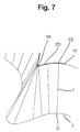
- Occurrence of an undesirably high jerkiness on the Avoiding points 16 becomes the second guideway according to FIG. 7 17 at least in the vicinity of these locations 16 approximated by an approximation curve 23, which as a result their differentiability causes a jerk reduction.
- approximation curves 23 cubic spline functions suitable.
Landscapes
- Engineering & Computer Science (AREA)
- Manufacturing & Machinery (AREA)
- Human Computer Interaction (AREA)
- Physics & Mathematics (AREA)
- General Physics & Mathematics (AREA)
- Automation & Control Theory (AREA)
- Numerical Control (AREA)
- Finish Polishing, Edge Sharpening, And Grinding By Specific Grinding Devices (AREA)
- Automatic Control Of Machine Tools (AREA)
- Milling, Broaching, Filing, Reaming, And Others (AREA)
- Grinding And Polishing Of Tertiary Curved Surfaces And Surfaces With Complex Shapes (AREA)
- Turning (AREA)
Abstract
Description
- Fig. 1 (a), (b) und (c)
- schematische Ansichten von Fräswerkzeugen mit unterschiedlich geformten Einwirkungs- bereichen
- Fig. 2
- eine schematische Darstellung des Fräs- werkzeuges bei der Bearbeitung einer Kavi- tät
- Fig. 3
- eine ausschnittsweise Aufsicht auf eine Bahnfläche und eine darin verlaufende er- ste Führungsbahn des Fräswerkzeugs,
- Fig. 4
- eine Darstellung zur Erläuterung der Be- stimmung einer zweiten Führungsbahn
- Fig. 5
- eine schematische Ansicht der Lage des Fräswerkzeugs in bezug auf die beiden Füh- rungsbahnen
- Fig. 6
- ein Schema zur Erläuterung des Synchron- laufs längs der ersten und der zweiten Führungsbahn
- Fig. 7
- ein Schema zur Erläuterung einer ruckmin- dernden Approximation der zweiten Füh- rungsbahn
- Fig. 8 (a), (b) und (c)
- schematische Darstellungen verschiedener Approximationsflächen für die geometrische Form des Werkzeugs
- Fig. 9
- eine schematische Darstellung einer Neu- ausrichtung der Achse des Werkzeugs zur Kollisionsvermeidung und
- Fig. 10
- eine schematische Darstellung zur Erläute- rung der Nachberechnung der ersten Füh- rungsbahn nach einer Neuausrichtung der Achse.
- 1
- Achse
- 2, 2'
- Werkzeug
- 3
- Werkzeughalter
- 4
- Werkzeugschaft
- 5, 5', 5"
- Einwirkungsbereich
- 6
- Materialblock
- 7
- erste Führungsbahn
- 8
- Bahnfläche
- 9, 9'
- Oberflächenstücke
- 10
- Führungsbögen
- 11
- Punkt der ersten Führungsbahn
- 12
- Abstandsvektor
- 13
- Endpunkt
- 14
- geometrischer Ort
- 15
- Abschnitte
- 16
- Schnittpunkt
- 17
- zweite Führungsbahn
- 19
- Flächennormale
- 20
- Ortsvektor
- 21
- Schnittpunkte
- 22
- Punkt
- 23
- Approximationskurve
- 24
- Überschneidung
- 25, 25'
- Approximationsfläche
- 26, 26', 26"
- Radien
Claims (9)
- Verfahren zum Steuern der Arbeitsbewegung eines Werkzeugs (2) zur materialabtragenden Bearbeitung eines Materialblocks (6) gemäß einer vorgegebenen Werkstücksform, bei dem ein zur materialabtragenden Einwirkung auf den Materialblock (6) dienender Einwirkungsbereich (5, 5', 5") des Werkzeugs (2) längs einer sich in einer im wesentlichen ebenen Bahnfläche (8) erstreckenden ersten Führungsbahn (7) mit einer bestimmten Ausrichtung einer die erste Führungsbahn (7) schneidenden Achse (1) des Werkzeugs (2) in bezug auf die Bahnfläche (8) bewegt wird, dadurch gekennzeichnet, daß ein von der ersten Führungsbahn (7) beabstandeter Punkt der Achse (1) des Werkzeugs (2) auf einer vorgegebenen zweiten Führungsbahn (17) geführt wird.
- Verfahren nach Anspruch 1, dadurch gekennzeichnet, daß der zur Bahnfläche (8) der ersten Führungsbahn (7) orthogonale Abstand (dz) der zweiten Führungsbahn (17) konstant ist.
- Verfahren nach Anspruch 1 oder 2, dadurch gekennzeichnet, daß die zweite Führungsbahn (17) als der um den zur Bahnfläche (8) der ersten Führungsbahn (7) orthogonalen Abstand (dz) des von der zweiten Führungsbahn geführten Punktes der Achse (1) des Werkzeugs (2) verschobene geometrische Ort (14) aller Punkte (13), die von der ersten Führungsbahn (7) in deren Bahnfläche (8) einen vorgegebenen Abstand (d) aufweisen, bestimmt wird.
- Verfahren nach einem der Ansprüche 1 bis 3, dadurch gekennzeichnet, daß zu jedem Schnittpunkt (21) der Achse (1) des Werkzeugs (2) mit der ersten Führungsbahn (7) der dazu den kleinsten Abstand aufweisende Punkt (22) der zweiten Führungsbahn (17) als auf der zweiten Führungsbahn (17) geführter Punkt der Achse (1) bestimmt wird.
- Verfahren nach einem der Ansprüche 1 bis 4, dadurch gekennzeichnet, daß der Schnittpunkt (21) der Achse (1) mit der ersten Führungsbahn (7) längs dieser mit gleichförmiger Geschwindigkeit bewegt und die zweite Führungsbahn (17) durch eine Approximationskurve (23) angenähert wird, längs der sich der darauf geführte Punkt (22) der Achse (1) des Werkzeugs (2) ruckarm mitbewegt.
- Verfahren zum Steuern der Arbeitsbewegung eines Werkzeugs (2) zur materialabtragenden Bearbeitung eines Materialblocks (6) gemäß einer vorgegebenen Werkstücksform, bei dem ein zur materialabtragenden Einwirkung auf den Materialblock (6) dienender Einwirkungsbereich (5, 5', 5") des Werkzeugs (2) längs einer sich in einer im wesentlichen ebenen Bahnfläche (8) erstreckenden ersten Führungsbahn (7) mit einer bestimmten Ausrichtung einer die erste Führungsbahn (7) schneidenden Achse (1) des Werkzeugs (2) in bezug auf die Bahnfläche (8) bewegt wird, insbesondere nach einem der Ansprüche 1 bis 5, dadurch gekennzeichnet, daß für jede Position des Werkzeugs (2) auf der ersten Führungsbahn (7) und die jeweils zugehörige Ausrichtung seiner Achse (1) die Relativlage zwischen der geometrischen Form des Werkzeugs (2) und der jeweiligen Werkstücksform vorausberechnet und im Fall einer außerhalb des Eingriffsbereichs (5, 5', 5") des Werkzeugs (2) liegenden Überschneidung (24) zwischen den beiden Formen eine Kollision vorausgesagt wird.
- Verfahren nach Anspruch 6, dadurch gekennzeichnet, daß bei einer Kollisionsvoraussage das Maximum des Winkels der Achse (1) gegenüber der Normalenrichtung (19) der Bahnfläche (8) der ersten Führungsbahn (7), bei dem gerade noch keine Kollision eintritt, berechnet und die Ausrichtung der Achse (1) gemäß diesem maximalen Winkel vorgegeben wird.
- Verfahren nach Anspruch 7, dadurch gekennzeichnet, daß in Abhängigkeit von der geometrischen Form des Einwirkungsbereichs (5, 5', 5") des Werkzeugs (2) eine Nachberechnung der ersten Führungsbahn (7) vorgenommen wird.
- Verfahren nach einem der Ansprüche 6 bis 8, dadurch gekennzeichnet, daß bei der Berechnung die geometrische Form des Werkzeugs (2) durch eine das Werkzeug (2) radial umschließende Approximationsfläche (25, 25', 25") ersetzt wird.
Priority Applications (9)
| Application Number | Priority Date | Filing Date | Title |
|---|---|---|---|
| DE19846426A DE19846426A1 (de) | 1998-10-08 | 1998-10-08 | Verfahren zum Steuern der Arbeitsbewegung eines Werkzeugs zur materialabtragenden Bearbeitung eines Materialblocks |
| AT00107685T ATE333671T1 (de) | 1998-10-08 | 2000-04-10 | Verfahren zum steuern der arbeitsbewegung eines werkzeugs zur materialabtragenden bearbeitung eines materialblocks |
| DE50013188T DE50013188D1 (de) | 1998-10-08 | 2000-04-10 | Verfahren zum Steuern der Arbeitsbewegung eines Werkzeugs zur materialabtragenden Bearbeitung eines Materialblocks |
| EP00107685A EP1146408B1 (de) | 1998-10-08 | 2000-04-10 | Verfahren zum Steuern der Arbeitsbewegung eines Werkzeugs zur materialabtragenden Bearbeitung eines Materialblocks |
| CNB018009018A CN1303487C (zh) | 1998-10-08 | 2001-04-11 | 将导引工具运动的方法作为切削加工材料块过程的一部分 |
| US09/829,921 US6632053B2 (en) | 1998-10-08 | 2001-04-11 | Method of directing the movement of a tool as part of a process to remove material from a block of material |
| AU52476/01A AU5247601A (en) | 1998-10-08 | 2001-04-11 | Method of directing the movement of a tool as part of a process to remove material from a block of material |
| JP2001576231A JP2003531422A (ja) | 1998-10-08 | 2001-04-11 | 材料片から材料を除去する工程の一部として工具の動作を指示する方法 |
| PCT/IB2001/000792 WO2001078943A2 (en) | 1998-10-08 | 2001-04-11 | Method of directing the movement of a tool as part of a process to remove material from a block of material |
Applications Claiming Priority (3)
| Application Number | Priority Date | Filing Date | Title |
|---|---|---|---|
| DE19846426A DE19846426A1 (de) | 1998-10-08 | 1998-10-08 | Verfahren zum Steuern der Arbeitsbewegung eines Werkzeugs zur materialabtragenden Bearbeitung eines Materialblocks |
| EP00107685A EP1146408B1 (de) | 1998-10-08 | 2000-04-10 | Verfahren zum Steuern der Arbeitsbewegung eines Werkzeugs zur materialabtragenden Bearbeitung eines Materialblocks |
| US19610500P | 2000-04-11 | 2000-04-11 |
Publications (2)
| Publication Number | Publication Date |
|---|---|
| EP1146408A1 true EP1146408A1 (de) | 2001-10-17 |
| EP1146408B1 EP1146408B1 (de) | 2006-07-19 |
Family
ID=27438867
Family Applications (1)
| Application Number | Title | Priority Date | Filing Date |
|---|---|---|---|
| EP00107685A Expired - Lifetime EP1146408B1 (de) | 1998-10-08 | 2000-04-10 | Verfahren zum Steuern der Arbeitsbewegung eines Werkzeugs zur materialabtragenden Bearbeitung eines Materialblocks |
Country Status (8)
| Country | Link |
|---|---|
| US (1) | US6632053B2 (de) |
| EP (1) | EP1146408B1 (de) |
| JP (1) | JP2003531422A (de) |
| CN (1) | CN1303487C (de) |
| AT (1) | ATE333671T1 (de) |
| AU (1) | AU5247601A (de) |
| DE (2) | DE19846426A1 (de) |
| WO (1) | WO2001078943A2 (de) |
Cited By (4)
| Publication number | Priority date | Publication date | Assignee | Title |
|---|---|---|---|---|
| WO2001078943A3 (en) * | 1998-10-08 | 2002-07-18 | Open Mind Software Technologie | Method of directing the movement of a tool as part of a process to remove material from a block of material |
| WO2005005083A1 (de) * | 2003-07-08 | 2005-01-20 | Mtu Aero Engines Gmbh | Fräsverfahren zur fertigung von bauteilen |
| WO2014016397A1 (de) * | 2012-07-27 | 2014-01-30 | Open Mind Technologies Ag | Verfahren zur teilweisen oder vollständigen bearbeitung einer beliebigen kavität |
| CN104570951A (zh) * | 2013-10-23 | 2015-04-29 | 发那科株式会社 | 刀具路径曲线化装置以及刀具路径曲线化方法 |
Families Citing this family (46)
| Publication number | Priority date | Publication date | Assignee | Title |
|---|---|---|---|---|
| DE10031441B4 (de) * | 2000-06-28 | 2006-10-12 | Open Mind Technologies Ag | Verfahren zum Steuern der Arbeitsbewegung eines Fräswerkzeugs |
| DE10144508C9 (de) * | 2001-09-10 | 2018-06-28 | Open Mind Technologies Ag | Verfahren zur Steuerung von Relativbewegungen eines Werkzeuges gegen ein Werkstück |
| DE10322340B4 (de) | 2003-05-17 | 2006-09-14 | Mtu Aero Engines Gmbh | Verfahren und Vorrichtung zum Fräsen von Freiformflächen |
| DE10327623B4 (de) * | 2003-06-19 | 2006-07-13 | Mtu Aero Engines Gmbh | Fräsverfahren zur Fertigung von Bauteilen |
| JP4362095B2 (ja) * | 2004-08-20 | 2009-11-11 | オークマ株式会社 | 数値制御装置 |
| DE102005022036A1 (de) * | 2005-05-09 | 2006-11-16 | Lemuth Gmbh | Montagekopf, insbesondere zur Montage von Glasscheiben in Rahmen |
| US7272463B2 (en) * | 2005-05-24 | 2007-09-18 | General Electric Company | Gouge and interference avoidance in surface contouring |
| US7881909B2 (en) * | 2005-07-21 | 2011-02-01 | The Boeing Company | Computerized tool and method for the automated creation of a cutter ramp curve |
| GB2436079A (en) * | 2006-03-16 | 2007-09-19 | Guy Satchwell | Method of manufacturing three-dimensional signage |
| JP4943173B2 (ja) * | 2007-02-06 | 2012-05-30 | 東芝機械株式会社 | スライドコア穴の加工方法およびスライドコア穴加工に用いる計測・補正システム |
| DE102007059568A1 (de) * | 2007-12-11 | 2009-06-18 | Mtu Aero Engines Gmbh | Tauchfräsverfahren |
| DE102008033130B3 (de) * | 2008-07-15 | 2010-02-11 | Open Mind Technologies Ag | Verfahren zur Herstellung eines Fertigteils aus einem Rohteil mittels eines Fräswerkzeuges |
| JP4607993B2 (ja) * | 2008-10-27 | 2011-01-05 | ファナック株式会社 | 5軸加工機の数値制御方法 |
| JP5426153B2 (ja) * | 2008-12-17 | 2014-02-26 | ファナック株式会社 | 回転軸を有する工作機械用の数値制御装置 |
| US8538574B2 (en) * | 2009-04-02 | 2013-09-17 | Dmg Electronics Gmbh | Method and apparatus for generating control data for controlling a tool on a machine tool |
| JP5431987B2 (ja) * | 2010-01-29 | 2014-03-05 | Dmg森精機株式会社 | 工作機械の制御装置 |
| US9946245B2 (en) | 2011-07-25 | 2018-04-17 | Celeritive Technologies, Inc. | Non-concentric milling |
| EP2590144B1 (de) | 2011-11-03 | 2018-10-24 | Dassault Systèmes | Entwurf eines modellierten, von Dexeln dargestellten Volumens |
| EP2590142B1 (de) | 2011-11-03 | 2018-03-14 | Dassault Systèmes | Entwurf eines modellierten, von Dexeln dargestellten Volumens |
| EP2590143B1 (de) * | 2011-11-03 | 2018-10-24 | Dassault Systèmes | Simulation der Verarbeitung eines Werkstücks |
| TWI453078B (zh) * | 2011-11-28 | 2014-09-21 | Nat Univ Tsing Hua | 一種五軸曲面側銑加工系統及其路徑規劃方法 |
| DE102011088864A1 (de) * | 2011-12-16 | 2013-06-20 | Cdp Bharat Forge Gmbh | Kaltkalibrierpresse für Monoblockschalträder mit einbaufertiger Kupplungsverzahnung |
| US10022833B2 (en) * | 2012-05-03 | 2018-07-17 | Celeritive Technologies, Inc. | High performance multi-axis milling |
| US9046888B2 (en) * | 2012-06-27 | 2015-06-02 | Mitsubishi Electric Research Laboratories, Inc. | Method and system for detouring around features cut from sheet materials with a laser cutter according to a pattern |
| US9329592B2 (en) * | 2012-11-27 | 2016-05-03 | Pratt & Whitney Canada Corp. | Methods and systems for calculation of feedrate |
| US9292626B2 (en) * | 2012-12-10 | 2016-03-22 | Palo Alto Research Center Incorporated | Computer numerical control (CNC) machining tool and method for controlling a CNC machining tool |
| US9869990B1 (en) * | 2013-09-12 | 2018-01-16 | D.P. Technology Corp. | Automatic positioning movement calculator |
| EP2902859B1 (de) * | 2013-09-27 | 2020-03-11 | Siemens Aktiengesellschaft | Steuereinrichtung mit integriertem Optimierer |
| JP6442861B2 (ja) * | 2014-04-24 | 2018-12-26 | スター精密株式会社 | 工作機械、及び、解釈実行プログラム |
| WO2016009502A1 (ja) * | 2014-07-16 | 2016-01-21 | ヤマザキマザック 株式会社 | 旋削加工制御装置、および旋削加工支援プログラム |
| JP5855715B1 (ja) * | 2014-08-07 | 2016-02-09 | ファナック株式会社 | 工作機械 |
| EP3040797B1 (de) | 2014-12-31 | 2020-10-28 | Dassault Systèmes | Simulierung der Verarbeitung eines Werkstücks |
| DE102015104679C5 (de) * | 2015-03-26 | 2023-09-07 | Open Mind Technologies Ag | Verfahren zur materialabtragenden Bearbeitung von ebenen Flächen eines Werkstückes |
| JP6612592B2 (ja) * | 2015-11-12 | 2019-11-27 | ローランドディー.ジー.株式会社 | 箔転写装置で使用するデータを作成するためのプログラム、箔転写装置、箔転写方法 |
| US10564626B2 (en) | 2016-01-29 | 2020-02-18 | Sandvik Intellectual Property Ab | Planning of computer numerical control (CNC) machining operations with the aid of a digital computer |
| US10271021B2 (en) * | 2016-02-29 | 2019-04-23 | Microsoft Technology Licensing, Llc | Vehicle trajectory determination to stabilize vehicle-captured video |
| DE102016117932B4 (de) * | 2016-09-22 | 2020-06-10 | Open Mind Technologies Ag | Verfahren zur materialabtragenden Bearbeitung von Verrundungsflächen eines Werkstückes |
| CN108415375B (zh) * | 2018-02-07 | 2019-12-27 | 大连理工大学 | 一种用于多主轴加工的电子凸轮控制方法 |
| DE102018123363B4 (de) * | 2018-09-24 | 2021-01-07 | Bystronic Laser Ag | Verfahren zur Kollisionsvermeidung und Laserbearbeitungsmaschine |
| DE102018125620A1 (de) * | 2018-10-16 | 2020-04-16 | Schuler Pressen Gmbh | Verfahren und Vorrichtung zum Schneiden einer Blechplatine aus einem kontinuierlich geförderten Blechband |
| EP3680738A1 (de) | 2019-01-14 | 2020-07-15 | Siemens Aktiengesellschaft | Kollisionsprüfung auf basis höherwertiger geometrie |
| JP6758441B2 (ja) * | 2019-02-18 | 2020-09-23 | 株式会社アマダ | レーザ加工機、レーザ加工方法、及び加工プログラム作成装置 |
| DE102021116899A1 (de) * | 2021-06-30 | 2023-01-05 | Messer Cutting Systems Gmbh | Verfahren zur thermischen Bearbeitung eines Werkstücks mit einer thermischen Bearbeitungsmaschine |
| CN114239140B (zh) * | 2021-12-15 | 2024-07-12 | 成都飞机工业(集团)有限责任公司 | 一种飞机结构件腹板铣削表面粗糙度预测方法 |
| CN115592520B (zh) * | 2022-11-07 | 2024-08-06 | 重庆大学 | 一种叶片极薄边缘机器人高精度磨抛轨迹规划方法 |
| CN120898184A (zh) * | 2023-03-30 | 2025-11-04 | 发那科株式会社 | 信息生成装置和信息显示装置 |
Citations (5)
| Publication number | Priority date | Publication date | Assignee | Title |
|---|---|---|---|---|
| US4503373A (en) * | 1980-10-29 | 1985-03-05 | Fanuc Ltd. | Numerical control system |
| GB2192075A (en) * | 1986-06-26 | 1987-12-31 | Toshiba Machine Co Ltd | Generating toolpath in cadcam system |
| US4789931A (en) * | 1986-09-04 | 1988-12-06 | Sony Corporation | System for automatically generating tool path data for automatic machining center |
| EP0543141A1 (de) * | 1991-11-19 | 1993-05-26 | Kabushiki Kaisha F A Labo | Verfahren zur dreidimensionalen Bearbeitung |
| WO1996008752A2 (en) * | 1994-09-02 | 1996-03-21 | Cimplus, Inc. | Interactive machine control system and method |
Family Cites Families (26)
| Publication number | Priority date | Publication date | Assignee | Title |
|---|---|---|---|---|
| US3774279A (en) * | 1972-06-27 | 1973-11-27 | H Hunter | Radius cutter |
| JPS57166606A (en) * | 1981-04-04 | 1982-10-14 | Fanuc Ltd | Numerical control working method |
| DE3113970A1 (de) * | 1981-04-07 | 1982-11-04 | Dr. Johannes Heidenhain Gmbh, 8225 Traunreut | Numerische bahnsteuerung fuer eine werkzeugmaschine |
| JPS58163001A (ja) * | 1982-03-23 | 1983-09-27 | Toyoda Mach Works Ltd | 干渉チエツク機能を備えた数値制御装置 |
| JPS59214539A (ja) * | 1983-05-17 | 1984-12-04 | Fanuc Ltd | 工具干渉チエツク方法 |
| US4674928A (en) * | 1984-06-25 | 1987-06-23 | George Lyman | Milling machine controller |
| JPH0276004A (ja) * | 1988-09-13 | 1990-03-15 | Fanuc Ltd | 荒加工用ncデータ作成方法 |
| JPH02113305A (ja) * | 1988-10-24 | 1990-04-25 | Fanuc Ltd | スプライン補間方法 |
| US5043906A (en) * | 1989-11-24 | 1991-08-27 | Ford Motor Company | Absolute gouge avoidance for computer-aided control of cutter paths |
| US5107436A (en) * | 1990-04-06 | 1992-04-21 | Northern Research & Engineering Corp. | Method for generating a tool course for a cutting tool |
| JP2667563B2 (ja) * | 1990-08-09 | 1997-10-27 | ファナック株式会社 | 工具軸方向計算方法 |
| US5378091A (en) * | 1992-06-17 | 1995-01-03 | Makino Milling Machine Co., Ltd. | Method and apparatus for machining a workpiece |
| US5508596A (en) * | 1993-10-07 | 1996-04-16 | Omax Corporation | Motion control with precomputation |
| JPH0852638A (ja) * | 1994-08-15 | 1996-02-27 | Toshiba Mach Co Ltd | 干渉チェック方法および加工プログラムチェック方法および加工適否チェック方法 |
| JP3599800B2 (ja) * | 1994-10-24 | 2004-12-08 | 東芝機械株式会社 | 数値制御工作機械の主軸法線方向制御方法 |
| US5595391A (en) * | 1995-04-18 | 1997-01-21 | The Board Of Governors Of Wayne State University | Relating to tapered connections |
| JPH08305427A (ja) * | 1995-04-28 | 1996-11-22 | Honda Motor Co Ltd | 5軸加工機用面加工データの作成方法 |
| JPH0938843A (ja) * | 1995-07-26 | 1997-02-10 | Toyota Motor Corp | 切削加工方法および切削加工用移動経路データの作成装置 |
| DE19529547A1 (de) * | 1995-08-11 | 1997-02-13 | Zeiss Carl Fa | Verfahren zur Steuerung von Koordinatenmeßgeräten |
| WO1997036216A1 (en) * | 1996-03-26 | 1997-10-02 | Toyota Jidosha Kabushiki Kaisha | Method and apparatus for preparing data on tool moving path, and machining method and system |
| JPH1020919A (ja) * | 1996-06-28 | 1998-01-23 | Toyota Central Res & Dev Lab Inc | 移動体経路生成方法及びその装置 |
| JPH10177406A (ja) * | 1996-12-17 | 1998-06-30 | Fanuc Ltd | 5軸加工機の制御装置 |
| JPH10240320A (ja) * | 1997-03-03 | 1998-09-11 | Toyoda Mach Works Ltd | Ncデータ作成装置 |
| JPH10337636A (ja) * | 1997-06-09 | 1998-12-22 | Fanuc Ltd | 5軸加工機の制御装置 |
| US6311100B1 (en) * | 1998-09-14 | 2001-10-30 | Mass. Institute Of Technology | Tool path generator for computer aided manufacturing |
| DE19846426A1 (de) * | 1998-10-08 | 2000-04-13 | Open Mind Software Technologie | Verfahren zum Steuern der Arbeitsbewegung eines Werkzeugs zur materialabtragenden Bearbeitung eines Materialblocks |
-
1998
- 1998-10-08 DE DE19846426A patent/DE19846426A1/de not_active Withdrawn
-
2000
- 2000-04-10 DE DE50013188T patent/DE50013188D1/de not_active Expired - Lifetime
- 2000-04-10 EP EP00107685A patent/EP1146408B1/de not_active Expired - Lifetime
- 2000-04-10 AT AT00107685T patent/ATE333671T1/de not_active IP Right Cessation
-
2001
- 2001-04-11 US US09/829,921 patent/US6632053B2/en not_active Expired - Lifetime
- 2001-04-11 CN CNB018009018A patent/CN1303487C/zh not_active Expired - Fee Related
- 2001-04-11 AU AU52476/01A patent/AU5247601A/en not_active Abandoned
- 2001-04-11 JP JP2001576231A patent/JP2003531422A/ja active Pending
- 2001-04-11 WO PCT/IB2001/000792 patent/WO2001078943A2/en not_active Ceased
Patent Citations (5)
| Publication number | Priority date | Publication date | Assignee | Title |
|---|---|---|---|---|
| US4503373A (en) * | 1980-10-29 | 1985-03-05 | Fanuc Ltd. | Numerical control system |
| GB2192075A (en) * | 1986-06-26 | 1987-12-31 | Toshiba Machine Co Ltd | Generating toolpath in cadcam system |
| US4789931A (en) * | 1986-09-04 | 1988-12-06 | Sony Corporation | System for automatically generating tool path data for automatic machining center |
| EP0543141A1 (de) * | 1991-11-19 | 1993-05-26 | Kabushiki Kaisha F A Labo | Verfahren zur dreidimensionalen Bearbeitung |
| WO1996008752A2 (en) * | 1994-09-02 | 1996-03-21 | Cimplus, Inc. | Interactive machine control system and method |
Cited By (7)
| Publication number | Priority date | Publication date | Assignee | Title |
|---|---|---|---|---|
| WO2001078943A3 (en) * | 1998-10-08 | 2002-07-18 | Open Mind Software Technologie | Method of directing the movement of a tool as part of a process to remove material from a block of material |
| US6632053B2 (en) * | 1998-10-08 | 2003-10-14 | Open Mind Software Technologies Gmbh | Method of directing the movement of a tool as part of a process to remove material from a block of material |
| WO2005005083A1 (de) * | 2003-07-08 | 2005-01-20 | Mtu Aero Engines Gmbh | Fräsverfahren zur fertigung von bauteilen |
| US7832968B2 (en) | 2003-07-08 | 2010-11-16 | Mtu Aero Engines Gmbh | Milling method for the production of components |
| WO2014016397A1 (de) * | 2012-07-27 | 2014-01-30 | Open Mind Technologies Ag | Verfahren zur teilweisen oder vollständigen bearbeitung einer beliebigen kavität |
| CN104570951A (zh) * | 2013-10-23 | 2015-04-29 | 发那科株式会社 | 刀具路径曲线化装置以及刀具路径曲线化方法 |
| CN104570951B (zh) * | 2013-10-23 | 2018-10-02 | 发那科株式会社 | 刀具路径曲线化装置以及刀具路径曲线化方法 |
Also Published As
| Publication number | Publication date |
|---|---|
| WO2001078943A3 (en) | 2002-07-18 |
| CN1430741A (zh) | 2003-07-16 |
| WO2001078943A2 (en) | 2001-10-25 |
| CN1303487C (zh) | 2007-03-07 |
| ATE333671T1 (de) | 2006-08-15 |
| EP1146408B1 (de) | 2006-07-19 |
| DE19846426A1 (de) | 2000-04-13 |
| JP2003531422A (ja) | 2003-10-21 |
| DE50013188D1 (de) | 2006-08-31 |
| AU5247601A (en) | 2001-10-30 |
| US6632053B2 (en) | 2003-10-14 |
| US20010048857A1 (en) | 2001-12-06 |
Similar Documents
| Publication | Publication Date | Title |
|---|---|---|
| EP1146408B1 (de) | Verfahren zum Steuern der Arbeitsbewegung eines Werkzeugs zur materialabtragenden Bearbeitung eines Materialblocks | |
| DE69232294T2 (de) | Numerische Steuerungseinheit | |
| EP2221693B1 (de) | Verfahren und Vorrichtung zum Erzeugen von Steuerdaten zum Steuern eines Werkzeugs an einer zumindest 5 Achsen umfassenden Werkzeugmaschine | |
| EP0467892B1 (de) | Verfahren zur formgebenden bearbeitung von werkstücken | |
| DE102015013582B4 (de) | Numerische Steuervorrichtung | |
| DE69202323T2 (de) | Verfahren zur dreidimensionalen Bearbeitung. | |
| DE102016012634B4 (de) | Numerische Steuerung mit krümmungs- und krümmungsänderungsabhängiger Geschwindigkeitssteuerung | |
| EP1040396B1 (de) | Verfahren zum abtragenden bearbeiten von werkstücken | |
| EP3317734B1 (de) | Steuerungsverfahren für die bewegung eines werkzeugs und steuerungsvorrichtung | |
| DE3820566C2 (de) | Verfahren zum Ermitteln einer Bewegungsbahn eines Bearbeitungswerkzeugs einer von einer numerischen Steuervorrichtung gesteuerten Werkzeugmaschine | |
| EP3221758A1 (de) | Verfahren zur bearbeitung eines werkstücks mittels eines spanabhebenden werkzeugs auf einer nc-gesteuerten werkzeugmaschine | |
| EP3824360B1 (de) | Verfahren zum ermitteln einer grobbahn aus einer vorgegebenen kontur | |
| EP3582043A1 (de) | Verfahren, numerische steuereinrichtung sowie werkzeugmaschine zur bearbeitung eines werkstücks | |
| DE102017006986B4 (de) | Numerische Steuerung und Bewegungssteuerverfahren für ein Werkzeug | |
| EP1307318B1 (de) | Generierung von fräsprogrammen zur umlaufenden fünfachsigen bearbeitung von turbinenschaufeln | |
| EP1369759B1 (de) | Bahnsteuerungsverfahren einer numerisch gesteuerten Maschine | |
| DE10144508C5 (de) | Verfahren zur Steuerung von Relativbewegungen eines Werkzeuges gegen ein Werkstück | |
| DE10208411B4 (de) | Verfahren zur Bearbeitung von Werkstücken mit geraden Oberflächenausnehmungen | |
| EP0335366B1 (de) | Verfahren zur numerischen Bahnsteuerung für Elektroerodiermaschinen | |
| EP1671193B1 (de) | Verfahren zur automatischen optimierung des materialabtrags bei der spanenden bearbeitung eines werkstücks | |
| DE102006001496B4 (de) | System und Verfahren zur Bestimmung geometrischer Veränderungen eines Werkstücks | |
| EP4246256A1 (de) | Werkstückbearbeitung mit optimierter spindeldrehzahl in abhängigkeit eines schnittpunktes | |
| DE69505088T2 (de) | Schneidplotter | |
| WO2022033761A1 (de) | Betriebsverfahren für eine werkzeugmaschine, computerprogrammprodukt, steuereinheit und werkzeugmaschine | |
| DE102012016676B4 (de) | Verfahren zur Schruppbearbeitung eines Werkstücks mit einer Mehrachs-Fräsmaschine |
Legal Events
| Date | Code | Title | Description |
|---|---|---|---|
| PUAI | Public reference made under article 153(3) epc to a published international application that has entered the european phase |
Free format text: ORIGINAL CODE: 0009012 |
|
| AK | Designated contracting states |
Kind code of ref document: A1 Designated state(s): AT BE CH CY DE DK ES FI FR GB GR IE IT LI LU MC NL PT SE |
|
| AX | Request for extension of the european patent |
Free format text: AL;LT;LV;MK;RO;SI |
|
| 17P | Request for examination filed |
Effective date: 20020417 |
|
| AKX | Designation fees paid |
Free format text: AT BE CH CY DE DK ES FI FR GB GR IE IT LI LU MC NL PT SE |
|
| 17Q | First examination report despatched |
Effective date: 20040528 |
|
| GRAP | Despatch of communication of intention to grant a patent |
Free format text: ORIGINAL CODE: EPIDOSNIGR1 |
|
| RAP1 | Party data changed (applicant data changed or rights of an application transferred) |
Owner name: OPEN MIND SOFTWARE TECHNOLOGIES GMBH |
|
| GRAS | Grant fee paid |
Free format text: ORIGINAL CODE: EPIDOSNIGR3 |
|
| GRAA | (expected) grant |
Free format text: ORIGINAL CODE: 0009210 |
|
| AK | Designated contracting states |
Kind code of ref document: B1 Designated state(s): AT BE CH CY DE DK ES FI FR GB GR IE IT LI LU MC NL PT SE |
|
| PG25 | Lapsed in a contracting state [announced via postgrant information from national office to epo] |
Ref country code: NL Free format text: LAPSE BECAUSE OF FAILURE TO SUBMIT A TRANSLATION OF THE DESCRIPTION OR TO PAY THE FEE WITHIN THE PRESCRIBED TIME-LIMIT Effective date: 20060719 Ref country code: IT Free format text: LAPSE BECAUSE OF FAILURE TO SUBMIT A TRANSLATION OF THE DESCRIPTION OR TO PAY THE FEE WITHIN THE PRESCRIBED TIME-LIMIT;WARNING: LAPSES OF ITALIAN PATENTS WITH EFFECTIVE DATE BEFORE 2007 MAY HAVE OCCURRED AT ANY TIME BEFORE 2007. THE CORRECT EFFECTIVE DATE MAY BE DIFFERENT FROM THE ONE RECORDED. Effective date: 20060719 Ref country code: FI Free format text: LAPSE BECAUSE OF FAILURE TO SUBMIT A TRANSLATION OF THE DESCRIPTION OR TO PAY THE FEE WITHIN THE PRESCRIBED TIME-LIMIT Effective date: 20060719 Ref country code: IE Free format text: LAPSE BECAUSE OF FAILURE TO SUBMIT A TRANSLATION OF THE DESCRIPTION OR TO PAY THE FEE WITHIN THE PRESCRIBED TIME-LIMIT Effective date: 20060719 |
|
| REG | Reference to a national code |
Ref country code: GB Ref legal event code: FG4D Free format text: NOT ENGLISH |
|
| REG | Reference to a national code |
Ref country code: CH Ref legal event code: EP |
|
| REG | Reference to a national code |
Ref country code: IE Ref legal event code: FG4D Free format text: LANGUAGE OF EP DOCUMENT: GERMAN |
|
| REF | Corresponds to: |
Ref document number: 50013188 Country of ref document: DE Date of ref document: 20060831 Kind code of ref document: P |
|
| PG25 | Lapsed in a contracting state [announced via postgrant information from national office to epo] |
Ref country code: DK Free format text: LAPSE BECAUSE OF FAILURE TO SUBMIT A TRANSLATION OF THE DESCRIPTION OR TO PAY THE FEE WITHIN THE PRESCRIBED TIME-LIMIT Effective date: 20061019 Ref country code: SE Free format text: LAPSE BECAUSE OF FAILURE TO SUBMIT A TRANSLATION OF THE DESCRIPTION OR TO PAY THE FEE WITHIN THE PRESCRIBED TIME-LIMIT Effective date: 20061019 |
|
| PG25 | Lapsed in a contracting state [announced via postgrant information from national office to epo] |
Ref country code: ES Free format text: LAPSE BECAUSE OF FAILURE TO SUBMIT A TRANSLATION OF THE DESCRIPTION OR TO PAY THE FEE WITHIN THE PRESCRIBED TIME-LIMIT Effective date: 20061030 |
|
| GBT | Gb: translation of ep patent filed (gb section 77(6)(a)/1977) |
Effective date: 20061020 |
|
| NLV1 | Nl: lapsed or annulled due to failure to fulfill the requirements of art. 29p and 29m of the patents act | ||
| REG | Reference to a national code |
Ref country code: IE Ref legal event code: FD4D |
|
| ET | Fr: translation filed | ||
| RAP2 | Party data changed (patent owner data changed or rights of a patent transferred) |
Owner name: OPEN MIND TECHNOLOGIES AG |
|
| PLBE | No opposition filed within time limit |
Free format text: ORIGINAL CODE: 0009261 |
|
| STAA | Information on the status of an ep patent application or granted ep patent |
Free format text: STATUS: NO OPPOSITION FILED WITHIN TIME LIMIT |
|
| 26N | No opposition filed |
Effective date: 20070420 |
|
| BERE | Be: lapsed |
Owner name: OPEN MIND SOFTWARE TECHNOLOGIES G.M.B.H. Effective date: 20070430 |
|
| PG25 | Lapsed in a contracting state [announced via postgrant information from national office to epo] |
Ref country code: BE Free format text: LAPSE BECAUSE OF NON-PAYMENT OF DUE FEES Effective date: 20070430 |
|
| PG25 | Lapsed in a contracting state [announced via postgrant information from national office to epo] |
Ref country code: GR Free format text: LAPSE BECAUSE OF FAILURE TO SUBMIT A TRANSLATION OF THE DESCRIPTION OR TO PAY THE FEE WITHIN THE PRESCRIBED TIME-LIMIT Effective date: 20061020 |
|
| PG25 | Lapsed in a contracting state [announced via postgrant information from national office to epo] |
Ref country code: AT Free format text: LAPSE BECAUSE OF NON-PAYMENT OF DUE FEES Effective date: 20070410 |
|
| PG25 | Lapsed in a contracting state [announced via postgrant information from national office to epo] |
Ref country code: MC Free format text: LAPSE BECAUSE OF NON-PAYMENT OF DUE FEES Effective date: 20070430 |
|
| PG25 | Lapsed in a contracting state [announced via postgrant information from national office to epo] |
Ref country code: CY Free format text: LAPSE BECAUSE OF FAILURE TO SUBMIT A TRANSLATION OF THE DESCRIPTION OR TO PAY THE FEE WITHIN THE PRESCRIBED TIME-LIMIT Effective date: 20060719 Ref country code: LU Free format text: LAPSE BECAUSE OF NON-PAYMENT OF DUE FEES Effective date: 20070410 |
|
| PG25 | Lapsed in a contracting state [announced via postgrant information from national office to epo] |
Ref country code: PT Free format text: LAPSE BECAUSE OF FAILURE TO SUBMIT A TRANSLATION OF THE DESCRIPTION OR TO PAY THE FEE WITHIN THE PRESCRIBED TIME-LIMIT Effective date: 20060719 |
|
| REG | Reference to a national code |
Ref country code: FR Ref legal event code: PLFP Year of fee payment: 17 |
|
| PGFP | Annual fee paid to national office [announced via postgrant information from national office to epo] |
Ref country code: GB Payment date: 20160422 Year of fee payment: 17 Ref country code: CH Payment date: 20160422 Year of fee payment: 17 |
|
| PGFP | Annual fee paid to national office [announced via postgrant information from national office to epo] |
Ref country code: FR Payment date: 20160422 Year of fee payment: 17 Ref country code: IT Payment date: 20160422 Year of fee payment: 17 |
|
| REG | Reference to a national code |
Ref country code: CH Ref legal event code: PL |
|
| GBPC | Gb: european patent ceased through non-payment of renewal fee |
Effective date: 20170410 |
|
| REG | Reference to a national code |
Ref country code: FR Ref legal event code: ST Effective date: 20171229 |
|
| PG25 | Lapsed in a contracting state [announced via postgrant information from national office to epo] |
Ref country code: FR Free format text: LAPSE BECAUSE OF NON-PAYMENT OF DUE FEES Effective date: 20170502 |
|
| PG25 | Lapsed in a contracting state [announced via postgrant information from national office to epo] |
Ref country code: GB Free format text: LAPSE BECAUSE OF NON-PAYMENT OF DUE FEES Effective date: 20170410 Ref country code: LI Free format text: LAPSE BECAUSE OF NON-PAYMENT OF DUE FEES Effective date: 20170430 Ref country code: CH Free format text: LAPSE BECAUSE OF NON-PAYMENT OF DUE FEES Effective date: 20170430 |
|
| PG25 | Lapsed in a contracting state [announced via postgrant information from national office to epo] |
Ref country code: IT Free format text: LAPSE BECAUSE OF NON-PAYMENT OF DUE FEES Effective date: 20170410 |
|
| REG | Reference to a national code |
Ref country code: DE Ref legal event code: R082 Ref document number: 50013188 Country of ref document: DE Ref country code: DE Ref legal event code: R082 Ref document number: 50013188 Country of ref document: DE Representative=s name: WUESTHOFF & WUESTHOFF, PATENTANWAELTE PARTG MB, DE |
|
| PGFP | Annual fee paid to national office [announced via postgrant information from national office to epo] |
Ref country code: DE Payment date: 20190425 Year of fee payment: 20 |
|
| REG | Reference to a national code |
Ref country code: DE Ref legal event code: R071 Ref document number: 50013188 Country of ref document: DE |