EP1146252A1 - Continuously variable transmission - Google Patents
Continuously variable transmission Download PDFInfo
- Publication number
- EP1146252A1 EP1146252A1 EP99949405A EP99949405A EP1146252A1 EP 1146252 A1 EP1146252 A1 EP 1146252A1 EP 99949405 A EP99949405 A EP 99949405A EP 99949405 A EP99949405 A EP 99949405A EP 1146252 A1 EP1146252 A1 EP 1146252A1
- Authority
- EP
- European Patent Office
- Prior art keywords
- speed ratio
- speed
- speed change
- continuously variable
- variable transmission
- Prior art date
- Legal status (The legal status is an assumption and is not a legal conclusion. Google has not performed a legal analysis and makes no representation as to the accuracy of the status listed.)
- Granted
Links
- 230000005540 biological transmission Effects 0.000 title claims abstract description 326
- 230000008859 change Effects 0.000 claims abstract description 366
- 230000007246 mechanism Effects 0.000 claims abstract description 84
- 238000001514 detection method Methods 0.000 claims description 26
- 230000001105 regulatory effect Effects 0.000 claims description 17
- 230000001276 controlling effect Effects 0.000 claims description 14
- 230000002829 reductive effect Effects 0.000 claims description 11
- 238000006073 displacement reaction Methods 0.000 claims description 10
- 230000002441 reversible effect Effects 0.000 claims description 8
- 239000002131 composite material Substances 0.000 abstract description 4
- 238000000034 method Methods 0.000 description 39
- 230000008569 process Effects 0.000 description 38
- 230000001133 acceleration Effects 0.000 description 18
- 238000005192 partition Methods 0.000 description 15
- 230000007935 neutral effect Effects 0.000 description 13
- 239000003921 oil Substances 0.000 description 13
- 230000003247 decreasing effect Effects 0.000 description 11
- 239000010720 hydraulic oil Substances 0.000 description 7
- 230000033228 biological regulation Effects 0.000 description 6
- 238000004519 manufacturing process Methods 0.000 description 5
- 238000010586 diagram Methods 0.000 description 4
- 230000009467 reduction Effects 0.000 description 4
- 230000035939 shock Effects 0.000 description 4
- 230000004048 modification Effects 0.000 description 3
- 238000012986 modification Methods 0.000 description 3
- 230000002093 peripheral effect Effects 0.000 description 3
- 238000010276 construction Methods 0.000 description 2
- 230000003467 diminishing effect Effects 0.000 description 2
- 239000000446 fuel Substances 0.000 description 2
- 230000002401 inhibitory effect Effects 0.000 description 2
- 230000009347 mechanical transmission Effects 0.000 description 2
- 238000003825 pressing Methods 0.000 description 2
- 238000004088 simulation Methods 0.000 description 2
- OAKJQQAXSVQMHS-UHFFFAOYSA-N Hydrazine Chemical compound NN OAKJQQAXSVQMHS-UHFFFAOYSA-N 0.000 description 1
- 230000015572 biosynthetic process Effects 0.000 description 1
- 238000005094 computer simulation Methods 0.000 description 1
- 230000000694 effects Effects 0.000 description 1
- 239000012530 fluid Substances 0.000 description 1
- 238000009499 grossing Methods 0.000 description 1
- 230000006872 improvement Effects 0.000 description 1
- 238000002955 isolation Methods 0.000 description 1
- 230000000670 limiting effect Effects 0.000 description 1
- 239000000463 material Substances 0.000 description 1
- 239000002184 metal Substances 0.000 description 1
- 239000000203 mixture Substances 0.000 description 1
- 239000010802 sludge Substances 0.000 description 1
- 230000000087 stabilizing effect Effects 0.000 description 1
- 238000011144 upstream manufacturing Methods 0.000 description 1
Images


Classifications
-
- F—MECHANICAL ENGINEERING; LIGHTING; HEATING; WEAPONS; BLASTING
- F16—ENGINEERING ELEMENTS AND UNITS; GENERAL MEASURES FOR PRODUCING AND MAINTAINING EFFECTIVE FUNCTIONING OF MACHINES OR INSTALLATIONS; THERMAL INSULATION IN GENERAL
- F16H—GEARING
- F16H61/00—Control functions within control units of change-speed- or reversing-gearings for conveying rotary motion ; Control of exclusively fluid gearing, friction gearing, gearings with endless flexible members or other particular types of gearing
- F16H61/38—Control of exclusively fluid gearing
- F16H61/40—Control of exclusively fluid gearing hydrostatic
- F16H61/46—Automatic regulation in accordance with output requirements
-
- B—PERFORMING OPERATIONS; TRANSPORTING
- B62—LAND VEHICLES FOR TRAVELLING OTHERWISE THAN ON RAILS
- B62D—MOTOR VEHICLES; TRAILERS
- B62D11/00—Steering non-deflectable wheels; Steering endless tracks or the like
- B62D11/02—Steering non-deflectable wheels; Steering endless tracks or the like by differentially driving ground-engaging elements on opposite vehicle sides
- B62D11/06—Steering non-deflectable wheels; Steering endless tracks or the like by differentially driving ground-engaging elements on opposite vehicle sides by means of a single main power source
- B62D11/10—Steering non-deflectable wheels; Steering endless tracks or the like by differentially driving ground-engaging elements on opposite vehicle sides by means of a single main power source using gearings with differential power outputs on opposite sides, e.g. twin-differential or epicyclic gears
- B62D11/14—Steering non-deflectable wheels; Steering endless tracks or the like by differentially driving ground-engaging elements on opposite vehicle sides by means of a single main power source using gearings with differential power outputs on opposite sides, e.g. twin-differential or epicyclic gears differential power outputs being effected by additional power supply to one side, e.g. power originating from secondary power source
- B62D11/18—Steering non-deflectable wheels; Steering endless tracks or the like by differentially driving ground-engaging elements on opposite vehicle sides by means of a single main power source using gearings with differential power outputs on opposite sides, e.g. twin-differential or epicyclic gears differential power outputs being effected by additional power supply to one side, e.g. power originating from secondary power source the additional power supply being supplied hydraulically
-
- F—MECHANICAL ENGINEERING; LIGHTING; HEATING; WEAPONS; BLASTING
- F16—ENGINEERING ELEMENTS AND UNITS; GENERAL MEASURES FOR PRODUCING AND MAINTAINING EFFECTIVE FUNCTIONING OF MACHINES OR INSTALLATIONS; THERMAL INSULATION IN GENERAL
- F16H—GEARING
- F16H47/00—Combinations of mechanical gearing with fluid clutches or fluid gearing
- F16H47/02—Combinations of mechanical gearing with fluid clutches or fluid gearing the fluid gearing being of the volumetric type
- F16H47/04—Combinations of mechanical gearing with fluid clutches or fluid gearing the fluid gearing being of the volumetric type the mechanical gearing being of the type with members having orbital motion
-
- F—MECHANICAL ENGINEERING; LIGHTING; HEATING; WEAPONS; BLASTING
- F16—ENGINEERING ELEMENTS AND UNITS; GENERAL MEASURES FOR PRODUCING AND MAINTAINING EFFECTIVE FUNCTIONING OF MACHINES OR INSTALLATIONS; THERMAL INSULATION IN GENERAL
- F16H—GEARING
- F16H61/00—Control functions within control units of change-speed- or reversing-gearings for conveying rotary motion ; Control of exclusively fluid gearing, friction gearing, gearings with endless flexible members or other particular types of gearing
- F16H61/38—Control of exclusively fluid gearing
- F16H61/40—Control of exclusively fluid gearing hydrostatic
- F16H61/46—Automatic regulation in accordance with output requirements
- F16H61/462—Automatic regulation in accordance with output requirements for achieving a target speed ratio
-
- B—PERFORMING OPERATIONS; TRANSPORTING
- B60—VEHICLES IN GENERAL
- B60K—ARRANGEMENT OR MOUNTING OF PROPULSION UNITS OR OF TRANSMISSIONS IN VEHICLES; ARRANGEMENT OR MOUNTING OF PLURAL DIVERSE PRIME-MOVERS IN VEHICLES; AUXILIARY DRIVES FOR VEHICLES; INSTRUMENTATION OR DASHBOARDS FOR VEHICLES; ARRANGEMENTS IN CONNECTION WITH COOLING, AIR INTAKE, GAS EXHAUST OR FUEL SUPPLY OF PROPULSION UNITS IN VEHICLES
- B60K17/00—Arrangement or mounting of transmissions in vehicles
- B60K17/28—Arrangement or mounting of transmissions in vehicles characterised by arrangement, location, or type of power take-off
-
- F—MECHANICAL ENGINEERING; LIGHTING; HEATING; WEAPONS; BLASTING
- F16—ENGINEERING ELEMENTS AND UNITS; GENERAL MEASURES FOR PRODUCING AND MAINTAINING EFFECTIVE FUNCTIONING OF MACHINES OR INSTALLATIONS; THERMAL INSULATION IN GENERAL
- F16H—GEARING
- F16H37/00—Combinations of mechanical gearings, not provided for in groups F16H1/00 - F16H35/00
- F16H37/02—Combinations of mechanical gearings, not provided for in groups F16H1/00 - F16H35/00 comprising essentially only toothed or friction gearings
- F16H37/06—Combinations of mechanical gearings, not provided for in groups F16H1/00 - F16H35/00 comprising essentially only toothed or friction gearings with a plurality of driving or driven shafts; with arrangements for dividing torque between two or more intermediate shafts
- F16H37/08—Combinations of mechanical gearings, not provided for in groups F16H1/00 - F16H35/00 comprising essentially only toothed or friction gearings with a plurality of driving or driven shafts; with arrangements for dividing torque between two or more intermediate shafts with differential gearing
- F16H37/0833—Combinations of mechanical gearings, not provided for in groups F16H1/00 - F16H35/00 comprising essentially only toothed or friction gearings with a plurality of driving or driven shafts; with arrangements for dividing torque between two or more intermediate shafts with differential gearing with arrangements for dividing torque between two or more intermediate shafts, i.e. with two or more internal power paths
- F16H37/084—Combinations of mechanical gearings, not provided for in groups F16H1/00 - F16H35/00 comprising essentially only toothed or friction gearings with a plurality of driving or driven shafts; with arrangements for dividing torque between two or more intermediate shafts with differential gearing with arrangements for dividing torque between two or more intermediate shafts, i.e. with two or more internal power paths at least one power path being a continuously variable transmission, i.e. CVT
- F16H2037/088—Power split variators with summing differentials, with the input of the CVT connected or connectable to the input shaft
-
- F—MECHANICAL ENGINEERING; LIGHTING; HEATING; WEAPONS; BLASTING
- F16—ENGINEERING ELEMENTS AND UNITS; GENERAL MEASURES FOR PRODUCING AND MAINTAINING EFFECTIVE FUNCTIONING OF MACHINES OR INSTALLATIONS; THERMAL INSULATION IN GENERAL
- F16H—GEARING
- F16H59/00—Control inputs to control units of change-speed-, or reversing-gearings for conveying rotary motion
- F16H59/14—Inputs being a function of torque or torque demand
- F16H2059/147—Transmission input torque, e.g. measured or estimated engine torque
-
- F—MECHANICAL ENGINEERING; LIGHTING; HEATING; WEAPONS; BLASTING
- F16—ENGINEERING ELEMENTS AND UNITS; GENERAL MEASURES FOR PRODUCING AND MAINTAINING EFFECTIVE FUNCTIONING OF MACHINES OR INSTALLATIONS; THERMAL INSULATION IN GENERAL
- F16H—GEARING
- F16H59/00—Control inputs to control units of change-speed-, or reversing-gearings for conveying rotary motion
- F16H59/36—Inputs being a function of speed
- F16H59/46—Inputs being a function of speed dependent on a comparison between speeds
- F16H2059/462—Detecting synchronisation, i.e. speed difference is approaching zero
-
- F—MECHANICAL ENGINEERING; LIGHTING; HEATING; WEAPONS; BLASTING
- F16—ENGINEERING ELEMENTS AND UNITS; GENERAL MEASURES FOR PRODUCING AND MAINTAINING EFFECTIVE FUNCTIONING OF MACHINES OR INSTALLATIONS; THERMAL INSULATION IN GENERAL
- F16H—GEARING
- F16H59/00—Control inputs to control units of change-speed-, or reversing-gearings for conveying rotary motion
- F16H59/74—Inputs being a function of engine parameters
- F16H2059/743—Inputs being a function of engine parameters using engine performance or power for control of gearing
-
- F—MECHANICAL ENGINEERING; LIGHTING; HEATING; WEAPONS; BLASTING
- F16—ENGINEERING ELEMENTS AND UNITS; GENERAL MEASURES FOR PRODUCING AND MAINTAINING EFFECTIVE FUNCTIONING OF MACHINES OR INSTALLATIONS; THERMAL INSULATION IN GENERAL
- F16H—GEARING
- F16H47/00—Combinations of mechanical gearing with fluid clutches or fluid gearing
- F16H47/02—Combinations of mechanical gearing with fluid clutches or fluid gearing the fluid gearing being of the volumetric type
Definitions
- the present invention relates to a continuously variable transmission having a hydraulic continuously variable transmission (hereinafter referred to as an "HST"). Especially, it relates to a hydraulic and mechanical composite transmission (hereinafter referred to as an "HMT") as a combination of an HST and a mechanical speed change mechanism having a differential part as a planetary gearing, wherein the mechanical speed change mechanism is constructed such that the output rotation of the HST and the rotation of its input part receiving engine power are transmitted into the differential part, and then, the differential rotation of the differential part is transmitted to a speed change output shaft part thereof. Further especially, it relates to that have the mechanical speed change mechanism provided with setting means which can electrically set a rotational speed ratio of the speed change output shaft part to the speed change input shaft part. This ratio is referred to as a speed ratio.
- HMT a well-known HMT as a combination of an HST and a mechanical speed change mechanism
- the mechanical speed change mechanism is constructed such that the rotational force of an input part thereof for receiving engine power (a speed change input part) and the output rotational force of the HST are transmitted to a differential part thereof having a group of planetary gears and the differential rotation of the group of planetary gears in the differential part is transmitted to a speed change output part thereof.
- the input part of the differential part for receiving engine power is constructed separately from a pump shaft of the HST.
- an input shaft for the whole HMT serves as a rotational axis of the differential part.
- power from the differential part is transmitted to a pump shaft of the HST through a gear train, thereby detracting efficiency of transmission.
- the pump part of the HST cannot be disposed coaxially to the differential part, thereby inhibiting minimization of the HMT.
- the differential part is radially expanded because it includes a ring gear having an inner peripheral gear, thereby also inhibiting minimization of the HMT.
- power can be selectively transmitted to the output part thereof from either a motor shaft of the HST (hereinafter, such a transmission mode is referred to as an "HST mode") or the differential part (hereinafter, such a transmission mode is referred to as an "HMT mode").
- HST mode motor shaft of the HST
- HMT mode differential part
- a gear is interposed between the input part and the output part in the HMT so as to transmit power without the HST and the differential part.
- the power transmission with such a gear train may be selected during a high-speed traveling or so on.
- such a gear train is not provided in the conventional HMTs. Of course, there is no control system for selecting the transmission with such a gear train.
- an electromagnetic clutch is conventionally used for changing a transmission mode between the HST mode and the HMT mode.
- a certain speed ratio is set for determining the timing of this mode change.
- the conventional clutch during its disengagement, only one clutch side is rotated while the other is stationary.
- the stationary clutch side resists against the rotating clutch side, thereby not only changing the rotating speed suddenly but also stressing the abutting surfaces of the clutch greatly. Therefore, the conventional clutch is made of strong material such as sintered metal, which is expensive and enlarged so as to inhibit its minimization.
- the braked output part resists against the transmission system from the differential part or the motor shaft of the HST, thereby damaging a clutch between the output part and the transmission system.
- the above-mentioned conventional art does not consider a relationship between the brake and the clutch.
- the adjustment of the output/input speed ratio of the HMT depends upon the adjustment of the amount of oil discharged from the HST.
- the actuations of both the hydraulic units are sequential. For example, when one hydraulic unit discharges, the other hydraulic unit is in neutral, i.e., the functions of both the hydraulic units as a hydraulic pump and a hydraulic motor are exchanged with each other in respective ranges of speed ratio.
- speed ratio setting means is to be greatly shifted so as to greatly change the speed ratio, it takes a long time to change the speed reduction under such hydraulic control so that a vehicle is uncomfortably accelerated or decelerated.
- both the hydraulic units were adjusted in their discharge simultaneously, a target speed ratio could be attained soon.
- the clutch is greatly stressed under the situation where both the hydraulic units are actuated.
- the output part is decelerated by the load so that the actual speed ratio becomes different from the set speed ratio.
- an engine rotation is adjusted by a governor.
- the conventional HMT does not consider the speed ratio to be adjusted for amendment of output rotation. If the speed ratio is to be adjusted, a relation of actuation between both the hydraulic units constituting the HST must be considered. Furthermore, if the actual speed ratio is changed according to such variance of load while a speed ratio is set in the vicinity of the change point of transmission mode, the transmission mode is frequently alternated, thereby damaging the clutch and making the travel of a vehicle unstable.
- a continuously variable transmission including an HST (whether it may be an HMT or constituted only by an HST)
- the speed ratio is controlled electrically, e,g., correspondingly to a voltage issued from a position sensor which detects a position of a lever for setting a speed ratio
- the variance ratio of the speed ratio is constant in its whole range to be set.
- the lever must be shifted to a considerably large degree for establishing a high speed.
- the variance ratio is set in correspondence to a high speed range, the speed ratio is greatly varied in a low speed range while the lever is shifted to a small degree so that the low speed travel of a vehicle during a work or so on becomes unstable.
- the continuously variable transmission comprising an HST or so on, which can electrically control a speed ratio, is not constructed such that a left-and-right turning radius is varied according to the change of the set speed ratio in correspondence to the turning angle of a steering wheel so as to enable a vehicle to turn on a small circle.
- An object of the present invention is to provide a continuously variable transmission having an HST (e.g., an HMT), which is improved so as to solve the above-mentioned problems.
- an HST e.g., an HMT
- the present invention is so constructed as follows:
- An HST and a mechanical speed change mechanism which includes a differential part constituted by a group of planetary gears are interposed between a speed change input part for receiving power from a prime mover and a speed change output part.
- the rotation of the speed change input part is transmitted to both a hydraulic pump of the HST and a first differential input part of the differential part.
- the differential part further includes a second differential input part for receiving the rotational force of a hydraulic motor of the HST.
- the rotation of the group of planetary gears generated by the difference of rotational speed between the first and second differential input parts can be transmitted to the speed change output part.
- a pump shaft of the HST is formed on its one end side with the speed change input part, and on the other end side with the first differential input part coaxial with the speed change input part.
- the first differential input part may be structured by extending the pump shaft.
- first differential input part is provided with an outer-peripherally toothed first sun gear engaging with the group of planetary gears.
- second differential input part is provided with an outer-peripherally toothed second sun gear freely rotatably disposed on a shaft of the first sun gear so as to engage with the group of planetary gears. Consequently, the differential part having no inner-peripherally toothed ring gear can be further minimized.
- a shaft serving as the first differential input part is extended so as to join a PT0 shaft so that the parts between the speed change input part and the PT0 shaft can be coaxially disposed, thereby enabling a compact transmission to be provided.
- the mechanical speed change mechanism of the HMT is provided with first, second and third drive trains.
- the first drive train is interposed between the motor shaft and the second differential input part.
- the second drive train transmits the differential rotation of the group of planetary gears to the speed change output part.
- the third drive train transmits the rotation of the motor shaft to the speed change output part without passing the differential part.
- a transmission mode of the HMT the HMT can be selectively placed into either a first transmission mode or a second transmission mode.
- the first transmission mode power is transmitted from the motor shaft to the speed change output part through the third drive train while the first drive train is isolated.
- the second transmission mode power is transmitted from the motor shaft to the speed change output part through the first drive train, the differential part and the second drive train while the third drive train is isolated.
- the hydraulic pump or the hydraulic motor is adjusted in its discharge amount so as to change the speed ratio.
- a timing for altering the transmission mode during an operation for changing the speed ratio is a time when the rotational speed of the group of planetary gears which are freely rotated by rotation of the speed change output part during the first transmission mode substantially coincides with the rotational speed of the same during the second transmission mode, the vehicle is prevented from being suddenly varied in its traveling speed when the transmission mode is exchanged.
- a first clutch is interposed on the first drive train, and a second clutch on the second drive train.
- the first transmission mode is established by disengaging the first clutch and engaging the second clutch, and the second transmission mode by engaging the first clutch and disengaging the second clutch. Since the transmission mode exchanging timing is set at the time when the rotational speed of the group of planetary gears in the first transmission mode coincides with that in the second transmission mode as mentioned above, the clutches are prevented from being stressed during their engaging. Consequently, the strength of the clutches can be reduced so as to reduce their manufacturing costs and minimize them.
- the transmission mode change timing corresponds to a certain speed ratio in a range of speed ratio to be set for forward traveling is set.
- the HMT is placed into the first transmission mode.
- the speed ratio set for forward traveling is more than the certain speed ratio, the HMT is placed into the second transmission mode. Then, the HMT is controlled in the speed ratio. Consequently, if the vehicle placed in the first transmission mode travels forward at low speed or rearward, high torque fitting a work by the vehicle can be obtained.
- a speed ratio can be selected (a traveling speed is changed) under efficient transmission with reduced loss in correspondence to the normal traveling. Furthermore, since the whole speed range for rearward traveling is established according to the first transmission mode, the traveling direction of the vehicle in the second transmission mode is only forward, thereby requiring no reversing drive train to be interposed between the differential part and the speed change output part in the HMT.
- a four drive train is provided for transmitting power from the speed change input part to the speed change output part through neither the HST nor the differential part.
- a third transmission mode for transmitting power from the speed change input part to the speed change output part through the fourth drive train while the first and second drive trains are isolated from transmission is provided to the HMT. If the vehicle is placed in the first or second transmission mode, the four drive train is isolated from transmission.
- the rotational speed of the speed change output part during the second transmission mode substantially coincides with the rotational speed of the speed change output part during the third transmission mode, and the second transmission mode and the third transmission mode are exchanged with each other.
- a third clutch is interposed on the fourth drive train in addition to the first and second clutches while the timing for exchanging the transmission mode between the second and third transmission modes. Consequently, the stress applied on the third clutch during its operation can be reduced so as to reduce its manufacturing cost and minimize it.
- the HMT in the third transmission mode is short of resistance against load. Therefore, a means for detecting the rotational speed of the prime mover is provided.
- the HMT is placed into the third transmission mode only when the rotational speed of the prime mover detected at the period for exchange between the second and third transmission modes is in or adjacent to a range between its rotational speed corresponding to the maximum torque of the prime mover and its rotational speed corresponding to the maximum output of the prime mover.
- each of the clutches is electrically controlled.
- a lag for electric operation and a lag for mechanical operation are computed. Referring to the sum of both the lags as an amendment time, the transmission mode change timing is advanced at the amendment time so that just when the exchange of clutches is completed, a speed ratio fitting the transmission mode change timing is reached, thereby preventing sudden variance of speed during the exchange of clutches.
- a speed ratio is momently detected. It is computed how much the detected speed ratio becomes when the amendment time computed as mentioned above has passed.
- the ratio of discharge amount of the hydraulic pump to that of the hydraulic motor in the HST is regulated to make the actual speed ratio agree with the set speed ratio, and then, one of all the clutches is engaged so as to revive one of the first and second transmission modes (and the third transmission mode). Due to this order, the clutches and other parts can be protected during the release of brake, and the traveling speed can be revived smoothly.
- a speed ratio setting means manipulated by an operator For setting a speed ratio, a speed ratio setting means manipulated by an operator is provided. A position of the speed ratio setting means is detected and a target speed ratio is set in correspondence to the detected position.
- Both the hydraulic pump and the hydraulic motor in the HST are of a variable displacement type.
- the range for setting a speed ratio comprises a pump control zone for varying only discharge amount of the hydraulic pump and a motor control zone for varying only discharge amount of the hydraulic motor.
- the pump control zone and the motor control zone are continuous to each other.
- both the hydraulic pump and the hydraulic motor are simultaneously regulated in their discharge amount so that the actual speed ratio quickly reaches the target speed ratio in correspondence to the large shift, or the large difference in speed ratio between actual and target, thereby establishing desirable acceleration or deceleration.
- the speed ratio corresponding to the transmission mode change timing is set as a provisional target speed ratio, and then, the discharge amounts of both the hydraulic pump and the hydraulic motor are simultaneously varied. Due to this order of operation, the problem that the clutches are actuated during the simultaneous variance in discharge amounts of both the hydraulic pump and motor can be prevented, thereby making it possible to protect the clutches and the like and to prevent sudden variance of speed ratio.
- the transmission mode is not altered unless the voltage from the means for detecting the position of the speed ratio setting means is varied really with manipulation of the speed ratio setting means by an operator.
- the transmission mode is not exchanged so as to prevent the problem that the transmission mode is automatically altered frequently, thereby protecting the clutches and the like and stabilizing the vehicle in travel.
- the variance ratio of the target speed ratio to the shift degree of the speed ratio setting means is not constant but varied in correspondence to each speed ratio setting range.
- the variance ratio is held down in a low speed range for work by the vehicle so that the traveling speed is delicately adjusted by slight shift, thereby enabling fine work.
- the variance ratio is increased in a high speed range for a normal travel of the vehicle so that the vehicle can be accelerated and decelerated fittingly to its normal travel only by slight shift.
- the shift speed of the speed ratio setting means is computed. Then, an amendment value is computed from the shift speed and the present target speed ratio corresponding to the real position of the speed ratio setting means, and added to or subtracted from the present target speed ratio so as to serve as a provisional target speed ratio. Accordingly, for example, if the speed ratio setting means is shifted fast for acceleration, the provisional target speed ratio is set considerably higher than the present target speed ratio set by the speed ratio setting means so that the speed ratio is increased to this provisional target speed ratio, thereby further accelerating the increase of traveling speed. In brief, if the traveling speed is desired to increase or decrease quickly, the speed ratio setting means is shifted fast while the shift degree thereof is slight, thereby enabling desirable acceleration or deceleration.
- the speed ratio set by the speed ratio setting means is 0. If the actual speed ratio is in an extremely low speed range for forward travel or for rearward travel, the target speed ratio is amended so as to reverse the rotational direction of a motor shaft of the HST.
- the BST repeats oil discharge for the forward travel and for the rearward travel alternately. Even if the vehicle is brought into stationary while being oriented downwardly on a slope, oil is circulated in the direction for the rearward traveling in the HST, thereby preventing its output rotation directed for forward traveling. On the contrary, even if being oriented upwardly on the slope, the output rotation of the HST directed for rearward traveling is prevented by the oil circulation for the forward traveling in the HST.
- Such a neutral condition of the HST can be obtained by electrically controlling the oil discharge from the variable displacement hydraulic unit in the HST instead of a conventional neutral-returning means like a spring, thereby reducing the manufacturing cost of the HST.
- At least one of the hydraulic pump and the hydraulic motor is of a variable displacement type that is volumetrically regulated by tilting its swash plate.
- the amendment value of the target speed ratio is the minimum variance of angle of the movable swash plate so as to extremely diminish the oil leak while the speed ratio is 0. Consequently, the vehicle is prevented from mincingly moving. Even while such amendment value is set, it is sufficiently effective for preventing reckless driving of the vehicle on a slope or the like so as to surely hold the vehicle in stationary.
- a vehicle having the continuously variable transmission is provided with a prime mover rotation control device (a governor) which can be placed in a load control mode for controlling the rotational speed of a prime mover in correspondence to the magnitude of load applied on the prime mover.
- a prime mover rotation control device placed in the load control mode changes the rotational speed of the prime mover in correspondence to load on the prime mover
- the speed ratio is controlled by the continuously variable transmission so as to adjust the rotational speed of the speed change output part to a rotational speed fitting the set traveling speed so that the traveling speed can be maintained. Consequently, the vehicle can travel while at work at desirable constant speed and in the driving condition corresponding to load on the prime mover.
- this vehicle is provided with a PTO portion which is rotated by power of the prime mover at least in upstream from the speed change input part, and then the prime mover rotation control device is placed in the load control mode, the prime mover is not controlled in its rotation according to the selected load control mode unless power is transmitted to the PT0 portion. Consequently, the load control mode, in which there are generated a variance of rotational speed of the PT0 portion causing rough work and an uncomfortable difference of the rotational speed of the engine from that set by an accelerator, is limited.
- the hydraulic motor in the HST is of a variable displacement type, as well as the hydraulic pump. If the actual speed ratio is different from the speed ratio set by the speed ratio setting means while the speed ratio setting means is out of operation for changing a speed ratio, first, the hydraulic pump is regulated in its discharge amount. Until the discharge amount of the hydraulic pump reaches its maximum, the hydraulic motor is not regulated in its discharge amount for making the actual speed ratio agree with the set speed ratio. Therefore, when the traveling speed is varied because of load on the engine or the like, the traveling speed can be held at the set speed because the speed ratio is controlled by the transmission without depending upon the engine control by the governor.
- a steering operation means and a rotary means which is varied in its rotational speed in opposite directions correspondingly to the operational direction and degree of the steering operation means are provided.
- the rotation of the rotary means as well as the rotation of the speed change output part of the continuously variable transmission having an HST such as an HMT is transmitted to an axle differential device so as to differentially drive left and right drive wheels, thereby making the vehicle turn left or right.
- the speed ratio is decreased according to the increase of operational degree of the steering operation means.
- the operational degree of the steering operation means becomes adjacent to the maximum, the rotation of the speed change output part stops. Consequently, by operating the steering operation means at a large degree, the vehicle can turn on a small circle and be gradually brought into spin-turn.
- the vehicle can spin-turn on the minimum circle. Due to such a movement during steering, the vehicle can turn on a small butt. In other words, instead of the trouble to operate the speed ratio means for deceleration during the steering, only by extremely fully operating the steering operation means, the vehicle can be naturally decelerated and then spin-turn, thereby facilitating its operation for steering.
- this control of speed ratio in correspondence to the operational degree of steering is not performed unless the traveling speed of the vehicle is less than a certain speed. Alternatively, it can be selected whether this control is performed or not. Therefore, the problem is prevented that the vehicle unexpectedly decelerates and spin-turns.
- HMT hydraulic and mechanical composite transmission
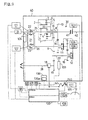
- HMT 40 is composed of an HST 21 and a mechanical speed change mechanism 30 having a differential part 7 as a planetary gear mechanism.
- HST 21 and mechanical speed change mechanism 30 are arranged forward and backward respectively so as to define positions of respective parts. These positions may be changed according to circumstances. For example, the before-and-behind relationship between HST 21 and mechanical speed change mechanism 30 may be reversed.
- HST 21 comprises an HST housing 31 joined to a center section 32.
- HST housing 31 are arranged in parallel a hydraulic pump 22 and a hydraulic motor 23, which are slidably rotatably attached to center section 32 so as to be fluidly connected with each other through a closed fluid circuit formed in center section 32.
- Center section 32 is fixed onto a front end of housing 33 for mechanical speed change mechanism 30.
- an input shaft (a speed change input part) 25 is disposed substantially horizontally between HST 21 and mechanical speed change mechanism 30.
- Input shaft 25 may be made of a single shaft.
- input shaft 25 consists of a front input shaft 25a and a rear input shaft 25b integrally joined coaxially with each other.
- Front shaft 25a penetrates HST housing 31 and center section 32.
- Rear shaft 25b is disposed in housing 33 so as to serve as a later-discussed first differential input part of differential part 7.
- Front shaft 25a serves as a later-discussed pump shaft of HST 21.
- a front end of front input shaft 25a projects forward from HST housing 31 toward a prime mover (in this embodiment, an engine) 24 so as to constitute an input part of HMT 40 (HST 21) receiving power of engine 24.
- a rear end of front input shaft 25a projects from center section 32 into housing 33 and is co-axially fixed to a front end of rear input shaft 25b with spline-fitting or the like.
- substantially vertical partition walls 34 and 35 are arranged before and behind.
- Rear shaft 25b penetrates partition wall 34 and is journalled by partition wall 35 through a bearing.
- HST 21 will be described.
- HST housing 31 are structured an axial piston type hydraulic pump 22 using input shaft 25 (front input shaft 25a) as a pump shaft.
- input shaft 25 penetrates a movable swash plate 22a.
- a cylinder block 22b is fittingly disposed around input shaft 25 so as not to be rotatable in relative to input shaft 25.
- a plurality of plungers 22c are slidably inserted into cylinder block 22b so that heads of plungers 22c abut against movable swash plate 22a.
- the slant angle of movable swash plate 22a is regulated so as to regulate the amount of hydraulic oil discharged from hydraulic pump 22.
- the hydraulic oil discharged from hydraulic pump 22 is sent to hydraulic motor 23 through an oil passage formed in center section 32.
- HST motor shaft 26 is journalled at its front and rear ends by HST housing 30 and partition wall 34 respectively through bearings.
- HST motor shaft 26 is also constituted by coaxial two front and rear shafts fixedly joined with each other.
- HST motor shaft 26 is also constituted by coaxial two front and rear shafts fixedly joined with each other.
- HST housing 31 In HST housing 31 are structured an axial piston type hydraulic motor 23 centering around HST motor shaft 26.
- HST motor shaft 26 penetrates a movable swash plate 23a.
- a cylinder block 23b is fittingly disposed around HST motor shaft 26 so as not to be rotatable in relative to HST motor shaft 26.
- a plurality of plungers 23c are slidably inserted into cylinder block 23b so that heads of plungers 23c abut against movable swash plate 23a.
- the slant angle of movable swash plate 23a is regulated so as to regulate the capacity of hydraulic pump 23, thereby regulating the rotational speed of hydraulic motor 23 in relative to the amount of oil discharged from hydraulic pump 22.
- a pump swash plate control device 121 and a motor swash plate control device 122 which are, for example, hydraulic servomechanisms, are provided as actuators for movable swash plate 22a of hydraulic pump 22 and movable swash plate 23a of hydraulic motor 23 respectively.
- Pump swash plate control device 121 and motor swash plate control device 122 are respectively incorporated in a pump control part 31a and a motor control part 31b of HST housing 31 as shown in Fig. 2.
- Control devices 121 and 122 are fittingly operated by a continuous shift of a speed ratio setting lever 120 serving as means for setting a speed ratio. They may be linked with lever 120 through a linkage.
- partition walls 34 and 35 are disposed in housing 33 as mentioned above so as to divide the interior space of housing 33 into a first chamber 33a, a second chamber 33b and a third chamber 33c arranged in this order from front to rear.
- a first speed change output shaft 27 and a second speed change output shaft 28 are disposed substantially in parallel to input shaft 25 (rear input shaft 25b) and HST motor shaft 26 so as to constitute speed change output parts. Ends or intermediate portions of shafts 27 and 28 are journalled by any of partition walls 34 and 35 and housing 33 through bearings.
- a positional relationship among rotary shafts 25, 26, 27 and 28 is such as shown in Fig. 2.
- a PT0 shaft 42 is rotatably supported in third chamber 33c and arranged coaxially to input shaft 25 so as to engage with and disengage from input shaft 25 through a hydraulic PT0 clutch 41.
- PT0 shaft 42 projects backward from the rear end of housing 33.
- an additional PT0 shaft may be provided in parallel to shaft 42 and interlock with shaft 42 through multi-speed gears or the like in third chamber 33c so as to be able to establish multi-speeds.
- engagement and disengagement of PT0 clutch 41 is controlled by an electromagnetic valve 107 whose output is controlled by controller 100.
- a PT0 switch 57 is provided on a vehicle and electrically connected to controller 100. By switching on PT0 switch 57, electromagnetic valve 107 is operated to engaging PT0 clutch 41.
- second speed change output shaft 28 projects forward from housing 33.
- HMT 40 of this embodiment is applicable to a vehicle like a crawler tractor, a combine or other vehicles having crawlers, which is provided at the front portion thereof with drive axles.
- a final driving mechanism like a transaxle apparatus (a differential gear unit interposed between the left and right drive axles) provided on a front portion of the vehicle, for example, a transmission shaft is interposed through universal joints.
- sub multi-speed gears and so on may be interposed between second speed change output shaft 28 and this final driving mechanism.
- HMT 40 is used for a vehicle like a wheel tractor which is provided at its rear portion with drive axles, such a modification may be allowed that second speed change output shaft 28 is extended backward so as to interlock with a differential gear unit (a final driving mechanism) for the rear drive axles which may be disposed in third chamber 33c, for example. Also in this case, sub multi-speed gears may be interposed between second speed change output shaft 28 and the final driving mechanism.
- a differential gear unit a final driving mechanism for the rear drive axles which may be disposed in third chamber 33c, for example.
- sub multi-speed gears may be interposed between second speed change output shaft 28 and the final driving mechanism.
- a gear 9 is fixed onto a portion of first speed change output shaft 27 close to the front end thereof. Gear 9 constantly engages with a gear 19 fixed on second speed change output shaft 28 so as to transmit the rotation of first speed change output shaft 27 to second speed change output shaft 28.
- the front end of second speed change output shaft 28 projects forward from housing 33, thereby, if the vehicle is a four-wheel vehicle, driving front wheels.
- a brake package in this embodiment, a multi-disc brake
- brake package 110 By pressing a brake pedal 140, brake package 110 is operated through a mechanical link 141 so as to brake second speed output shaft 28.
- brake switch 111 is switched on and its switch-on signal is inputted into controller 100.
- a gear 16 is relatively rotatably disposed on a portion of first speed change output shaft 27 close to the rear end thereof.
- a wet multi-plate type hydraulic clutch 12 is interposed between first speed change output shaft 27 and gear 16. By engaging hydraulic clutch 12, gear 16 is integrally joined with first speed change output shaft 27.
- a gear 15 is fixed onto a portion of HST motor shaft 26 close to the rear end thereof so as to constantly engage with gear 16. Thus, the rotation of HST motor shaft 26 is transmitted to first speed change output shaft 27 through gears 15 and 16 and clutch 12.
- a gear 14 is relatively rotatably provided on an intermediate portion of HST motor shaft 26.
- a wet multi-plate type hydraulic clutch 11 is interposed between HST motor shaft 26 and gear 14. By engaging hydraulic clutch 11, gear 14 is integrally joined with HST motor shaft 26.
- a gear 10 is fixed onto a transmission tube 8, which is relatively rotatably provided on input shaft 25 as discussed below, so as to constantly engage with gear 14 so that the rotation of HST motor shaft 26 is transmitted to transmission tube 8 through clutch 11 and gears 14 and 10.
- an electromagnetic valve 105 for switching clutch 11 and an electromagnetic valve 106 for switching clutch 12 are provided so that their outputs are controlled by controller (CPU) 100.
- controller (CPU) 100 controller (CPU) 100.
- valve 105 is switched off for disengaging clutch 11 and valve 106 is switched on for engaging clutch 12 so as to establish the HST mode.
- valve 105 is switched on for engaging clutch 11 and valve 106 is switched off for disengaging clutch 12 so as to establish the HMT mode.
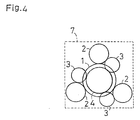
- differential part 7 as a planetary gear mechanism is disposed around input shaft 25. Differential 7 will be described in accordance with Figs. 1 and 3-9.
- a first sun gear 1 having outer peripheral teeth is fixed around input shaft 25 (rear input shaft 25b) so as to constitute a first differential input part.
- transmission tube 8 is relatively rotatably provided around input shaft 25 (rear input shaft 25b) so as to interlock with HST motor shaft 26 through gears 14 and 10, thereby constituting a second differential input part.
- First sun gear 1 and transmission tube 8 are rotatably supported by housing 33 and partition wall 34 respectively through bearings.
- a transmission tube 8 is integrally formed on its front end with an outer peripherally toothed second sun gear 4.
- Carrier 6 is relatively rotatably provided around transmission tube 8 and journalled by partition wall 34 through a bearing.
- Carrier 6 is pivotally provided thereon with a first planet gear 2 engaging with first sun gear 1, and provided with a second planet gear 3 engaging with second sun gear 4. Accordingly, first and second planet gears 2 and 3 revolve around coaxial first and second sun gears 1 and 4 respectively.
- first and second planet gears 2 and 3 tends to relatively revolve around the other.
- the relative position between both gears 2 and 3 cannot be changed.
- carrier 6 is actually rotated correspondingly to the relative revolution speed. Consequently, the greater difference of rotational speed there is between first and second sun gears 1 and 4, the faster carrier 6 rotates.
- second sun gear 4 rotates oppositely to first sun gear 1 (in this embodiment, when HST motor shaft 26 is rotated for backward traveling), the difference is further increased so as to make carrier 6 rotate faster in comparison with the case where second sun gear 4 is rotated in the same rotational direction of first sun gear 1 (in this embodiment, when HST motor shaft 26 is rotated for forward traveling).
- second sun gear 4 is an inner peripherally toothed ring gear.
- toothed second sun gear 4 is arranged so as to surround the outer revolution locus of second planet gear 3, thereby resulting in that differential part 7 is enlarged in the radial direction of input shaft 25.
- second sun gear 4 is outer peripherally toothed and disposed coaxially with first sun gear 1 so as to minimize differential part 7 in its radial direction.
- First sun gear 1 is attempted to receive the rotational force of an HST pump shaft so as to constitute the first differential input part.
- first sun gear 1 is directly fixed onto rear input shaft 25b coaxially and integrally connected to front input shaft 25a serving as the pump shaft of HST 21.
- differential part 7 becomes coaxial with hydraulic pump 22 of HST 21, thereby enabling HMT 40 to be further minimized so as to be advantageously applicable to vehicles, industrial machineries such as agricultural machineries or construction machineries, and so on.
- Partition wall 34 is longitudinally bored therethrough with bearing holes 34a, 34b, 34c, 34d and so on. Bearings are fitted into the respective bearing holes, and the rotary shafts penetrate the respective bearings. In this regard, bearings are fitted into bearing holes 34b, 34c and 34d for rotatably supporting HST motor shaft 26, first speed change output shaft 27 and second speed change output shaft 28 respectively.
- the inner peripheral surface of bearing hole 34a is longitudinally sectioned into front and rear parts. Bearings for carrier 6 and transmission tube 8 are fitted into the front and rear parts of bearing hole 34a respectively.
- partition wall 34 is stepped in front of bearing hole 34a with first recess 34e and second recess 34f.
- First recess 34e accommodates the diametrically largest rear end portion of carrier 6.
- Second recess 34f behind first recess 34e accommodates a gear 5 fixed around the diametrically smallest portion of carrier 6.
- a lower portion of second recess 34f is partly notched toward a space just behind bearing hole 34c.
- a gear 9 is arranged just behind bearing hole 34c so as to engage with gear 5 in second recess 34f.
- first and second chambers 33a and 33b communicate with each other through the engaging portion between gears 5 and 9.
- partition wall 34 generally separates first chamber 33a accommodating differential part 7 from second chamber 33b accommodating hydraulic clutches 11 and 12 so as to prevent sludge generated from hydraulic clutches 11 and 12 from influencing differential part 7, thereby securing the endurance of differential part 7.
- HMT mode a first transmission mode
- HMT mode a second transmission mode
- HST mode only the driving effort of hydraulic motor 23 of HST 21 (the rotational effort of HST motor shaft 26) is transmitted to first speed change output shaft 27.
- HMT mode the rotational effort of carrier 6 of differential part 7 differentially connecting input shaft 25 as the input shaft of HST 21 with HST motor shaft 26 is transmitted to first speed change output shaft 27.
- the setting of a speed ratio depends upon the detection of voltage of position sensor 120a varied by shifting speed ratio setting lever 120.
- the rotational speed of input shaft 25 (hereinafter, referred to as "input rotational speed" of HMT 40) is detected by an input side rotational speed detector 104 arranged adjacent to input shaft 25, and the rotational direction and speed of first speed change output shaft 27 (hereinafter, this rotational speed is referred to as “output rotational speed” of HMT 40) is detected by an output side rotational speed detector 103 arranged adjacent to first speed change output shaft 27 (gear 9 thereon).
- the detection signals of both detectors 103 and 104 is input into controller 100 so as to calculate a ratio of the detection value of output side rotational speed detector 103 to that of input side rotational speed detector 104, i.e., a ratio of the output rotational speed to the input rotational speed, referred to as the speed ratio.
- controller 100 computes an actual speed ratio from the detection of both rotational speed detectors 103 and 104. Then, at least one of pump swash plate control device 121 and motor swash plate control device 122 serving as output means is operated so as to make the actual speed ratio agree with the target speed ratio. Additionally, electromagnetic valves 105 and 106 are exchanged with each other in their opening and closing at the period for changing the transmission mode.
- a speed ratio indicator 108 is electrically connected to controller 100 in addition to as above-mentioned electromagnetic valves 105, 106 and 107.
- Speed ratio indicator 108 may indicate the target speed ratio on the basis of the detection signal of position sensor 102a. Alternatively, it may indicate the actual speed ratio on the basis of the computation of speed ratio by using both rotational speed detectors 103 and 104.
- an oil temperature sensor 131 for detecting the temperature of hydraulic oil is provided on a hydraulic oil tank 130.
- the temperature detected by temperature sensor 131 is used for amending the period for changing the transmission mode as discussed below referring to Fig. 15.
- an engine rotation controller 58 as an electric governor is electrically connected to controller 100.
- a vehicle is provided thereon with an accelerator like a lever or a pedal serving as a rotational speed setting means, a position (an angle) of which is detected by an accelerator sensor 59 electrically connected to controller 100.
- accelerator sensor 59 On the basis of the detection value of accelerator sensor 59, engine rotation controller 58 adjusts an actual engine rotational speed so as to make it agree with the rotational speed set by the accelerator.
- this engine rotation controller 58 can be set into a load control mode, wherein the engine rotational speed set by the accelerator can be amended on the basis of detection of load on an engine in correspondence to excessive load or light load. The speed ratio control corresponding to the variance of engine rotational speed in the load control mode will be discussed later in accordance with Figs. 24 and 25.
- speed ratio V is optionally and continuously set by speed ratio setting lever 120 from a rearward traveling middle speed range RM to a forward traveling high speed range FH through a rearward traveling low speed range EL, a stationary (neutral) position N, a forward traveling low speed range FL and a forward traveling middle speed range FM.
- this graph of speed ratio V can be replaced with the output rotational speed (the rotational speed of first speed change output shaft 27).
- the values during rotation for forward traveling are positive, and those during rotation for rearward traveling are negative.
- the HST mode is selected so that the vehicle drives only with the rotational force of hydraulic motor 23 of HST 21.
- speed ratio V is set between forward traveling middle speed range FM and forward traveling high speed range FH
- the HMT mode is selected so that first speed change output shaft 27 is accelerated by the rotation of carrier 6.
- speed ratio setting lever 120 when speed ratio setting lever 120 is located at a speed ratio setting position for change of the transmission mode (hereinafter, such a position is referred to as a "mode change position") X serving as a boundary between forward traveling low speed range FL and forward traveling middle speed range FM or its vicinity, and then, the computed actual speed ratio reaches a speed ratio corresponding to the change of transmission mode (hereinafter, such a speed ratio is referred to as a "mode change speed ratio”) Vx, electromagnetic valves 105 and 106 are exchanged with each other in their opening and closing so as to change the transmission mode.
- mode change position a speed ratio setting position for change of the transmission mode
- Vx electromagnetic valves 105 and 106 are exchanged with each other in their opening and closing so as to change the transmission mode.
- mode change position X defining the boundary between forward traveling low speed range FL and forward traveling middle speed range FM must be set so that the rotational speed of first speed change output shaft 27 is not suddenly varied by change of transmission mode.
- carrier 6 runs idle following the rotation of first speed change output shaft 27.
- mode change position X is preferably set at the speed ratio setting position which agrees with the driving speed of carrier 6 caused by the difference of rotational speed between first sun gear 1 rotating integrally with input shaft 25 (i.e., the pump shaft of hydraulic pump 22) and second sun gear 4 following HST motor shaft 26 (i.e., the motor shaft of hydraulic motor 23) during the HMT mode.
- speed ratio setting lever 120 While speed ratio setting lever 120 is shifted from a maximum backward traveling speed ratio setting position Rmax to a maximum forward traveling speed ratio setting position Fmax through neutral position N, either pump swash plate control device 121 or motor swash plate control device 122 is operated on the basis of detection by position sensor 120a so as to optionally change the position of either movable swash plate 22a of hydraulic pump 22 or movable swash plate 23a of hydraulic motor 23.
- a pump discharge amount Dp as an amount of oil discharged from hydraulic pump 22 during the forward traveling is a positive value varying in proportion to a slant angle of movable swash plate 22a from the neutral position (hereinafter, simply named as a "slant angle") in its forward traveling rotation range
- pump discharge amount Dp during the rearward traveling is a negative value in proportion to the slant angle in the rearward traveling rotation range of swash plate 22a.
- a relative discharge amount of hydraulic pump 22 to hydraulic motor 23 (hereinafter, simply named as a "relative discharge amount”) becomes the maximum which is the maximum of pump discharge amount Dp from which minimum motor discharge amount Dm1 (Dm1>0) is subtracted, thereby rotating HST motor shaft 26 at the maximum speed in the reverse direction (for the rearward traveling of the vehicle).
- the slant angle of movable swash plate 23a is increased, i.e., motor discharge amount Dm is increased while movable swash plate 22a is kept slant at the maximum angle for rearward traveling, thereby reducing the relative discharge amount.
- the shift point where slantingly rotated swash plate 23a reaches its maximum slant angle so as to set motor discharge amount Dm to maximum amount Dm2 is defined as a boundary point Y between rearward traveling middle speed range RM and rearward traveling low speed range RL.
- movable swash plate 22a is slantingly rotated from the maximum slant angle for rearward traveling to its neutral position so as to reduce its slant angle while movable swash plate 23a is held so that motor discharge amount Dm is kept maximum amount Dm2.
- pump discharge amount Dp in the backward traveling is reduced so as to decelerate the reverse rotation of HST motor shaft 26.
- the transmission mode is the HST mode so that the rotation of HST motor shaft 26 is transmitted to first speed change output shaft 27 (and second speed change output shaft 28) without passing differential part 7.
- the rotational speed of first speed change output shaft 27 is proportional to that of HST motor shaft 26.
- the rotational direction of first speed change output shaft 27 is changed by changing the rotational direction of HST motor shaft 26.
- the rotation of carrier 6 of differential part 7 is transmitted to first speed change output shaft 27.
- pump discharge amount Dp is decreased so as to decelerate the rotation of HST motor shaft 26 in the normal direction while motor discharge amount Dm is kept to be maximum amount Dm1.
- HST motor shaft 26 becomes stationary, and then, rotates its reverse direction so as to increase the rotational speed.
- the difference of rotational speed between first sun gear 1 and second sun gear 4 is increased so as to accelerate the rotation of carrier 6.
- the shift position where pump discharge amount Dp reaches a maximum amount -Dpi for rearward traveling i.e., movable swash plate 22a is slantingly rotated to the maximum slant angle in its rearward traveling rotation range
- pump discharge amount -Dp1 is kept and movable swash plate 23a is slantingly rotated so as to reduce its slant angle, whereby motor discharge amount Dm is increased.
- HMT 40 controlled in this manner is provided on a working vehicle such as an agricultural tractor, which is usually intended to travel at work between its rearward traveling range and forward traveling low speed range.
- a working vehicle such as an agricultural tractor
- the vehicle is driven in the HST mode wherein the rotation of HST motor shaft 26 with high torque is substantially directly transmitted to first speed change output shaft 27 through gears 15 and 16 and hydraulic clutch 12.
- the traveling speed of the vehicle can be minutely continuously changed so as to secure a work of high quality.
- the vehicle is driven in the HMT mode when its traveling speed is set between a forward traveling middle speed range and a forward traveling high speed range. At this time, of course, the traveling speed can be continuously changed. Furthermore, the loss of engine output can be restricted so as to reduce fuel expenses. This is greatly advantageous in a case where a small size vehicle having a low-torque engine is attempted to travel at high speed.
- the mechanical speed change device must be provided with many drive trains like gears for establishing sufficiently many speed stages in wide from low to high so that the mechanism thereof is complicated and entirely enlarged.
- the traveling speed must be changed step by step.
- the HMT according to the present invention can continuously change its output speed in the whole traveling speed range to be set.
- differential part 7 is structured as one unit so as to simplify and minimize the entire structure of the HMT, thereby easing its assembly and reducing the manufacturing costs.
- multi-speed change mechanism such as a gear type may be disposed at the transmission downstream of first speed change output shaft 27, when required.
- HMT 40' shown in Fig. 12 is a modification of HMT 40.
- a drive train from input shaft 25 to first speed change output shaft 27 without either passing HST 21 or differential part 7 is additionally provided.
- a gear 36 is fixed onto input shaft 25.
- a gear 37 is relatively rotatably provided around first speed change output shaft 27 so as to constantly engage with gear 36.
- a hydraulic clutch 13 is provided around first speed change output shaft 27 so as to be interposed between gear 37 and first speed change output shaft 27.
- Hydraulic clutch 13 is engaged and disengaged by an electromagnetic valve 109 controlled by controller 100.
- first speed change output shaft 27 can be rotated fast without loss of power in transmission.
- a transmission mode is referred to as a mechanical drive mode.
- Fig. 13 is a table describing clutches 11, 12 and 13 in respective transmission modes of HMT 40'.
- the transmission mode is switched into the mechanical drive mode when the maximum speed ratio is set in forward traveling high speed range FH.
- engaged clutch 11 is disengaged
- clutch 12 is kept to be disengaged
- disengaged clutch 13 is engaged.
- the mode change period from the HMT mode to the mechanical drive mode is attempted to be a time when the output rotational speed (of first speed change output shaft 27) established by the rotation of carrier 6 of differential part 7 through gears 5 and 9 substantially coincides with that established by the transmission from input shaft 25 through gears 36 and 37. Therefore, when the transmission mode is changed from the HMT mode to the mechanical drive mode, sudden speed difference is not generated so as to secure a smooth speed change.
- speed ratio V that can prevent the difference of speed during the mode change between the HMT mode and the mechanical drive mode is provided as this speed ratio corresponding to the transmission mode change.
- the speed change can be performed only by variance of engine rotational speed, i.e., setting of the accelerator. Therefore, it is appropriate that the speed ratio setting position corresponding to the mode change from the HMT mode to the mechanical drive mode agrees with maximum forward traveling speed ratio position Fmax of speed ratio setting lever 120.
- Fig. 14 shows a torque plot 61 and an output power plot 62 in relation to a rotational speed ER of an engine 24 of a certain type. This engine is lacking in both torque and output power until its rotational speed ER reaches a certain rotational speed ER1.
- a torque Tr becomes stable, and output power P is increased according to the increase of engine rotational speed ER.
- output power P is reduced, and torque Tr suddenly falls down.
- engine rotational speed ER is detected by rotational speed detector 103 and the like. If engine rotational speed ER is off the range between rotational speeds ER1 and ER2 and its vicinity, the transmission mode is not changed into the mechanical drive mode.
- speed ratio setting lever 120 is shifted so as to change the position of movable swash plate 22a or 23a and the transmission mode is changed between the HST mode and the HMT mode so that the output speed of HMT 40 is sequentially changed in the whole speed ratio range set by speed ratio setting lever 120. Furthermore, it will be attempted that the change period of transmission mode is amended, the ratios of acceleration and deceleration are amended, and so on, thereby improving HMT 40 in its speed change feeling.
- this embodiment employs the structure that the change of transmission mode depends upon computation of speed ratio V on the basis of detection by input side rotational speed detector 104 and output side rotational speed detector 103.
- the transmission mode is changed at the period when the output rotational speed (of first speed change output shaft 27) according to the HST mode coincides with the output rotational speed according to the HMT mode, i.e., if referring to Fig. 6, when shifted speed ratio setting lever 120 reaches mode change position X so that pump discharge amount Dp becomes amount Dp2 and that actual speed ratio V becomes mode change speed ratio Vx.
- this change of transmission mode there are generated an electric lag between computation by controller 100 and transmission of output signals to electromagnetic valves 105 and 106, and a mechanical lag for actual operation of electromagnetic valves 105 and 106 so as to engage and disengage hydraulic clutches 11 and 12. Accordingly, when the transmission mode is actually changed, the rotational speed according to the HST mode becomes considerably different from that according to the HMT mode so as to generate sudden speed variance attended with shock.
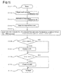
- controller 100 stores a map of electric and mechanical turnaround time of clutches 11 and 12 corresponding to the hydraulic oil temperature and the engine rotational speed. The values detected as mentioned above are applied into this map so as to calculate a lag d (at a process 204).
- a computer simulation is performed so as to calculate how much value an actual speed ratio V(t) at an optional speed ratio setting period t becomes after a time d (seconds), i.e., an estimated speed ratio V(t+d).
- the simulation is performed by the Milne principle.
- various simulation manners may be employed under counting lags d.
- estimated speed ratio V(t+d) computed during acceleration is compared with mode change speed ratio Vx. If speed ratio V(t+d) is not less than mode change speed ratio Vx (i.e., V(t+d) ⁇ Vx), speed ratio V corresponding to the transmission mode change is reached before d seconds takes since period t. At this time, a process 207 for engaging clutch 11 is performed. Thus, gear 14 is driven by HST motor shaft 26 so as to begin to transmit the rotation of HST motor shaft 26 to second sun gear 4 of differential part 7.
- process 207 is not performed so that clutch 11 remains being disengaged so as not to establish that only clutch 12 is disengaged, because V(t) is necessarily less than Vx.
- Fig. 16 shows a computation of estimated speed ratio V(t+d) at optional period t during acceleration. While speed ratio setting lever 120 is shifted for acceleration, the voltage of position sensor 120a is detected time after time. At every optional detection period t, eliminated speed ratio V(t+d), which is reached by speed ratio V(t) after time lag d (seconds), is computed. The timing when speed ratio V(t) reaches mode change speed ratio Vx is referred to as a mode change timing Tx. At a period t1 from which it takes a longer time than time d (seconds) before mode change timing Tx, computed eliminated speed ratio V(t1+d) does not reach mode change speed ratio Vx. Therefore, clutch 11 is still disengaged (i.e., electromagnetic valve 105 remains off) and clutch 12 is still engaged (i.e., electromagnetic valve 106 remains on) so as to keep the HST mode.
- clutch 11 is still disengaged (i.e., electromagnetic valve 105 remains off) and clutch 12 is still engaged (i
- Fig. 16 shows the above-mentioned timing for switching respective clutches 11 and 12 during the mode change from the HST mode to the HMT mode in correspondence to the speed ratio setting period.
- clutches 11 and 12 remain off and on respectively, thereby keeping the HST mode.
- eliminated speed ratio V(t2+d) becomes mode change speed ratio Vx.
- electromagnetic valve 105 for clutch 11 is switched on.
- clutch 11 is perfectly engaged. In other words, before mode change period Tx, the output signal for actuation is transmitted to clutch 11 and clutch 11 approximately completes its actuation.
- clutch 12 begins its actuation for disengagement almost since mode change period Tx.
- mode change period Tx time d ahead of mode change period Tx, at first, clutch 11 begins its actuation for engagement (if during deceleration, for disengagement). Then, since mode change period Tx, clutch 12 begins its actuation for disengagement (if during deceleration, for engagement). Consequently, speed ratio V becomes almost mode change speed ratio Vx while clutches 11 and 12 actuate (after clutch 11 completes its actuation) so that a difference of the output rotational speed is not generated between the pre-change of transmission mode and the post-change thereof, thereby preventing sudden variance of traveling speed of the vehicle.
- speed ratio setting lever 120 is located at a position where mode change speed ratio Vx is obtained, and then, the vehicle travels under intensive variance of load, e.g., tractive load, the actual speed ratio (i.e., the ratio of the value detected by output side rotational speed detector 103 to the value detected by input side rotational speed detector 104) varies even when the load varies slightly, so that the change of transmission mode is automatically performed frequently, thereby increasingly stressing clutches 11 and 12 and the like, and continuously generating frequent vibration.
- intensive variance of load e.g., tractive load
- the transmittion mode is not changed, i.e., the current transmittion mode is kept, unless the position of speed ratio setting lever 120, i.e., the voltage from position sensor 120a changes. Due to this control, the vehicle like a tractor in traction, which travels under frequently varying load, can be stabilized in its travel without frequently automatic change of transmission mode.
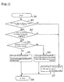
- controller 100 judges whether brake switch 111 is on or off (i.e., whether brake pedal 140 is pressed or not). If brake switch 111 is on (brake pedal 140 is pressed), either clutch 11 or 12 which has been engaged is disengaged. In detail, when the transmission mode is the HST mode, engaged clutch 12 is disengaged. When the transmission mode is the HMT mode, engaged clutch 11 is disengaged. Consequently, both clutches 11 and 12 are disengaged. (Incidentally, if HMT 40' is used and the transmission mode is the mechanical drive mode, clutch 13 is disengaged.)
- first speed change output shaft 27 and second speed change output shaft 28, which is braked by brake 18 while engaging with first speed change output shaft 27 through gears, are shut off from the power transmitted from either HST motor shaft 26 or carrier 6 of differential part 7 (from input shaft 25 toward braked second speed change output shaft 28 in the mechanical drive mode of HMT 40') so that the driving force does not conflict the braking operation. Consequently, the braking effect is excellently generated and clutches 11 and 12 (and 13) can be prevented from being wasted, thereby being improved in its endurance.
- conditional branch 212 when an on-signal from brake switch 111 is not detected, the process is advanced to a conditional branch 212, wherein the result of preceding detection of brake switch 111 (preceding conditional branch 212) is judged. If the on-signal of brake switch 111 is not detected at the last time, it is decided that brake pedal 140 remains unpressed, whereby a final process is reached so as to break the running loop, and continuously, the next loop starts from a starting process.
- conditional branch 212 If an on-signal of brake switch 111 is detected at preceding conditional branch 212, i.e., if the on-signal of brake switch 111 is not detected in the running loop but detected in the preceding loop, this condition means that pressed brake pedal 140 is released. Then, at a process 215, the actual speed ratio is detected and adjusted to agree with the target speed ratio. Further, at a process 216, the slant angles of hydraulic pump 22 and motor 23 are analyzed from this target speed ratio. Controller 100 controls the slant angles of hydraulic pump 22 and motor 23 through pump-and-motor swash plate control devices 121 and 122. Then, at conditional branch 217, the target speed ratio is compared with mode change speed ratio Vx.
- a process 218 for engaging clutch 11 is performed so as to establish the HMT mode. If the target speed ratio is less than mode change speed ratio Vx, a process 219 for engaging clutch 12 is performed so as to establish the HST mode.
- both pump swash plate control device 121 and motor swash plate control device 122 are controlled so as to operate both swash plates 22a and 23a simultaneously.
- position sensor 120a detects position B as a target speed ratio position. Controller decides that lever 120 is shifted between two speed ranges of forward traveling high speed range FH and forward traveling middle speed range FM. Then, motor swash plate control device 122 is operated to rotate movable swash plate 23a so that motor discharge amount Dm becomes maximum amount Dm2. Simultaneously, pump swash plate control device 121 is also operated to rotate movable swash plate 22a to an angle corresponding to position B.
- speed ratio setting lever 120 may be shifted across mode change position X, e.g., it may be shifted from a position C in forward traveling low speed range FL to position A in forward traveling high speed range FH.
- position A detected by position sensor 120a is decided as the target speed ratio position, the change of transmission mode is performed in addition to the simultaneous operation of both movable swash plates 22a and 23a, whereby component parts such as clutches 11 and 12 are greatly shocked.
- mode change speed ratio Vx is input as a provisional target speed ratio position into controller 100 so as to change the transmission mode.
- target speed ratio position A is input so as to operate movable swash plates 22a and 23a simultaneously, thereby establishing the speed ratio corresponding to position A.
- the simultaneous operation of movable swash plates 22a and 23a is performed after the change of transmission mode, thereby enabling a speed change without a shock.
- a speed ratio setting position (a target speed ratio position), at which shifted speed ratio setting lever 120 arrives, is detected so that controller 100 decides whether te shift is performed across mode change position X or not. If mode change position X is not crossed, the change of transmission mode is unnecessary. Therefore, at a process 224, regarding the detected speed ratio as the target speed ratio, movable swash plates 22a and 23a of hydraulic pump 22 and motor 23 are simultaneously operated for speed change.
- controller 100 decides that the shift is performed across transmission mode change position X, a process 223 is performed so that controller 100 determines mode change speed ratio Vx as a provisional target speed ratio. Then, at a conditional branch 225, controller 100 judges whether the current timing comes to be correspondent to the change of transmission mode, i.e., whether the actual speed ratio (which is detected by both rotational speed detectors 103 and 104) becomes mode change speed ratio Vx or not (including the case where the above-mentioned amendment of timing). If the change of transmission mode is decided to be impossible (i.e., if it is a timing when the change of transmission mode generates a difference of the rotational speed), a waiting loop 226 repeats.
- a process 227 is performed so as to change the transmission mode.
- a process 228 is performed so that the speed ratio pointed by shifted speed ratio setting lever 120 is set as the target speed ratio and hydraulic pump 22 and motor 23 are simultaneously operated, thereby establishing sudden acceleration or deceleration.
- the degree of acceleration and deceleration is increased in correspondence to the shift of speed ratio setting lever 120 over a plurality of speed ranges.
- the target speed ratio is set in correspondence to the stroke of speed ratio setting lever 120 for improvement of operational feeling (i.e., for obtaining desirable traveling speed or acceleration or deceleration).
- a graph of target speed ratio V in this embodiment, during forward traveling in relation to an input voltage S from position sensor 120a for detecting a position of speed ratio setting lever 120 is memorized for obtaining a good operational feeling.
- a variance ratio of target speed ratio V i. e. , a variance ratio ⁇ V
- a variance ratio ⁇ V is not held constant but it is held down in a (forward traveling) low speed range and raised in a (forward traveling) high speed range, while it is set in-between in a (forward traveling) middle speed range.
- target speed ratio V is increased in the whole speed range from the stationary position to the maximum speed ratio position while an increase ratio ⁇ V1 (i.e., the increasing or decreasing degree of speed ratio V every unit of stroke s of speed ratio setting lever 120 or every voltage variance of position sensor 120a) corresponding to the low speed range is constantly held, speed ratio setting lever 120 must be shifted in an extremely long stroke.
- an increase ratio ⁇ V3 is fixed, and then, the vehicle travels at a low speed for a ground work or the like, even a slight stroke generates a great variance of speed ratio, thereby preventing a delicate speed regulation.
- the variance ratio of target speed ratio to the stroke is made befitting each of the speed ranges so as to improve the operational feeling of speed ratio setting lever 120. Consequently, the difference generated between the operation by an operator and an actually obtained speed can be restricted.
- the low speed range is often set when the vehicle travels at work like a ground work, or when the vehicle is going to be housed. Then, if the variance ratio of speed ratio to the stroke of speed ratio setting lever 120 (i.e., to the variance of input voltage s from position sensor 120a) is too large, the traveling speed varies beyond expectation, thereby resulting in a rough work. Therefore, variance ratio ⁇ V1 of target speed ratio in this speed range is held down.
- variance ratio ⁇ V2 of target speed ratio in this speed range is set to be larger than variance ratio ⁇ V1 for the low speed range.
- the high speed range is set when the vehicle normally travels on a road. In this condition, greatly large acceleration and deceleration in relative to the stroke of speed ratio setting lever 120 is desired. Therefore, variance ratio ⁇ V3 of target speed ratio is set to be further large.
- the low, middle and high speed ranges set as shown in Fig. 19 are not concerned with forward traveling low speed range FL, forward traveling middle speed range FM and forward traveling high speed range FH which correspond to the above-mentioned control (shown in Fig. 10) of hydraulic pump 22 and motor 23 and the change of transmission mode.
- the degree of variance of output value for controlling pump swash plate control device 121 in relation to the stroke of speed ratio setting lever 120 is changed every speed range.
- the output value is held down in the low speed range. It is rather large in the middle speed range, and further raised in the high speed range.
- This control can be also applicable to a continuously variable transmission which is not an HMT but has only an HST.
- the discharge amount between hydraulic pump and motor in the HST i.e. , a movable swash plate for changing this discharge amount
- the degree of angle of the swash plate swash plate in variance can be set variously, thereby enabling the increase and decrease ratio of speed ratio to be varied.
- the variance ratio of speed ratio is constant in each of the low, middle and high speed ranges.
- any other manner than such a classification may be employed. All to be required is that the speed ratio is set so as to befitting each optional speed ratio position pointed by speed ratio setting lever 120. The change of variance ratio of speed ratio is only a result of this speed ratio setting.
- the relationship between the position of speed ratio setting lever 120 and the target speed ratio as shown in Fig. 19 may be obtained.
- pump discharge amount P is changed (i.e., movable swash plate 22a is operated) under the HST mode, thereby enabling small variance ratio ⁇ V1 of target speed ratio to be obtained.
- pump discharge amount P is changed (i.e., movable swash plate 23a is operated) under the HMT mode, thereby enabling rather large variance ratio ⁇ V2 to be obtained.
- motor discharge amount M is changed under the HMT mode, thereby enabling extremely large variance ratio ⁇ V3 to be obtained.
- a shift speed (operation speed) of speed ratio setting lever 120 is computed and the target speed ratio is amended in correspondence to the operation speed so that a target speed ratio larger than an actual speed ratio is set as a provisional target speed ratio. Accordingly, variance ratio of speed in acceleration and deceleration can be increased by shifting lever 120 faster.
- This control as well as the foregoing control is applicable to a structure such that the pointed value of speed ratio is electrically detected and a movable swash plate of an HST for changing a speed ratio is variously changed in its rotational speed. Also, this is applicable to a continuously variable transmission having only an HST as well as HMT 40.
- a speed ratio corresponding to the actual position of speed ratio (input voltage s from position sensor 120a) every moment is input as a target speed ratio V into controller 100.
- target speed ratio V is continuously input.
- the final position reached by lever 120 is a final target speed ratio. Accordingly, even if speed ratio setting lever 120 is shifted fast, the increase of speed ratio falls short of expectation unless shifted lever 120 reaches a certain position.
- controller 100 is provided with a target speed amendment circuit 100a as shown in Fig. 20.
- This circuit 100a reads a variance of input voltage s from position sensor 120a of speed ratio setting lever 120 and calculate the degree thereof every unit time, i.e. , a variance speed of target sped ratio (i.e., ⁇ V/ ⁇ t). This is multiplied by a coefficient k (k* ⁇ V/ ⁇ t) to serve as amended target speed ratio V.
- This amended value is increased as the variance speed of target speed ratio V is increased, i.e., as the shift of speed ratio setting lever 120 is faster.
- controller 100 outputs to the actuators for controlling a speed ratio (i.e., pump-and-motor swash plate control devices 121 and 122 or electromagnetic valves 105 and 106). Consequently, when a speed ratio which is larger than the present value set by speed ratio setting lever 120 is desired, and even if the target speed ratio setting position is far from the existing position of speed ratio setting lever 120, lever 120 is shifted a little but fast so as to set a larger provisional target speed ratio, thereby enabling an actual speed ratio to approach the provisional target speed ratio before lever 120 reaches the target position. Consequently, the actual speed ratio can early reach the final target speed ratio.
- a speed ratio i.e., pump-and-motor swash plate control devices 121 and 122 or electromagnetic valves 105 and 106.
- this control system is employed by an HMT, such a control of acceleration and deceleration over different speed ranges as shown in Fig. 18 may be also adopted.
- the shift speed is so increased as to enable the provisional target speed ratio to be set in forward traveling high speed ratio so that both movable swash plates 22a and 23a of hydraulic pump 22 and motor 23 are operated simultaneously, thereby increasing the variance ratio in acceleration and deceleration.
- HST 21 Since HST 21 is varied in its volumetric efficiency by variance of load, it happens that the traveling speed of the vehicle falls short of expectation in however stroke speed ratio setting lever 120 is operated so as to control hydraulic pump 22 and motor 23. Therefore, in the case where the set speed ratio corresponding to the position of speed ratio setting lever 120 is considerably different from the actual speed ratio, the pump-or-motor discharge amount is adjusted so as to coincide the actual speed ratio with the set speed ratio.
- this control flow starts (from the starting process 231) in the case where the actual speed ratio computed basing on the detection of rotational speed detectors 103 and 104 is different from the set speed ratio detected by position sensor 120a.
- a conditional branch 232 it is judged whether the slanting angle of movable swash plate 22a of hydraulic pump 22 is the maximum. If movable swash plate 22a is out of the maximum slanting angle, pump swash plate control device 121 is commanded to adjust pump discharge amount Dp with tilting movable swash plate 22a, thereby amending the speed ratio.
- a process 233 is performed so as to compute a target slanting angle of movable swash plate 23a of hydraulic motor 23 and command motor swash plate control device 122 to tilt movable swash plate 23a for adjusting motor discharge amount Dm, thereby amending the speed ratio.
- Controller 100 when detecting that the voltage issued from position sensor 120a corresponds to stationary position N, judges whether movable swash plate 22a of hydraulic pump 22 of HST 21 is adjacent to its neutral position or not (i.e., the slanting angle thereof is approximately a degree of zero) at a conditional branch 242.
- a process 247 is performed so that pump swash plate control device 121 is operated to bring movable swash plate 22a to the neutral position (adjust its slant angle to 0 degree).
- the running loop is broken at an end 248 and the next loop starts from a start 241.
- conditional branch 242 if speed ratio setting lever 120 is detected to be adjacent to the stationary position, a process is advanced to a conditional branch 243 wherein it is judged whether the speed ratio corresponds to low-speed-traveling (i.e., V ⁇ V L ? hereinafter, the speed ratio in this range is referred to as an "extremely low speed ratio"). If the extremely low speed ratio (V ⁇ V L ), the direction of first speed change output shaft 27 in rotation is ascertained by output side rotational speed detector 103 at a conditional branch 244.
- movable swash plate 22a is tilted toward its rearward traveling range side at the minimum variable angle (the minimum adjustable unit of slant angle of movable swash plate 22a by pump swash plate control device 121).
- a process 245 is performed so that pump swash plate control device 121 is operated to tilt movable swash plate 22a toward its forward traveling range side at the minimum variable angle.
- the direction of the movable swash plate toward the maximum angle for forward traveling is positive, and its opposite direction is negative.
- the running loop passing either process 245 or 246 is broken at end 248 and the next loop starts from start 241 so that the above-mentioned flow is repeated.
- the vehicle traveling forwardly at an extremely low speed is decelerated and stops according to process 246 wherein hydraulic motor 23 is slightly driven for rearward traveling, and then, the vehicle tends to travel rearwardly at an extremely low speed.
- hydraulic motor 23 is slightly driven for forward traveling at this time.
- the vehicle is decelerated again and stops, and then tends to travel forwardly. Due to this repetition of loop, movable swash plate 22a repeats its small reciprocal movements between its forward-and-rearward traveling range sides at the minimum movable angle, thereby keeping the vehicle itself stationary.
- the stationary vehicle can be held even on a slope because power is transmitted into first speed change output shaft 27. If speed ratio setting lever 120 is operated again to an optional speed ratio setting position for either forward or rearward traveling, clutching and other operations are not required, thereby diminishing a delay in starting of the vehicle so as to improve the operational feeling.
- PT0 switch 57 for switching on-and-off electromagnetic valve 107 as an actuator for a PTO clutch 41 is connected to controller 100.
- a load control mode switch 56, an engine rotation controller (an electric governor) 58 and an accelerator sensor 59 as means for determining an engine rotational speed are connected to controller 100.
- the output rotational-speed of engine 24 is controlled by engine rotation controller (electric governor ) 58, normally, so as to agree with the set rotational speed thereof detected by accelerator sensor 59.
- engine rotation controller electric governor
- load control mode switch 56 when load control mode switch 56 is switched on, it is set into the load control mode, wherein load applied on engine 24 (an engine load ratio L which becomes 100 % when the output of engine 24 reaches the maximum endurable value) is detected and entered into controller 100, and controller 100 issues a command signal to engine rotation controller 58 if necessary on deciding from average engine load ratio L, thereby increasing or decreasing engine rotational speed ER.
- the traveling speed is determined as engine rotational speed ER multiplied by speed ratio V.
- speed ratio V established by a transmission is held constant, the variation of engine rotational speed ER results in the variation of traveling speed. If speed ratio V in the transmission is increased and decreased in correspondence to the increase and decrease of engine rotational speed ER, the traveling speed can be held. However, such a control is difficult in a mechanical transmission.
- speed ratio V can be easily changed by tilting movable swash plate 22a of hydraulic pump 22 or movable swash plate 23a of hydraulic motor 23. Then, the control of speed ratio in HMT 40 is combined with the control of engine rotational speed according to the load control mode in engine rotation controller 58 so that the traveling speed can be held while the engine rotational speed is varied.
- movable swash plate 22a or 23a is controlled so that HST motor shaft 26 is, when the HST mode, accelerated, and when the HST mode, decelerated (if it is rotated for rearward traveling, accelerated), thereby holding the output rotational speed of HMT 40, i.e. , the rotational speed of first speed output shaft 27 so as to hold the traveling speed.
- speed ratio V is reduces as much, thereby holding the traveling speed.
- a continuously variable transmission having an HST, as well as an HMT can be controlled so as to change the speed ratio in correspondence to the variance of engine rotational speed in this manner.
- This control requires that the speed ratio set by speed ratio setting lever 120 is within a range for permission of main work (e. g., a speed ratio range wherein the traveling speed is less than 10 km/h while the engine is rotated at a rated speed.
- the maximum speed ratio of such a speed ratio range is hereinafter referred to as "Vw”.).
- Vw The maximum speed ratio of such a speed ratio range.
- the degree of speed ratio adjusted in correspondence to the variance of engine rotational speed basing on the detection of load is different from that in the low speed range (i.e., variance ratio ⁇ V of speed ratio is different between the two speed ratio ranges) so as to complicate the control, if the traveling speed is going to be still held.
- the frequency of load variance is less than that while traveling in the low speed range for permission of main work.
- the actual speed ratio range for control the engine rotational speed according to the load control mode is limited as the above.
- engine rotational speed ER is controlled so as to agree with the rotational speed set by the accelerator (i.e., the rotational speed detected by accelerator sensor 59). Also, (at a process 268,) speed ratio V is held to be a value corresponding to the position of speed ratio setting lever 120 (i.e., a voltage detected by position sensor 120a).
- a conditional branch 255 when such a condition that the traveling speed remains constant for not less than a predetermined time T1 (e.g., three seconds) is ascertained (a speed in a slight fluctuation, e.g., variance of speed between -0.5% and +0.5%, is regarded as a constant speed), it is decided at a conditional branch 256 whether average load ratio L of engine 24 is not more than a predetermined value L1 (e.g., 75%).
- L1 e.g., 75%)
- the program is broken at an end 269 and starts from a start 251 so that the timer is further measured.
- a process 258 is performed so that target engine rotational speed ER is determined to a value reduced from the pre-controlled value (in this embodiment, reduction at 5%, i.e., 95% preceding engine rotational speed ER), and target speed ratio V is increased at a certain degree from the pre-controlled value (in this embodiment, increase at 5%, i.e., 105% preceding engine rotational speed ER).
- controller 100 issues a command signal to engine rotational controller 58 so as to reduce the engine rotational speed.
- controller 100 issues a command signal to pump swash plate control device 121 so as to increase a slant angle of movable swash plate 22a (or to motor swash plate control device so as to decrease a slant angle of movable swash plate 23a), thereby increasing the relative capacity of HST 21 (the discharge amount of hydraulic pump 22 in relation to hydraulic motor 23), i.e., increasing the speed ratio, whereby the output rotational speed of HMT 40 (the rotational speed of first speed change output shaft 27) is held.
- the engine rotational speed and the speed ratio are amended, and then the timer for measuring the detection time of the condition of light or heavy load on the engine is set to count (at a process 260), thereby preparing for the next loop.
- conditional branch 259 When it is ascertained at conditional branch 259 the condition that target engine rotational speed ER is less than minimum rotational speed ER L or the condition that target speed ratio V is more than maximum speed ratio V M , this amendment control is not performed. Then, a process 261 is performed so that the preceding target engine rotational speed and the preceding target speed ratio are maintained. In other words, if at the preceding loop, the engine rotational speed and the speed ratio are set correspondingly to the value set by the accelerator and the position of speed ratio setting lever 120 respectively, they are maintained. If the preceding loop is the amendment control loop corresponding to a light load condition, and then, in the running loop, the light load condition is detected, the preceding amended values are maintained.
- conditional branch 256 that the engine is not light-loaded (i.e., average engine load ratio L is higher than L1), and at conditional branch 262 that the engine is excessively heavy-loaded (i.e., average engine load ratio L is not less than predetermined value L1, e.g., 95%), and further ascertained with measuring the timer at conditional branch 263 that this heavy load condition is maintained for not less than the predetermined time, a process 264 is performed so that the target engine rotational speed is set to a value increased at a certain degree from the pre-controlled value (in this embodiment, 105& preceding engine rotational speed ER) and the target speed ratio is set to a value decreased from the pre-controlled value (in this embodiment, 95% preceding speed ratio V).
- predetermined value L1 e.g., 95% preceding speed ratio
- controller 100 issues a command signal to engine rotation controller 58 so as to increase the engine rotational speed, and issues a command signal to pump swash plate control device 121 so as to reduce the slant angle of movable swash plate 22a (or to motor swash plate control device 122 so as to increase the slant angle of movable swash plate 23a), thereby reducing the relative capacity of HST 21, i.e., reducing the speed ratio, whereby the output rotational speed of HMT 40 (the rotational speed of first speed change output shaft 27) is maintained.
- conditional branch 265 if it is ascertained that target engine rotational speed ER is more than the maximum allowable rotational speed ER M and target speed ratio V is less than the minimum allowable speed ratio V L , this amendment is not performed and process 267 is performed so as to maintain the preceding target engine rotational speed and the preceding target speed ratio.
- the preceding loop is such an amendment control loop, and then, in the running loop, the excessively heavy load condition is still detected, the preceding amended values are maintained. Also, since the vehicle cannot escape from the excessive heavy load condition (i.e., the average engine load ratio remains not less than 95%), a warning is given (e.g., by an indicator or a buzzer).
- conditional branch 262 if it is ascertained that engine load ratio L is less than value L2, it means that engine load ratio L is more than L1 and less than L2.
- a process 268 is performed so that the actual engine rotational speed and the actual speed ratio are regulated so as to agree with target engine rotational speed ER set by the accelerator and essential target speed ratio V set by speed ratio setting lever 120.
- a vehicle 300 is provided with a crawler type traveling device.
- Driving power from engine 24 is input to HMT 40 of the present invention, speed-changed in HMT 40, and transmitted to left and right drive sprockets 50 through differential gear 47 so as to drive the crawler type traveling device.
- Vehicle 300 is steered by rotational operation of a steering wheel 48.
- An output shaft of a hydraulic continuously variable transmission (hereinafter referred to as a "steering HST") 46 is drivingly connected to differential gear 47.
- the output shaft of steering HST 46 is varied in its rotational speed and rotational direction in correspondence to the rotational degree and direction of steering wheel 48.
- left and right drive sprockets 50 driven by the power from HMT 40 through differential gear 47 is differentially rotated by the driving power from steering HST 46, thereby steering the vehicle.
- the resultant of the driving power from HMT 40 for rotating left and right drive sprockets 50 in the same direction and the steering power from steering HST 46 for rotating left and right drive sprockets 50 in opposite directions makes left and right drive sprockets 50 different from each other.
- the output rotation of HMT 40 is controlled by controller 100 into which the detection signal from position sensor 120a of speed ratio setting lever 120 is input.
- a steering angle sensor 49 is connected to steering wheel 48 from which a detection signal is input into controller 100.
- the steering angle of steering wheel 48 is detected by steering angle sensor 49 and input into controller 100.
- speed ratio setting lever 120 When speed ratio setting lever 120 is set at a stationary position (stationary position N as mentioned above), the driving power from HMT 40 is input into differential gear 47. Then, if steering wheel 48 is operated, only the power from steering HST 46 is input into differential gear 47 so that left and right drive sprockets 50 are rotated at the same speed in opposited directions, thereby making vehicle 300 spin-turn.
- speed ratio setting lever 120 is set out of stationary position N, the speed ratio corresponding to the position is established by controlling the output rotational speed of HMT 40 with controller 100. Then, if steering wheel 48 is at the stationary position, left and right drive sprockets 50 are rotated in the same rotational speed in correspondence to the speed ratio set by speed ratio setting lever 120. If steering wheel 48 is operated for left-or-right turning, the output rotation of steering HST 46 is set in correspondence to the degree and direction of rotated steering wheel 49 which is detected by steering sensor 49 so as to accelerate one drive sprocket 50 and decelerate the other drive sprocket 50, thereby making the vehicle turn left or right.
- This embodiment adopts such a manner that HMT 40 is also varied in its output rotational speed in correspondence to the rotational angle of steering wheel 48.
- the output rotational speed of HMT 40 is controlled so as to correspond to the speed ratio set by speed ratio setting lever 120 and to the detection by steering angle sensor 49.
- controller 100 determines a speed ratio magnification nX in correspondence to the rotational angle of steering wheel 48, i.e., a signal issued from steering angle sensor 49, and multiplies the present speed ratio set by speed ratio setting lever 120 by speed ratio magnification nX. Then, the output rotational speed of HMT 40 is controlled so as to establish the speed ratio as the result of this multiplication.
- a left-or-right rotational angle ⁇ of steering wheel 48 is not more than an angle ⁇ a (if steering wheel 48 is rotated for right turning, this value is positive. That is, - ⁇ a ⁇ ⁇ ⁇ ⁇ a), speed ratio magnification nX is 1X (i.e., 100%) so that the output rotational speed of HMT 40 corresponds to the speed ratio set by speed ratio setting lever 120. If the left-or-right rotational angle of steering wheel 48 is more than angle ⁇ a (i.e., ⁇ ⁇ - ⁇ a, ⁇ > ⁇ a), speed ratio magnification nX is increased as the rotational angle is increased.
- speed ratio magnification nX becomes 0.5 (i.e., 50%) so that the output rotational speed of HMT 40 becomes a half of that corresponding to the speed ratio set by speed ratio setting lever 120. Further, when the rotational angle thereof adjacent to the maximum rotational angle ⁇ c is reached, speed ratio magnification nX becomes zeroX so that power is not transmitted from HMT 40 to differential gear 47, thereby making the vehicle spin-turn.
- a spin-turn selection switch 51 is connected to controller 100. If spin-turn selection switch 51 is switched on, controller 100 performs a change of speed ratio basing on the determination of speed ratio in relation to the rotational angle of steering wheel 48 as shown in Fig. 26. If switched off, the output of HMT 40 is determined correspondingly to the speed ratio set by speed ratio setting lever 120 regardless of the operation of steering wheel 48. For example, when a combine as vehicle 300 is going to work on a farm attended with frequent turning on a butt, spin-turn selection switch 51 is switched on. If the combine is out of such a work, spin-turn selection switch 51 is switched off.
- spin-turn selection switch 51 is determined to be off at conditional branch 271, and then, vehicle 300 is determined to be more than the predetermined value, a process 274 is performed so as to control the output speed rotational speed of HMT 40 according to the speed ratio as itself set by speed ratio setting lever 120.
- this control system of speed ratio in correspondence to steering operation is applicable to a continuously variable transmission consisting of only an HST, as well as an HMT.
- the continuously variable transmission of the present invention like a hydraulic and mechanical composite transmission (an HMT), which includes a hydraulic continuously variable transmission mechanism is applicable to a vehicle especially designed to establish a continuous variation of speed in the whole range for determining a speed ratio, e.g. , a working vehicle like a tractor or a combine.
- an HMT is applied as the present invention, it can establish tough traveling with high torque in a low speed range by using its HST, and establish high traveling speed, which is hard to be provided by the HST with an engine in a small scale of output, by the mechanical transmission mechanism of the differential part of a planetary gear type, thereby greatly contributing to providing a vehicle which, while having a small engine, can travel at high speed.
Abstract
Description
Claims (38)
- A continuously variable transmission comprising:characterized in that said speed change input part is formed on one end side of a pump shaft of said hydraulic pump, anda speed change input part for receiving power from a prime mover;a speed change output part;a hydraulic continuously variable transmission mechanism interposed between said speed change input part and said speed change output part;a hydraulic pump and a hydraulic motor fluidly connected with each other so as to constitute said hydraulic continuously variable transmission mechanism;a mechanical speed change mechanism interposed between said speed change input part and said speed change output part;a differential part included by said mechanical speed change mechanism;a group of planetary gears constituting said differential part;a first differential input part constituting said differential part, wherein a rotational force of said speed change input part is transmitted into both said first differential input part and said hydraulic pump; anda second differential input part constituting said differential part, said second differential input part receiving a rotational force of said hydraulic motor, wherein a rotation of said group of planetary gears generated by a difference in rotation between said first differential input part and said second differential input part can be transmitted to said speed change output part,
that said first differential input part is coaxially formed on the other end side of said pump shaft. - The continuously variable transmission as set forth in claim 1, characterized in that said pump shaft is extended so as to serve as said first differential input part.
- The continuously variable transmission as set forth in claim 1, characterized in that said first differential input part includes a first sun gear which is outer-peripherally toothed so as to engage with said group of planetary gears, and
that said second differential input part includes a second sun gear which is rotatably provided around a shaft of said fist sun gear and outer-peripherally toothed so as to engage with said group of planetary gears. - The continuously variable transmission as set forth in claim 1, characterized in that a shaft serving as said first differential input part is extended so as to join said PT0 shaft.
- A continuously variable transmission comprising:characterized in that an additional drive train is provided for transmitting said rotation of said speed change input part to said speed change output part without passing said hydraulic pump and said differential part.a speed change input part for receiving power from a prime mover;a speed change output part;a hydraulic continuously variable transmission mechanism interposed between said speed change input part and said speed change output part;a hydraulic pump and a hydraulic motor fluidly connected with each other so as to constitute said hydraulic continuously variable transmission mechanism;a mechanical speed change mechanism interposed between said speed change input part and said speed change output part;a differential part included by said mechanical speed change mechanism;a group of planetary gears constituting said differential part;a first differential input part constituting said differential part, wherein a rotational force of said speed change input part is transmitted into both said first differential input part and said hydraulic pump, anda second differential input part constituting said differential part, said second differential input part receiving a rotational force of said hydraulic motor, wherein a rotation of said group of planetary gears generated by a rotational difference between said first differential input part and said second differential input part can be transmitted to said speed output part,
- The continuously variable transmission as set forth in claim 5, characterized in that referring to a rotational speed ratio of said speed change output part to said speed change input part as a speed ratio, said hydraulic pump or said hydraulic motor are controlled in its discharge so as to adjust an actual speed ratio to a target speed ratio set by a speed ratio setting means, and
that when the maximum of allowable speed ratio to be set or its adjacent value is set by said speed ratio setting means, power is transmitted with said additional drive train. - The continuously variable transmission as set forth in claim 5 or 6, characterized in that said additional drive train cannot be chosen unless it is a timing for choosing the transmission with said additional drive train comes and then a detection means for detecting a rotational speed of said prime mover detects that said rotational speed of said prime mover is within or in the vicinity of a range between a value corresponding to the maximum torque of said prime mover and a value corresponding to the maximum output power of said prime mover.
- A continuously variable transmission comprising:characterized in that said mechanical speed change mechanism comprises a first drive train from said hydraulic motor to said second differential input part, a second drive train for transmitting a rotation of said group of planetary gears generated by a difference in rotation between said first differential input part and said second differential input part to said speed output part, and a third drive train for transmitting a rotation of said hydraulic motor to said speed change output part without passing said differential part,a speed change input part for receiving power from a prime mover;a speed change output part;a hydraulic continuously variable transmission mechanism interposed between said speed change input part and said speed change output part;a hydraulic pump and a hydraulic motor fluidly connected with each other so as to constitute said hydraulic continuously variable transmission mechanism;a mechanical speed change mechanism interposed between said speed change input part and said speed change output part;a differential part included by said mechanical speed change mechanism;a group of planetary gears constituting said differential part;a first differential input part constituting said differential part, wherein a rotational force of said speed change input part is transmitted into both said first differential input part and said hydraulic pump; anda second differential input part constituting said differential part, said second differential input part receiving a rotational force of said hydraulic motor,that a transmission mode of said continuously variable transmission is selectively placed into either a first transmission mode for transmitting the rotation of said hydraulic motor to said speed change output part through said third drive train while said third drive train being isolated or a second transmission mode for transmitting said speed change output part through said first drive train, said differential part and said second drive train while said third drive train being isolated,that referring to a rotational speed ratio of said speed change output part to said speed change input part as a speed ratio, said speed ratio is changed by regulating a discharge of said hydraulic pump or said hydraulic motor, andthat during an operation for varying said speed ratio, said transmission mode is changed at a timing when a rotational speed of said group of planetary gears which, if said first transmission mode being set, run idle through said second drive train by the rotation of said speed change output part substantially coincides with a rotational speed of said group of planetary gears if said second transmission mode being set.
- The continuously variable transmission as set forth in claim 8, characterized in that said transmission mode is changed at a certain speed ratio in forward traveling referred to as a transmission mode change speed ratio,that said first transmission mode is set when a set speed ratio for forward traveling is less than said transmission mode change speed ratio or when any speed ratio for rearward traveling is set, andthat said second transmission mode is set when a set speed ratio for forward traveling is not less than said transmission mode change speed ratio.
- The continuously variable transmission as set forth in claim 9, characterized in that said continuously variable transmission further comprises a fourth drive train for transmitting power from said speed change input part to said speed change output part through neither said hydraulic continuously variable transmission nor said differential part,that said fourth drive train is isolated when said continuously variable transmission is placed into either said first or second transmission mode,that said continuously variable transmission can be placed into a third transmission mode so that said first and second drive trains are isolated and power from said speed change input part is transmitted to said speed change output part through said fourth drive train, andthat when said speed ratio for forward traveling is set at the maximum, the rotational speed of said speed change output part becomes substantially the same whether it is generated by said second transmission mode or said third transmission mode, and then, said second transmission mode and said third transmission mode are exchanged for each other.
- The continuously variable transmission as set forth in claim 10, characterized in that said continuously variable transmission further comprises a detection means for detecting a rotational speed of said prime mover, and
that said third transmission mode can be selected only when the rotational speed of said prime mover detected at a timing for changing said transmission mode between said second transmission mode and said third transmission mode is between that corresponding to the maximum torque of said prime mover and that corresponding to the maximum output power of said prime mover. - The continuously variable transmission as set forth in any of claims 8, 9 and 10, characterized in that said continuously variable transmission further comprises a speed ratio setting means manipulated by an operator and a clutch for changing said transmission mode,that said hydraulic pump or said hydraulic motor is regulated in its discharge so as to adjust an actual speed ratio to a target speed ratio set by said speed ratio setting means, andthat a time lag between detection of said target speed ratio set by said speed ratio setting means and completion of changing said transmission mode by said clutch during the change of speed ratio is computed, and then said timing for changing said transmission mode is advanced as much as said computed time lag.
- The continuously variable transmission as set forth in claim 12, characterized in that referring to a speed ratio corresponding to said timing for changing said transmission mode as a transmission-mode-change speed ratio, said target speed ratio is continuously detected and a target speed ratio when said time lag passes from each period of detecting said target speed ratio is simulated, said simulated target speed ratio is compared with said transmission-mode-change speed ratio, and
that said clutch is switched so as to change said transmission mode when said simulated target speed ratio becomes said transmission-mode-change speed ratio. - The continuously variable transmission as set forth in any of claims 8, 9 and 10, characterized in that said continuously variable transmission further comprises a clutch for changing said transmission mode and a brake provided on said speed change output part, and
that when said brake is going to be operated for braking, said clutch which has been engaged is disengaged so that all said clutches become disengaged. - The continuously variable transmission as set forth in claim 14, characterized in that when said brake is released from said braking condition, said hydraulic pump or said hydraulic motor is controlled in its discharge so as to make an actual speed ratio agree with a set speed ratio, and then, said clutch which has been disengaged on'braking is engaged so as to revive said transmission mode before said braking.
- A continuously variable transmission comprising:characterized in that a range of said speed ratio to be set by said speed ratio setting means includes a pump control zone for controlling only a discharge of said hydraulic pump and a motor control zone for controlling only a discharge of said hydraulic motor, while said motor control zone being continuous to said pump control zone, anda hydraulic continuously variable transmission mechanism as a variable displacement hydraulic pump and a variable displacement hydraulic motor fluidly connected with each other; anda speed ratio setting means manipulated by an operator, referring to an output/input ratio in rotational speed as a speed ratio, and referring to a speed ratio set by said speed ratio setting means as a target speed ratio, wherein said hydraulic pump or said hydraulic motor is controlled in its discharge so as to make an actual speed ratio agree with said target speed ratio,
that when a boundary between said pump control zone and said motor control zone is between an actual speed ratio and said target speed ratio, both said hydraulic pump and said hydraulic motor are simultaneously varied in their discharge. - The continuously variable transmission as set forth in claim 16, characterized in that said continuously variable transmission further comprises:a speed change input part;a speed change output part;a mechanical speed change mechanism, said mechanical speed change mechanism and said hydraulic continuously variable transmission mechanism being interposed between said speed change input part and said speed change output part;a differential part included by said mechanical speed change mechanism;a group of planetary gears constituting said differential part;a first differential input part constituting said differential part, wherein a rotational force of said speed change input part is transmitted into both said first differential input part and said hydraulic pump; anda second differential input part constituting said differential part, said second differential input part receiving a rotational force of said hydraulic motor, wherein a rotation of said group of planetary gears generated by a difference in rotation between said first differential input part and said second differential input part is transmitted to said speed output part,wherein said continuously variable transmission can be placed in either a first transmission mode for transmitting the rotation of said hydraulic motor to said speed change output part without passing said differential part or a second transmission mode for transmitting the rotation of said hydraulic motor to said speed change output part, and wherein said first and second transmission modes are exchanged for each other when a certain speed ratio is set by said speed ratio setting means.
- The continuously variable transmission as set forth in claim 17, characterized in that said continuously variable transmission further comprises an additional drive train for transmitting power from said speed change input part to said speed change output part through neither said hydraulic continuously variable transmission mechanism nor said differential part,that at a certain determined speed ratio, said first and second drive trains are isolated so as to place said continuously variable transmission into a third transmission mode for transmitting power from said speed change input part to said speed change output part through said additional drive train, andthat when said continuously variable transmission is placed in said first transmission mode or said second transmission mode, said additional drive train is isolated.
- The continuously variable transmission as set forth in either claim 17 or 18, characterized in that when a speed ratio is set to a value corresponding to changing said transmission mode of said continuously variable transmission, and then a boundary between said pump control zone and said motor control zone is between an actual speed ratio and said speed ratio corresponding to changing said transmission mode, said speed ratio corresponding to said transmission mode is defined as a provisional target speed ratio, either said hydraulic pump or said hydraulic motor is varied in its discharge so as to adjust said actual speed ratio to said provisional target speed ratio, and afterward, both said hydraulic pump and said hydraulic motor are simultaneously varied in their discharge.
- A continuously variable transmission comprising:characterized in that said transmission modes are exchanged only when said actual speed ratio is varied across said speed ratio corresponding to exchanging said transmission modes and this variation of said actual speed ratio is established really by manipulating said speed ratio setting means.a speed change input part for receiving power from a prime mover;a speed change output part;a hydraulic continuously variable transmission mechanism interposed between said speed change input part and said speed change output part;a hydraulic pump and a hydraulic motor fluidly connected with each other so as to constitute said hydraulic continuously variable transmission mechanism;a mechanical speed change mechanism interposed between said speed change input part and said speed change output part;a differential part included by said mechanical speed change mechanism;a group of planetary gears constituting said differential part;a first differential input part constituting said differential part, wherein a rotational force of said speed change input part is transmitted into both said first differential input part and said hydraulic pump;a second differential input part constituting said differential part, said second differential input part receiving a rotational force of said hydraulic motor, wherein a rotation of said group of planetary gears generated by a rotational difference between said first differential input part and said second differential input part can be transmitted to said speed output part, wherein said continuously variable transmission is placed in either a first transmission mode for transmitting a rotational power of said hydraulic motor to said speed change output part without passing said differential part or a second transmission mode for transmitting a rotational power of said group of planetary gears to said speed change output part, wherein, when a certain speed ratio is set, said first and second transmission modes are exchanged for each other; anda speed ratio setting means manipulated by an operator so as to set a speed ratio referred to as a target speed ratio, said continuously variable transmission being controlled so as to adjust an actual speed ratio to said target speed ratio,
- The continuously variable transmission as set forth in claim 20, characterized in that said continuously variable transmission further comprises an additional drive train for transmitting power from said speed change input part to said speed change output part through neither said hydraulic continuously variable transmission mechanism nor said differential part,that at a certain determined speed ratio, said first and second drive trains are isolated so as to place said continuously variable transmission into a third transmission mode for transmitting power from said speed change input part to said speed change output part through said additional drive train,that said additional drive train is isolated when said continuously variable transmission is placed in said first transmission mode or said second transmission mode, andthat said speed ratio corresponding exchanging said transmission modes includes a speed ratio corresponding to exchanging another transmission mode for said third transmission mode.
- A continuously variable transmission comprising:characterized in that when an actual output/input rotational speed ratio of said continuously variable transmission is different from a set value, said hydraulic pump is regulated in its discharge, and then, if said hydraulic pump reaches its maximum, said hydraulic motor is regulated in its discharge, thereby adjusting said actual speed ratio to said set value.a variable displacement hydraulic pump;a variable displacement hydraulic motor fluidly connected with said hydraulic pump; anda hydraulic continuously variable transmission mechanism constituted by said hydraulic pump and said hydraulic motor,
- The continuously variable transmission as set forth in claim 22, characterized in that said continuously variable transmission further comprises:a speed change input part;a speed change output part;a mechanical speed change mechanism, said hydraulic continuously variable transmission and said mechanical speed change mechanism being interposed between said speed change input part and said speed change output part;a differential part included by said mechanical speed change mechanism;a group of planetary gears constituting said differential part;a first differential input part constituting said differential part, a rotational speed of said speed change input part being transmitted to both said first differential input part and said hydraulic pump; anda second differential input part constituting said differential part, a rotational speed of said hydraulic motor being transmitted to said second differential input part,wherein a rotational speed of said group of planetary gears generated by a difference between said first differential input part and said second differential input part can be transmitted into said speed change output part.
- A continuously variable transmission comprising:characterized in that a variation ratio of said target speed ratio to a unit shift degree of said speed ratio setting means is changed in correspondence to a position of said speed ratio setting means.a hydraulic pump;a hydraulic motor fluidly connected with said hydraulic pump;a hydraulic continuously variable transmission mechanism constituted by said hydraulic pump and said hydraulic motor; anda speed ratio setting means manually shifted by an operator,wherein referring to an output/input rotational speed ratio of said continuously variable transmission as a speed ratio, and defining said speed ratio determined by detecting a position of said speed ratio setting means as a target speed ratio, said hydraulic pump or said hydraulic motor is controlled in its discharge so as to adjust an actual speed ratio to said target speed ratio,
- The continuously variable transmission as set forth in claim 24, characterized in that said variation ratio of said target speed ratio is reduced in a range for setting smaller speed ratio and is increased in a range for setting larger speed ratio.
- The continuously variable transmission as set forth in claim 24 or 25, characterized in that said continuously variable transmission further comprises:a speed change input part;a speed change output part;a mechanical speed change mechanism, said mechanical speed change mechanism and said continuously variable transmission mechanism being interposed between said speed change input part and said speed change output part;a differential part included by said mechanical speed change mechanism;a group of planetary gears constituting said differential part;a first differential input part constituting said differential part, a rotation of said speed change input part being transmitted to both said first differential input part and said hydraulic pump; anda second differential input part constituting said differential part, a rotation of said hydraulic motor being transmitted to said second differential input part,wherein a rotation of said group of planetary gears generated by a difference in rotation between said first and second differential input parts can be transmitted to said speed change output part.
- A continuously variable transmission comprising:characterized in that a shift speed of said speed ratio setting means is computed,a hydraulic pump;a hydraulic motor fluidly connected with said hydraulic pump;a hydraulic continuously variable transmission mechanism constituted by said hydraulic pump and said hydraulic motor; anda speed ratio setting means manually shifted by an operator,wherein referring to an output/input rotational speed ratio of said continuously variable transmission as a speed ratio, and defining said speed ratio determined by detecting a position of said speed ratio setting means as a target speed ratio, said hydraulic pump or said hydraulic motor is controlled in its discharge so as to adjust an actual speed ratio to said target speed ratio,that an actual speed ratio corresponding to a detected real position of said speed ratio setting means is amended correspondingly to said actual speed ratio and said shift speed so as to be defined as a provisional speed ratio, andthat said hydraulic pump or said hydraulic motor is controlled in discharge so as to adjust said actual speed ratio to said provisional speed ratio.
- The continuously variable transmission as set forth in claim 27, characterized in that said continuously variable transmission further comprises:a speed change input part;a speed change output part;a mechanical speed change mechanism, said mechanical speed change mechanism and said continuously variable transmission mechanism being interposed between said speed change input part and said speed change output part;a differential part included by said mechanical speed change mechanism;a group of planetary gears constituting said differential part;a first differential input part constituting said differential part, a rotation of said speed change input part being transmitted to both said first differential input part and said hydraulic pump; anda second differential input part constituting said differential part, a rotation of said hydraulic motor being transmitted to said second differential input part,wherein a rotation of said group of planetary gears generated by a difference in rotation between said first and second differential input parts can be transmitted to said speed change output part.
- A continuously variable transmission comprising:characterized in that if an actual speed ratio belongs to an extremely low speed range in whether forward traveling or rearward traveling while said target speed ratio set by said speed ratio setting means is 0, said target speed ratio is amended so as to reverse the actual rotational direction of said hydraulic motor into the opposite direction.a hydraulic pump;a hydraulic motor fluidly connected with said hydraulic pump;a hydraulic continuously variable transmission mechanism constituted by said hydraulic pump and said hydraulic motor; anda speed ratio setting means manually shifted by an operator,wherein referring to an output/input rotational speed ratio of said continuously variable transmission as a speed ratio, and defining said speed ratio determined by detecting a position of said speed ratio setting means as a target speed ratio, said hydraulic pump or said hydraulic motor is controlled in its discharge so as to adjust an actual speed ratio to said target speed ratio,
- The continuously variable transmission as set forth in claim 29, characterized in that said hydraulic continuously variable transmission mechanism further comprises movable swash plates serving as discharge regulating means for said respective hydraulic pump and motor, and
that said target speed ratio is amended at a value corresponding to the minimum tilt angle of said movable swash plate of said hydraulic pump or said hydraulic motor. - The continuously variable transmission as set forth in claim 30, characterized in that said continuously variable transmission further comprises:a speed change input part;a speed change output part;a mechanical speed change mechanism, said mechanical speed change mechanism and said continuously variable transmission mechanism being interposed between said speed change input part and said speed change output part;a differential part included by said mechanical speed change mechanism;a group of planetary gears constituting said differential part;a first differential input part constituting said differential part, a rotation of said speed change input part being transmitted to both said first differential input part and said hydraulic pump; anda second differential input part constituting said differential part, a rotation of said hydraulic motor being transmitted to said second differential input part,wherein a rotation of said group of planetary gears generated by a difference in rotation between said first and second differential input parts can be transmitted to said speed change output part.
- A continuously variable transmission comprising:characterized in that said continuously variable transmission is interlockingly connected with a prime mover rotation control means for controlling said output power of said prime mover, which can be placed into a load control mode for varying an output rotational speed of said prime mover in correspondence to a detected magnitude of load applied on said prime mover, so that, when the rotational speed of said prime mover is varied in correspondence to the load on said prime mover by said prime mover rotation control means placed in said load control mode, an actual speed ratio id controlled by said continuously variable transmission so as to achieve a set traveling speed.a speed change input part of said continuously variable transmission, output power of a prime mover being transmitted to said speed change input part;a hydraulic pump;a hydraulic motor fluidly connected with said hydraulic pump;a hydraulic continuously variable transmission mechanism constituted by said hydraulic pump and said hydraulic motor; anda speed ratio setting means manually shifted by an operator,wherein referring to an output/input rotational speed ratio of said continuously variable transmission as a speed ratio, and defining said speed ratio determined by detecting a position of said speed ratio setting means as a target speed ratio, said hydraulic pump or said hydraulic motor is controlled in its discharge so as to adjust an actual speed ratio to said target speed ratio,
- The continuously variable transmission as set forth in claim 32, characterized in that said continuously variable transmission further comprises an PT0 part rotated synchronously to said speed change input part, and
that said prime mover rotation control means can be placed into said load control mode for controlling the output rotation of said prime mover only when power is not transmitted to said PT0 part. - The continuously variable transmission as set forth in claim 32 or 33, characterized in that said continuously variable transmission further comprises:a speed change output part;a mechanical speed change mechanism, said mechanical speed change mechanism and said continuously variable transmission mechanism being interposed between said speed change input part and said speed change output part;a differential part included by said mechanical speed change mechanism;a group of planetary gears constituting said differential part;a first differential input part constituting said differential part, a rotation of said speed change input part being transmitted to both said first differential input part and said hydraulic pump; anda second differential input part constituting said differential part, a rotation of said hydraulic motor being transmitted to said second differential input part,wherein a rotation of said group of planetary gears generated by a difference in rotation between said first and second differential input parts can be transmitted to said speed change output part.
- A continuously variable transmission comprising:characterized in that said continuously variable transmission is mounted on a vehicle provided with a pair of drive axles, an axle differential unit differentially connecting said drive axles, a steering operation means, and a rotary means which is varied in its rotational speed in its normal and reverse directions in correspondence to the operational direction and degree of said steering operation means so that the rotation of said speed change output part and the rotation of said rotary means are transmitted into said axle differential unit so as to differentially drive said pair of drive axles thereby making said vehicle turn left and right,a speed change output part;a hydraulic continuously variable transmission mechanism;a hydraulic pump and a hydraulic motor fluidly connected with said hydraulic pump so as to constitute said hydraulic continuously variable transmission mechanism; anda speed ratio setting means manually shifted by an operator,wherein referring to an output/input rotational speed ratio of said continuously variable transmission as a speed ratio, and defining said speed ratio determined by detecting a position of said speed ratio setting means as a target speed ratio, said hydraulic pump or said hydraulic motor is controlled in its discharge so as to adjust an actual speed ratio to said target speed ratio,that said speed ratio established in said continuously variable transmission is controlled so as to be reduced according to increase of operational degree of said steering operation means, andthat when said steering operation means is operated adjacent to its maximum operational degree, the rotation of said speed change output part is stopped.
- The continuously variable transmission as set forth in claim 35, characterized in that said control of speed ratio in correspondence to the steering operational degree in said continuously variable transmission is not performed unless the traveling speed of said vehicle is less than a certain traveling speed.
- The continuously variable transmission as set forth in claim 35 or 36, characterized in that it can be decided whether said control of speed ratio in correspondence to the steering operational degree in said continuously variable transmission is performed or not.
- The continuously variable transmission as set forth in claim 32 or 35, characterized in that said continuously variable transmission further comprises:a speed change input part;a mechanical speed change mechanism, said mechanical speed change mechanism and said continuously variable transmission mechanism being interposed between said speed change input part and said speed change output part;a differential part included by said mechanical speed change mechanism;a group of planetary gears constituting said differential part;a first differential input part constituting said differential part, a rotation of said speed change input part being transmitted to both said first differential input part and said hydraulic pump; anda second differential input part constituting said differential part, a rotation of said hydraulic motor being transmitted to said second differential input part,wherein a rotation of said group of planetary gears generated by a difference in rotation between said first and second differential input parts can be transmitted to said speed change output part.
Applications Claiming Priority (25)
| Application Number | Priority Date | Filing Date | Title |
|---|---|---|---|
| JP30454598A JP4331806B2 (en) | 1998-10-26 | 1998-10-26 | Brake control method for hydraulic-mechanical transmission |
| JP30454598 | 1998-10-26 | ||
| JP30608098 | 1998-10-27 | ||
| JP30607898A JP4087961B2 (en) | 1998-10-27 | 1998-10-27 | Neutral control method for hydraulic-mechanical transmission |
| JP30608298 | 1998-10-27 | ||
| JP30608098A JP4331808B2 (en) | 1998-10-27 | 1998-10-27 | Speed stage switching control device for hydraulic-mechanical transmission |
| JP30608698 | 1998-10-27 | ||
| JP30608798 | 1998-10-27 | ||
| JP10306083A JP2000127783A (en) | 1998-10-27 | 1998-10-27 | Hydromechanical transmission |
| JP10306079A JP2000127779A (en) | 1998-10-27 | 1998-10-27 | Feeling improvement method for electronically controlled operation lever |
| JP30608298A JP4308950B2 (en) | 1998-10-27 | 1998-10-27 | Hydraulic-mechanical transmission |
| JP30608198A JP3962165B2 (en) | 1998-10-27 | 1998-10-27 | HST control method for hydraulic-mechanical transmission |
| JP30607898 | 1998-10-27 | ||
| JP30607998 | 1998-10-27 | ||
| JP30608198 | 1998-10-27 | ||
| JP30608898 | 1998-10-27 | ||
| JP30608698A JP4117071B2 (en) | 1998-10-27 | 1998-10-27 | Hydraulic-mechanical transmission |
| JP30608898A JP4117072B2 (en) | 1998-10-27 | 1998-10-27 | Control method of hydraulic-mechanical transmission with engine |
| JP10306087A JP2000128014A (en) | 1998-10-27 | 1998-10-27 | Output control method of power drive in hydro- mechanical transmission |
| JP30608398 | 1998-10-27 | ||
| JP30608498 | 1998-10-27 | ||
| JP30608598 | 1998-10-27 | ||
| JP30608498A JP3964995B2 (en) | 1998-10-27 | 1998-10-27 | Hydraulic-mechanical transmission |
| JP10306085A JP2000127784A (en) | 1998-10-27 | 1998-10-27 | Hydromechanical transmission |
| PCT/JP1999/005886 WO2000025041A1 (en) | 1998-10-26 | 1999-10-25 | Continuously variable transmission |
Publications (3)
| Publication Number | Publication Date |
|---|---|
| EP1146252A1 true EP1146252A1 (en) | 2001-10-17 |
| EP1146252A4 EP1146252A4 (en) | 2003-04-09 |
| EP1146252B1 EP1146252B1 (en) | 2004-12-29 |
Family
ID=27583538
Family Applications (1)
| Application Number | Title | Priority Date | Filing Date |
|---|---|---|---|
| EP99949405A Expired - Lifetime EP1146252B1 (en) | 1998-10-26 | 1999-10-25 | Continuously variable transmission |
Country Status (4)
| Country | Link |
|---|---|
| US (1) | US6616559B1 (en) |
| EP (1) | EP1146252B1 (en) |
| CA (1) | CA2347827C (en) |
| WO (1) | WO2000025041A1 (en) |
Cited By (6)
| Publication number | Priority date | Publication date | Assignee | Title |
|---|---|---|---|---|
| WO2004029483A1 (en) * | 2002-09-21 | 2004-04-08 | Luk Lamellen Und Kupplungsbau Beteiligungs Kg | Method for reducing a jerk movement generated by the range selection of a cvt gearbox with power branching |
| EP1439337A1 (en) * | 2001-10-22 | 2004-07-21 | Yanmar Agricultural Equipment Co., Ltd. | Hydraulic transmission vehicle |
| EP1479942A1 (en) * | 2003-05-21 | 2004-11-24 | Ford Global Technologies, LLC | A continuously variable transmission for motor vehicles |
| US8864619B2 (en) | 2008-10-16 | 2014-10-21 | Parker-Hannifin Corporation | Planetary power take off device |
| CN105114588A (en) * | 2015-08-31 | 2015-12-02 | 北京理工大学 | Geometric five-stage type hydraulic mechanical compound stepless transmission device |
| CN106763564A (en) * | 2017-02-15 | 2017-05-31 | 苏州萨伯工业设计有限公司 | Machine liquid mixing five keeps off drive method |
Families Citing this family (43)
| Publication number | Priority date | Publication date | Assignee | Title |
|---|---|---|---|---|
| US6949854B1 (en) * | 2001-03-16 | 2005-09-27 | Michael Schlicht | Method and apparatus for a continuously variable-ratio transmission |
| US6988571B2 (en) * | 2001-04-04 | 2006-01-24 | Eiichi Okamoto | Crawler tractor |
| US7416045B2 (en) * | 2002-08-28 | 2008-08-26 | Torvec, Inc. | Dual hydraulic machine transmission |
| JP4385768B2 (en) * | 2004-01-09 | 2009-12-16 | 株式会社デンソー | Motor control device |
| DE102004001929A1 (en) * | 2004-01-14 | 2005-08-04 | Zf Friedrichshafen Ag | Hydrostatic-mechanical power split transmission |
| CN100364833C (en) * | 2004-03-31 | 2008-01-30 | 井关农机株式会社 | Driving device for vehicle running |
| JP4521234B2 (en) * | 2004-08-24 | 2010-08-11 | ヤンマー株式会社 | Work vehicle |
| JP4943699B2 (en) * | 2005-03-02 | 2012-05-30 | 株式会社神戸製鋼所 | Kneading machine and kneading control method |
| WO2006138474A2 (en) * | 2005-06-15 | 2006-12-28 | Torvec, Inc. | Orbital transmission with geared overdrive |
| ITBO20060355A1 (en) * | 2006-05-11 | 2007-11-12 | Cnh Italia Spa | CVT HYDRO-MECHANICAL TRANSMISSION, IN PARTICULAR FOR AN AGRICULTURAL TRACTOR |
| DE102006036317A1 (en) * | 2006-06-28 | 2008-01-03 | Brueninghaus Hydromatik Gmbh | Method for controlling a transmission ratio |
| US8844658B2 (en) * | 2006-07-07 | 2014-09-30 | Hydro-Gear Limited Partnership | Electronic steering apparatus |
| EP2169251B1 (en) * | 2007-07-18 | 2012-12-12 | Komatsu, Ltd. | Working vehicle, and vehicle speed control method for a working vehicle |
| US8554428B2 (en) * | 2007-09-28 | 2013-10-08 | Caterpillar Inc. | CVT control system having variable power source speed |
| EP2261488B1 (en) * | 2008-03-21 | 2020-10-14 | Komatsu, Ltd. | Engine-driven machine |
| US8118706B2 (en) * | 2008-06-30 | 2012-02-21 | Caterpillar Inc. | Machine having a multiple-ratio transmission |
| DE102008040448A1 (en) * | 2008-07-16 | 2010-01-21 | Zf Friedrichshafen Ag | Transmission device for a vehicle with a variator, a planetary gear device and a transmission device |
| WO2010052768A1 (en) * | 2008-11-05 | 2010-05-14 | トヨタ自動車株式会社 | Hybrid vehicle control device |
| KR101088606B1 (en) * | 2009-02-03 | 2011-11-30 | 가부시끼 가이샤 구보다 | Electric device of working vehicle |
| KR101032826B1 (en) * | 2009-03-30 | 2011-05-06 | 가부시끼 가이샤 구보다 | Electric device of working vehicle |
| US20100312439A1 (en) * | 2009-06-04 | 2010-12-09 | Seongtai Song | Vehicular (car, truck, bus, van, suv, etc) fuel saving mechanical apparatus for the purpose of increasing the gas mileage by cutting down on the unnecessary gas consumption and by applying the surplus propulsive power automatically being created by a moving vehicle |
| DE102010049933A1 (en) * | 2009-11-12 | 2011-05-19 | Schaeffler Technologies Gmbh & Co. Kg | Method for detecting tuning measures |
| CN101907164B (en) * | 2009-12-22 | 2012-11-28 | 浙江吉利汽车研究院有限公司 | Time-based automatic shifting law formulation method |
| WO2012133442A1 (en) | 2011-03-31 | 2012-10-04 | 株式会社クボタ | Speed change transmission device and driving transmission device |
| WO2013029058A1 (en) | 2011-08-25 | 2013-02-28 | Cnh America Llc | Method of calibrating a hydraulically operated clutch of a continuously variable transmission using pressure between a hydrostatic pump and motor |
| EP2786045B1 (en) | 2011-08-25 | 2019-11-20 | CNH Industrial Italia S.p.A. | System and method for controlling a continuously variable transmission during a shuttle shift |
| EP2785569B1 (en) | 2011-08-25 | 2016-08-17 | CNH Industrial Italia S.p.A. | Method of calibration of a park brake of a continuously variable transmission |
| US9550490B2 (en) | 2011-08-25 | 2017-01-24 | Cnh Industrial America Llc | Method of using feedforward compensation based on pressure feedback for controlling swash plate angle in a hydrostatic power unit of a continuously variable transmission |
| EP2748491B1 (en) | 2011-08-25 | 2018-02-07 | CNH Industrial Italia S.p.A. | Proportional parking brake control in cooperation with operation of a continuously variable transmission |
| US8800694B1 (en) | 2011-11-01 | 2014-08-12 | Hydro-Gear Limited Partnership | Automatic torque compensating drive system |
| EP2798240B1 (en) | 2011-11-14 | 2020-03-04 | CNH Industrial Italia S.p.A. | Hydro-mechanical continuously variable transmission for producing high torque output |
| CN104053566B (en) * | 2012-11-19 | 2018-04-10 | 艾里逊变速箱公司 | Power output subsystem damps and its adjustable control of system |
| JP6170719B2 (en) | 2013-04-26 | 2017-07-26 | 株式会社小松製作所 | Wheel loader |
| JP6267949B2 (en) * | 2013-12-16 | 2018-01-24 | 株式会社小松製作所 | Work vehicle and control method of work vehicle |
| US20150198245A1 (en) * | 2014-01-13 | 2015-07-16 | Caterpillar Paving Products Inc. | Hydraulic Drive System |
| US20150308569A1 (en) | 2014-04-29 | 2015-10-29 | Parker-Hannifin Corporation | Controller and system for utility vehicle |
| US20150369261A1 (en) * | 2014-06-18 | 2015-12-24 | Caterpillar Paving Products Inc. | Hydraulic drive system |
| US10094470B2 (en) * | 2016-01-11 | 2018-10-09 | Cnh Industrial America Llc | Systems and method of determining PTO transmission gear ratio |
| CN106594221B (en) * | 2017-02-15 | 2018-02-06 | 湖南农业大学 | A kind of crawler-type harvester ratio steering-type speed changer |
| US10514084B2 (en) * | 2017-10-18 | 2019-12-24 | Deere & Company | Infinitely variable power transmission system |
| US10449944B2 (en) * | 2017-11-01 | 2019-10-22 | Cnh Industrial America Llc | System and method for controlling PTO clutch engagement using adaptive incremental PID control |
| JP6946211B2 (en) | 2018-02-22 | 2021-10-06 | 株式会社小松製作所 | Transmission and work vehicle control system |
| JP7461115B2 (en) | 2019-06-14 | 2024-04-03 | 株式会社小松製作所 | Power transmission device control device, power transmission device, and power transmission device control method |
Citations (8)
| Publication number | Priority date | Publication date | Assignee | Title |
|---|---|---|---|---|
| US3122025A (en) * | 1961-03-29 | 1964-02-25 | Massey Ferguson Inc | Tractor transmission |
| US3196696A (en) * | 1960-08-27 | 1965-07-27 | Allgaier Werke Gmbh | Tractor transmissions |
| US4341131A (en) * | 1977-08-18 | 1982-07-27 | Sundstrand Corporation | Hydromechanical transmissions |
| EP0411371A2 (en) * | 1989-08-03 | 1991-02-06 | Holmer, Alfons | Split-torque hydromechanical transmission |
| EP0577282A1 (en) * | 1992-06-27 | 1994-01-05 | Massey Ferguson S.A. | Transmission |
| US5643122A (en) * | 1994-12-05 | 1997-07-01 | Claas Kommanditgesellschaft Auf Aktien | Power transmission with 5-stage planetary gear unit |
| US5730678A (en) * | 1996-02-28 | 1998-03-24 | Gen Dynamics Defense Syst Inc | Multi-range, hydromechanical transmission for motor vehicles |
| EP0831252A2 (en) * | 1996-09-20 | 1998-03-25 | Michael Meyerle | Continously variable transmission,particularly with hydrostatic torque splitting |
Family Cites Families (18)
| Publication number | Priority date | Publication date | Assignee | Title |
|---|---|---|---|---|
| US4354400A (en) * | 1978-02-16 | 1982-10-19 | Dana Corporation | Hydromechanical transmission |
| JPS62255661A (en) * | 1986-04-26 | 1987-11-07 | Mitsubishi Heavy Ind Ltd | Power division type continuously variable transmission |
| JPS6361647A (en) * | 1986-08-29 | 1988-03-17 | Fuji Heavy Ind Ltd | Controller for continuously variable transmission |
| US5540051A (en) * | 1990-11-26 | 1996-07-30 | Komatsu Ltd. | Control mechanism for hydrostatic-mechanical power transmission system |
| JPH0560202A (en) * | 1991-08-26 | 1993-03-09 | Seirei Ind Co Ltd | Compound continuously variable transmission |
| DE4140979C2 (en) * | 1991-12-12 | 1995-05-18 | Man Nutzfahrzeuge Ag | Drive device of a vehicle |
| JPH07117154B2 (en) * | 1992-06-12 | 1995-12-18 | セイレイ工業株式会社 | HST type traveling vehicle sudden stop shock absorber |
| JPH0612266U (en) * | 1992-07-21 | 1994-02-15 | 株式会社クボタ | Work vehicle drive transmission structure |
| JP2600061B2 (en) * | 1993-07-14 | 1997-04-16 | 株式会社小松製作所 | Tracked vehicle steering system |
| JP2580484B2 (en) * | 1994-02-18 | 1997-02-12 | 株式会社小松製作所 | Control device for hydrostatic-mechanical transmission |
| JP2575287B2 (en) * | 1994-03-01 | 1997-01-22 | 株式会社小松製作所 | Control device for hydrostatic-mechanical transmission |
| US5667452A (en) * | 1995-04-06 | 1997-09-16 | Caterpillar Inc. | Split torque transmission |
| JPH09100908A (en) * | 1995-10-04 | 1997-04-15 | Kubota Corp | Speed change control device for working vehicle |
| JP3612610B2 (en) * | 1996-02-20 | 2005-01-19 | ヤンマー農機株式会社 | Traveling operation device for traveling vehicle |
| JP3465470B2 (en) * | 1996-03-12 | 2003-11-10 | ダイキン工業株式会社 | Continuously variable transmission |
| JP3985875B2 (en) * | 1996-10-17 | 2007-10-03 | 株式会社小松製作所 | Hydraulic-mechanical transmission |
| JPH10205606A (en) * | 1997-01-21 | 1998-08-04 | Honda Motor Co Ltd | Hydromechanical power transmission device |
| JPH10331948A (en) * | 1997-05-27 | 1998-12-15 | Honda Motor Co Ltd | Transmission with auxiliary transmission gear |
-
1999
- 1999-10-25 EP EP99949405A patent/EP1146252B1/en not_active Expired - Lifetime
- 1999-10-25 US US09/830,293 patent/US6616559B1/en not_active Expired - Fee Related
- 1999-10-25 CA CA002347827A patent/CA2347827C/en not_active Expired - Fee Related
- 1999-10-25 WO PCT/JP1999/005886 patent/WO2000025041A1/en active IP Right Grant
Patent Citations (8)
| Publication number | Priority date | Publication date | Assignee | Title |
|---|---|---|---|---|
| US3196696A (en) * | 1960-08-27 | 1965-07-27 | Allgaier Werke Gmbh | Tractor transmissions |
| US3122025A (en) * | 1961-03-29 | 1964-02-25 | Massey Ferguson Inc | Tractor transmission |
| US4341131A (en) * | 1977-08-18 | 1982-07-27 | Sundstrand Corporation | Hydromechanical transmissions |
| EP0411371A2 (en) * | 1989-08-03 | 1991-02-06 | Holmer, Alfons | Split-torque hydromechanical transmission |
| EP0577282A1 (en) * | 1992-06-27 | 1994-01-05 | Massey Ferguson S.A. | Transmission |
| US5643122A (en) * | 1994-12-05 | 1997-07-01 | Claas Kommanditgesellschaft Auf Aktien | Power transmission with 5-stage planetary gear unit |
| US5730678A (en) * | 1996-02-28 | 1998-03-24 | Gen Dynamics Defense Syst Inc | Multi-range, hydromechanical transmission for motor vehicles |
| EP0831252A2 (en) * | 1996-09-20 | 1998-03-25 | Michael Meyerle | Continously variable transmission,particularly with hydrostatic torque splitting |
Non-Patent Citations (1)
| Title |
|---|
| See also references of WO0025041A1 * |
Cited By (13)
| Publication number | Priority date | Publication date | Assignee | Title |
|---|---|---|---|---|
| US7344473B2 (en) | 2001-10-22 | 2008-03-18 | Yanmar Agricultural Equipment Co., Ltd. | Hydraulic transmission vehicle |
| EP1439337A1 (en) * | 2001-10-22 | 2004-07-21 | Yanmar Agricultural Equipment Co., Ltd. | Hydraulic transmission vehicle |
| CN100386540C (en) * | 2001-10-22 | 2008-05-07 | 洋马农机株式会社 | Hydraulic transmission vehicle |
| EP1439337A4 (en) * | 2001-10-22 | 2006-11-08 | Yanmar Agricult Equip | Hydraulic transmission vehicle |
| US7371204B2 (en) | 2002-09-21 | 2008-05-13 | Luk Lamellen Und Kupplungsbau Beteiligungs Kg | Method and system for the reduction of the jerk caused by range shifting of a CVT transmission with power division |
| WO2004029483A1 (en) * | 2002-09-21 | 2004-04-08 | Luk Lamellen Und Kupplungsbau Beteiligungs Kg | Method for reducing a jerk movement generated by the range selection of a cvt gearbox with power branching |
| EP1479942A1 (en) * | 2003-05-21 | 2004-11-24 | Ford Global Technologies, LLC | A continuously variable transmission for motor vehicles |
| US8864619B2 (en) | 2008-10-16 | 2014-10-21 | Parker-Hannifin Corporation | Planetary power take off device |
| US9579976B2 (en) | 2008-10-16 | 2017-02-28 | Parker-Hannifin Corporation | Planetary power take off device |
| US10336187B2 (en) | 2008-10-16 | 2019-07-02 | Parker-Hannifin Corporation | Planetary power take off device |
| CN105114588A (en) * | 2015-08-31 | 2015-12-02 | 北京理工大学 | Geometric five-stage type hydraulic mechanical compound stepless transmission device |
| CN105114588B (en) * | 2015-08-31 | 2017-05-03 | 北京理工大学 | Geometric five-stage type hydraulic mechanical compound stepless transmission device |
| CN106763564A (en) * | 2017-02-15 | 2017-05-31 | 苏州萨伯工业设计有限公司 | Machine liquid mixing five keeps off drive method |
Also Published As
| Publication number | Publication date |
|---|---|
| US6616559B1 (en) | 2003-09-09 |
| EP1146252B1 (en) | 2004-12-29 |
| EP1146252A4 (en) | 2003-04-09 |
| WO2000025041A1 (en) | 2000-05-04 |
| CA2347827C (en) | 2007-01-30 |
| CA2347827A1 (en) | 2000-05-04 |
Similar Documents
| Publication | Publication Date | Title |
|---|---|---|
| EP1146252B1 (en) | Continuously variable transmission | |
| EP1392988B1 (en) | A hydraulic control circuit for a continuously variable transmission | |
| US7276016B2 (en) | Speed control method for working vehicle | |
| US20080214348A1 (en) | Working Vehicle Transmission System | |
| WO2021132241A1 (en) | Work vehicle | |
| US5531304A (en) | Creep preventing control system for hydrostatic-mechanical transmissions | |
| JP3923777B2 (en) | Hydraulic-mechanical transmission | |
| JP4331808B2 (en) | Speed stage switching control device for hydraulic-mechanical transmission | |
| JP3962165B2 (en) | HST control method for hydraulic-mechanical transmission | |
| JP4577975B2 (en) | Tractor drive mode switching mechanism with HMT transmission | |
| JP2688818B2 (en) | Transfer clutch control device for four-wheel drive vehicle | |
| JP4087961B2 (en) | Neutral control method for hydraulic-mechanical transmission | |
| JP4331806B2 (en) | Brake control method for hydraulic-mechanical transmission | |
| JP2009144870A (en) | Speed change control structure | |
| JP3319085B2 (en) | Transmission mechanism of traveling device | |
| JP3927397B2 (en) | HST swash plate control mechanism of hydraulic-mechanical transmission | |
| US11951827B2 (en) | Work vehicle | |
| JP3157267B2 (en) | Vehicle power transmission | |
| JP7467054B2 (en) | Work vehicles | |
| JP7387350B2 (en) | work vehicle | |
| CN113874266B (en) | Work vehicle and control method for work vehicle | |
| JP3498423B2 (en) | Continuously variable transmission | |
| JP3452036B2 (en) | Transmission mechanism of traveling device in combine | |
| JP3452037B2 (en) | Transmission mechanism of traveling device in combine | |
| JP3452035B2 (en) | Transmission mechanism of traveling device in combine |
Legal Events
| Date | Code | Title | Description |
|---|---|---|---|
| PUAI | Public reference made under article 153(3) epc to a published international application that has entered the european phase |
Free format text: ORIGINAL CODE: 0009012 |
|
| 17P | Request for examination filed |
Effective date: 20010518 |
|
| AK | Designated contracting states |
Kind code of ref document: A1 Designated state(s): AT BE CH CY DE DK ES FI FR GB GR IE IT LI LU MC NL PT SE Kind code of ref document: A1 Designated state(s): DE FR |
|
| RIC1 | Information provided on ipc code assigned before grant |
Free format text: 7F 16H 61/46 A, 7F 16H 47/04 B, 7F 16H 61/40 B, 7B 60K 17/28 B, 7B 62D 11/06 B |
|
| RIC1 | Information provided on ipc code assigned before grant |
Ipc: 7F 16H 47/02 B Ipc: 7B 60K 17/28 B Ipc: 7F 16H 61/40 B Ipc: 7F 16H 47/04 B Ipc: 7F 16H 61/46 A |
|
| A4 | Supplementary search report drawn up and despatched |
Effective date: 20030225 |
|
| 17Q | First examination report despatched |
Effective date: 20030709 |
|
| RBV | Designated contracting states (corrected) |
Designated state(s): DE FR |
|
| GRAP | Despatch of communication of intention to grant a patent |
Free format text: ORIGINAL CODE: EPIDOSNIGR1 |
|
| RIC1 | Information provided on ipc code assigned before grant |
Ipc: 7F 16H 47/04 B Ipc: 7B 60K 17/28 B Ipc: 7F 16H 61/40 A |
|
| GRAS | Grant fee paid |
Free format text: ORIGINAL CODE: EPIDOSNIGR3 |
|
| GRAA | (expected) grant |
Free format text: ORIGINAL CODE: 0009210 |
|
| AK | Designated contracting states |
Kind code of ref document: B1 Designated state(s): DE FR |
|
| REG | Reference to a national code |
Ref country code: IE Ref legal event code: FG4D |
|
| REF | Corresponds to: |
Ref document number: 69923003 Country of ref document: DE Date of ref document: 20050203 Kind code of ref document: P |
|
| PLBE | No opposition filed within time limit |
Free format text: ORIGINAL CODE: 0009261 |
|
| STAA | Information on the status of an ep patent application or granted ep patent |
Free format text: STATUS: NO OPPOSITION FILED WITHIN TIME LIMIT |
|
| ET | Fr: translation filed | ||
| 26N | No opposition filed |
Effective date: 20050930 |
|
| REG | Reference to a national code |
Ref country code: FR Ref legal event code: CD |
|
| PGFP | Annual fee paid to national office [announced via postgrant information from national office to epo] |
Ref country code: FR Payment date: 20111103 Year of fee payment: 13 |
|
| PGFP | Annual fee paid to national office [announced via postgrant information from national office to epo] |
Ref country code: DE Payment date: 20111230 Year of fee payment: 13 |
|
| REG | Reference to a national code |
Ref country code: FR Ref legal event code: ST Effective date: 20130628 |
|
| PG25 | Lapsed in a contracting state [announced via postgrant information from national office to epo] |
Ref country code: DE Free format text: LAPSE BECAUSE OF NON-PAYMENT OF DUE FEES Effective date: 20130501 |
|
| REG | Reference to a national code |
Ref country code: DE Ref legal event code: R119 Ref document number: 69923003 Country of ref document: DE Effective date: 20130501 |
|
| PG25 | Lapsed in a contracting state [announced via postgrant information from national office to epo] |
Ref country code: FR Free format text: LAPSE BECAUSE OF NON-PAYMENT OF DUE FEES Effective date: 20121031 |