EP0577282A1 - Transmission - Google Patents
Transmission Download PDFInfo
- Publication number
- EP0577282A1 EP0577282A1 EP93304580A EP93304580A EP0577282A1 EP 0577282 A1 EP0577282 A1 EP 0577282A1 EP 93304580 A EP93304580 A EP 93304580A EP 93304580 A EP93304580 A EP 93304580A EP 0577282 A1 EP0577282 A1 EP 0577282A1
- Authority
- EP
- European Patent Office
- Prior art keywords
- trains
- transmission
- output
- epicyclic
- gear train
- Prior art date
- Legal status (The legal status is an assumption and is not a legal conclusion. Google has not performed a legal analysis and makes no representation as to the accuracy of the status listed.)
- Granted
Links
Images

Classifications
-
- F—MECHANICAL ENGINEERING; LIGHTING; HEATING; WEAPONS; BLASTING
- F16—ENGINEERING ELEMENTS AND UNITS; GENERAL MEASURES FOR PRODUCING AND MAINTAINING EFFECTIVE FUNCTIONING OF MACHINES OR INSTALLATIONS; THERMAL INSULATION IN GENERAL
- F16H—GEARING
- F16H47/00—Combinations of mechanical gearing with fluid clutches or fluid gearing
- F16H47/02—Combinations of mechanical gearing with fluid clutches or fluid gearing the fluid gearing being of the volumetric type
- F16H47/04—Combinations of mechanical gearing with fluid clutches or fluid gearing the fluid gearing being of the volumetric type the mechanical gearing being of the type with members having orbital motion
-
- F—MECHANICAL ENGINEERING; LIGHTING; HEATING; WEAPONS; BLASTING
- F16—ENGINEERING ELEMENTS AND UNITS; GENERAL MEASURES FOR PRODUCING AND MAINTAINING EFFECTIVE FUNCTIONING OF MACHINES OR INSTALLATIONS; THERMAL INSULATION IN GENERAL
- F16H—GEARING
- F16H37/00—Combinations of mechanical gearings, not provided for in groups F16H1/00 - F16H35/00
- F16H37/02—Combinations of mechanical gearings, not provided for in groups F16H1/00 - F16H35/00 comprising essentially only toothed or friction gearings
- F16H37/06—Combinations of mechanical gearings, not provided for in groups F16H1/00 - F16H35/00 comprising essentially only toothed or friction gearings with a plurality of driving or driven shafts; with arrangements for dividing torque between two or more intermediate shafts
- F16H37/08—Combinations of mechanical gearings, not provided for in groups F16H1/00 - F16H35/00 comprising essentially only toothed or friction gearings with a plurality of driving or driven shafts; with arrangements for dividing torque between two or more intermediate shafts with differential gearing
- F16H37/0833—Combinations of mechanical gearings, not provided for in groups F16H1/00 - F16H35/00 comprising essentially only toothed or friction gearings with a plurality of driving or driven shafts; with arrangements for dividing torque between two or more intermediate shafts with differential gearing with arrangements for dividing torque between two or more intermediate shafts, i.e. with two or more internal power paths
- F16H37/084—Combinations of mechanical gearings, not provided for in groups F16H1/00 - F16H35/00 comprising essentially only toothed or friction gearings with a plurality of driving or driven shafts; with arrangements for dividing torque between two or more intermediate shafts with differential gearing with arrangements for dividing torque between two or more intermediate shafts, i.e. with two or more internal power paths at least one power path being a continuously variable transmission, i.e. CVT
- F16H2037/0866—Power split variators with distributing differentials, with the output of the CVT connected or connectable to the output shaft
-
- F—MECHANICAL ENGINEERING; LIGHTING; HEATING; WEAPONS; BLASTING
- F16—ENGINEERING ELEMENTS AND UNITS; GENERAL MEASURES FOR PRODUCING AND MAINTAINING EFFECTIVE FUNCTIONING OF MACHINES OR INSTALLATIONS; THERMAL INSULATION IN GENERAL
- F16H—GEARING
- F16H37/00—Combinations of mechanical gearings, not provided for in groups F16H1/00 - F16H35/00
- F16H37/02—Combinations of mechanical gearings, not provided for in groups F16H1/00 - F16H35/00 comprising essentially only toothed or friction gearings
- F16H37/06—Combinations of mechanical gearings, not provided for in groups F16H1/00 - F16H35/00 comprising essentially only toothed or friction gearings with a plurality of driving or driven shafts; with arrangements for dividing torque between two or more intermediate shafts
- F16H37/08—Combinations of mechanical gearings, not provided for in groups F16H1/00 - F16H35/00 comprising essentially only toothed or friction gearings with a plurality of driving or driven shafts; with arrangements for dividing torque between two or more intermediate shafts with differential gearing
- F16H37/0833—Combinations of mechanical gearings, not provided for in groups F16H1/00 - F16H35/00 comprising essentially only toothed or friction gearings with a plurality of driving or driven shafts; with arrangements for dividing torque between two or more intermediate shafts with differential gearing with arrangements for dividing torque between two or more intermediate shafts, i.e. with two or more internal power paths
- F16H37/084—Combinations of mechanical gearings, not provided for in groups F16H1/00 - F16H35/00 comprising essentially only toothed or friction gearings with a plurality of driving or driven shafts; with arrangements for dividing torque between two or more intermediate shafts with differential gearing with arrangements for dividing torque between two or more intermediate shafts, i.e. with two or more internal power paths at least one power path being a continuously variable transmission, i.e. CVT
- F16H2037/088—Power split variators with summing differentials, with the input of the CVT connected or connectable to the input shaft
-
- F—MECHANICAL ENGINEERING; LIGHTING; HEATING; WEAPONS; BLASTING
- F16—ENGINEERING ELEMENTS AND UNITS; GENERAL MEASURES FOR PRODUCING AND MAINTAINING EFFECTIVE FUNCTIONING OF MACHINES OR INSTALLATIONS; THERMAL INSULATION IN GENERAL
- F16H—GEARING
- F16H37/00—Combinations of mechanical gearings, not provided for in groups F16H1/00 - F16H35/00
- F16H37/02—Combinations of mechanical gearings, not provided for in groups F16H1/00 - F16H35/00 comprising essentially only toothed or friction gearings
- F16H37/06—Combinations of mechanical gearings, not provided for in groups F16H1/00 - F16H35/00 comprising essentially only toothed or friction gearings with a plurality of driving or driven shafts; with arrangements for dividing torque between two or more intermediate shafts
- F16H37/08—Combinations of mechanical gearings, not provided for in groups F16H1/00 - F16H35/00 comprising essentially only toothed or friction gearings with a plurality of driving or driven shafts; with arrangements for dividing torque between two or more intermediate shafts with differential gearing
- F16H37/10—Combinations of mechanical gearings, not provided for in groups F16H1/00 - F16H35/00 comprising essentially only toothed or friction gearings with a plurality of driving or driven shafts; with arrangements for dividing torque between two or more intermediate shafts with differential gearing at both ends of intermediate shafts
- F16H2037/102—Combinations of mechanical gearings, not provided for in groups F16H1/00 - F16H35/00 comprising essentially only toothed or friction gearings with a plurality of driving or driven shafts; with arrangements for dividing torque between two or more intermediate shafts with differential gearing at both ends of intermediate shafts the input or output shaft of the transmission is connected or connectable to two or more differentials
-
- F—MECHANICAL ENGINEERING; LIGHTING; HEATING; WEAPONS; BLASTING
- F16—ENGINEERING ELEMENTS AND UNITS; GENERAL MEASURES FOR PRODUCING AND MAINTAINING EFFECTIVE FUNCTIONING OF MACHINES OR INSTALLATIONS; THERMAL INSULATION IN GENERAL
- F16H—GEARING
- F16H37/00—Combinations of mechanical gearings, not provided for in groups F16H1/00 - F16H35/00
- F16H37/02—Combinations of mechanical gearings, not provided for in groups F16H1/00 - F16H35/00 comprising essentially only toothed or friction gearings
- F16H37/06—Combinations of mechanical gearings, not provided for in groups F16H1/00 - F16H35/00 comprising essentially only toothed or friction gearings with a plurality of driving or driven shafts; with arrangements for dividing torque between two or more intermediate shafts
- F16H37/08—Combinations of mechanical gearings, not provided for in groups F16H1/00 - F16H35/00 comprising essentially only toothed or friction gearings with a plurality of driving or driven shafts; with arrangements for dividing torque between two or more intermediate shafts with differential gearing
- F16H37/10—Combinations of mechanical gearings, not provided for in groups F16H1/00 - F16H35/00 comprising essentially only toothed or friction gearings with a plurality of driving or driven shafts; with arrangements for dividing torque between two or more intermediate shafts with differential gearing at both ends of intermediate shafts
- F16H2037/105—Combinations of mechanical gearings, not provided for in groups F16H1/00 - F16H35/00 comprising essentially only toothed or friction gearings with a plurality of driving or driven shafts; with arrangements for dividing torque between two or more intermediate shafts with differential gearing at both ends of intermediate shafts characterised by number of modes or ranges, e.g. for compound gearing
- F16H2037/107—Combinations of mechanical gearings, not provided for in groups F16H1/00 - F16H35/00 comprising essentially only toothed or friction gearings with a plurality of driving or driven shafts; with arrangements for dividing torque between two or more intermediate shafts with differential gearing at both ends of intermediate shafts characterised by number of modes or ranges, e.g. for compound gearing with switching means to provide three variator modes or ranges
Definitions
- This invention relates to transmissions and in particular to continuously variable transmissions (CVTs) in which the output ratio of the transmission is variable in a continuous manner between the end limits of its total range.
- CVTs continuously variable transmissions
- a CVT having an input shaft and an output shaft, first and second epicyclic gear trains each with an input member, an output member and a reaction member, and an hydrostatic shunt loop comprising first and second hydraulically interconnected variable displacement hydraulic units, the input members of both epicyclic gear trains being driven from the input shaft and the output members of both epicyclic gear trains driving the output shaft, first and second drive trains for alternatively coupling the first variable displacement hydraulic unit respectively to either the input shaft or the reaction member of the first epicyclic gear train, third and fourth drive trains for alternatively coupling the second variable displacement hydraulic unit respectively to either the output shaft or the reaction member of the second epicyclic gear train, and a transmission control system for selective operation of the first, second, third and fourth gear trains to operate the transmission in three modes, as follows:
- one epicyclic gear train is coaxial with the input shaft and the other is coaxial with the output shaft and a further output gear train is provided with shafts coaxial with the input and output shafts to extend the overall range of the transmission.
- the output gear train may also include a reverse drive gear train.
- the first and second epicyclic gear trains may have identically sized sun, planet and annulus gears.
- this shows a CVT in accordance with the present invention which is particularly suitable for tractor applications and which includes first and second epicyclic gear trains 10 and 11 and first and second variable displacement hydraulic units H1 and H2 which are hydraulically interconnected via passages 6 in a connecting block 7 and which constitute an hydrostatic shunt loop.
- these units are of the variable swash-plate type, their swash plates being diagrammatically shown at S1 and S2 respectively.
- the use of the connecting block 7 ensures minimum pressure drop between H1 and H2.
- An input shaft 12 drives the annulus gear 13 of first epicyclic gear train 10 via gears 14 and 15 and also directly drives the annulus gear 16 of the second epicyclic gear train 11.
- the planet carrier 17 of the epicyclic gear 10 is connected to an output shaft 18 and similarly the planet carrier 19 of epicyclic gear 11 is also connected to output shaft 18 via gears 20 and 21.
- Planet gears 22 carried by carrier 17 mesh with a sun gear 23 which operates as the reaction member of epicyclic gear train 10.
- planet gears 24 of epicyclic gear 11 mesh with sun gear 25 which acts as the reaction member of epicyclic gear 11.
- the epicyclic gear trains 10 and 11 have identically sized sun, planet and annulus gears thus significantly reducing production costs.
- a first drive train constituted by gears 26, 27, 28 and 29 is provided for coupling the hydraulic unit H1 to the input shaft 12 via a first coupler 30 and gears 14 and 15.
- the first gear train is activated by displacing the coupler 30 to the left from the position shown in Figure 1 so that the coupler 30 engages clutch teeth 32.
- a second drive train in the form of gears 34, 34a, 28 and 29 is provided to connect the sun gear 23 of epicyclic gear train 10 to the hydraulic unit H1. This train is activated when a second coupler 35 is in the position shown in Figure 1 in which clutch teeth 33 are engaged.
- the two couplers 30 and 35 are moved between their two positions by a single shift rail 5 which is actuated by a double acting hydraulic piston and cylinder assembly 101 (see figure 3) under the control of solenoid operated valves EV2, EV3.
- a double acting hydraulic piston and cylinder assembly 101 see figure 3
- solenoid operated valves EV2, EV3 When coupler 30 is engaged, coupler 35 is disengaged and vice versa.
- a third gear train is provided in the form of gears 37, 38 39 and 40 for connecting the hydraulic unit H2 with the output shaft 18 when a third coupler 41 engages clutch teeth 42 as shown in Figure 1.
- a fourth gear train in the form of gears 43, 44, 45, 39 and 40 connects the hydraulic unit H2 with the sun gear 25 of epicyclic gear train 11 when a fourth coupler 46 is moved to the right from the position shown in Figure 1 to engage the clutch teeth 47.
- the couplers 41 and 46 are moved between their two positions by a further shift rail 4 which is actuated by another double acting hydraulic piston and cylinder assembly 100 under the control of solenoid operated valves EV1, EV2 (see Figure 3).
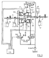
- Figure 3 shows the hydraulic circuit used for moving the shift rails 4 and 5 using double-acting piston and cylinder assemblies 100 and 101 and solenoid-operated valves EV1, EV2 and EV3.
- the axial positions of the pistons 102 and 103 within their respective cylinders are detected by four sensors C1-C4.
- Sensors C1-C4 and valves EV1, EV2 and EV3 are connected to an electronic control system indicated diagrammatically at CS in Figure 3.
- Figure 4 shows in tabular form the solenoid-operated valve which must be activated to change between the three operating modes of the CVT (as will be described below) and also the signals given by the sensors C1-C4 when in each of the modes.
- the hydraulic circuit is binary in operation, that is in order to change between adjacent modes of the CVT it is only necessary to actuate a single solenoid-operated valve EV1, EV2 or EV3.
- the valves EV1-EV3, the sensors C1-C4 and the double-acting cylinders 100 and 101 are all mounted on a removable side-cover of the transmission housing to provide easy serviceability and access.
- the CVT also includes an output gear train 48 which provides a low range, a high range and a reverse drive range thus extending the total overall ratio range of the transmission.
- the output gear train 48 includes a coupler 49 which, when moved to the left from the position shown in Figure 1, engages clutch teeth 50 to couple final output shaft 51 with output shaft 18 and provide the high range of the output gear train.
- Two other gear trains 52, 53 and 54, 55, 56 are provided which can be selectively engaged by operation of a further coupler 57.
- gear train 52, 53 is engaged via clutch teeth 58 and drive is transmitted from output shaft 18 via gears 21, 20, 53, 52 to the final output shaft 51 to provide the low range of the output gear train. If coupler 49 is disengaged as shown at Figure 1 and coupler 57 is moved to the right, gear train 54, 55, 56 is then connected to provide drive from output shaft 18 via gears 21, 20, 56, 55, 54 on to the final output shaft 51 in its reverse range due to the provision of he reverse idler 55 between gears 56 and 54.
- the total overall forward ratio of the CVT is doubled and a reverse drive capability is also provided.
- input shaft 12 travels longitudinally through the transmission to emerge at location 12A.
- This shaft can be used to provide a power-take-off (PTO) facility for the tractor.
- PTO power-take-off
- the transmission arrangement described is particularly compact and fits into a standard existing tractor transmission housing 9 with the addition of a removable dished plate 8 which slightly increases the internal size of the housing and also provides easy access to the hydraulic units and the remainder of the transmission.
- the hydraulic units may be bolted to the inside of the plate 8 for ease of removal and thus optimum serviceability.
- the aperture in the housing which the plate 8 covers is also used for transmission assembly.
- couplers 30, 35, 41 and 46 described above are preferably of the synchromesh type.
- the low ratio of the output gear train 48 is selected by the control system CS of the CVT by moving coupler 57 to the left as viewed in Figure 1 and the control system of the CVT engages the couplers 35 and 41 as shown in Figure 1 in order to connect the sun gear 23 of planetary gear train 10 with the output shaft 18, so that the transmission is running in its first mode, the so-called output coupled condition with the double-acting cylinders 100-101 in the positions shown in Figure 3.
- the hydraulic unit H2 acts as a motor with its swash plate S2 set to give the maximum volumetric displacement condition, as shown in Figure 1, and the hydraulic unit H1 acts as a pump with its swash plate S1 set to give a nil flow rate.
- the pressure in the hydraulic circuit interconnecting units H1 and H2 is dictated by the torque acting on the output shaft 18.
- the torque needed to drive the pump H1 increases as the setting of swash plate S1 is changed to increase its volumetric displacement.
- additional torque is transmitted to output shaft 18 through the output member 17 of epicyclic gear train 10.
- the speed of the unit H2 and the output shaft 18 increases as the volumetric displacement of H1 increases and the transmitted power increases along portion OP of the curve shown in Figure 2.
- the setting of swash plate S1 is progressively changed by the control system to reduce the volumetric displacement of hydraulic unit H2.
- This increases the speed of unit H2 and the output shaft 18 up to a ratio ⁇ 1 at point Q.
- the volumetric displacement of motor H2 is nil and hence pump H1 is hydraulically locked and all the power is transmitted mechanically from the input shaft 12 to the output shaft 18 through the epicyclic gear train 10 which has its sun gear 23 held stationary by the locked unit H1.
- Point Q gives a ratio ⁇ 1 with the hydraulic unit H2 running at its maximum speed but without the transmission of torque.
- valve EV2 which pressurises the left-hand end of piston 103 which is already displaced fully to the right and also pressurises the left-hand end of piston 102 which moves piston 102 to the right.
- This moves shift rail 4 to disengage coupler 41 from clutch teeth 42 thus disengaging gear 37 from output shaft 18 fractionally before engaging coupler 46 with clutch teeth 47 to couple the gear 43 with the reaction member (the sun 25) of the epicyclic gear train 11.
- the tooth numbers of the gears 43, 44, 45, 37, 38, 39, 40 are chosen in order that gears 25 and 43 rotate at the same speed at point Q to enable coupler 46 to be moved quickly in order to obtain a smooth continuity of ratio variation.
- the transmission is operating in its second mode in which the reaction members (the suns 23, 25) of the epicyclic gear trains 10 and 11 are interconnected via the shunt loop.
- unit H1 is still connected to the epicyclic gear train 10 but now works as an hydraulic motor and the unit H2 is connected with the epicyclic train 11 and now works as an hydraulic pump.
- the change from mode two to mode one is made (as can be seen from Figure 4) by actuating valve EV1 which pressurises the right-hand end of piston 102 to move this piston to the left to the position showed in Figure 3.
- the overall output ratio of the transmission can then be varied from ⁇ 1 to ⁇ 2 along portion QR of the curve shown in Figure 2 by varying the swash plate angles of the hydraulic units H1 and H2.
- the hydraulic unit H1 At output ratio ⁇ 2 which corresponds to point R on the curve of Figure 2, the hydraulic unit H1 is in a zero volumetric displacement condition so that the unit H2 is hydraulically locked thus holding the sun 25 of epicyclic gear train 11 locked.
- the gear trains driving the couplers 35 and 30 are arranged to be such that at the point R the couplers rotate at the same speed. This allows the control system to actuate valve EV3 which pressurises the right-hand end of piston 103 to move piston 103 to the left, as viewed in Figure 3.
- the change in the opposite direction from mode three to mode two of the CVT can also be made at point R by actuating valve EV2 which pressurises the left-hand end of both pistons 102 and 103. Since piston 102 is already displaced to the right this has no effect on piston 102 but piston 103 is displaced to the right to move shift rail 5.
- the portion S to T of the curve of Figure 2 represents the regulator slope on the torque/speed characteristic of the engine between the maximum power point and the no-load maximum engine speed condition.
- control system CS of the CVT ensures that whenever the tractor starts from rest the output gear train 48 is in its low range.
- the system then controls the swash plate angles and the couplers, as described above, in order to shift the overall range of the transmission from zero to ⁇ R, as described above.
- control system CS automatically changes to the high range of the output gear train 48, as follows.
- control system CS releases the pressure in the hydraulic shunt loop via an electrically operated check valve (not shown) in the connection between units H1 and H2.
- the system places the range change coupler 57 in its neutral position so that neither gear train 52, 53 nor train 54, 55, 56 is coupled to the output shaft 51.
- the mode and overall output ratio of the CVT is then adjusted in order to minimise the speed differential between output shaft 51 and the high range clutch teeth 50 carried on shaft 18.
- the coupler 49 is then moved by an electro-hydraulic actuating system (not shown) to engage clutch teeth 50 to connect the high range of the output gear train. This is possible because there is a large overlap between the low and high ranges.
- the low to high range change procedure described above produces a very fast change without any jerk and requires no action on the part of the tractor operator, who simply moves a single control lever along a straight gate from a zero speed position up to a maximum speed position, whereupon the control system CS makes the necessary mode and range changes to achieve the speed selected by the operator.
- the forward/reverse drive direction is selected by the tractor operator moving a separate control lever, mounted on the steering column, into either a forward or reverse drive direction selection position.
- the control system reduces the speed of the tractor by changing the modes and, if necessary, the ranges of the CVT to bring the tractor to rest using the maximum engine braking effect without exceeding a predetermined limit of deceleration.
- the system will move the coupler 57 using an electro-hydraulic actuating system (not shown) to select the reverse drive train 54, 55, 56 and will then increase the setting of hydraulic units H1 and H2 and make the necessary mode changes to achieve the speed in reverse selected by the operator.
- the CVT has a region of full power utilisation between ⁇ D and ⁇ R.
- ground speed 0 to 17 Km/hour can be achieved so that all the normal field working operations can be undertaken in low range.
- the high range typically allows ground speeds of 0 to 40 Km/hour and the change between the high and low ranges is typically made at, say, 14 Km/hour without any interruption in the drive capability of the CVT.
- the CVT described above with identical planetary gear trains 10, 11 and two simple gear trains (14, 15 and 20, 21) defining ratios ⁇ 1 and ⁇ 2, is very versatile.
- the variation of speed range is limited by the hydraulic elements for a given engine power.
- a larger range is possible for smaller engine power simply by changing the ratios of the gear trains 14, 15 and 20, 21.
- the output gear train 48 essentially separate from the front variator section, it is simple to adapt the output gear section for any application without altering the variator section.
- the output gear train 48 could be used to supply an overdrive ratio in place of the low range and reverse described above.
- the basic two-shaft layout of the transmission with the second planetary gear train 11 coaxial with the input shaft 12 and PTO shaft 12A and with the first planetary gear train 10 coaxial with the output shaft 51 is allowing the output of the transmission to be taken either at shaft 51 as described or, alternatively, with appropriate internal gearing modifications, coaxial with input/PTO shaft 12/12A. This enables the variator and total transmission to be easily matched to any vehicle kinematic giving great versatility.
- the two shaft layout allows easy use of identically sized sun, planet and annulus gears thus significantly reducing production costs.
Landscapes
- Engineering & Computer Science (AREA)
- General Engineering & Computer Science (AREA)
- Mechanical Engineering (AREA)
- Structure Of Transmissions (AREA)
Abstract
Description
- This invention relates to transmissions and in particular to continuously variable transmissions (CVTs) in which the output ratio of the transmission is variable in a continuous manner between the end limits of its total range.
- It is an object of the present invention to provide a CVT with a wide overall operating range which is suitable for use in an agricultural or industrial tractor.
- Thus according to the present invention there is provided a CVT having an input shaft and an output shaft, first and second epicyclic gear trains each with an input member, an output member and a reaction member, and an hydrostatic shunt loop comprising first and second hydraulically interconnected variable displacement hydraulic units, the input members of both epicyclic gear trains being driven from the input shaft and the output members of both epicyclic gear trains driving the output shaft, first and second drive trains for alternatively coupling the first variable displacement hydraulic unit respectively to either the input shaft or the reaction member of the first epicyclic gear train, third and fourth drive trains for alternatively coupling the second variable displacement hydraulic unit respectively to either the output shaft or the reaction member of the second epicyclic gear train, and a transmission control system for selective operation of the first, second, third and fourth gear trains to operate the transmission in three modes, as follows:
- a) with the second and third gear trains operational to utilise the first epicyclic only with its reaction member connected to the output shaft via the hydrostatic shunt loop;
- b) with the second and fourth gear trains operational to utilise both epicyclics with their reaction members interconnected via the hydrostatic shunt loop, and
- c) with the first and fourth gear trains operational to utilise the second epicyclic only with its reaction member connected to the input shaft via the hydrostatic shunt loop.
- In a preferred arrangement, one epicyclic gear train is coaxial with the input shaft and the other is coaxial with the output shaft and a further output gear train is provided with shafts coaxial with the input and output shafts to extend the overall range of the transmission.
- The output gear train may also include a reverse drive gear train.
- The first and second epicyclic gear trains may have identically sized sun, planet and annulus gears.
- One embodiment of the present invention, as applied to a tractor transmission, will now be described, by way of example only, with reference to the accompanying drawings in which:
- Figure 1 is a diagrammatic section through a CVT embodying the present invention;
- Figure 2 is a graphical representation of the proportion of the total power available transmitted mechanically and hydraulically throughout the entire operating range of the CVT;
- Figure 3 is a diagrammatic representation of a suitable hydraulic circuit for changing the modes of the CVT, and
- Figure 4 is a tabular summary of the operation of the solenoid-operated valves and piston position sensors when in and changing between the modes of the CVT.
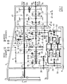
- Referring to Figure 1, this shows a CVT in accordance with the present invention which is particularly suitable for tractor applications and which includes first and second
epicyclic gear trains 10 and 11 and first and second variable displacement hydraulic units H1 and H2 which are hydraulically interconnected viapassages 6 in a connectingblock 7 and which constitute an hydrostatic shunt loop. Typically these units are of the variable swash-plate type, their swash plates being diagrammatically shown at S1 and S2 respectively. The use of the connectingblock 7 ensures minimum pressure drop between H1 and H2. - An
input shaft 12 drives theannulus gear 13 of firstepicyclic gear train 10 viagears annulus gear 16 of the second epicyclic gear train 11. Theplanet carrier 17 of theepicyclic gear 10 is connected to anoutput shaft 18 and similarly theplanet carrier 19 of epicyclic gear 11 is also connected tooutput shaft 18 viagears - Planet
gears 22 carried bycarrier 17 mesh with asun gear 23 which operates as the reaction member ofepicyclic gear train 10. Similarly planet gears 24 of epicyclic gear 11 mesh with sun gear 25 which acts as the reaction member of epicyclic gear 11. - In the arrangement disclosed, the
epicyclic gear trains 10 and 11 have identically sized sun, planet and annulus gears thus significantly reducing production costs. - A first drive train constituted by
gears input shaft 12 via afirst coupler 30 andgears coupler 30 to the left from the position shown in Figure 1 so that thecoupler 30 engagesclutch teeth 32. A second drive train in the form ofgears sun gear 23 ofepicyclic gear train 10 to the hydraulic unit H1. This train is activated when asecond coupler 35 is in the position shown in Figure 1 in whichclutch teeth 33 are engaged. - As shown diagrammatically in Figure 1, the two
couplers single shift rail 5 which is actuated by a double acting hydraulic piston and cylinder assembly 101 (see figure 3) under the control of solenoid operated valves EV2, EV3. Whencoupler 30 is engaged,coupler 35 is disengaged and vice versa. - A third gear train is provided in the form of
gears output shaft 18 when athird coupler 41 engages clutch teeth 42 as shown in Figure 1. - A fourth gear train in the form of
gears fourth coupler 46 is moved to the right from the position shown in Figure 1 to engage theclutch teeth 47. Thecouplers further shift rail 4 which is actuated by another double acting hydraulic piston andcylinder assembly 100 under the control of solenoid operated valves EV1, EV2 (see Figure 3). - Figure 3 shows the hydraulic circuit used for moving the
shift rails cylinder assemblies pistons - Figure 4 shows in tabular form the solenoid-operated valve which must be activated to change between the three operating modes of the CVT (as will be described below) and also the signals given by the sensors C1-C4 when in each of the modes. As can be seen from Figure 4 when the transmission is in each of the modes the
cylinders cylinders - The CVT also includes an
output gear train 48 which provides a low range, a high range and a reverse drive range thus extending the total overall ratio range of the transmission. Theoutput gear train 48 includes acoupler 49 which, when moved to the left from the position shown in Figure 1, engagesclutch teeth 50 to couplefinal output shaft 51 withoutput shaft 18 and provide the high range of the output gear train. Twoother gear trains further coupler 57. Withcoupler 49 disengaged as shown in Figure 1 andcoupler 57 moved to the left from the position shown in Figure 1,gear train clutch teeth 58 and drive is transmitted fromoutput shaft 18 viagears final output shaft 51 to provide the low range of the output gear train. Ifcoupler 49 is disengaged as shown at Figure 1 andcoupler 57 is moved to the right,gear train output shaft 18 viagears final output shaft 51 in its reverse range due to the provision of he reverseidler 55 betweengears - Thus, as will be appreciated, by use of the
output gear train 48, the total overall forward ratio of the CVT is doubled and a reverse drive capability is also provided. - Also,
input shaft 12 travels longitudinally through the transmission to emerge atlocation 12A. This shaft can be used to provide a power-take-off (PTO) facility for the tractor. - The transmission arrangement described is particularly compact and fits into a standard existing
tractor transmission housing 9 with the addition of a removable dished plate 8 which slightly increases the internal size of the housing and also provides easy access to the hydraulic units and the remainder of the transmission. The hydraulic units may be bolted to the inside of the plate 8 for ease of removal and thus optimum serviceability. The aperture in the housing which the plate 8 covers is also used for transmission assembly. - It will be appreciated that the
couplers - Operation of the CVT will now be described with reference to Figure 2, which shows the relative percentage of the total power transmitted mechanically and hydraulically throughout all the operating modes of the transmission.
- In order to move the tractor away from rest, the low ratio of the
output gear train 48 is selected by the control system CS of the CVT by movingcoupler 57 to the left as viewed in Figure 1 and the control system of the CVT engages thecouplers sun gear 23 ofplanetary gear train 10 with theoutput shaft 18, so that the transmission is running in its first mode, the so-called output coupled condition with the double-acting cylinders 100-101 in the positions shown in Figure 3. In this mode the hydraulic unit H2 acts as a motor with its swash plate S2 set to give the maximum volumetric displacement condition, as shown in Figure 1, and the hydraulic unit H1 acts as a pump with its swash plate S1 set to give a nil flow rate. In this condition the pressure in the hydraulic circuit interconnecting units H1 and H2 is dictated by the torque acting on theoutput shaft 18. - To move away from rest the setting of swash plate S1 is progressively changed by the control system to begin the build-up of pumping pressure in unit H1 to overcome the torque on the
output shaft 18. Unit H2 then starts to rotate and to drive the output shaft under a maximum torque defined by the pressure setting of an hydraulic relief valve (not shown) in the connection between units H1 and H2. - The torque needed to drive the pump H1 increases as the setting of swash plate S1 is changed to increase its volumetric displacement. As a consequence, additional torque is transmitted to
output shaft 18 through theoutput member 17 ofepicyclic gear train 10. In addition, the speed of the unit H2 and theoutput shaft 18 increases as the volumetric displacement of H1 increases and the transmitted power increases along portion OP of the curve shown in Figure 2. - When unit H1 achieves its maximum volumetric displacement, the maximum power is transmitted to the output shaft and this corresponds to point P in Figure 2. A small part of this power is transmitted through the hydraulic shunt loop provided by Unit H1 and H2. The ratio obtained at this point P is αD, as shown in Figure 2.
- The range from rest (α = o) to αD is a starting range and the tractor can move away from rest without any loss of energy as long as the torque on the output shaft at rest does not give rise to a shunt loop hydraulic pressure which exceeds the relief pressure setting of the hydraulic relief valve in the connection between units H1 and H2.
- If the resisting torque on the output shaft gives rise to a pressure which is higher than the relief valve setting, the relief valve will open resulting in a loss of energy but since the torque of unit H1 increases with the volumetric displacement so the torque transmitted to the output shaft will nevertheless increase up to the maximum torque available at ratio αD at point P.
- To increase the output speed above αD along portion PQ of the curve, the setting of swash plate S1 is progressively changed by the control system to reduce the volumetric displacement of hydraulic unit H2. This increases the speed of unit H2 and the
output shaft 18 up to a ratio α1 at point Q. At point Q the volumetric displacement of motor H2 is nil and hence pump H1 is hydraulically locked and all the power is transmitted mechanically from theinput shaft 12 to theoutput shaft 18 through theepicyclic gear train 10 which has itssun gear 23 held stationary by the locked unit H1. Point Q gives a ratio α1 with the hydraulic unit H2 running at its maximum speed but without the transmission of torque. - At point Q the control system actuates valve EV2 which pressurises the left-hand end of
piston 103 which is already displaced fully to the right and also pressurises the left-hand end ofpiston 102 which movespiston 102 to the right. This movesshift rail 4 to disengagecoupler 41 from clutch teeth 42 thus disengaginggear 37 fromoutput shaft 18 fractionally before engagingcoupler 46 withclutch teeth 47 to couple thegear 43 with the reaction member (the sun 25) of the epicyclic gear train 11. The tooth numbers of thegears coupler 46 to be moved quickly in order to obtain a smooth continuity of ratio variation. - After this change at point Q, the transmission is operating in its second mode in which the reaction members (the
suns 23, 25) of theepicyclic gear trains 10 and 11 are interconnected via the shunt loop. In this mode unit H1 is still connected to theepicyclic gear train 10 but now works as an hydraulic motor and the unit H2 is connected with the epicyclic train 11 and now works as an hydraulic pump. The change from mode two to mode one is made (as can be seen from Figure 4) by actuating valve EV1 which pressurises the right-hand end ofpiston 102 to move this piston to the left to the position showed in Figure 3. - The overall output ratio of the transmission can then be varied from α1 to α2 along portion QR of the curve shown in Figure 2 by varying the swash plate angles of the hydraulic units H1 and H2.
- At output ratio α2 which corresponds to point R on the curve of Figure 2, the hydraulic unit H1 is in a zero volumetric displacement condition so that the unit H2 is hydraulically locked thus holding the sun 25 of epicyclic gear train 11 locked. The gear trains driving the
couplers piston 103 to movepiston 103 to the left, as viewed in Figure 3. This in turn moves shiftrail 5 to engagecoupler 30 withclutch teeth 32 fractionally beforecoupler 35 is disengaged fromclutch teeth 33 so that the sun gear 25 of epicyclic gear train 11 is now driven from theinput shaft 12 via the hydraulic units H1 and H2 and the CVT is operating in its third mode. The swash plate of hydraulic unit H1 is opened by the control system CS to begin to drive H2 which in turn begins to drive the sun gear 25 of epicyclic gear 11 so that the speed ofplanet carrier 19 increases, thus increasing the overall output ratio of the transmission up to ratio αR at point S in Figure 2. - The change in the opposite direction from mode three to mode two of the CVT can also be made at point R by actuating valve EV2 which pressurises the left-hand end of both
pistons piston 102 is already displaced to the right this has no effect onpiston 102 butpiston 103 is displaced to the right to moveshift rail 5. - The portion S to T of the curve of Figure 2 represents the regulator slope on the torque/speed characteristic of the engine between the maximum power point and the no-load maximum engine speed condition.
- As described above, the control system CS of the CVT ensures that whenever the tractor starts from rest the
output gear train 48 is in its low range. The system then controls the swash plate angles and the couplers, as described above, in order to shift the overall range of the transmission from zero to αR, as described above. - When the output ratio αR is achieved at point S, the control system CS automatically changes to the high range of the
output gear train 48, as follows. - Firstly, the control system CS releases the pressure in the hydraulic shunt loop via an electrically operated check valve (not shown) in the connection between units H1 and H2. The system then places the
range change coupler 57 in its neutral position so that neithergear train train output shaft 51. The mode and overall output ratio of the CVT is then adjusted in order to minimise the speed differential betweenoutput shaft 51 and the high rangeclutch teeth 50 carried onshaft 18. Thecoupler 49 is then moved by an electro-hydraulic actuating system (not shown) to engageclutch teeth 50 to connect the high range of the output gear train. This is possible because there is a large overlap between the low and high ranges. - The low to high range change procedure described above produces a very fast change without any jerk and requires no action on the part of the tractor operator, who simply moves a single control lever along a straight gate from a zero speed position up to a maximum speed position, whereupon the control system CS makes the necessary mode and range changes to achieve the speed selected by the operator.
- The forward/reverse drive direction is selected by the tractor operator moving a separate control lever, mounted on the steering column, into either a forward or reverse drive direction selection position.
- If the tractor is moving in the forward direction and reverse is selected by the operator, the control system reduces the speed of the tractor by changing the modes and, if necessary, the ranges of the CVT to bring the tractor to rest using the maximum engine braking effect without exceeding a predetermined limit of deceleration. When the tractor is at rest and the output ratio α of the CVT is zero, the system will move the
coupler 57 using an electro-hydraulic actuating system (not shown) to select thereverse drive train - As is evident from the above and as can be seen from Figure 2, the CVT has a region of full power utilisation between αD and αR. Typically, when the CVT is operating with the low range of
output gear train 48 engaged, ground speed of 0 to 17 Km/hour can be achieved so that all the normal field working operations can be undertaken in low range. - The high range typically allows ground speeds of 0 to 40 Km/hour and the change between the high and low ranges is typically made at, say, 14 Km/hour without any interruption in the drive capability of the CVT.
- The CVT described above, with identical
planetary gear trains 10, 11 and two simple gear trains (14, 15 and 20, 21) defining ratios α1 and α2, is very versatile. The variation of speed range is limited by the hydraulic elements for a given engine power. However, a larger range is possible for smaller engine power simply by changing the ratios of thegear trains output gear train 48 essentially separate from the front variator section, it is simple to adapt the output gear section for any application without altering the variator section. For instance, theoutput gear train 48 could be used to supply an overdrive ratio in place of the low range and reverse described above. - Also the basic two-shaft layout of the transmission with the second planetary gear train 11 coaxial with the
input shaft 12 andPTO shaft 12A and with the firstplanetary gear train 10 coaxial with theoutput shaft 51 is allowing the output of the transmission to be taken either atshaft 51 as described or, alternatively, with appropriate internal gearing modifications, coaxial with input/PTO shaft 12/12A. This enables the variator and total transmission to be easily matched to any vehicle kinematic giving great versatility. - Also, as mentioned above, the two shaft layout allows easy use of identically sized sun, planet and annulus gears thus significantly reducing production costs.
Claims (8)
Applications Claiming Priority (2)
| Application Number | Priority Date | Filing Date | Title |
|---|---|---|---|
| GB9213703 | 1992-06-27 | ||
| GB929213703A GB9213703D0 (en) | 1992-06-27 | 1992-06-27 | Transmissions |
Publications (2)
| Publication Number | Publication Date |
|---|---|
| EP0577282A1 true EP0577282A1 (en) | 1994-01-05 |
| EP0577282B1 EP0577282B1 (en) | 1996-08-14 |
Family
ID=10717845
Family Applications (1)
| Application Number | Title | Priority Date | Filing Date |
|---|---|---|---|
| EP93304580A Expired - Lifetime EP0577282B1 (en) | 1992-06-27 | 1993-06-11 | Transmission |
Country Status (4)
| Country | Link |
|---|---|
| US (1) | US5421790A (en) |
| EP (1) | EP0577282B1 (en) |
| DE (1) | DE69303995T2 (en) |
| GB (2) | GB9213703D0 (en) |
Cited By (20)
| Publication number | Priority date | Publication date | Assignee | Title |
|---|---|---|---|---|
| EP0728962A2 (en) * | 1995-02-22 | 1996-08-28 | Deere & Company | Hydromechanical power transmission |
| EP0818643A2 (en) * | 1996-07-13 | 1998-01-14 | CLAAS KGaA | Split-torque hydromechanical transmission |
| EP1146252A1 (en) * | 1998-10-26 | 2001-10-17 | Yanmar Diesel Engine Co. Ltd. | Continuously variable transmission |
| WO2005019697A1 (en) * | 2003-08-22 | 2005-03-03 | Same Deutz-Fahr Group S.P.A | Hydromechanical transmission for agricultural tractors |
| EP1541898A3 (en) * | 2003-12-12 | 2006-02-08 | CNH Italia S.p.A. | CVT transmission for motor vehicles, in particular for tractors |
| WO2008015549A2 (en) * | 2006-08-03 | 2008-02-07 | Toyota Jidosha Kabushiki Kaisha | Power split dual input shaft transmission for vehicle |
| WO2009047033A1 (en) | 2007-10-02 | 2009-04-16 | Zf Friedrichshafen Ag | Transmission device for a vehicle, having a variator |
| FR2928878A1 (en) * | 2008-03-19 | 2009-09-25 | Renault Sas | GEARBOX FOR HYBRID VEHICLE. |
| CN101501366B (en) * | 2006-08-03 | 2011-12-21 | 丰田自动车株式会社 | Power split dual input shaft transmission for vehicle |
| US8262530B2 (en) | 2007-10-02 | 2012-09-11 | Zf Friedrichshafen Ag | Power-branched transmission |
| US8262525B2 (en) | 2007-10-02 | 2012-09-11 | Zf Friedrichshafen Ag | Hydrostatic-mechanical power split transmission |
| US8287414B2 (en) | 2007-10-02 | 2012-10-16 | Zf Friedrichshafen Ag | Transmission device having a variator |
| US8323138B2 (en) | 2007-10-02 | 2012-12-04 | Zf Friedrichshafen Ag | Power split transmission |
| US8328676B2 (en) | 2007-10-02 | 2012-12-11 | Zf Friedrichshafen Ag | Power split transmission |
| WO2012177187A1 (en) * | 2011-06-21 | 2012-12-27 | Volvo Construction Equipment Ab | A method for controlling a power split continuously variable transmission and a power split continuously variable transmission |
| US8393988B2 (en) | 2007-10-02 | 2013-03-12 | Zf Friedrichshafen Ag | Transmission device for a vehicle |
| US8424633B2 (en) | 2007-10-02 | 2013-04-23 | Zf Friedrichshafen Ag | Variable transmission device for a vehicle |
| US8752374B2 (en) | 2007-10-02 | 2014-06-17 | Zf Friedrichshafen Ag | Device for adjusting the stroke volume of hydraulic piston machines |
| US8756931B2 (en) | 2007-10-02 | 2014-06-24 | Zf Friedrichshafen Ag | Device for adjusting the stroke volume of hydraulic piston machines |
| RU2548309C2 (en) * | 2009-06-05 | 2015-04-20 | Дир Энд Компани | Hydraulic transmission with shifting under load, with energy recovery and operation at low speed |
Families Citing this family (12)
| Publication number | Priority date | Publication date | Assignee | Title |
|---|---|---|---|---|
| DE69316383T2 (en) * | 1992-10-06 | 1998-05-20 | J.C. Bamford Excavators Ltd., Uttoxeter, Staffordshire | CONTINUOUSLY BRANCHING GEARBOX |
| US5618242A (en) * | 1995-09-06 | 1997-04-08 | Wu; Cheng-Hsiung | Apparatus for torque-converter clutch transmission |
| DE19718461A1 (en) * | 1997-04-30 | 1998-11-05 | Neunkirchener Maschinen Und Ac | Hybrid transmission |
| DE59707224D1 (en) * | 1997-09-09 | 2002-06-13 | Zahnradfabrik Friedrichshafen | Power split transmission and its installation in a transmission housing |
| AUPP373798A0 (en) * | 1998-05-27 | 1998-06-18 | Williames, Geoffrey Allan | Vehicle powertrains |
| DE19943335A1 (en) * | 1999-09-10 | 2001-04-05 | Zahnradfabrik Friedrichshafen | Mathematical modeling system for maximum and minimum achievable accelerations of electrohydraulically-operated belt variator, includes laminar and turbulent hydraulic system modeling assumptions |
| JP4284024B2 (en) | 2001-01-18 | 2009-06-24 | サウアー ダンフォス インコーポレイテッド | Small engine transmission |
| JP2002243018A (en) * | 2001-02-14 | 2002-08-28 | Sauer-Danfoss-Daikin Ltd | Hydromechanical transmission and vehicle mounted with this transmission |
| US6904997B2 (en) * | 2001-05-31 | 2005-06-14 | Sauer-Danfoss, Inc. | Compact vehicle transmission |
| US6595885B1 (en) | 2001-12-28 | 2003-07-22 | Caterpillar Inc | Transmission control system and method |
| DE10322232B4 (en) * | 2003-05-17 | 2012-02-02 | Zf Friedrichshafen Ag | Power split transmission |
| WO2008045368A2 (en) * | 2006-10-05 | 2008-04-17 | Folsom Technologies International Llc | Hydromechanical continuously variable transaxle transmissions |
Citations (4)
| Publication number | Priority date | Publication date | Assignee | Title |
|---|---|---|---|---|
| DE1113621B (en) * | 1957-07-19 | 1961-09-07 | Eduard Woydt Dr Ing | Epicyclic gear with power split into mechanical and hydrostatic branches |
| DE2820025A1 (en) * | 1976-12-04 | 1979-11-29 | Jarchow Friedrich | Steplessly adjustable transmission unit - has output epicyclic gear train running idle with input one retroactively coupled |
| EP0365772A2 (en) * | 1988-10-22 | 1990-05-02 | MAN Nutzfahrzeuge Aktiengesellschaft | Propulsion device, particularly for an extreme cross-country wheeled vehicle |
| EP0464413A1 (en) * | 1990-07-06 | 1992-01-08 | Claas Ohg | Multiple-ratio hydrostatic-mechanical split-torque powershift transmission |
Family Cites Families (7)
| Publication number | Priority date | Publication date | Assignee | Title |
|---|---|---|---|---|
| FR1584179A (en) * | 1968-08-29 | 1969-12-12 | ||
| US3580107A (en) * | 1968-10-21 | 1971-05-25 | Urs Systems Corp | Transmission |
| US3888139A (en) * | 1971-06-21 | 1975-06-10 | Orshansky Transmission Corp | Hydromechanical transmission |
| IL64739A (en) * | 1982-01-10 | 1986-03-31 | Int Services Ind Dev Corp | Vehicle drive system |
| FR2531173B1 (en) * | 1982-07-30 | 1988-09-23 | Renault | HYDRAULIC POWER BYPASS TRANSMISSION |
| DE3344042A1 (en) * | 1983-12-06 | 1985-06-27 | Claas Ohg, 4834 Harsewinkel | Continuously variable transmission |
| EP0195452B1 (en) * | 1985-03-21 | 1990-10-17 | Friedrich Prof. Dr.-Ing. Jarchow | Contunuously variable compound power shift transmission of the range-speed type with multiple power path |
-
1992
- 1992-06-27 GB GB929213703A patent/GB9213703D0/en active Pending
-
1993
- 1993-06-11 EP EP93304580A patent/EP0577282B1/en not_active Expired - Lifetime
- 1993-06-11 DE DE69303995T patent/DE69303995T2/en not_active Expired - Fee Related
- 1993-06-21 GB GB9312755A patent/GB2268237B/en not_active Revoked
- 1993-06-22 US US08/081,395 patent/US5421790A/en not_active Expired - Lifetime
Patent Citations (4)
| Publication number | Priority date | Publication date | Assignee | Title |
|---|---|---|---|---|
| DE1113621B (en) * | 1957-07-19 | 1961-09-07 | Eduard Woydt Dr Ing | Epicyclic gear with power split into mechanical and hydrostatic branches |
| DE2820025A1 (en) * | 1976-12-04 | 1979-11-29 | Jarchow Friedrich | Steplessly adjustable transmission unit - has output epicyclic gear train running idle with input one retroactively coupled |
| EP0365772A2 (en) * | 1988-10-22 | 1990-05-02 | MAN Nutzfahrzeuge Aktiengesellschaft | Propulsion device, particularly for an extreme cross-country wheeled vehicle |
| EP0464413A1 (en) * | 1990-07-06 | 1992-01-08 | Claas Ohg | Multiple-ratio hydrostatic-mechanical split-torque powershift transmission |
Cited By (30)
| Publication number | Priority date | Publication date | Assignee | Title |
|---|---|---|---|---|
| EP0728962A2 (en) * | 1995-02-22 | 1996-08-28 | Deere & Company | Hydromechanical power transmission |
| EP0728962A3 (en) * | 1995-02-22 | 1997-11-12 | Deere & Company | Hydromechanical power transmission |
| EP0818643A2 (en) * | 1996-07-13 | 1998-01-14 | CLAAS KGaA | Split-torque hydromechanical transmission |
| EP0818643A3 (en) * | 1996-07-13 | 1999-02-03 | CLAAS KGaA | Split-torque hydromechanical transmission |
| EP1146252A1 (en) * | 1998-10-26 | 2001-10-17 | Yanmar Diesel Engine Co. Ltd. | Continuously variable transmission |
| EP1146252A4 (en) * | 1998-10-26 | 2003-04-09 | Yanmar Diesel Engine Co | Continuously variable transmission |
| WO2005019697A1 (en) * | 2003-08-22 | 2005-03-03 | Same Deutz-Fahr Group S.P.A | Hydromechanical transmission for agricultural tractors |
| US7465245B2 (en) | 2003-08-22 | 2008-12-16 | Same Deutz-Fahr Group S.P.A. | Hydromechanical transmission for agricultural tractors |
| EP1541898A3 (en) * | 2003-12-12 | 2006-02-08 | CNH Italia S.p.A. | CVT transmission for motor vehicles, in particular for tractors |
| WO2008015549A2 (en) * | 2006-08-03 | 2008-02-07 | Toyota Jidosha Kabushiki Kaisha | Power split dual input shaft transmission for vehicle |
| WO2008015549A3 (en) * | 2006-08-03 | 2008-04-17 | Toyota Motor Co Ltd | Power split dual input shaft transmission for vehicle |
| CN101501366B (en) * | 2006-08-03 | 2011-12-21 | 丰田自动车株式会社 | Power split dual input shaft transmission for vehicle |
| US8251848B2 (en) | 2006-08-03 | 2012-08-28 | Toyota Jidosha Kabushiki Kaisha | Power split dual input shaft transmission for vehicle |
| US8328676B2 (en) | 2007-10-02 | 2012-12-11 | Zf Friedrichshafen Ag | Power split transmission |
| US8323138B2 (en) | 2007-10-02 | 2012-12-04 | Zf Friedrichshafen Ag | Power split transmission |
| US8752374B2 (en) | 2007-10-02 | 2014-06-17 | Zf Friedrichshafen Ag | Device for adjusting the stroke volume of hydraulic piston machines |
| US8424633B2 (en) | 2007-10-02 | 2013-04-23 | Zf Friedrichshafen Ag | Variable transmission device for a vehicle |
| US8262530B2 (en) | 2007-10-02 | 2012-09-11 | Zf Friedrichshafen Ag | Power-branched transmission |
| US8262525B2 (en) | 2007-10-02 | 2012-09-11 | Zf Friedrichshafen Ag | Hydrostatic-mechanical power split transmission |
| US8287414B2 (en) | 2007-10-02 | 2012-10-16 | Zf Friedrichshafen Ag | Transmission device having a variator |
| US8756931B2 (en) | 2007-10-02 | 2014-06-24 | Zf Friedrichshafen Ag | Device for adjusting the stroke volume of hydraulic piston machines |
| WO2009047033A1 (en) | 2007-10-02 | 2009-04-16 | Zf Friedrichshafen Ag | Transmission device for a vehicle, having a variator |
| US8414439B2 (en) | 2007-10-02 | 2013-04-09 | Zf Friedrichshafen Ag | Transmission device for a vehicle, having a variator |
| US8393988B2 (en) | 2007-10-02 | 2013-03-12 | Zf Friedrichshafen Ag | Transmission device for a vehicle |
| WO2009122109A3 (en) * | 2008-03-19 | 2009-11-26 | Renault S.A.S | Transmission for hybrid vehicle |
| FR2928878A1 (en) * | 2008-03-19 | 2009-09-25 | Renault Sas | GEARBOX FOR HYBRID VEHICLE. |
| WO2009122109A2 (en) * | 2008-03-19 | 2009-10-08 | Renault S.A.S | Transmission for hybrid vehicle |
| RU2548309C2 (en) * | 2009-06-05 | 2015-04-20 | Дир Энд Компани | Hydraulic transmission with shifting under load, with energy recovery and operation at low speed |
| WO2012177187A1 (en) * | 2011-06-21 | 2012-12-27 | Volvo Construction Equipment Ab | A method for controlling a power split continuously variable transmission and a power split continuously variable transmission |
| CN103635715A (en) * | 2011-06-21 | 2014-03-12 | 沃尔沃建筑设备公司 | A method for controlling a power split continuously variable transmission and a power split continuously variable transmission |
Also Published As
| Publication number | Publication date |
|---|---|
| GB9213703D0 (en) | 1992-08-12 |
| GB2268237A (en) | 1994-01-05 |
| GB2268237B (en) | 1995-04-05 |
| DE69303995T2 (en) | 1997-03-06 |
| US5421790A (en) | 1995-06-06 |
| GB9312755D0 (en) | 1993-08-04 |
| DE69303995D1 (en) | 1996-09-19 |
| EP0577282B1 (en) | 1996-08-14 |
Similar Documents
| Publication | Publication Date | Title |
|---|---|---|
| EP0577282B1 (en) | Transmission | |
| CN100482975C (en) | Four mode hydro-mechanical transmission | |
| US5193416A (en) | Mechanical-hydraulic transmission gear system and method of controlling power transmission using the system | |
| US4286477A (en) | Steplessly adjustable variable-speed hydrostatic-mechanical composite transmission | |
| EP2153087B1 (en) | Transmission module and transmission assembly method | |
| US4304151A (en) | Stepless composite hydrostatic-mechanical transmission | |
| KR101454057B1 (en) | Power split transmission | |
| US7357744B2 (en) | Hydro-mechanical continuously variable transmission | |
| US5946983A (en) | Hydrostatic mechanical power transmission system particularly hydromechanical transmission for industrial and farming machines and vehicles in general | |
| EP2158417B1 (en) | Vehicle transmission | |
| TW333504B (en) | Multi-range, hydromechanical transmission for motor vehicles | |
| US4354400A (en) | Hydromechanical transmission | |
| US3722324A (en) | Hydromechanical transmission | |
| EP2860426B1 (en) | Hydro-mechanical Transmission | |
| EP0558748B1 (en) | Hydrostatic-mechanical power transmission system | |
| EP4123199A1 (en) | Transmission structure | |
| EP0754883B1 (en) | Mechanical-hydraulic transmission gear system and method of controlling power transmission using the system | |
| US5026333A (en) | Infinitely variable driving and steering transmission mechanism for track-laying vehicles | |
| US3213712A (en) | Hydromechanical transmission with countershaft gearing | |
| CS376790A2 (en) | Hydrostatic mechanical high-duty gearbox with graduated output | |
| US4024775A (en) | Hydrostatic mechanical transmission and controls therefor | |
| JPH03134368A (en) | Hydraulic controller of transmission | |
| RU2399817C2 (en) | Stepless transmission | |
| US5267911A (en) | Hydromechanically infinitely variable transmission, with power splitting, particularly for motor vehicles | |
| US6939261B1 (en) | Compact vehicle transmission |
Legal Events
| Date | Code | Title | Description |
|---|---|---|---|
| PUAI | Public reference made under article 153(3) epc to a published international application that has entered the european phase |
Free format text: ORIGINAL CODE: 0009012 |
|
| AK | Designated contracting states |
Kind code of ref document: A1 Designated state(s): DE FR GB |
|
| 17P | Request for examination filed |
Effective date: 19940513 |
|
| 17Q | First examination report despatched |
Effective date: 19950515 |
|
| GRAH | Despatch of communication of intention to grant a patent |
Free format text: ORIGINAL CODE: EPIDOS IGRA |
|
| GRAH | Despatch of communication of intention to grant a patent |
Free format text: ORIGINAL CODE: EPIDOS IGRA |
|
| GRAH | Despatch of communication of intention to grant a patent |
Free format text: ORIGINAL CODE: EPIDOS IGRA |
|
| GRAH | Despatch of communication of intention to grant a patent |
Free format text: ORIGINAL CODE: EPIDOS IGRA |
|
| GRAA | (expected) grant |
Free format text: ORIGINAL CODE: 0009210 |
|
| AK | Designated contracting states |
Kind code of ref document: B1 Designated state(s): DE FR GB |
|
| REF | Corresponds to: |
Ref document number: 69303995 Country of ref document: DE Date of ref document: 19960919 |
|
| ET | Fr: translation filed | ||
| ET | Fr: translation filed | ||
| PLBE | No opposition filed within time limit |
Free format text: ORIGINAL CODE: 0009261 |
|
| STAA | Information on the status of an ep patent application or granted ep patent |
Free format text: STATUS: NO OPPOSITION FILED WITHIN TIME LIMIT |
|
| 26N | No opposition filed | ||
| REG | Reference to a national code |
Ref country code: FR Ref legal event code: TP Ref country code: FR Ref legal event code: CD |
|
| REG | Reference to a national code |
Ref country code: GB Ref legal event code: IF02 |
|
| PGFP | Annual fee paid to national office [announced via postgrant information from national office to epo] |
Ref country code: DE Payment date: 20070524 Year of fee payment: 15 |
|
| PGFP | Annual fee paid to national office [announced via postgrant information from national office to epo] |
Ref country code: GB Payment date: 20070517 Year of fee payment: 15 |
|
| PGFP | Annual fee paid to national office [announced via postgrant information from national office to epo] |
Ref country code: FR Payment date: 20070515 Year of fee payment: 15 |
|
| GBPC | Gb: european patent ceased through non-payment of renewal fee |
Effective date: 20080611 |
|
| REG | Reference to a national code |
Ref country code: FR Ref legal event code: ST Effective date: 20090228 |
|
| PG25 | Lapsed in a contracting state [announced via postgrant information from national office to epo] |
Ref country code: DE Free format text: LAPSE BECAUSE OF NON-PAYMENT OF DUE FEES Effective date: 20090101 |
|
| PG25 | Lapsed in a contracting state [announced via postgrant information from national office to epo] |
Ref country code: GB Free format text: LAPSE BECAUSE OF NON-PAYMENT OF DUE FEES Effective date: 20080611 |
|
| PG25 | Lapsed in a contracting state [announced via postgrant information from national office to epo] |
Ref country code: FR Free format text: LAPSE BECAUSE OF NON-PAYMENT OF DUE FEES Effective date: 20080630 |