EP0831252A2 - Continously variable transmission,particularly with hydrostatic torque splitting - Google Patents
Continously variable transmission,particularly with hydrostatic torque splitting Download PDFInfo
- Publication number
- EP0831252A2 EP0831252A2 EP97116412A EP97116412A EP0831252A2 EP 0831252 A2 EP0831252 A2 EP 0831252A2 EP 97116412 A EP97116412 A EP 97116412A EP 97116412 A EP97116412 A EP 97116412A EP 0831252 A2 EP0831252 A2 EP 0831252A2
- Authority
- EP
- European Patent Office
- Prior art keywords
- hydrostatic
- transmission
- gear
- brake
- signal
- Prior art date
- Legal status (The legal status is an assumption and is not a legal conclusion. Google has not performed a legal analysis and makes no representation as to the accuracy of the status listed.)
- Withdrawn
Links
Images


Classifications
-
- F—MECHANICAL ENGINEERING; LIGHTING; HEATING; WEAPONS; BLASTING
- F16—ENGINEERING ELEMENTS AND UNITS; GENERAL MEASURES FOR PRODUCING AND MAINTAINING EFFECTIVE FUNCTIONING OF MACHINES OR INSTALLATIONS; THERMAL INSULATION IN GENERAL
- F16D—COUPLINGS FOR TRANSMITTING ROTATION; CLUTCHES; BRAKES
- F16D57/00—Liquid-resistance brakes; Brakes using the internal friction of fluids or fluid-like media, e.g. powders
- F16D57/06—Liquid-resistance brakes; Brakes using the internal friction of fluids or fluid-like media, e.g. powders comprising a pump circulating fluid, braking being effected by throttling of the circulation
-
- B—PERFORMING OPERATIONS; TRANSPORTING
- B60—VEHICLES IN GENERAL
- B60T—VEHICLE BRAKE CONTROL SYSTEMS OR PARTS THEREOF; BRAKE CONTROL SYSTEMS OR PARTS THEREOF, IN GENERAL; ARRANGEMENT OF BRAKING ELEMENTS ON VEHICLES IN GENERAL; PORTABLE DEVICES FOR PREVENTING UNWANTED MOVEMENT OF VEHICLES; VEHICLE MODIFICATIONS TO FACILITATE COOLING OF BRAKES
- B60T1/00—Arrangements of braking elements, i.e. of those parts where braking effect occurs specially for vehicles
- B60T1/02—Arrangements of braking elements, i.e. of those parts where braking effect occurs specially for vehicles acting by retarding wheels
- B60T1/08—Arrangements of braking elements, i.e. of those parts where braking effect occurs specially for vehicles acting by retarding wheels using fluid or powdered medium
- B60T1/093—Arrangements of braking elements, i.e. of those parts where braking effect occurs specially for vehicles acting by retarding wheels using fluid or powdered medium in hydrostatic, i.e. positive displacement, retarders
-
- B—PERFORMING OPERATIONS; TRANSPORTING
- B60—VEHICLES IN GENERAL
- B60T—VEHICLE BRAKE CONTROL SYSTEMS OR PARTS THEREOF; BRAKE CONTROL SYSTEMS OR PARTS THEREOF, IN GENERAL; ARRANGEMENT OF BRAKING ELEMENTS ON VEHICLES IN GENERAL; PORTABLE DEVICES FOR PREVENTING UNWANTED MOVEMENT OF VEHICLES; VEHICLE MODIFICATIONS TO FACILITATE COOLING OF BRAKES
- B60T10/00—Control or regulation for continuous braking making use of fluid or powdered medium, e.g. for use when descending a long slope
- B60T10/04—Control or regulation for continuous braking making use of fluid or powdered medium, e.g. for use when descending a long slope with hydrostatic brake
-
- B—PERFORMING OPERATIONS; TRANSPORTING
- B60—VEHICLES IN GENERAL
- B60T—VEHICLE BRAKE CONTROL SYSTEMS OR PARTS THEREOF; BRAKE CONTROL SYSTEMS OR PARTS THEREOF, IN GENERAL; ARRANGEMENT OF BRAKING ELEMENTS ON VEHICLES IN GENERAL; PORTABLE DEVICES FOR PREVENTING UNWANTED MOVEMENT OF VEHICLES; VEHICLE MODIFICATIONS TO FACILITATE COOLING OF BRAKES
- B60T17/00—Component parts, details, or accessories of power brake systems not covered by groups B60T8/00, B60T13/00 or B60T15/00, or presenting other characteristic features
- B60T17/18—Safety devices; Monitoring
- B60T17/22—Devices for monitoring or checking brake systems; Signal devices
-
- B—PERFORMING OPERATIONS; TRANSPORTING
- B60—VEHICLES IN GENERAL
- B60K—ARRANGEMENT OR MOUNTING OF PROPULSION UNITS OR OF TRANSMISSIONS IN VEHICLES; ARRANGEMENT OR MOUNTING OF PLURAL DIVERSE PRIME-MOVERS IN VEHICLES; AUXILIARY DRIVES FOR VEHICLES; INSTRUMENTATION OR DASHBOARDS FOR VEHICLES; ARRANGEMENTS IN CONNECTION WITH COOLING, AIR INTAKE, GAS EXHAUST OR FUEL SUPPLY OF PROPULSION UNITS IN VEHICLES
- B60K17/00—Arrangement or mounting of transmissions in vehicles
- B60K17/04—Arrangement or mounting of transmissions in vehicles characterised by arrangement, location, or kind of gearing
- B60K17/06—Arrangement or mounting of transmissions in vehicles characterised by arrangement, location, or kind of gearing of change-speed gearing
-
- B—PERFORMING OPERATIONS; TRANSPORTING
- B60—VEHICLES IN GENERAL
- B60T—VEHICLE BRAKE CONTROL SYSTEMS OR PARTS THEREOF; BRAKE CONTROL SYSTEMS OR PARTS THEREOF, IN GENERAL; ARRANGEMENT OF BRAKING ELEMENTS ON VEHICLES IN GENERAL; PORTABLE DEVICES FOR PREVENTING UNWANTED MOVEMENT OF VEHICLES; VEHICLE MODIFICATIONS TO FACILITATE COOLING OF BRAKES
- B60T8/00—Arrangements for adjusting wheel-braking force to meet varying vehicular or ground-surface conditions, e.g. limiting or varying distribution of braking force
- B60T8/32—Arrangements for adjusting wheel-braking force to meet varying vehicular or ground-surface conditions, e.g. limiting or varying distribution of braking force responsive to a speed condition, e.g. acceleration or deceleration
- B60T8/321—Arrangements for adjusting wheel-braking force to meet varying vehicular or ground-surface conditions, e.g. limiting or varying distribution of braking force responsive to a speed condition, e.g. acceleration or deceleration deceleration
- B60T8/3215—Systems characterised by having means acting on components of the drive line, e.g. retarder, clutch or differential gear
-
- B—PERFORMING OPERATIONS; TRANSPORTING
- B60—VEHICLES IN GENERAL
- B60T—VEHICLE BRAKE CONTROL SYSTEMS OR PARTS THEREOF; BRAKE CONTROL SYSTEMS OR PARTS THEREOF, IN GENERAL; ARRANGEMENT OF BRAKING ELEMENTS ON VEHICLES IN GENERAL; PORTABLE DEVICES FOR PREVENTING UNWANTED MOVEMENT OF VEHICLES; VEHICLE MODIFICATIONS TO FACILITATE COOLING OF BRAKES
- B60T8/00—Arrangements for adjusting wheel-braking force to meet varying vehicular or ground-surface conditions, e.g. limiting or varying distribution of braking force
- B60T8/32—Arrangements for adjusting wheel-braking force to meet varying vehicular or ground-surface conditions, e.g. limiting or varying distribution of braking force responsive to a speed condition, e.g. acceleration or deceleration
- B60T8/34—Arrangements for adjusting wheel-braking force to meet varying vehicular or ground-surface conditions, e.g. limiting or varying distribution of braking force responsive to a speed condition, e.g. acceleration or deceleration having a fluid pressure regulator responsive to a speed condition
- B60T8/36—Arrangements for adjusting wheel-braking force to meet varying vehicular or ground-surface conditions, e.g. limiting or varying distribution of braking force responsive to a speed condition, e.g. acceleration or deceleration having a fluid pressure regulator responsive to a speed condition including a pilot valve responding to an electromagnetic force
- B60T8/3615—Electromagnetic valves specially adapted for anti-lock brake and traction control systems
- B60T8/3675—Electromagnetic valves specially adapted for anti-lock brake and traction control systems integrated in modulator units
- B60T8/368—Electromagnetic valves specially adapted for anti-lock brake and traction control systems integrated in modulator units combined with other mechanical components, e.g. pump units, master cylinders
- B60T8/3685—Electromagnetic valves specially adapted for anti-lock brake and traction control systems integrated in modulator units combined with other mechanical components, e.g. pump units, master cylinders characterised by the mounting of the modulator unit onto the vehicle
-
- B—PERFORMING OPERATIONS; TRANSPORTING
- B60—VEHICLES IN GENERAL
- B60W—CONJOINT CONTROL OF VEHICLE SUB-UNITS OF DIFFERENT TYPE OR DIFFERENT FUNCTION; CONTROL SYSTEMS SPECIALLY ADAPTED FOR HYBRID VEHICLES; ROAD VEHICLE DRIVE CONTROL SYSTEMS FOR PURPOSES NOT RELATED TO THE CONTROL OF A PARTICULAR SUB-UNIT
- B60W2520/00—Input parameters relating to overall vehicle dynamics
- B60W2520/26—Wheel slip
-
- F—MECHANICAL ENGINEERING; LIGHTING; HEATING; WEAPONS; BLASTING
- F16—ENGINEERING ELEMENTS AND UNITS; GENERAL MEASURES FOR PRODUCING AND MAINTAINING EFFECTIVE FUNCTIONING OF MACHINES OR INSTALLATIONS; THERMAL INSULATION IN GENERAL
- F16H—GEARING
- F16H37/00—Combinations of mechanical gearings, not provided for in groups F16H1/00 - F16H35/00
- F16H37/02—Combinations of mechanical gearings, not provided for in groups F16H1/00 - F16H35/00 comprising essentially only toothed or friction gearings
- F16H37/06—Combinations of mechanical gearings, not provided for in groups F16H1/00 - F16H35/00 comprising essentially only toothed or friction gearings with a plurality of driving or driven shafts; with arrangements for dividing torque between two or more intermediate shafts
- F16H37/08—Combinations of mechanical gearings, not provided for in groups F16H1/00 - F16H35/00 comprising essentially only toothed or friction gearings with a plurality of driving or driven shafts; with arrangements for dividing torque between two or more intermediate shafts with differential gearing
- F16H37/0833—Combinations of mechanical gearings, not provided for in groups F16H1/00 - F16H35/00 comprising essentially only toothed or friction gearings with a plurality of driving or driven shafts; with arrangements for dividing torque between two or more intermediate shafts with differential gearing with arrangements for dividing torque between two or more intermediate shafts, i.e. with two or more internal power paths
- F16H37/084—Combinations of mechanical gearings, not provided for in groups F16H1/00 - F16H35/00 comprising essentially only toothed or friction gearings with a plurality of driving or driven shafts; with arrangements for dividing torque between two or more intermediate shafts with differential gearing with arrangements for dividing torque between two or more intermediate shafts, i.e. with two or more internal power paths at least one power path being a continuously variable transmission, i.e. CVT
- F16H2037/088—Power split variators with summing differentials, with the input of the CVT connected or connectable to the input shaft
- F16H2037/0886—Power split variators with summing differentials, with the input of the CVT connected or connectable to the input shaft with switching means, e.g. to change ranges
-
- F—MECHANICAL ENGINEERING; LIGHTING; HEATING; WEAPONS; BLASTING
- F16—ENGINEERING ELEMENTS AND UNITS; GENERAL MEASURES FOR PRODUCING AND MAINTAINING EFFECTIVE FUNCTIONING OF MACHINES OR INSTALLATIONS; THERMAL INSULATION IN GENERAL
- F16H—GEARING
- F16H47/00—Combinations of mechanical gearing with fluid clutches or fluid gearing
- F16H47/02—Combinations of mechanical gearing with fluid clutches or fluid gearing the fluid gearing being of the volumetric type
- F16H47/04—Combinations of mechanical gearing with fluid clutches or fluid gearing the fluid gearing being of the volumetric type the mechanical gearing being of the type with members having orbital motion
Definitions
- the invention relates to a continuously variable transmission, preferably a Power split transmission with hydrostatic or mechanical stepless converter and its control and regulating device according to the preamble of claim 1 and others independent claims.
- the transmission can be designed and allowed in various ways Different driving strategies or driving programs that can be set in a user-friendly manner or are available.
- the object of the invention is to overcome these disadvantages, particularly in the case of continuously variable transmissions, especially hydrostatic-mechanical power split transmissions to eliminate.
- the advantages of the continuously variable transmission should also be improved by improving from EP-A-0280 757 known facilities can be better exploited.
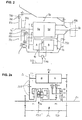
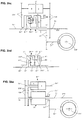
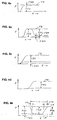
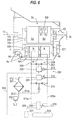
- Figure 1 shows the basic circuit diagram of a stepless, especially hydrostatic Power split transmission with several shift ranges.
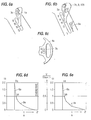
- a transmission scheme one such a transmission is shown in Figure 3.
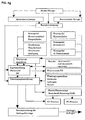
- the transmission adjustment is one of two or more Operating signals, in particular engine speed signal b and accelerator pedal signal or engine control signal a or throttle valve angle DW resulting signal c and / or via a So-called EP adjustment, according to Figure 8, with two input signals C1 and C2 for adjustment of the hydrostatic transmission possible.
- C1 and C2 are electrical quantities based on an electrical one Adjustment with proportional solenoids and in proportion to the adjustment variable of the hydrostatic system.
- the accelerator pedal signal a can be a throttle valve adjustment signal or also as an engine control signal k, which is connected to the engine via the control unit 5, serve, the signal k is identical to the accelerator pedal signal or a modulated variable, depending on certain Operating parameters.
- the accelerator pedal is therefore preferably to be understood as an accelerator pedal.
- the invention further relates to a motor vehicle transmission, in particular with Power split, which consists of a stepless converter 4c, according to Figure 2; 3; 3.1; 4; 5, preferably a hydrostatic converter, which consists of a first and a second hydrostatic unit there, both units preferably forming a common structural unit and drive or / and Output of the stepless converter 4c, depending on the embodiment, via direct drive or via intermediate drive wheels.
- the input is divided into two on the input side Power branches, whereby a power branch flows over the stepless converter and before Transmission output again, if necessary, in a summation transmission 5c with the other Power branch is summed up.
- Power split transmissions consist of one or several switching ranges.
- Switching from one area to the other is preferably done at each end adjustment point of the hydrostatic unit, with the Adjustment variable remains unchanged, with the exception of any minor adjustment corrections.
- the Hydrostat four times over the entire transmission range from an adjustment maximum to drive through another adjustment maximum. 3 is in the start-up state at closed clutches K5 and KV and after closing clutch 1 the hydrostatic on its maximum negative adjustment variable set.
- the hydrostat is now used for starting pivoted back to "zero" and beyond to his other understanding, positive Adjustment maximum where at the end of the first and at the beginning of the second switching range Synchronous operation of all clutch elements in the second area by closing clutch K2 and Opening the clutch K1 the second area is switched.
- the summation gear is here as multi-shaft Planetary gear P1 designed, in which the mechanical and hydraulic power adds up becomes.
- the mechanical and hydraulic power flows in the first and in the second switching range via the second planetary gear P2 with clutch KV closed.
- the first and the second shift range is made possible by closing the clutch KR by the direction of rotation in planetary gear P2 is reversed.
- the adjustment maximum of the hydrostatic mentioned in each case defines the point at which the Switching takes place in the next driving range, which is not necessarily the understanding of the Hydrostat must be, but can also be something in front, for example, depending on the load Compensate slip of the hydrostatic transmission.
- the synchronous operation is also too Closing clutch elements not absolute synchronous operation but the synchronous operation range defined, which may include wanted or unwanted synchronism errors caused by the Switching or range clutches can be bridged or still accommodated.
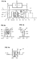
- the transmission versions like. 2a and 3.1 are functionally identical to the described transmission design according to. Fig. 3. They differ essentially in the fact that the respective summation planetary gear in the embodiment of FIGS. 2a and 3.1 is arranged coaxially to the drive shaft 1c, which is why an additional planetary gear set is connected upstream in the summation planetary gear. If you like execution.
- Fig. 2a is also the output shaft 2c coaxial to the drive shaft, while according to execution.
- Fig. 3.1 the output shaft 2c axially offset from the drive shaft 1c by means of a spur gear stage 2d lies. If you like execution. 3.1, an intermediate shaft (73c1, as required in FIG.
- a PTO or PTO shaft connection 2e for example for the tractor, can be realized in an advantageous coaxial position to the drive shaft 1c.
- the third output shaft A3 is not an inner but an outer shaft and is located above the clutches K1 and K2.
- a drive connection is made via the web shaft of P3 with clutch K4 already closed and a spur gear stage 2d to the output shaft 2c.
- Gearboxes of this type are according to DE 40 27 724, DE 41 06 746, EP 0 386 214, US 5,267,911 with part of this invention are described in more detail.
- the invention provides, inter alia, one Improved design of this known transmission and the invention according to DE-A 44 17 335; EP 0599 263. The description of the latter two documents are part of this Patent application and serve to explain details in more detail.
- the invention provides, inter alia, one or several hydrostatic powerless operating points, especially fixed translation points realize.
- the hydrostat at one or more operating points are located in main operating areas, in particular, by appropriately trained facilities switched off or bridged to put it in a de-energized state. This shutdown or
- Bridging device is in the form of a hydrostatic locking device KH or / and an area block circuit and / or a stabilization device KD with or without Direct drive through realized without hydrostatic power.
- the transmission is equipped with a braking device, which in Active connection with the hydrostatic bypass device or translation fixed-point circuit and the stepless converter 4c stands, as partially in DE 44 17 135 A1 described.
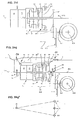
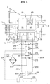
- FIG. 4 shows an example of a power split transmission with a hydrostatic one Converter 4c and a summation gear 5c shown.
- the summation gear 5c can also have the function of a branching transmission, which is why the designation below "Summation / branching gear" is used.
- the hydrostatic converter consists of a first hydrostatic unit A adjustable volume and a second hydrostatic unit B preferably constant volume. Both hydrostatic units A and B preferably form one common structural unit, which directly or via drive wheels with the drive shaft 1c and on the opposite side directly via additional drive wheels with a summation gear 5c in Drive connection is established.
- the summation gear is preferably a planetary gear designed, depending on the version, a further gear 5d, with or without switching devices, e.g.
- the Power is divided on the input side into a hydrostatic and one mechanical branch.
- the hydrostatic power share flows through the drive wheels and Intermediate links 227 via the stepless converter 4c and the drive wheels on the Summation gear 5c.
- the mechanical branch is directly or via intermediate links in the Summation gear 5c guided by hydraulic and mechanical power flows be added together and reach the output shaft 2c together.
- the stepless converter or the hydrostatic transmission 4c is in this case with a hydrostatic bypass device Hydrostatic locking device in the form of a brake or clutch KH, which is used to hold the drive shaft 7c of the second hydrostatic unit B or with the housing 19c of the stepless converter or a fixed gear part to couple, so that at Power split transmission known support moments via the clutch or Brake is preferably supported on the gearbox or converter housing in order to Relieve the hydrostatic transmission or keep it torque-free and pressure-free. It is also possible, the hydrostatic shaft 7c of the hydrostatic unit B by another, not shown Separate clutch completely.
- the hydrostatic locking device KH has the task of the stepless converter 4c or the Hydrostatic transmission in the hydraulically inoperative operating states with hydrostatic variable To keep "zero" torque or load-free. This is solved in such a way that the Torque support force from the summing / branching gear 5c with hydrostatic zero position, which is usually in the middle of each switching range, not at the Hydrostat elements but on a corresponding intermediate brake or Coupling element is supported in relation to a fixed housing part or gear part.
- the hydrostatic transmission is inside several times drive through its full setting range, the within each switching range Hydraulically inoperative state with neutral position, that is, with variable "zero" of the Hydrostatic transmission, corresponding to the hydrostatic neutral position. This operating point is mostly in an important operating area of the vehicle, in which a particularly good one Efficiency is required.
- a bypass valve 114c is provided, which is between the two working pressure lines of the two hydrostatic units A and B is switched.
- This bypass valve is automatic or too can be operated manually with the hydrostatic locking device switched, which means both Working pressure lines are depressurized or without differential pressure.
- the hydrostatic locking device or the clutch / brake KH and the bypass valve are usefully over the same Control pressure controlled, but the bypass valve only after the clutch / brake is closed KH is activated such that the pressure feedback after the clutch KH closes the signal or triggers the control pressure to activate the bypass valve.
- the hydrostatic locking device KH can be switched automatically or manually, e.g. B.
- the gearbox in the hydrostatic neutral position or in the vicinity of e.g. maximum 8% of current translation with a pre-programmed time variable for this dwell time, e.g. 2 seconds, triggers the corresponding control signal for the hydrostatic locking device, such that a largely seamless continuous adaptation of the corresponding translation and the Engine speed to the desired speed.
- this operating state and the driver via an optical or acoustic signal Show switching option preferably this operating state and the driver via an optical or acoustic signal Show switching option.
- the hydrostatic lock can also be released in various ways take place, e.g. by a drive or accelerator pedal signal, that is when the Accelerator pedal position or by a load-dependent signal or by various signals through variable operating values can be determined.
- the driving control should be designed so that the transmission efficiency line and the engine’s best fuel consumption line and the Vehicle control depending on the respective operating situation decides whether the nearest gear ratio point with hydrostatic neutral position to be controlled or not.
- a further parameter depending on the load or Noise behavior of the gearbox also saved as a decision factor or be programmed. This can be useful, for example, when used in a car.
- the invention further provides for the hydraulic power branch also to the Switch off translation points of the area switching points. That means that at the end of the old one Switching range and at the beginning of the new switching range, the couplings KB for both areas remain closed and the hydrostat is fixed in this adjustment size and set without load, e.g. B. by simultaneously operating the above-mentioned bypass valve or / and an exact one Alignment or correction of the hydrostatic adjustment such that the two hydrostatic Working pressure lines are depressurized or without differential pressure.
- the performance is in this Switching state is transferred purely mechanically via the clutches or Coupling devices of the two adjacent or adjacent switching areas.
- the Switching signals for this circuit can be given the same signals as for the hydrostatic locking device KH described, can be realized.
- a transmission e.g. B. with four Forward travel ranges, as shown in FIG. 3, are seven fixed translation points in this way switchable with no load hydrostat.
- the invention provides a power split transmission Stabilization device KD or hydrostatic bridging device in front of one or several translation points holds fixed translation settings at which the Hydrostatic power flow can be switched off to further improve efficiency.
- z. B. the output shaft 2c via a gear 10b with Drive shaft 1c via an intermediate shaft 227 by engaging a clutch KD in Drive connection to put the hydrostatic transmission without load after this clutch is closed.
- translation stages provided with a correspondingly assigned clutch will.
- An embodiment according to Figure 3 shows e.g. a stabilization or hydrostat bridging device, in which a direct drive through without a KD clutch Tooth meshing or tooth rolling power, produced between the input shaft 1c and the output shaft 2c and thus the converter 4c and the summation branching gear 5c in the no-load state is set.
- the stabilization device or hydrostatic bridging device KD is also included two or more clutches executable (not shown) to the stepless converter and to decouple the summation branching gear completely.
- the second clutch can be dispensed with.
- the invention provides an improvement in the device according to the German published application DE 41 04 167, claim 17.
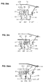
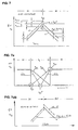
- the purpose of preventing switching off in the switching range of two adjacent range switches is Fixed point circuit KB described by closing both area clutches, e.g. K1 and K2, as shown in Figure 7b corresponding to the operating phase Ph 2.
- the Operating variable from a differential value of the hydrostatic adjustment volume ⁇ V or ⁇ nHy or / and a difference value for the load signal ⁇ p or / and a preprogrammed time difference signal or other signals can be.
- the corresponding signal sizes mentioned above can preprogrammed and depending on various operating values, such as operating temperature, Accelerator pedal signal or others can also be influenced.
- the functional sequence is such that as shown in Figure 7b, near the translation fixed point KB with the same Driving speed or output speed Nab an automatic increase in Output speed nHy of the second hydrostatic unit B with a corresponding one
- the engine speed nMot is reduced by the difference value delta nMot.
- Figure 7b can e.g. in the first operating phase Ph1 the first range clutch K1 and at Fixed point circuit according to operating phase Ph2, the clutch K1 and K2 must be closed and in In the third operating phase Ph3, the clutch K1 is again closed and the clutch K2 open.
- the difference values delta nHy or delta nMot for the drive motor can be in any size or in any ratio and depending on the vehicle type different sizes e.g. 5% to 10% of the respective reference size.
- the engine speed variable nMot smaller is as the hydrostatic speed variable nHy or in a relation, not shown, the speeds to each other, that in the phase of the fixed point circuit Ph2 the engine speed nMot rotates synchronously with the hydrostatic speed nHy .., as with the concerned Planetary gear members HMot and sHy of the gearbox according to FIG. 3 in the fixed point circuit K1 / K2 would be the case through block rotation of the summation planetary gear P1.
- the clutch for the hydrostatic bridging devices KH; KB; KD is Executable in various ways and can be used, for example, for the hydrostatic locking device KH arbitrarily on one of the intermediate links or drive elements 7c between the second Hydrostatic unit B and the summation gear 5c can be arranged.
- the KH couplings; KB; KD are preferably designed as a positive coupling as in PCT publication DE-A-87/00 324, DE-A-41 26 650 A1 and in European PCT application DE 88/00 563, which Part of this invention are described in more detail.
- the clutch stands out in particular characterized in that they have positively switchable coupling elements with coupling teeth with or without deflection teeth and that by means of a clutch carrier displaceably arranged hydraulically actuated piston the circuit with synchronous operation or in the synchronous operation range is also possible at a certain relative speed. It is also possible, as in described above known publications, additional synchronizers to provide.
- This aforementioned positive coupling has the advantage that it is almost is drag-free since there are no friction elements.
- Clutch as a friction clutch in the form of a cone clutch, such as. B. in DE-A-41 26 650 illustrated to use. This coupling can also be largely free of drag loss as a result of the cone effect the friction surface is relatively small.
- a multi-plate clutch in well-known construction can possibly be designed sensibly.
- Another kind of one positive coupling with mechanical switching elements e.g. B. by means of switching claw, Shift sleeve and / or with servo-reinforced switching elements, depending on the selected Gearbox construction, sensibly applicable.
- the clutch KH is alternatively in a form not shown arranged for the hydrostatic locking device in the summation gear 5c.
- traction booster 77c and clutch KH can a common structural unit can be summarized in terms of space and cost.
- the hydrostat is in all previously described devices for switching off the Hydrostatic operation via the bypass valve 114c described; 216 or / and by a corresponding trained hydrostatic adjustment control to be set without load.
- the hydrostatic transmission is based on the theoretical Adjustment volume size Vth adjusted or adjusted so that no differential oil quantity is exchanged between the working pressure lines 206, 207 when the bypass valve is open or the working pressure lines without the bypass valve 114c, 216 switched or without the bypass valve 206, 207 are almost free of differential pressure.
- the hydrostatic transmission will open in this case differential pressure-free state regulated by various control methods, one method is controlled via the respective differential pressure quantity in such a way that the differential pressure is a Adjustment signal on the hydrostatic transmission triggers, so that a constant adjustment automatically causes at least approximately differential pressure-free state of the hydrostatic transmission.
- the hydrostat adjustment itself continuously a new adjustment variable corresponding to a displacement volume size Vneu adjust depending on the drive torque or according to the respective changing load condition of the engine and transmission varies so that when leaving the Fixed point switching, i.e. at the start of the new circuit or range switch, the right one immediately Adjustment variable or displacement volume variable Vneu is available, the torque-free Condition of the old clutch K1; K2 or clutch KH; KD and the cheapest adjustment size Vnew for the opening signal of the corresponding clutch with almost no torque Condition corresponds.
- the switching sequence for leaving the fixed point circuit and switching in The new stepless shift range is according to the invention in this shift variant accomplished that with automatic torque-dependent constant adjustment of the adjustment on Adjustment variable Vnew takes place in such a way that the bypass valve closes first and then the Opening signal for the old clutch when the relevant torque-free state Coupling member is initiated.
- the bypass valve 114c, 216 is closed, e.g. when shifting from KB to the stepless range, the full torque to the new one Clutch K1 or K2 relocated and the old clutch set torque-free if correct Vneu and open.
- stepless switching range When switching from the fixed point circuit KH or KD to Subsequent stepless switching range is the first by closing the bypass valve relevant clutch KH; KD relieved of the torque and then opened by a corresponding opening signal.
- the bypass valve 114c, 216 is used to optimize the switching quality alternatively designed so that a continuous but nevertheless rapid pressure build-up when Closing process is guaranteed.
- the continuous build-up of pressure can be of various types have a characteristic course and, for example, correspond to a fixed specification by known means such as throttle damping, damping grooves, etc. or depending on one or several operating values, in particular load-dependent values, e.g. through the hydrostatic pressure vary. Electrical-electronic controls can also be useful for a seamless Switching sequence, especially in connection with the described hydrostatic retarder.
- new clutch in the fixed-point circuit KB is the clutch K1 or K2 loaded after leaving the fixed-point circuit and with old clutch understand the clutch K1 or K2 to be relieved of the torque and then opened. Both clutches K1 and K2 are loaded with torque within the fixed point circuit KB.
- the functional sequence of the retarder brake system which is described in more detail in DE 44 17 335 A1, is as follows: As already described, when the brake is applied, the closest or cheapest translation fixed point is achieved by automatically adjusting or increasing the engine speed Simultaneous gear ratio reset adjusted and switched, whereby the hydrostatic transmission is initially in a no-load or depressurized state. For example, when the ratio is fixed via the range block circuit KB, the hydrostatic unit A is generally swung out fully in this state, as a result of which both hydrostatic units keep the corresponding amount of oil in circulation at the same speed without differential pressure within the converter transmission.
- the adjustment unit A Only after the fixed gear ratio has been switched and after the hydrostatic unit A has been adjusted to a smaller volume is the differential oil quantity fed into the brake pressure circuit 206 or 207 and braking power generated when the pressure valve 204 is set or regulated to the appropriate pressure. If the adjustment unit A is adjusted to the adjustment variable "zero", the total amount of oil, which is generated by the second hydrostatic unit B, which is generally designed as a constant unit, is fed into the brake working pressure circuit 206; 207 pumped . If the hydrostatic adjustment is continued by "zero" and beyond, the adjustment unit A also works as a pump, delivering the same pump output and braking power as the constant unit B at the end of its adjustment variable, that is to say with a full adjustment volume.
- both hydrostatic units A and B can also be designed in different sizes and both as adjusting units, the respective braking powers being different according to their size and their associated speed. If the second hydrostatic unit B is also designed as an adjustment unit, further variations are possible, for example in such a way that both units are adjusted simultaneously or first the unit B and then the unit A, depending on the operating situations, can be sensibly regulated in their adjustment variables. In the known transmission designs mentioned at the outset, it makes sense to design the second hydrostatic unit B as a constant unit.
- the service brake is first activated via the automatic brake control or the electronic braking system (EBS), so that a largely no-load is activated when the engine speed is increased at the same time Condition in the hydrostatic transmission with simultaneous automatic adjustment of the hydrostatic unit A is carried out.
- EBS electronic braking system
- the braking effect of the service brake BB increases continuously.
- the hydrostatic transmission is now brought into the corresponding end position or final variable with simultaneous, corresponding engine speed adjustment, after which the service brake immediately after completion of the switching of the above-mentioned translation fixed point while simultaneously taking over the hydrostatic braking power is continuously relieved by adjusting the hydrostatic transmission the service brake.
- This functional sequence can be implemented according to a predetermined program in the EBS by means of appropriate computing processes and processing the signal variables from several operating variables such as brake pressure signal, hydrostatic pressure signal, adjustment signal of the hydrostatic transmission and / or engine speed signal and / or further signals.
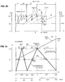
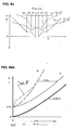
- 2b shows the engine speed behavior in various braking situations, for example for braking operation at 80 km / h.
- the speed point of the motor PB4 is based on an application example for a bus at a speed of approximately 1270 rpm.
- the fixed point switching takes place by engaging the corresponding clutch KH (see Fig.
- the brake control BR or the BRS is preferably programmed here so that this operating point is avoided, so that an automatic speed reduction from 80 to, for example, 68 km / h is effective in order to excessive engine speeds, especially for acoustic reasons and excessive oil temperatures and excessive stress to avoid the components. If the speed is reduced from 80 to 68 km / h, for example, the fixed-point circuit KB can be activated at a maximum speed of 2000 rpm.
- the same functional sequence described above can also take place in the reverse order and mode of operation, as already mentioned above, when transitioning into the flatter roadway level.
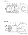
- the hydrostatic braking device BH exists in addition to the hydrostatic converter 4c from a first check valve 209, via which the oil flow of the respective High-pressure line 206 or 207 to a switching valve 203 and a downstream pressure control valve 204 is directed.
- the switching valve 203 is an opening signal 214 to release the hydrostatic brake function switched, whereby the flow to the brake pressure control valve 204th is released.
- the pressure control valve 204 is controlled via a variable control signal 215, that depends on the size of the hydrostatic braking force and the hydrostatic pressure certainly.
- the heat exchanger 205 is arranged downstream of the pressure control valve 204, which has a corresponding line 217 receives the heated oil flowing from the pressure control valve and the cooled liquid via a further line 213 and a corresponding check valve 210 reintroduces into the working pressure circuit of the brake system.
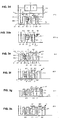
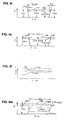
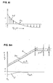
- the brake control RB provides various control strategies that can be installed alternatively or can be pre-selected as required. As shown in FIGS. 4a to 4e and in the functional diagram in FIG. 4f, the hydrostatic brake component FBH can be switched on at will to adjust the Service brake force FBB to reduce as desired.
- Figure 4a shows the braking force curve at a Braking operation in which the hydrostatic brake with the braking force during the braking phase FBH is switched on and the service braking force FBB in accordance with this force is reduced.
- the braking force of the service brake can, depending on the design of the brake control are reduced to zero so that the service brake, in particular for continuous braking operation BB is completely relieved.
- the automatic retarder activation takes place according to the Invention according to a preprogrammed time parameter that a continuous course of allows hydrostatic braking force FBH, the total braking force depending on FB the actuating force remains largely unchanged.
- a Embodiment provides that a corresponding control valve, not shown, or a comparable, not shown electronic, mechanical, hydraulic or other suitable device in which two signal quantities, namely those from the actuating force or from a set value resulting signal size and the hydrostatic brake BH resulting signal size SBH cooperate so that the control signal SBB for Service brake reduced or even to zero according to the hydrostatic signal size SBH is set.
- the hydrostatic retarder BH is controlled via the control signal SHY. At a sudden failure of the connected hydrostatic retarder BH, e.g. due to oil line break i.a.
- the control signal for the hydrostatic retarder preferably results from functions of the service brake or are a follow-up function from the Service brake system, which ensures adequate security according to the requirement of a independent service brake is given.
- the brake signal or feedback signal SBH off the hydrostatic retarder can be selected from the hydrostatic adjustment signals, the hydrostatic adjustment variable, the hydrostatic pressure and / or other sizes result which is a measure of the braking force FBH from the hydrostatic ratarder BH; 4c.
- the brake system can also be used different distribution ratios of the braking forces from the service brake BB or Hydrostatic retarder brake BH can be designed.
- For longer braking processes Depending on the braking time and / or the braking force size, a targeted activation of the Hydrostatic retarder brake with a meaningfully adjusted proportion ratio in various ways executable characteristics are preprogrammed. The most favorable values can can be determined experimentally depending on the vehicle type and other conditions.
- a cruise control device or constant speed control Depending on the road profile can it may be necessary, at the desired constant speed, that different Translation points can be adjusted automatically, especially when each braking force is applied different engine braking force proportion and correspondingly different engine speeds assigned.
- the service brake BB first has the full braking force FBB take over and according to a predetermined variable or constant time parameter or other, the hydrostatic brake or hydrostatic braking force depending on certain operating factors FBH can be added with (or without) simultaneous support from Engine braking effect through appropriate engine braking torque or engine braking force FBM Optimal coordination of the respective braking force components FBH, FBB and FBM can be determined experimentally depending on different operating situations.
- the in Fig. 4a 4b and 4b represent different braking operating situations that arise can be based on the same brake control strategy.
- a manually operated retarder circuit e.g. by an electric brake step switch or continuously variable switch is switchable.
- This device can be used as an additional permanent brake or for a simplified one Equipment in which the hydrostatic retarder serves as a permanent brake can be used sensibly, the respective activation of the continuous brake after a predetermined during the journey Fixed translation and switched fixed point circuit can be switched on manually.
- the in Fig. 4e The illustrated braking force illustration shows the short-term decrease in the hydrostatic braking force FBH , e.g. within a switching phase when changing from one fixed translation point to another. The hydrostatic braking force is reduced within the switching time ts, the Total braking force FBB is maintained through appropriate assistance and activation the service braking force FBB.
- the continuous braking force curve About the switching phase mentioned, as shown in Fig. 4e, according to the invention ensured when using the brake control device described and shown in Fig. 4f.
- the braking force curve within the described Umshaltphase from one to the another fixed gear ratio can also be useful with the help of the FBM engine braking force will be realized.
- the actuating force FF can be within the entire switching phase remain unchanged or can be changed as required, with a corresponding to the change analogous adjustment of the braking force FB takes place as it corresponds to the driver's request.
- the hydrostatic retarder BH In order to ensure the safe functioning of the anti-lock braking system (ABS system), the hydrostatic retarder BH must be switched off as spontaneously as possible during braking, while almost the entire braking force is taken over by the service brake, since the functions of the ABS system are based on service brake equipment. According to the invention, as shown in FIGS. 4i and 4k, the hydrostatic retarder BH is automatically switched off when the ABS system is activated via the electronic brake control RB. A corresponding signal S-ABS from the ABS control R-ABS (see FIG.
- the transition from retarder brake operation to ABS brake operation takes place largely continuously, as shown in FIGS. 4i and 4k.
- the total braking force FB is reduced to FB when the ABS function is activated or FB-ABS lowered according to the different friction coefficients on the braked wheels in question, as is the case with conventional brake systems without retarders.
- the motor brake force FBM with or without a lowering of the engine speed is reduced, which can be preprogrammed accordingly in the brake control and / or transmission control, as shown in FIG. 4k.
- the invention provides that the engine speed is initially maintained after triggering the ABS function in accordance with the previously given engine braking torque in order to maintain a continuous engine speed behavior with frequently changing function changes between ABS and normal braking operation or the aforementioned mixed braking operation or that According to a predefined characteristic, there is a continuous drop in engine speed, which is preferably to be determined experimentally and is to be determined and programmed on the basis of various parameters such as noise behavior, comfort and others.
- the hydrostatic retarder brake function can according to the invention for both Normal braking operation as well as continuous braking operation can be used sensibly.
- Normal braking operation the braking functions described are preferred over a Foot brake pedal triggered depending on the braking force and / or the brake pedal travel.
- the lever position preferably representing a measure of the braking force.
- the service brake BB is activated or the driver forced to set a lower driving speed by braking over the Foot brake or the service brake so that the brake system is prevented from being overloaded.
- the decisive factor for the limitation is primarily the oil temperature or the maximum possible Cooling capacity, e.g. via a temperature signal, which the driver or the brake control the limit of the braking power is signaled and if necessary to reduce the Braking speed forces.
- a corresponding acoustic or optical signal e.g. Flashing light on, prompts the driver to reduce the speed by braking on.
- Automatic speed reduction through automatic use of the Service brake and assistance from the service brake force FBB can be provided by appropriate Control function in the brake and transmission control an adapted driving speed. Cause reduction.
- the speed reduction in the aforementioned case by interim use of the service brake is specified according to the invention such that at service brake is switched off again at the new braking speed
- the Braking speed is reduced so far that the full braking force again over the Retarder brake system and the engine braking effect can be covered.
- the automatic The service brake is used in brake systems with hydraulic and / or pneumatic Energy supply (see Fig. 4g) by a corresponding control signal from the brake control RB realizable.
- the brake actuation can be done in various ways via the master brake cylinder, brake valve, electrical potentiometer, handbrake, retarder selector lever, etc., depending on the vehicle type and the Requirements.
- 4g shows the structure of a brake system e.g. for a Towing vehicle shown.
- the retarder braking system is designed as a hydrostatic retarder ABS suitability (see Fig. 4m and Fig. 4i, 4k, 4l, 4q).
- FBH hydrostatic retarder braking force
- FIG. 4q a signal S-ABS dependent on the ABS control, a corresponding reduction in the hydrostatic pressure caused in the brake circuit 206, 207 of the retarder, in particular by appropriate Influencing the brake pressure valve 204 by the corresponding change in the control signal 215 or / and the hydrostatic adjustment.
- Maintaining the total braking force as unchanged as possible is achieved by lowering the hydrostatic retarder brake pressure in the brake circuit 206, 207 or reduction in the hydrostatic braking force FBH causes a simultaneous, appropriately adapted increase in the service brake force FBB by appropriate control after triggering the control signal SBB Service brake system, as shown in Fig. 4m and 4q.
- electronics automatically compare and adjust the signal sizes SBH and SBB. which results in the total braking signal or the total braking force.
- the brake control system is like this designed that the signal size for the retarder braking force when using the ABS function of the Service brake signal SBB is pushed back by the appropriate amount or that as Subsequent function from the ABS function, the retarder braking force FBH is reduced accordingly, to maintain the independence of the service brake.
- the total braking force remains largely unchanged or, in the worst case, is only lowered as far as it is Allow road conditions optimally.
- the first Hydrostatic brake component FBH almost reduced to zero with a corresponding increase the service braking force FBB, which also includes the ABS function.
- the size of the ABS effect i.e.
- the Brake electronics decide whether and to what extent within the ABS braking phase Hydrostatic retarder brake can be switched on. As shown in Fig. 4q, depending on Given the slip conditions, a more or less large increase in the retarder braking force FBH from the information of the respective slip conditions on the braked Wheels via the relevant control signals for the retarder and service brakes to be triggered. This functional sequence contributes significantly to the service brake share and to reduce brake wear to a minimum.
- the brake system is for safety reasons designed so that if the hydrostatic brake system fails, the service brake immediately previous hydrostatic braking force takes over, with the corresponding service brake signal SBB takes effect on the service brake.
- the means for processing and transferring the mentioned signals can be known electronic, electrical and / or hydraulic-mechanical Facilities and elements.
- the invention provides that depending on the oil temperature and the temperature signal ST a corresponding adjustment of the hydrostatic retarder braking power is adjusted, with the Maintaining the necessary safety according to the permissible oil temperature Reduction of the driving speed by means of a translation reset is preferred automatically takes place and / or a corresponding acoustic or optical signal display to the driver Reduction in driving speed, e.g. by appropriate braking on the Foot brake actuation.
- the temperature signal ST is one of the decisive safety signals here.
- the invention also has a device as Cruise control , which in braking mode when using the hydrostatic retarder as a permanent brake causes the desired speed to be maintained via the actuating device, which can be implemented in various ways, e.g. as a brake switch, brake lever, keyboard or that the desired speed is set via the brake pedal and this brake speed after releasing the brake pedal is automatically held until the driver requests a change in speed by applying the brakes again or pressing the accelerator or accelerator pedal.
- the stored speed is preferably switched off or changed according to a continuous course which, depending on the driver's request and depending on the speed of change of the accelerator pedal, triggers a more or less rapid change in speed according to a predetermined program.
- a temperature signal ST ensures that the retarder braking power is reduced accordingly by automatically lowering the driving speed, e.g. by reducing the gear ratio or / and automatic takeover of part of the braking power by the service brake through a similar functional sequence as described above.
- hydrostatic retarder All of the functions described above for the hydrostatic retarder, also with ABS compatibility, can also be used for gearboxes of various types with assigned hydrostatic retarder known type, e.g. to replace the function of a hydrodynamic secondary retarder.
- This hydrostatic retarder is usually via a spur gear stage with the transmission output shaft connected.
- the hydrostatic circuit is designed so that on the low pressure side Oil inflow and on the high pressure side of the oil outflow and between high and Low pressure side, a preferably controllable pressure valve, which is effective as a brake valve, switched is.
- the hydrostatic unit can be used as an adjustment unit or as a constant unit high circulation oil quantities when the unit is not switched on Retarder function leads to unnecessary performance losses.
- Accelerator pedal or the accelerator pedal position or the cruise control device also the speed determined in braking operation without actuating the brake pedal or other actuation devices.
- the transmission output speed signal d ensures the maintenance of Target speed.
- An engine speed signal b determines the engine braking power.
- the Engine braking power can be dependent or independent of the total braking power that occurs a constant maximum size or a variable size, e.g. in Fig. 4n shown, take. 4n is for a certain operating state when driving varying gradient for a preselected constant speed the total braking force required FB shown.
- the engine speed nMot increased accordingly, which e.g. through the speed signal b to a automatic reduction of the gear ratio 1 / i and simultaneous increase of the FBM engine braking force and simultaneous automatic adjustment of the hydrostatic or Retarder braking force FBH leads. It makes sense, especially for acoustic and acoustic reasons Lifespan of the entire brake system, the engine brake share in a certain customized Pre-program the ratio to the total braking force FB, with a permissible maximum value for the engine braking force FBM and in particular the engine speed nMot is predetermined.
- the invention provides that regardless of the set speed value automatic speed reduction is activated.
- the signals for this can come from a or several operating signals such as temperature signal Sth, hydrostatic pressure signal or / and other signals that affect load or safety are triggered.
- the speed curve described in the retarder braking mode corresponds to the Representations Fig. 41 and 4o of the ideal line, i.e. a line with an infinite number of fixed translation points. Having a limited number of translation benchmarks, however, as already described, exists at the area limits of two adjacent switching areas according to fixed translation point KB, at the point of hydrostatic standstill at fixed point KH and, if applicable, at a further fixed translation point KD, is only a gradual one
- the engine speed can be changed as shown in Fig. 4p. That means one Corresponding gradual change in the gear ratio 1 / i must take place, the above. Ideal line or better preferred line can serve as a given guideline for orientation when switching to the next fixed translation point is to take place.
- Fig. 2b e.g. the maximum possible engine speed points PnMot specified. in the Speed plan Fig.2c is the hydrostatic speed curve nHydrostat, the drive speed nAn and the output speed nAb are shown in relation to constant travel.
- the each Possible fixed translation points KB, KH and KD can be seen in the speed plan.
- FBM engine braking force
- Fig. 4n calculated in the brake control device or in the electronic brake system (EBS) and decided depending on one or more operating parameters or values which one Fixed translation point is most suitable for the current braking condition.
- the brake system can be designed in various ways and can, depending on Vehicle type, e.g. with electro-pneumatic brake control with upstream electronic Control and the like can be executed.
- the control device can also e.g. with a driving dynamics control (FDR) can be combined or expanded.
- FDR driving dynamics control
- the means of realizing the described functional sequences of the individual control and Control devices are known elements or components of electrical, electronic electro-pneumatic, hydraulic or / and mechanical or other type.
- Sensors e.g. as speed sensor, adjustment angle or displacement sensor of the hydrostatic transmission, Pressure sensors, temperature sensor, ABS sensor etc.
- the function of each Signal processing is of a known type and is not or only partially in its details described.
- the invention provides, as in FIG. 4 indicated, the brake valve block 201 'with the hydrostatic transmission or the hydrostatic retarder 4c to connect or block directly, the hydrostatic transmission 4c itself over noise and vibration-reducing elements is mounted relative to the main housing 1.
- the noise isolating Hydrostat storage is particularly in the publications DE 42 35 728 and DE 43 00 456 described in detail.
- Control block which among other things the solenoid valves for clutch control and other details includes, is preferably fixedly connected to the main housing 1, the connecting lines to the hydrostatic transmission 4c and the brake valve block 201 'via known plug connections he follows.
- the oil cooler 205 ' is also connected to the brake valve block 201' via plug connections 202 '. connected.
- the connectors mentioned for the corresponding oil guides have the connection points noise and vibration reducing sealing elements.
- a hydrodynamic converter inform of a secondary retarder or Primary retarders applicable. Both hydrodynamic retarder designs are gem. of the Invention can be activated with the same or similar control elements or control signals.
- a Exemplary embodiment. 2 sees a hydrodynamic retarder 78 at the transmission input as the primary retarder.
- the rotor 81c of this retarder is connected to the drive shaft 1c.
- the stator 79 is fixed to the housing and is preferably accommodated in the gear cover 61c.
- This Retarder acts as a primary retarder, with the braking forces being directly dependent on the gear ratio stand so that even in the lower speed range in contrast to Secondary retarder the full braking effect is available.
- This retarder takes place via pneumatic and / or hydraulic valves, the control signals via the Electronics depending on one or more operating signals and the input values of the Driver are effective.
- This means, known per se, for executing the signals mentioned serve are not shown in the drawings.
- the hydrodynamic retarder (primary retarder 78; secondary retarder 83c) preferably as a continuous braking device and / or as brake support for the customary service braking operations designed, which is among other things the object of the invention.
- This The object is achieved in that the control signals for the control of the hydrodynamic Retarders 78; 83c are dependent on the actuation of the service brake, i.e. that at Pressing the brake pedal a simultaneous or staggered or subsequent, preferred dosed control of the hydrodynamic retarder takes place.
- This retarder control is in addition to the brake pedal signal also influenced by one or more operating parameters. Influencing variables are e.g.
- the invention provides for a minimum reduction in the retarder braking device - hydrostatic retarder or hydrodynamic retarder - to be equipped with a control and regulating device, which contains a predetermined program for the service braking, which provides that a automatic, preferably specifically metered activation of the retarder 78; 83c; 201, as above mentioned, causes.
- the braking program mentioned can be used here, e.g. in Fig.
- the hydrostatic retarder braking force FBH is the same as the hydrodynamic one Retarder braking force, but it must be distinguished that the hydrodynamic retarder at least in some functional processes it reacts more slowly depending on the filling time of the Blading.
- the hydrostatic retarder With the hydrostatic retarder, the activation and brake increase can be done faster take place than with the hydrodynamic retarder, since the braking force can be regulated spontaneously Hydrostatic pressure can be determined and not as with the hydrodynamic retarder Filling speed of the blading of this known brake system is dependent.
- the height Spontaneity and short response times of the hydrostatic retarder are a particular advantage i.a. compared to the hydrodynamic retarder.
- the automatic switch for the respective retarder system can also due to their characteristic differences can be programmed accordingly differently, the hydrostatic retarder also as pure service brake can act, especially when braking on one Fixed translation point or near a fixed translation point.
- the Brake pedal on the hydrostatic retarder causes a very fast hydrostatic adjustment or / and a corresponding hydrostatic pressure change via the relevant pressure control valve 114c; 204 (Fig. 2 or Fig. 4).
- the object of the invention is, inter alia, a switching device, preferably for automatic switchable gears, in particular for continuously variable branching gears of the type mentioned above positive clutches with or without deflection teeth or friction clutches with conical friction surfaces, as known from DE 41 62 650, or also with known multi-plate clutches create the high switching quality without interrupting the load.
- the leakage oil losses of the hydrostatic transmission cause, as mentioned at the beginning, an inevitable speed slip of a hydrostatic shaft 7c.
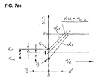
- This speed slip in conjunction with a continuously variable power split transmission with several driving ranges within the range shift, as shown in FIG. 7, has the effect that, for example, in train operation to achieve the synchronous state of the clutch members to be shifted, the variable V alt by the dimension X am Switching point must be greater than the theoretical value in order to reach the synchronizing point of the clutch elements to be switched at switching point S.
- the adjustment variable or the maximum adjustment volume is to be dimensioned correspondingly large when designing the gear unit.
- the speed slip Due to the mentioned function reversal from pump to motor and vice versa after switching to the next switching range, the speed slip also has the opposite effect, which corresponds to an adjustment correction quantity by the dimension Z and thus the adjustment variable V new, after which the torque changes from the old to the new Coupling has taken place and the opening signal for the old clutch is triggered.
- the correction variables X and Y have different variables, due to the respective transmission design and range variables corresponding to the different variables of the hydrostatic pressures ⁇ p1 and ⁇ p2 or ⁇ p old and ⁇ p new at the end of the old and the beginning of the new shift range.
- B1 means 1
- B2 means 2
- the functional sequence is described in more detail in the publications mentioned at the beginning.
- the adjustment correction is used to optimize switching Operating values of the drive motor M controlled / regulated. Determining the size of the Adjustment correction X; Y; Z is the respective or current drive torque Tan des Transmission or the engine torque Tmot.
- the closing process of the new clutch after the end of the old switching range takes place in the synchronous state as with all of the aforementioned solutions Coupling members of the new clutch, preferably two or more speed sensors by comparing the speeds of at least two transmission elements the synchronous state determine and trigger the switching pulse for the new clutch.
- the current drive torque of the gearbox or engine torque Tan determines the load size of the Hydrostatic transmission and the corresponding speed slip of the hydraulic motor / pump and thus also the size of the required adjustment correction within both closed Couplings.
- Each drive torque is therefore also a specific adjustment variable or Displacement Vneu assigned to the torque-free state of the old Coupling corresponds, after which the opening signal for this clutch is triggered.
- Torque changes within the shift phase, with both clutches closed are automatically taken into account in this correction device, since the current one is always Drive torque Tan or motor torque Tmot the opening signal of the old one Coupling determines or via corresponding, resulting signals to open the old one Clutch triggers. Regardless of whether it is a train upshift, train downshift, The system recognizes the overrun or overrun downshift cheapest opening point or the new adjustment volume Vneu to trigger the Opening signal of the old clutch.
- the system also recognizes the respective operating status by that the engine is toured accordingly at thrust torque and depending on the speed corresponding to signal b, a corresponding braking torque or negative engine torque or Thrust torque size is recognized and from the corresponding signal sizes b, a or Brake signal f torque magnitude Tmot; Tan and torque direction determined and from it the shift correction quantity and direction and Vneu to open the old clutch defines and signals.
- the correction values and are reversed Correction directions take place, the displacement or the manipulated variable when shifting up Valt is less than Vneu and when switching back, Valt is greater than Vneu. This corresponds to that general characteristic shift correction behavior in such hydrostatic-mechanical, but also purely mechanical power split transmissions.
- the speed slip variables of the Hydrostatic transmission before and after the range shift with the same input and output torque at each range switching point each be very different according to gearbox design and division of areas.
- the correction variable ratios X to Y are different. Accordingly, in tax and Control system the correction quantities or correction quantity ratios X to Y programmed, i.e. it is basically every drive torque for every range switching point a separate manipulated variable or displacement volume variable Vneu is assigned and preprogrammed, the load conditions and others that change depending on the switching phase Factors can be corrected so that there is no switching shock in all operating states Range switching is guaranteed.
- each for the determination of the engine torque suitable signal quantities in the cruise control or control and Control device programmed.
- RQ control of each throttle or Accelerator pedal position and given engine speed a certain engine torque assigned so that throttle or accelerator position signal and engine speed signal a Give information about the respective engine torque, according to which the new displacement or the variable Vneu is determined and the opening signal for the old clutch is initiated can be.
- RQV control each accelerator or accelerator pedal position corresponds to one specified engine speed size regardless of the engine torque. This type of regulation is it is therefore necessary to determine the engine torque, a corresponding signal that the Filling level of fuel injection or a similar signal size for the Torque determination is suitable to use.
- This correction variant is in contrast to the one described earlier Variant not required, the adjustment correction variable Z from a hydrostatic pressure signal or to determine or calculate a correction variable X or Valt given before the start of switching, but the opening signal can always from the currently effective drive torque Tmot or Tan can be determined.
- the correcting variable or Vneu is usually provided by an appropriate displacement sensor or sensor that detects the Adjustment angle or adjustment path of the hydrostatic transmission signals.
- Known Verstelltik- or electrical adjusting current size are used, provided that this for the Determination of the correct opening signal are suitable for the old coupling ..
- a pressure sensor for recording the respective hydrostatic pressure is in this correction variant not mandatory.
- Vneu can be the difference between Vtheoretical and Valt or one Program should be provided, which does not require the help of Vtheoretical by primarily from experimental determination, the corresponding Vneu is assigned to each Valt.
- the adjustment values of the hydrostatic transmission can be recorded via a potentiometer which is known per se and which defines the adjustment angle or the adjustment path, a proportional current determining the adjustment angle or the adjustment volume of the hydrostatic transmission or via a current quantity, which is also a measure of the Indicates the adjustment angle or the adjustment path of the hydrostatic transmission.
- the individual range clutches or clutches for the fixed-point circuit are expediently via known electromagnetic valves 61; 62; 63; 64 or via solenoid valves 64 designed with a non-return function controlled.
- a proportional valve 3 which can be implemented in various ways in a known manner, is primarily used for the hydrostatic control.
- a control sensor or displacement sensor with feedback in a known manner.
- at least two speed sensors Sa; Sb; Sc; SD; Se; Sf (see Fig. 8) is used.
- the speed sensors can be connected directly or indirectly, for example through interposed spur gear stages, or in active connection with the two hydrostatic units A and B.
- the transmission has several sensors as shown in Fig. 8. The transmission input speed is measured via the speed sensor Sc and the output speed via the sensor Sd, which are also used to determine the gear ratio given in all operating points.
- the sensors Sa and Sb or Sa and Sc are preferably suitable for determining the synchronous state or range of the range clutches to be switched.
- the other sensors Sf and Se show the respective speed of various transmission elements.
- the speed signals b for the input speed from the sensor Sc and the output speed signal d from the sensor Sd and the sensors for the transmission elements Sf and Se can be used.
- one or more of the replacement sensors mentioned automatically take effect to determine the respective synchronous state.
- the failure of a sensor is indicated to the driver optically and / or acoustically by a corresponding signal for immediate damage repair. Basically, only two sensors would be sufficient to fulfill the basic functions, the information, which area and the adjustment signal is required for determining the translation.
- the adjustment change mentioned can be a one-off or repeated upward and / or downward adjustment of the adjustment member within the synchronous range, which causes a corresponding change in the adjustment current or the adjustment signal of the hydrostatic transmission.
- a direct countermeasure in one and possibly subsequently in the other adjustment direction is generated by preferably impulsive adjustment impulses, whereby, depending on the type of execution and requirement, a Shaking effect can arise.
- a targeted functional sequence provides that this switching effect or this switching aid device is only activated after a pressure feedback of the pressure piston via a corresponding feedback line 57; 58; 59 has taken place in the control and regulating device 5.
- a further variant provides that the switching effect mentioned is triggered after a defined period of time, for example twenty milliseconds, after triggering the switch-on pulse for the new clutch and lasts for a fixed, in particular experimentally determined period of time.
- the specified time period can be a constant value or a value dependent on one or more operating values, for example the oil temperature.
- a single adjustment pulse in one adjustment direction which acts as an interference pulse in relation to the synchronous state, is sufficient.
- the optimal effectiveness of this switching function can be determined experimentally. After the functional sequence of this shifting aid expires when the clutch to be shifted is largely torque-free, there is no negative influence on the shifting quality.
- This shifting aid described above is particularly suitable for positive-locking clutches with or without deflection teeth as already described at the beginning and described in more detail in the documents DE-A-41 26 650 A1 and the PCT application DE 88/00 563.
- the brake signal f that is effective for the gear ratio feedback control can be dependent to the brake actuation force and / or to a greater or lesser extent depending on the engine speed stand, preferably in the lower speed range and starting range, e.g. at the When the brake is released, the amount of braking via the service brake can be very low or almost zero can.
- the brake signal f can therefore, depending on the type of vehicle, according to a specific one Brake characteristic a fixed or changeable to different operating parameters Represent characteristic curve.
- the brake signals 113; 217; 215 of the braking, control and regulating device for the Retarder brake system can advantageously indirectly or directly with the brake signal f in Be brought into operative connection or be effective as a brake signal f.
- An improvement of the range switching within the braking and / or overrun mode is achieved by the combination of the transmission-side braking via the influence of the Brake signal on the gear ratio and the interaction with the described Bypass valve.
- the engine speed is increased due to the influence of the brake signal the corresponding change in ratio of the transmission, which at the same time the spontaneity of the Switching sequences and the adjustment speeds is positively influenced because of higher speed Control pressures and control oil quantity, both for the hydrostatic adjustment and for the clutch switching elements is improved.
- an automatic filling or Throttle valve position signal and possibly other operating signals becomes one Harmonious, comfortable range switching, even in extreme braking and pushing situations achieved.
- the braking components are automatically via the normal service brake system and the transmission brake is metered in such a way that the transmission and service brakes interact is prevented by a correspondingly adjusted dosage of service brake and Transmission or retarder brake system is achieved through active connections of the aforementioned signals.
- the amount of engine braking is dosed so that the engine noise is acceptable remains held.
- the Engine braking power should be very low despite a relatively high braking force, meaningfully one appropriate engine speed control depending on the driving speed and / or the gear ratio and / or the brake size can be preprogrammed. It is therefore advantageous because at low speeds the amount of transmission braking to be supported by the engine is relatively large even at low engine speed due to the correspondingly large Gear ratio.
- the invention provides for an engine speed reduction with preferably continuous course with the vehicle deceleration or with falling Pre-program the travel speed within the braking mode.
- the invention further provides an improvement of the turning or shuttle operating device with an IFA pedal, as is known from the publications WO 96/02400, DE 195 42 993, DE 196 41 723 and others, which are part of this invention.
- the function of the IFA pedal can proceed in this improved or further alternative as follows: After releasing the IFA pedal, an engine control signal is automatically triggered to increase the engine speed, e.g. as in the speed line nMotIII acc. 8ab and 8ac. At the same time, a translation change is made to set the vehicle in motion.
- a predetermined driving speed v arises; or output speed nAb on.
- the engine speed nMot can be different in relation to the driving speed, as shown in FIG. 8ab.
- a constant engine speed can also be specified, whereby a differently sized engine charge is triggered according to the resistance.
- the engine speed is of different sizes, for example between two predetermined engine speed lines I and II.
- the driving power required at the respective driving speed which can vary in size depending on the operating conditions, is decisive for the respective engine speed.
- the IFA pedal is similar to an inverted accelerator pedal, with the pedal release travel s or / and the inverted pedal force F-IFA determining the size of the motor control signal.
- An additional influence of the motor control signal is the given driving resistance, which has an effect on an engine pressure and thus contributes to a further increase in the engine speed according to its size.
- a setpoint / actual value comparison of the output speed nAb is preferably used as the control function, from which the signal for raising or adapting the motor control signal is formed.
- the control device is programmed so that if the output speed nAb deviates from, for example, 5%, an adaptation of the motor control signal is triggered automatically to adapt the motor output accordingly.
- an adaptation of the motor control signal is triggered automatically to adapt the motor output accordingly.
- a more or less large deviation of the actual value line from the setpoint line of the output speed nAb or v can be specified for the adjustment control .
- the controlled variables NEEDED, NEEDED should preferably be determined experimentally, whereby a different relationship can be achieved via the IFA pedal travel s-IFA or the pedal force F-IFA.
- the braking device described above via the hydrostatic braking system can be advantageously controlled via the signals of the ABS system.
- An emerging slip signal or ABS signal can activate the bypass valve automatically during braking 114c; 216; or / and cause a reset of the hydrostatic adjustment, whereby automatically by the influence of this or these signals a no-load state or torque-free or a corresponding torque-reduced state is produced.
- the bypass valve 216 is adjusted to a correspondingly changed or reduced hydrostatic pressure.
- the braking force via the gearbox or the brake retarder or hydrostatic retarder can be used here correspond to the size of the ABS signal.
- the invention further provides for range switching for both up and down Downshift, pull or push shift in combination of the ones already described Shift correction or / and as an alternative to a shift correction device before, according to how in Fig. 7c, the switching correction quantity Z over an adjustment correction time tk is determined.
- the adjustment correction time tk determines at the time of switching or in the switching phase depending on the adjustment speed, the size of the correction value or path Z.
- the decisive factor here is the control flow or the delivery volume Qk.
- the effective one Control current Qk is determined by various variables such as Feed pump delivery volume, speed, control pressure (constant or variable), internal Throttling effects, oil temperature etc. determined or influenced.
- the size of the The adjustment speed or the adjustment current Qk can be determined experimentally in further dependency on the different operating states, - engine speed, engine control signals such as throttle valve position, accelerator pedal position, oil temperature etc. - from these
- the aforementioned values are recognized by the control device or the electronics as to which adjustment correction time in which operating state for determining the respective correction variable or the new one Displacement Vneu is required.
- the temperature in particular the oil temperature, oil viscosity and, if appropriate, others the volume flow of the adjustment devices, leakage oil changes and the switching time influencing factors are taken into account by appropriate signal processing in the Control device.
- the type and size of the load can be specified in the program, which means a corresponding adapted enlargement or change of the correction (Z; tk) is realized.
- control and regulating device or electronics furthermore an automatic change and adjustment of predetermined values, in particular depend on the operating time and / or type of application.
- the adjustment mentioned can be based on can be realized in various ways, e.g. such that malfunctions or malfunctions in the control device or electronics are recognized, from which e.g. one out of a bump resulting signal or interference signal causes a change in one or more predetermined sizes or fixed values takes place, so that despite changing operating values, e.g. the leakage oil quantity, the correction quantities tk; Z can be adjusted so that good switching quality is preserved or improved.
- Triggering signal for this correction or internal Correction of preferably predetermined or prevailing variables can be one, in particular Torque change occurring during the switching phase of an engine or Transmission link or a torque or speed changing signal or / and Rate of change and / or change in a mass force or generally a shock or jerk-indicating signal.
- a suitable signal variable for changing internal specifications or The engine speed signal in particular in the constant driving range, can be fixed values, whereby at a deceleration shock triggers an engine speed increase, which automatically causes a appropriately adjusted change of one or more of the internal default values or Fixed values and / or signal size is effected, so that in this case e.g. a corresponding Increasing the adjustment correction value tk or Z is achieved.
- signals can also be a signal that results from the Change in a mass force mentioned above results, for example, by the Mass change within the switching sequence a decision to shorten or Extension of the switching correction time tk or the adjustment correction variable Z is realized.
- the change in the internal fixed values essentially depends on the course of the operating time changing values, e.g. depending on the wear of individual elements or / and as a function of a strongly changing operating characteristic of a vehicle can stand. This means that to optimize or maintain good shift quality Electronics or control device the decision for a change of one or more internal fixed values preferably from the information of several switching processes to get the determine the most suitable change value.
- the invention further provides that with regard to the reduction in switching time Synchronous speed range, which includes the amount of inaccuracy, depending on one or more operating parameters can be of different sizes.
- the electronics take into account, for. B. in a very rapid change in translation the required closing time from the time the signal is triggered until the start of the active closing process. Accordingly, the clutch lock signal accordingly early before reaching the synchronous state or before reaching the permissible Synchronous range initiated.
- the aforementioned synchronous range can depend on the type of clutch - friction clutch, e.g. inform of a multi-plate or cone coupling or positive coupling with or without deflection teeth - be of different sizes. The exact values are preferred to determine experimentally.
- the information for the most suitable switching time is taken from the Electronics e.g. from the speed / force of change of the translation or / and / or Actuation force / speed of accelerator pedal and / or brake pedal or others, therefor suitable operating parameters or influencing factors resulting from the experimental determination and provide insights.
- the feedback signal to indicate the closed new clutch gives the impulse for the initiation of the correction adjustment Z or tk.
- the opening time for the old clutch can also be varied differently or be preferred by a corresponding amount tkv. ..
- the switching correction device with time-dependent switching correction has the advantage that an expensive hydrostatic pressure sensor and in some cases also one Hydrostat adjustment path sensor (potentiometer; displacement sensor) can be dispensed with.
- This The method is suitable for both the area switches and the fixed point circuits KB; KH; KD and also for reversing circuits, e.g. for reversing operation one Working machine - wheel loader, tractor front loader etc. -.
- Positive couplings with deflection teeth or friction clutches can do a lot the opening signal reduces the switching time even before the torque is completely transferred from the old to the new coupling, i.e.
- the opening signal is thus around the time tkv preferred, where tkv can be influenced by one or more of the above-mentioned operating signals or / and change signals.
- the adjustment process of the hydrostatic transmission can thus largely continued continuously even during the opening process of the aforementioned clutch are thus a function overlap of the opening signal or the opening process of said clutch and the hydrostatic adjustment is effective, thereby reducing the switching time and high switching quality is achieved.
- the system especially for the shift correction and / or other functions, recognizes Thrust, pull or upshift in a simple manner from the respective engine speed and Throttle valve position or the size of the motor control, from which the correction direction of the Hydrostat adjustment device is determined (see Fig. 7 and 7ab).
- the hydrostatic-mechanical power split transmission G shown in FIG. 3a II has four hydrostatic-mechanical forward driving ranges, which have the same function as the Gearbox version G I, gladly. Fig. 3 and is described in more detail earlier.
- the Gearbox G II has no reverse range. It can be combined with a subordinate one Reversing gear W1 or W2 or W3 as in Fig. 3b; 3c and 3ca shown.
- the Reverse gear W1, W2; W3 enables the same number for reverse operation Switching ranges as for forward operation.
- When using the planetary reversing gear W1 3b are approximately equal forward and reverse speed ratios realizable.
- the planetary reversing gear W2 according to FIG.
- Gearbox versions G I and G II can be of the same Basic components - hydrostatic transmission 4c, summation planetary gear 5e; P1, clutch pack K1 / K2 - be trained so that a meaningful gear family for a wide range of applications can be realized with largely the same construction elements or construction groups.
- the Reverse gear W1 like. Fig. 3b consists of an input-side ring gear HE, a output side ring gear HA and a clutch or brake KRW for the reverse range and a clutch or brake KVW for switching the forward driving range.
- a planet carrier PT1 intermeshing planet gears PL1 and PL2 are mounted, wherein the planet gear PL1 in the first ring gear HE and the second planet gears PL2 in that engage the output side ring gear HA.
- the planet carrier PT1 is with the housing over the Coupling or brake KRW connectable.
- the KVW coupling provides a direct connection between the Output shaft 2c of the transmission G II with the output shaft 2c 'of the transmission for the forward driving range
- the reversing gear version W2 acc. 3c has a planetary gear PW2 with a sun gear S ', a planet gear P' and a ring gear H 'and one Clutch or brake KVW and another clutch or brake KRW for the reverse driving range.
- the sun gear S ' is in drive connection with the output shaft 2c of the transmission G II, the planet carrier PT2 is connected to the housing via a clutch or brake KRW can be connected and via the clutch or brake KVW, the transmission output shaft 2c with the Output shaft 2c 'of the transmission can be coupled for the forward driving range.
- the Gearbox output shaft 2c directly connected to gearbox output shaft 2c '.
- switching the reverse driving range via the clutch or brake KRW is carried out by the planetary reversing gear PW I or PW II a reversal of the direction of rotation.
- the planetary reversing gear W2 can also be designed in a form not shown so that the sun gear S ' abortive member and the ring gear H 'represents the driving member. At this Embodiment may reverse speed versus forward speed according to the number of teeth ratio of sun gear S 'and Ring gear H 'can be enlarged. Depending on the vehicle requirements, this solution can also make sense will be realized.
- the planetary reversing gear W1 and W2 can be compared to conventional spur gear reversing gear small and inexpensive as separate units for the application too other transmissions can be realized.
- the reversing gear can alternatively also as a helical reversing gear W3, as shown in Fig. 3ca.
- the brake control device sees different functional alternatives for the Translation characteristics after releasing the brake pedal before.
- Known institutions After the brake is released, the transmission is held in place. However, this leads to Dependency on certain operating conditions to sometimes uncomfortable operating behavior.
- the Invention provides a brake control device that does not hold the translation but one adapted to the different operating states or operating parameters Gear ratio change after releasing the brake.
- Gear ratio change after releasing the brake To release the brake when Maintain driving speed and / or the engine braking ability can be used advantageously make, as it usually corresponds to the driver's request, the invention provides that after brake released a transmission reset (corresponds to increasing translation) he follows. The engine speed is at the same time through the gear ratio reset raised while increasing the engine braking torque.
- Adjustment characteristics of the translation change can be specified.
- the adjustment characteristic mentioned may have a function controlled by the engine speed signal, the Adjustment speed can be made dependent on various operating parameters. E.g. it makes sense to increase the reset speed when braking on a slope program that the driving speed is maintained as far as possible or at least for the Driver a smooth and pleasant transition to the operating state when released Brake enables.
- the output speed signal of the transmission can be used as a control signal serve for the translation change and change speed, being by a Actual / setpoint comparison the corresponding signal on the gearbox adjustment is triggered.
- the for the engine speed determining engine braking torque can be as a constant variable or as a variable depending on various operating factors is preferably determined experimentally and depending on the type of vehicle can be different.
- an automatic translation is set, which is dependent on the Engine speed is programmed, a predetermined fixed or preselected by the driver or adjusted engine speed within the overrun determined.
- a combination of the engine braking torque and Combine hydrostatic retarder at the same time in the function preferably a relative low and acoustically pleasant engine speed that a certain engine torque is preprogrammed.
- the braking component of the retarder is based on the Engine speed or the engine speed signal, the hydrostatic adjustment being an adjustment variable takes, which corresponds to the remaining braking torque or the remaining braking power.
- the aforementioned braking functions can be applied with permanent brake application or with keep the brake released for a certain continuous operation or within certain limits stay.
- the driver's request and / or certain operating signals are decisive here such as. Oil temperature that only allows a certain limit. Suitable means are: described hydrostatic brake system and the brake control, the main control signals the Engine speed, oil temperature and the brake signals entered by the driver are.
- the invention provides, in addition to the devices with IFA pedal known from the documents DE 196 41 723, DE 196 01 001, DE 195 42 993 and others, a further type of driving control, according to which the IFA pedal and the accelerator or accelerator pedal F a very user-friendly and efficient turning operation is possible.
- the starting or first speed range is initiated via the IFA pedal in a first speed phase Pha.
- a certain speed point Pa3 or certain output speed is reached until the IFA pedal is released completely in accordance with the IFA pedal travel s-IFA or the pedal force release F-IFA.
- the functional sequence up to this speed point Pa3 is identical to the previously described functional sequence according to the diagram in FIG.
- a defined speed Pa3 or an unillustrated power point is reached that has a constant predetermined value or can have a pre-programmed size or a variable size that can have different size ratios depending on one or more operating sizes.
- a fixed speed variable can be set, or with this IFA pedal position Pa4
- a driving speed is automatically set that corresponds to this power.
- the speed Pa3 in the latter variant can have very different sizes depending on the type of application and the preselected value.
- the further speed phase PhB is brought about by actuating the accelerator or accelerator pedal F by initiating an additional increase in the engine speed or engine power in order to increase the output speed Nab in accordance with the driver's wish.
- the control provides, depending on the vehicle type and other different control strategies, that each accelerator or accelerator pedal position is based on a predetermined fixed driving speed or a certain driving performance which corresponds to a driving speed corresponding to the respective engine power via the stepless control device.
- very different driving strategies can be implemented, which are subject to different characteristics depending on the type of vehicle and type of application.
- the rule characteristic mentioned can correspond to a fixed specification or contain different variations to be made by preselection.
- a selection device to pre-program different engine speed profiles, such as shown in the engine speed lines nmotI and nmotII, which can be selected step-by-step or continuously, for example, when using RQV-like engine control. It is also possible, for example via a Hand throttle increase or pre-select the engine idling speed. It makes more sense to make a variable engine speed characteristic infinitely variable or preselectable over several individual stages, the driver being able to make an individual selection, for example depending on the type of application and / or the type of vehicle or / and various other conditions and requirements. The latter embodiment has the advantage of high spontaneity despite the relatively low overall engine speed level. A reasonable coordination of the various parameters mentioned can be determined experimentally.
- a mixed control for example with electronic motor control
- IFA control reverse gear control
- the above-described driving control for turning operation via the IFA pedal is preferably implemented by a separate control program which is activated by a separate preselection, for example by a corresponding push button or by automatic preselection in conjunction with one of the preselection or actuation devices, for example for the front loader Operation or a work operation intended for shuttle operation.
- the IFA regulation can be a fixed regulation program or a regulation program that can be changed manually contain.
- the variable program which can be adjusted continuously or in stages provides that e.g. for shuttle operation for fine work on a work machine on one low engine speed level, especially in the starting area, is designed to e.g. Work to be able to perform precisely and precisely at the lowest speeds.
- the engine speed level may be higher i.e. that the idle speed has been raised to a correspondingly higher level from the outset high performance and adjustment speed as well as higher driving speeds enable, e.g. is required for work machines such as wheel loaders or forklifts.
- the Overall characteristics can be changed depending on the type of vehicle and / or type of application be, e.g. the speed point Pa3 (see FIG. 8ac) when the IFA pedal is released corresponds to different speed point, e.g. can be between 3 and 10 km / h.
- the idle speed nleer does not correspond to the usual engine idle speed, but a new fixed or arbitrarily selectable starting speed or an engine speed that increases immediately when you release the IFA pedal, e.g. like in speed curve nMot III (see Fig. 8ab and 8ac) shown.
- the invention further provides a transmission family for a wide range Range of applications or / and for a wide performance range or / and for adaptation different conversion areas or gear spread by different To create a combination of the largely designed as standard units.
- the Adaptation to different output sizes or the desired gear spread is done by Corresponding number of switching ranges varies with the same size of the Hydrostat package 4c and preferably constant mechanical assemblies or Components. This means, for example, that for vehicles of different types and / or different Performance classes or for a wide performance range the same hydrostatic module 4c can be used, however, different mechanical assemblies to one another certain gearbox design Af1; Af2; Af3; Af4; Af5 can be combined.
- the size of the vehicle-specific conditions is a different number of forward and Backward areas and also area sizes possible by appropriate type of combination. Furthermore, according to the invention, it is possible to add to the range of applications expand, in that two or more sizes of the hydrostatic transmission 4c to choose from To be available. This allows extensive adaptation to vehicle-specific conditions given. For use in a construction machine, e.g. Wheel loader at the high When maneuverability is required, it makes sense to combine a gearbox with little Realize switching ranges. Here, the necessary conversion range or the gear spread adapted by appropriate selection of the hydrostat size.
- the two forward and two backward areas consists of a four-wave Summation planetary gear PS1 with two input shafts E1 and E2 and two Output shafts A1 'and A2', to which a planetary gear W2 or W1 is assigned.
- the two output shafts of the summation planetary gear PS1 are alternately over Clutches K1 and K2 with the downstream planetary gear W2 and W1 connectable.
- the summation planetary gear PS1 has four shafts and is happy to match the design. Fig. 3d and has two input and two output waves.
- On a planet carrier A1 are interlocking planet gears Pl1 and Pl2 arranged, being in first planet gears Pl1 a ring gear HE2 in drive connection with the second hydrostatic unit B and in second planet gears Pl2 the ring gear HE1 which is in drive connection with the drive shaft 1c engages and the web shaft A1 as the first output shaft A1 with a first clutch K1 and the second output shaft A2 forms a sun gear SA, which in first planetary gears Pl1 engages and can be connected to a second clutch K2.
- the two output shafts, web A1 and sun gear SA can be connected to the output shaft 2c via the two clutches K1 and K2.
- a second, preferably three-shaft, planetary gear unit PR1 serves for the reverse area, the ring gear H3 with the bridge A1 , whose sun gear SR with the output shaft 2c and its bridge shaft PT2 can be connected to the housing of the transmission via a clutch or brake KR.
- This transmission version has two hydrostatic-mechanical forward and one hydrostatic-mechanical reverse range.
- the first output shaft is web A1 - with the SR sun gear and the sun gear SA with the ring gear H3 connected. This version is advantageous for vehicles with a lower reversing speed.
- Fig. 3da is the gearbox execution acc. Fig. 3ha with the essential difference that the hydrostatic transmission 4c with the units A and B coaxial to the summation planetary gear PS1 , the clutches K1 and K2 and the planetary gear SR is arranged.
- This has the advantage that the spur gear stages connecting the hydrostatic transmission can be omitted.
- the transmission is driven via a spur gear stage 2d on the output side, which connects the drive between an axle differential DIF and the output shaft 2c manufactures.
- the axle differential DIF is offset coaxially to the drive shaft 1c arranged.
- This gearbox is particularly suitable for machines such as tractors.
- the spur gear stage 2d can be saved as in FIG. 3hb shown, the output shaft 2c represents the bevel pinion shaft for the bevel gear of the differential gear DIF.
- the bevel gear drive KE is designed, for example, as a hyboid drive with an axial offset AX, so that the PTO shaft or power take-off shaft can be arranged on one of the two drive shafts TW at a sufficient distance.
- the summation planetary gear PS1 like Fig. 3d and 3da and PS1 gladly. 3ha and 3hb are functionally the same and differ only in that, depending on the arrangement of the hydrostatic transmission 4c and 4c the position of the two ring gears HE1 and HE2 are interchanged in the axial direction.
- gearbox design gladly. 3d and 3da is the summation planetary gear PS1 usable, the spur gear stages 26c and 228 also being swapped in the axial direction in a manner not shown.
- the summation planetary gear PS2 is another Subordinate planetary gear combination PN1, which preferably consists of two planetary gear stages PR1 and PV exist.
- the three output shafts A1, A2 and A3 are alternately over the clutch K1, K2, K3 can be connected to the secondary transmission PN1.
- the summation planetary gear PS2 is five shafts and identical to the Af2 version.
- This summation planetary gear is a planetary transmission PN2 in this embodiment assigned, which consists of a planetary gear stage PV1.
- the three output shafts A1, A2 and A3 of this summation planetary gear PS2; PS3 are also over three clutches K1, K2 and K3 can be connected to the PN2 secondary transmission mentioned alternately.
- a further gear in particular as a planetary reversing gear W2 subordinate, which consists of a planetary gear set PR2 and a clutch KVW and further clutch KRW exists.
- the planetary gearbox W2 described above is or W3 downstream, which enables the same number of forward and reverse areas.
- a hydrostatic-mechanical power split transmission which has two forward and two reverse ranges, the first forward driving range and the reverse range operating purely hydrostatic and the second forward and second reverse range with power split.
- the transmission consists of a hydrostatic transmission 4c with a first hydrostatic unit A of adjustable volume and a second hydrostatic unit B, preferably of constant volume, and a summation planetary transmission SP4; SP5; SP6 and a first clutch K, which is closed in the first forward and reverse range, and a clutch KV for the second forward range and a further clutch KR for the second reverse range.
- One link of the clutch KV and one link of the clutch KR are in constant drive connection with the drive shaft 1c '.
- the coupling members or coupling halves with their shafts EV and ER have opposite directions of rotation.
- the associated spur gear stages 26 '; 27 '; 28 'or 29' and 30 ' are designed accordingly, the drive wheel 27' serving as an intermediate gear in the first spur gear stage.
- the first hydrostatic unit A is driven via gearwheel 28' and the input shaft EV via gearwheel 26 'which, when the clutch KV is closed, in the second forward driving range the mechanical power share on the summation planetary gear SP4; SP5; SP6 transmits.
- the mechanical power part is transferred via the further gearwheel 30' to the counter-rotating input shaft ER with the clutch KR closed, within the second reverse driving range, to the summation planetary gear SP4; SP5; Transfer SP6.
- the second hydrostatic unit B is in drive connection with the second shaft H4; H5; H6 of the summation planetary gear SP4; SP5; SP6, via which the hydraulic power component is guided within the second forward or second reverse range to the summation planetary gear.
- the power added up in the summation planetary gear becomes output shaft 2c transfer.
- the power when the clutch K is closed becomes purely hydrostatic via a drive train 31 ', 32' connected to the second hydrostatic unit B to the output shaft 2c guided. This means that within the first forward and reverse range, the clutch K is closed and the clutches KV and KR are open, whereby the summation planetary gear and the corresponding clutch members rotate without load.
- the hydrostat is now regulated back from its positive end position zero and furthermore up to its negative end position, which corresponds to the final transmission ratio or the end of the second forward driving range.
- the first wave St4; St5; St6 of the summation planetary gearbox thus remains connected to the drive shaft 1c 'within the second forward driving range via the corresponding drive train EV, 26', 27 '.
- the output speed is increased from the beginning of the second shift range by reducing the speed of the second shaft H4; H5; H6 of the summation planetary gear corresponding to the hydrostatic adjustment, whereby the output member or the third shaft S4; St5 '; H6 'of the summation planetary gear SP4; SP5; SP6 experiences a simultaneous increase in speed.
- the second reverse travel range is passed through, the mechanical power component via the drive train 29 ', 30' of the input shaft ER via the clutch KR to the summation planetary gear SP4; SP5; SP6 takes place and the hydraulic power branch is routed via the same line as in the forward driving range to the summation planetary gear, which adds up both power flows and the total power to the output shaft 2c via the third shaft leads.
- the size of the second switching range can be adapted as desired through appropriate selection of the summation planetary gear SP4; SP5; SP6 and the corresponding translation adaptation.
- the summation planetary gear for all listed gear designs according to the figure 3a to 3h can be implemented in different ways.
- design AF1 according to FIG. 3d is alternatively, instead of the summing planetary gear PS1, the summing planetary gear version PS1 'according to FIG. 3m or PS1' 'according to FIG. 3n applicable.
- the summation planetary gear PS3 represents a further embodiment as an alternative to the summation planetary gear PS2, which is shown in Fig. 3a; 3e to 3h
- the mechanical Input shaft E1 as an internal shaft and for hydrostatic power flow responsible shaft E2 can be designed as an outer shaft.
- the summation planetary gear PS3 consists of two planetary gear units, the first planetary gear unit of one with the second input shaft E2 connected sun gear SE 'and a ring gear H7 consists.
- the second planetary gear unit consists of a web shaft St ', on the intermeshing first planet gears Pl7 and second planet gears Pl8 are arranged, wherein the first planet gears Pl7 with a ring gear H8 and the second planet gears Pl8 comb with a ring gear A1.
- the two ring gears H7 and H8 as well as the first Input shaft E1 are connected to each other and are in drive connection with the Input shaft.
- the sun gear SE ' is with the hydrostatic input shaft E2 and that Sun gear SA 'of the second planetary gear unit is connected to the second output shaft A2 and a ring gear H8 'engaging in the second planetary gears Pl8 is connected to the first output shaft A1 connected.
- the third output shaft A3 is in constant drive connection with the bridge shaft the first planetary gear stage and the web shaft St 'of the second planetary gear stage.
- the summation planetary gear PS1 ' according to FIG. 3m has two interlocking ones Planet gears Pl1 and Pl2, the planet gear Pl2 with one with the first input shaft E1 'connected ring gear He1 and with one connected to the second input shaft E2' Sun gear SE meshes and the other planet gear Pl1 with one with the first output shaft A1 'connected ring gear Ha1 and one connected to the second output shaft A2' Sun gear Sa is engaged.
- a further embodiment of the summation planetary gear PS1 ′′ according to FIG. 3n is can be used instead of the summation planetary gear PS1.
- This summation planetary gear PS1 '' consists of intermeshing planet gears Pl1 'and Pl2' on a web shaft St9 connected to the input shaft E1 'are supported.
- first planet gears P1 ' engages a sun gear SE connected to the second input shaft E2' and one to the second output shaft AS2 'connected ring gear Ha2.
- the second planet gears Pl2 ' mesh with a ring gear Hal connected to the first output shaft A1 '.
- the transmission version like. Fig.3hc is similar to the version 1c of Fig.3hb, but with the difference that the hydrostatic transmission 4c parallel to the drive shaft 1c is arranged offset in parallel, the drive of the first hydrostatic unit A coaxially at the transmission output via a spur gear stage 10b takes place and the drive connection of the second hydrostatic unit B via a spur gear stage 228 arranged on the input side he follows.
- the shift drum 5c which contains the summation planetary gear and the clutch, is also here on the drive shaft 1c arranged, in extension of this shaft 2e the connection for the PTO or PTO can be realized very advantageously for a tractor.
- the gearbox version 1e acc. Fig.3he is similar to the version 1d acc. 3hc and has the difference that the hydrostatic transmission 4c arranged parallel to the drive shaft is designed so that the second hydrostatic unit B on the drive shaft 6c is arranged so that both hydrostatic units A and B can be driven on the drive side, with a first spur gear stage 10b the first hydrostatic unit A and via an adjacent second spur gear stage 228 the drive connection between the second hydrostatic unit B and the shift drum 5c arranged on the drive shaft 1c can be established.
- summation planetary gear PS1 is another functionally identical summation planetary gear PS1 acc. 3hd applicable according to the invention, which consists of two planetary gear sets, the first planetary gear set via a web shaft St1 with the first input shaft E1 connected is.
- the second input shaft E2 is with the ring gear H2 connected to the second planetary gear stage.
- the first output shaft A1 is firmly connected to the ring gear H1 the first planetary gear stage and the web shaft St2 the second planetary gear stage and the second output shaft A2 is with the sun gear S1 the first and with the sun gear S2 connected to the second planetary gear stage.
- the transmission version 1 like.
- Fig.3d can be designed like the gearbox designs 1b, 1c, 1d and 1e so that the screening planetary gear PS1, the clutches K1, K2 and the second planetary gear set SR with the clutches KRW and KVW on the drive shaft 1c can be arranged so that the PTO shaft can be realized on the drive shaft 1c leading through the shift drum 5c,
- the gearbox version 1e acc. 3he has a hydrostatic transmission 4c arranged parallel to the drive shaft , which is designed such that the drive connections to the first hydrostatic unit A and the second hydrostatic unit B can be produced on the transmission input side.
- a first spur gear stage 10b the drive shaft 1c is connected to the first hydrostatic unit A.
- An adjacent spur gear stage 228 connects the second hydrostatic unit B to the summing planetary gear arranged in the shift drum 5c.
- the shift drum 5c with the summation planetary gear and the clutches is also arranged here on the drive shaft 1c and can make an extension (shaft 2e) to the connection to the PTO shaft of a tractor or a PTO in the same position to the drive shaft 1c.
- the differential DIF is driven by a spur gear stage 2d.
- the axle differential DIF and the second output shaft 2c can be offset to the drive shaft, as shown in Fig. 3he or in the same axis design, as in Fig. 3hb shown, executed.
- the gearbox version acc. Fig. 3hf (version 1f) is similar to the transmission version according to Fig. 3hb, but with the difference that instead of the summation planetary gear PS1 the functionally identical summation planetary gear PS1 , as shown in Fig. 3hd, is used. Furthermore, the front wheel drive with the output shaft 2VA and the corresponding clutch KVA is shown, eg for use in a tractor.
- Fig. 3hg as version Afg1g shows the installation of the gearbox according to the type of modular construction, for example for use in a tractor.
- the transmission shown here corresponds to the transmission version 1f according to FIG. 3hf.
- the two units - hydrostatic transmission 4c and the shift drum or transmission roller 5c with summation planetary gear and the clutches and, if necessary, the reverse planetary stage PR1 and a brake or clutch KR - are preferably used in this type as a complete unit from the outside in the main housing 1, the input shaft 1ca via a connecting element F1 to the drive shaft 1c and the output shaft A is connected to a PTO or PTO shaft via a further connection F2 and an intermediate shaft 2e coupled to the drive shaft and passing through the transmission with a connecting element F3.
- connections F1, F2 and F3 are preferably mechanical connections which can be implemented as a screw-flange connection and / or a driving connection with a tooth profile, for example as a socket connection, of a known type.
- an elastic torque support 4e is expediently provided to support the reaction torque, as is advantageously shown and described, for example, in the as yet unpublished patent application 197 24 805.0 in FIG. 1bb and in FIG. 1bc.
- the elastic support is advantageously realized by rubber elements 9h and 9b, which have a spherical or conical shape and are inserted in recesses in the housing and the hydrostatic transmission.
- Plug connections in a known manner between a control unit 1e; 1e and the carrier element 1b of the transmission module HVG establish the necessary oil connection.
- the plug connections mentioned are pipe connections with elastic sealing elements, for example O-rings at the respective connection points, also provide noise insulation and also allow compensatory movements which can occur, for example, between the hydrostatic transmission 4c and the housing due to the elastic torque deposit 4e.
- the HVG gearbox can be designed in various ways and can be used as a one- or two-range gearbox, as shown in FIG. 3hg, or as a three-, four- and multi-range gearbox.
- the transmission version like. Fig.3hf, 3hg to 3hj is preferably applicable for tractors of the lower performance class, the first switching range between 0 and 16 and the second switching range between 16 and 50 km / h. With this division, the best efficiency, at which the hydrostatic power is zero, is at the main speed point of 8 km / h.
- Another feature of the invention is particularly characterized in that the continuously variable transmission HVG; MVG, which preferably forms a common structural unit, into the gearbox housing on one side, through a housing opening 1a right, left, up or down, can be inserted and by a fastening device F5 and F6, as in Fig.3hg and Fig.3hg shown, is attached to the transmission housing 1, the fastening device F5 and F6 being designed such that twisting of the housing 1, as can occur, for example, in tractors with a self-supporting housing, in particular in the event of one-sided impact loads or as a result of unevenness in the roadway, no damaging deformation effect or / and vibrations on the HVG gearbox; MVG can take effect.
- the continuously variable transmission is fixed at one point, for example on the input or output side, via two or more fastenings F5 point II, F5 point III and on the other side only at one fastening point F6 point I.
- the first-mentioned attachment point F5 has at least two attachment points F5II, F5III, at which the reaction torque of the transmission is recorded; no torque or reaction torque of the transmission is to be transmitted to the opposite fastening point F6, since this fastening point F6 mainly for fixing the position of the transmission HVG; MVG serves. In this way it is achieved that the above-mentioned load-dependent or shock-dependent housing deformations of the main housing 1 of components of the continuously variable transmission HVG; MVG be kept away.
- the type of attachment corresponds to a three-point bearing in relation to the respective corner points of the attachment F6 point I and F5 point II and point III (see Fig. 3hg , it represents the top view of the flange surface of Fig.3hg).
- any number of fastening points can be used on the torque-absorbing side F5, for example using a screw connection made with several screws.
- the fastening side F5 can be on the transmission input or output side or also in between, but care must be taken to ensure that there is a sufficiently large distance between the fastening points F6 and F5.
- the output side F5 loaded with higher torque should preferably be used. Centering pins can be used to fix the position precisely.
- the transmission attachment F5, F6 can preferably be provided on the transmission housing 1, as mentioned, or also on the transmission cover 1a. However, it is preferable to attach the entire transmission to the transmission housing.
- This has the advantage that the mounting frame of the HVG gearbox; MVG can be provided with openings for mounting the shaft connections F1 and F2 of the input and output shaft of the gearbox.
- a further advantage with regard to the noise behavior is given in this solution in that structure-borne vibrations of the transmission can be kept away from the housing cover.
- the described invention has the further advantage that a very quick exchange of the HVG transmission; MVG is possible and thus workshop costs and the stay in the workshop can be reduced to a minimum and in addition the HVG gearbox; MVG can be completely manufactured and tested separately and can serve as an exchange gear.
- FIG.3hi Another embodiment of the invention provides, as in Fig.3hi shown that the continuously variable transmission or continuously variable power split transmission HVG; MVG as a compact gearbox in complete or partially complete design is mounted on the input and output sides via a centering bearing F7 and F8, with one or more, preferably noise-reducing, elastic torque supports 4e the reaction torque of the HVG transmission; MVG is supported on the gear housing 1 or on one of the fixed housing elements, for example the gear cover 1a.
- the central gearbox mounting F7 or F8 can also be fitted with intermediate noise and vibration-reducing bearing elements F9 to optimize the noise behavior.
- the torque arm can be designed in various ways, for example similar to that shown in FIG.
- any number of elastic elements 4f or 4g for example in spherical or conical shape, can be provided.
- the torque arm can also be designed for the axial fixation of the gearbox.
- there is a support element F7 on the input and output side or F8 preferably in flange form with centering, which is provided, for example, via a screw connection F4 the connection of the gearbox MVG; HVG with the main housing 1 in a simple and easy to install way.
- the transmission design described above is for inline construction, such as in FIGS.
- the complete or almost complete continuously variable power split transmission forms a gear unit which is different, that is to say in different embodiments of the power split, in particular with a different number of shift ranges, e.g. 2-range gearbox Fig.3hf or 4-range gearbox Fig.3hp, can be executed and can be adapted to different vehicle requirements.
- the power split transmission HVG is designed as a compact transmission with or without control unit 1e, which can be inserted into the housing opening 1a in a very simple manner of a main housing 1, for example in a tractor, and can only be connected to the main housing 1 on one side, in particular the output side, via a connecting device, in particular a screw connection F4.
- the housing opening 1a can be relatively small here, since the special gear shape of the HVG, which in the embodiment shown can be carried out approximately in a cylindrical shape and, as shown in FIG. 3hi, little installation or assembly space 1a claimed.
- the control unit 1e or 1e is expediently attached to the gearbox housing 1 or, as shown in FIG. 3hq, to the entire HVG gearbox.
- the drive-side connection to the vehicle engine can be done in the usual known manner take place, e.g. by a sleeve or flange connection (not shown) or one direct connection to the flywheel of the drive motor by means of an intermediate Vibration damper as known per se.
- the drive motor is preferably arranged coaxially with the drive shaft 1c of the gearbox, the axle differential DIF being axially offset from the drive shaft.
- This has the advantage that a simple PTO connection without intermediate spur gear stages is possible, in that the drive shaft 1c is routed centrally through the transmission and the PTO connection can be implemented via a shaft connection F3, for example using a plug connection with a driving profile.
- the gearbox output is at the same level as the DIF axle differential. In this embodiment, it is not necessary to lead the drive shaft 1c through the gearbox to the output.
- Fig. 3hj is the drive shaft 1c Shown axially offset to the drive shaft of the transmission HVG, with a spur gear stage 26c the drive connection to the drive shaft 1c and the transmission HVG is established.
- the PTO is connected by means of a shaft 2e, which is offset in parallel above or next to the HVG transmission.
- a shaft 2e which is offset in parallel above or next to the HVG transmission.
- the HVG transmission can also be designed as a separate continuously variable transmission with a completely closed housing, as shown in FIG. 3hq, which can be attached to a vehicle axle, for example, via a corresponding connection (screw connection F4).
- the hydrostatic transmission 4c is designed as a separate unit or as an extra-encapsulated unit with the hydrostatic units A and B, also the summation planetary transmission in various embodiments, as already described or below, and the clutches or range clutches and / or brakes for switching the corresponding shift ranges are advantageously merged according to the invention into a structural unit inform of a gear roller 5c.
- Hydrostatic transmission 4c and transmission roller 5c are connected to one another via a housing or carrier element G.
- the hydrostatic transmission 4c as already described in a similar form, is mounted according to the invention with respect to the housing and support element G to reduce noise and vibration by means of a corresponding, preferably elastic damping device 4e, 4h.
- the invention elastic, in particular made of rubber elements 4f and 4g in corresponding recesses 4e , which are incorporated in the hydrostatic housing 4c and the carrier element G, embedded.
- the elastic insulation elements can be designed in spherical shape 4f or conical shape 4g or in other shapes, not shown.
- the corresponding recesses 4e on the hydrostatic transmission 4c and the carrier element G are preferably conical bores, so that when a reaction torque occurs on the hydrostatic transmission, in addition to the torque support, an axial force corresponding to the torque is generated, which is formed on a corresponding insulating element 4h, which is preferably designed as a friction ring is supported.
- This has the advantage of very effective friction damping.
- the aforementioned taper bores 4e are very inexpensive, each can be produced in a single operation.
- the oil and control pressure connections from the control unit 1i to the hydrostatic branching gear HVG are expediently carried out via plug connections, which can also be implemented inexpensively via known connections 3a with an O-ring seal.
- the transmission design according to the invention has the further advantage that the center distance a very small and can therefore be adapted to a wide variety of vehicle requirements.
- 3hn shows a power split transmission in which the clutches K1, K2 are arranged between the hydrostatic transmission 4c and the summation planetary transmission PS3.
- the summation planetary gear PS3, acc. Fig. 3hn is four-shaft and has three input and one output shaft.
- the first input shaft E1 is with the first hydrostatic unit A and the first shaft a2 of the summation planetary gear constantly connected.
- the second input shaft E1 and the second input shaft E2 of the summation planetary gear can alternately be connected to the second hydrostatic unit B via clutch K1 or K2.
- the output shaft A1 of the summation planetary gear is with the output shaft A of the transmission constantly connected or, as shown, connectable via a coupling KV.
- the summation planetary gear PS3 has one with the output shaft A1 connected land shaft on which intermeshing planet gears Pl are arranged.
- a ring gear H1 which can be connected to the first range clutch K1, engages in first planet gears and a sun gear S1 that can be connected to the second clutch K2 a.
- Second planet gears mesh with a ring gear H2 connected to the drive shaft E1 .
- the summation planetary gear PS3 can be designed in various ways, for example also with two planetary gears (not shown). The transmission version like.
- a planetary gear PR4 is preferably provided for the reverse operation, which causes a reversal of the direction of travel or direction of rotation when the clutch or brake KR is switched.
- the output shaft A1 can with a sun gear and the output shaft A be equipped with a ring gear, the web of the planet gears being connectable to the transmission housing for reverse travel via a clutch or brake KR.
- the output shaft A1 via a clutch KV with the transmission output shaft A , as already explained, connected.
- the maximum reversing speed can be adjusted as desired by selecting the planetary gear from the planetary gear series PR4, PR5, PR6 and others, such as in the drawings. Fig. 3hk, 3hl and 3hm shown and described earlier.
- the invention provides different embodiments of the reversing device as shown in FIGS. 3hk, 3hl, 3hm.
- the aforementioned reversing devices are preferred for the transmission designs according to FIGS. 3hf to 3hj applicable, the main difference being that an output member of the transmission with different planetary gear designs - PR4, PR5, PR6 - can be connected, with PR4 said gear output member having a sun gear S4 and the gearbox output shaft A A is connected to a ring gear H4 and the web shaft St4 can be connected to the housing via a clutch or brake KR. If you like execution.
- the reversing device has a planetary gear PR5, planet gears Pl1 and Pl2 intermeshing on a bridge shaft, a ring gear H3 connected to a gear output element being arranged in first planet gears Pl1 engages and the transmission output shaft A ; A with another ring gear H3 , which engages in second planet gears Pl2, is connected.
- Fig. 3hm has a planetary gear PR6 with interlocking planet gears Pl1 and Pl2, which are mounted on a web shaft St6.
- An output member of the transmission engages a sun gear S6 which meshes with first planet gears Pl1.
- the output shaft A ; A is with a sun gear S6 engaging with second planetary gears Pl2 connected.
- the web waves St4; St5; St6 can each be connected to the housing for the reversing area via a brake or clutch KR.
- a brake or clutch KR For lower reversing speeds, the version according to Fig. 3hk and for high reverse speed the version as already in the complete gearbox Fig. 3hh to 3hj shown. If approximately the same starting traction forces are required as for forward travel and the same speed ratios, the reversing devices with the planetary gears PR5 or PR6 are suitable, as shown in FIGS. 3hl and 3hm.
- the function of the gearbox according to FIG. 3hn corresponds to the gearshift mode or gearshift sequence and the hydrostatic speed behavior of the gearbox design according to FIG. 3hf, in the starting state at driving speed zero and closed clutch K1, the hydrostatic transmission is preferably fully regulated from one to the other transmission end point, all links of the summation planetary gear PS3 and the links of the second range clutch K2 having synchronous operation at the end of the first shift range.
- the clutch K2 can be closed and then the clutch K1 can be opened and then the hydrostatic transmission can be adjusted in the opposite direction up to its adjustment end point at which the final transmission ratio or the maximum speed of the transmission can be reached.
- the transmission thus has two hydrostatic-mechanical shift ranges similar to the aforementioned version in accordance with.
- Fig. 3hr is a transmission version like. the invention with a mechanical converter 4d, in particular a belt transmission and a downstream transmission 5d, which is preferably designed as a power split transmission. Similar to the aforementioned gearbox designs, this gearbox is also popular. of the invention as a compact gear or mechanical branching gear MVG, which through a gear opening 1a can be installed in a transmission housing, for example a tractor, or can be attached to a transmission, for example a drive axle 1A, via an identical or similar connecting device F4.
- the mechanical converter gearbox which consists of a primary unit (conical disk 4dA) and a secondary unit (conical disk 4dB), is constructed in such a way that the first primary unit 4dA is connected to the drive shaft via a gear stage dA 1c and the secondary unit 4dB are connected via a further gear stage dB to a gear member of the summation planetary gear or summation gear 5d.
- the summation gear 5d can be designed as a planetary gear with one or more shift ranges, similar to the hydrostatic-mechanical gear designs described above.
- the output shaft of the transmission can run through the transmission coaxially to the input shaft 1c and can be connected coaxially to a transmission, for example an axle transmission 1A.
- the differential gear is DIF or the input shaft 2 the drive axis 1A or the corresponding subsequent gear arranged axially offset to the input shaft 1c and via a corresponding spur gear stage 2d with the gearbox output shaft A. in drive connection.
- the invention provides to avoid this operating point, especially in the case of a transmission design which does not have a device for fixed point switching KH for holding the shaft 7c, in particular in the case of prolonged operation and / or in particularly high load conditions, among other things. This is done in such a way that a slight change in gear ratio or a change in the hydrostatic adjustment is effected via the control device, so that a certain minimum speed of the hydrostatic unit B, which is generally designed as a constant unit, is maintained or adjusted.
- a predetermined minimum speed of this hydrostatic unit B can be pre-programmed, which is effective, for example, at 200 rpm as a negative or positive speed.
- the gear ratio compensation can be created by a corresponding, preferably automatic adjustment of the drive speed or the motor speed.
- This function can be used as a permanent function or, as mentioned, depending on different operating situations, e.g. with high tractive forces, depending on one or more operating parameters or operating signals such as load signal or torque-determining signals, e.g. throttle valve position, accelerator pedal position, hydrostatic pressure signal or after a certain dwell time at this gear point at speed zero the hydrostatic shaft 7c or with the variable zero or something else.
- the minimum speed mentioned can also be variable as a function of one or more operating parameters. At very high working pressures, a higher minimum speed is recommended.
- the gear ratio is only slightly influenced by this measure in the power split transmission.
- the control device 5 takes into account e.g. in the event of emergency braking and severe delays where the translation reset is not fast enough, one spontaneous opening of one or more of the range couplings.
- To at the now new Speed to get a seamless drive connection after the deceleration process searched in the control device for the synchronization point of the range clutch concerned appropriate translation adjustment or automatic adjustment of the hydrostatic adjustment, by comparing the speed of the corresponding transmission elements via the speed sensors is realized. After the synchronous state of the clutch concerned has been reached the clutch is automatically closed, after which normal operating functions are restored are.
- the invention further sees motor and transmission and to improve stability an overdrive also for machines and commercial vehicles, with the aim of Nominal speed of the motor, e.g. to decrease from 2400 to 2000 or the max. permissible speed not to take advantage of.
- Nominal speed of the motor e.g. to decrease from 2400 to 2000 or the max. permissible speed not to take advantage of.
- This measure is advantageous because in the range between 2000 and 2400 1 / min Usually only a very slight increase in engine power is given by the deteriorating efficiency of the engine and transmission in most cases almost is made up for. This means that the power take-offs - PTO, PTO - to the lower engine speed, e.g. 2000 1 / min, which is the nominal speed.
- the invention further includes a safety device via a Hydrostatic pressure limitation.
- a safety device via a Hydrostatic pressure limitation. This provides that when a maximum permissible is reached Hydrostatic pressure an automatic translation reset and / or an automatic Reduction of engine speed is done to further increase pressure and overload Avoid components.
- This Safety device is set to a certain permissible pressure, e.g. designed of 450 bar, the usually promises a relatively long life of the individual components.
- the Hydrostatic components are usually above the permissible pressure mentioned above briefly resilient to a much higher pressure. In practice, however, operating states occur that only require an exceptionally high pulling force for a short time, e.g.
- the invention ensures that the permissible time-limited increase in hydrostatic pressure can be used.
- the purpose is a pressure sensor or at least one that is operatively connected to the hydrostatic circuit standing security element, e.g. an electrical pressure switch, which when the mentioned limit pressure of e.g. 450 bar this signals the gearbox control, whereupon a translation reset can be triggered.
- the hydrostatic circuit standing security element e.g. an electrical pressure switch, which when the mentioned limit pressure of e.g. 450 bar this signals the gearbox control, whereupon a translation reset can be triggered.
- this time phase can be constant or can be variably pre-programmed depending on different operating parameters.
- the Time phase can be a fixed value, e.g. 1 or 2 minutes or / and depending on one or several operating values, e.g. for operating temperature, engine and / or hydrostatic speed as variable size can be specified.
- the tire slip limit sets the limit within this time phase Limitation.
- a very simple and inexpensive solution is the facility mentioned by means of an electrical pressure switch, preferably located on the hydrostat 4c another embodiment provides a step pressure switch which e.g. at a first Safety pressure point of 450 bar and with a second higher safety pressure point of e.g. 650 bar.
- a step pressure switch which e.g. at a first Safety pressure point of 450 bar and with a second higher safety pressure point of e.g. 650 bar.
- the return speed is preferably determined by the pressure signal e.
- step pressure switch can also two or more separate pressure switches be used.
- Another embodiment of this safety device is provided by a Pressure sensor of various or known types, e.g.
- a proportional valve or one with the Hydrostatic pressure active potentiometer with pressure-dependent signal size which can possibly also serve for other functions.
- This It is possible to set up a specific, different operating parameter, e.g. of the Operating temperature, engine speed, hydrostatic speed, hydrostatic adjustment or / and others Realize value-dependent translation provisions.
- One in the hydrostatic circuit 206, 207 built-in shuttle valve 210 ensures that always the high pressure at the Security device is available.
- this security device further includes one Hydrostatic pressure limitation by influencing the engine control or engine speed, such that when the limit pressure is reached or a predetermined pressure characteristic or in Depending on a predetermined pressure signal e a corresponding adaptation of the Motor control or the throttle valve position.
- a predetermined pressure signal e a corresponding adaptation of the Motor control or the throttle valve position.
- the speed of the motor is guided such that the specified pressure limitation or pressure characteristics are automatically maintained or not is exceeded.
- hydrostatic pressure signal e.g. engine-side load signals or operating signals such as throttle valve position, accelerator pedal position, Torque sensor etc. be used.
- engine-side load signals or operating signals such as throttle valve position, accelerator pedal position, Torque sensor etc.
- At lower hydrostatic speeds or / and smaller or average adjustment variable of the hydrostatic device and / or lower operating temperature are higher Pressures and / or operating times permitted. This can be done with these safety devices be taken into account and preprogrammed accordingly. Determining for the above Load limits or the specified load characteristics for the hydrostats should do that Load collective of the vehicle in question.
- the particular advantage of this device is that an otherwise necessary Hydrostat oversizing is prevented and the limits of capacity utilization, especially with regard to costs and installation space. can be exploited.
- Another The advantage is that the hydrostatic pressure is more efficient in partial load operation can be.
- this safety device is also for purely hydrostatic drives of various types can be used sensibly without a power split, which means a higher Exploitability of the hydrostatic components is possible.
- the brake pedal has a similar function to the IFA pedal described (see FIGS. 8a, 8ab, 8ac).
- it is provided to actuate the brake or IFA pedal when the vehicle is at a standstill and the direction of travel is selected, which causes the transmission ratio to be adjusted to vehicle standstill via the brake pedal signal f, which means that when stopping on an incline or a Incline the hydrostatic transmission is adjusted to a corresponding adjustment variable, the leakage oil loss of the hydrostatic transmission being compensated for by an appropriate angle correction or adjustment correction X or Y.
- an angle correction or adjustment correction of the hydrostatic transmission corresponding to a correction dimension Z is within the changeover phase, i.e. when the selector lever is operated from forward to reverse position or vice versa 7ac) required.
- the invention provides that, for example, when the vehicle is at a standstill on an incline, in addition to the already closed clutch KV, the clutch KR also automatically closes first, which causes the output shaft to block and within both closed clutches KV and KR the hydrostatic transmission is corrected by the dimension Z.
- the system receives the information about the necessary adjustment variable Z from the previous setting or correction position Px, that of the correction variable in the switch position Forward corresponds.
- an automatic correction adjustment from point Px to point Py is triggered, with the torque being supported on the hydrostatic transmission at position Py without loading the service brake.
- the starting process is initiated in the now selected new direction of travel by the corresponding hydrostatic adjustment.
- the approach speed can be realized according to a predefined program, as already described in connection with the IFA pedal. In the switching process from reverse to forward there is reversed functional behavior, with the hydrostatic adjustment from correction position Py to Px being given accordingly within the switching phase or change of the selector lever.
- the Service brake can be used as an additional function or function replacement instead the blocking function for the output shaft described above by closing or Keep both clutches KV and KR closed during the hydrostatic correction phase.
- the Service braking function mentioned here can be used as an automatic function in the switching program be included and / or depending on the actuation force of the IFA pedal or Brake pedals are standing.
- the same functional sequence for standstill and start-up control can also be used for one known zero-point control can be realized, with no brake pedal or IFA pedal actuation is required, but the entire functional sequence via the accelerator pedal or The accelerator pedal is activated and the vehicle comes to a standstill automatically when the accelerator pedal is released sets.
Landscapes
- Engineering & Computer Science (AREA)
- Mechanical Engineering (AREA)
- Transportation (AREA)
- General Engineering & Computer Science (AREA)
- Control Of Transmission Device (AREA)
- General Details Of Gearings (AREA)
Abstract
Description
Die Erfindung bezieht sich auf ein stufenloses Getriebe, bevorzugt ein
Leistungsverzweigungsgetriebe mit hydrostatischem oder mechanischem stufenlosem Wandler und
dessen Steuer- und Regeleinrichtung nach dem Oberbegriff des Anspruches 1 und weiterer
unabhängiger Ansprüche. Das Getriebe ist verschiedenartig ausführbar und erlaubt
unterschiedliche Fahrstrategien bzw. Fahrprogramme, die bedienungsfreundlich einstellbar bzw.
abrufbar sind. Desweiteren ist eine Wandlerüberbrückung an mehreren Übersetzungspunkten
schaltbar und höchstmögliche Bremswirkung über den stufenlosen hydrostatischen Wandler
ausnutzbar und komfortabel steuerbar Zur Schaltoptimierung von Bereichsschaltungen,
Festpunktschaltungen zur Wandler-Überbrückung u.a. ist eine gezielte Verstellkorrektur des
stufenlosen Wandlers vorgesehen.The invention relates to a continuously variable transmission, preferably a
Power split transmission with hydrostatic or mechanical stepless converter and
its control and regulating device according to the preamble of
Ähnliche Teil-Einrichtungen sind bereits bekannt. Sie erfordern jedoch größeren Aufwand an Kosten, Gewicht und Bauraum.Similar sub-facilities are already known. However, they require more effort in terms of cost, weight and installation space.
Aufgabe der Erfindung ist es, diese Nachteile, insbesondere bei stufenlosen Getrieben, vorallem hydrostatitsch-mechanischen leistungsverzweigten Getrieben, zu beseitigen. Darüber hinaus sollen die Vorteile des stufenlosen Getriebes auch durch Verbesserung der aus der EP-A-0280 757 bekannten Einrichtungen besser ausnutzbar sein.The object of the invention is to overcome these disadvantages, particularly in the case of continuously variable transmissions, especially hydrostatic-mechanical power split transmissions to eliminate. About that In addition, the advantages of the continuously variable transmission should also be improved by improving from EP-A-0280 757 known facilities can be better exploited.
Diese Aufgabe wird erfindungsgemäß durch die in den Hauptansprüchen aufgeführten Merkmale gelöst. Weitere vorteilhafte Ausgestaltungen der Erfindung gehen aus den Unteransprüchen und der Beschreibung hervor.This object is achieved by those listed in the main claims Features resolved. Further advantageous embodiments of the invention are shown in the Subclaims and the description.
Die Erfindung wird an Ausführungsbeispielen anhand von Zeichnungen erläutert. Es zeigen:
Figur 1- Schaltplan der Steuer- und Regelungseinrichtung für ein stufenloses Getriebe mit mehreren Schaltbereichen.
Figur 2- Getriebeaufbau mit Einrichtung zur Hydrostat-Überbrückung eines stufenlosen, insbesondere hydrostatischen Getriebes mit Leistungsverzweigung, mit hydrostatischem oder hydrodynamischem Retarder.
- Fig. 3 bis 3h u. 3hr
- Getriebeschematas verschiedener Ausführungen stufenloser hydrostatischer Leistungsverzweigungsgetriebe.
- Fig. 4 bis 4g
- Getriebeaufbau mit hydrostatischer Bremseinrichtung (Hydrostat-Retarder)
- Fig. 5 u. 6
- Getriebe mit Einrichtung zur Bremsenergie-Rückgewinnung.
- Fig.6a b. 6e
- Schalt-Wähleinrichtung
- Fig. 6i, 6k, 6m
- Diagramm Fahrregelung
- Fig. 7 u. 7a
- Verstell-, Drehzahl-, Drehmoment-, Druckverlauf während eines Schaltablaufes.
- Figur 7b
- Funktionsdarstellung für Festpunktschaltung KB
Figur 8- Schaltplan
- Figur 8a
- Funktionsdarstellung für Anfahr-Automatik
- Figur 8ab
- Diagramm für Wendebetrieb
- Figure 1
- Circuit diagram of the control and regulation device for a continuously variable transmission with several switching ranges.
- Figure 2
- Gearbox construction with device for hydrostatic bridging of a continuously variable, in particular hydrostatic gearbox with power split, with hydrostatic or hydrodynamic retarder.
- 3 to 3h u. 3hr
- Transmission schemes of various designs of continuously variable hydrostatic power split transmissions.
- 4 to 4g
- Gearbox construction with hydrostatic braking device (hydrostatic retarder)
- Fig. 5 u. 6
- Gearbox with device for braking energy recovery.
- Fig.6a b. 6e
- Shift dialing device
- 6i, 6k, 6m
- Driving control diagram
- Fig. 7 u. 7a
- Adjustment, speed, torque, pressure curve during a switching sequence.
- Figure 7b
- Functional representation for fixed point circuit KB
- Figure 8
- circuit diagram
- Figure 8a
- Functional representation for automatic start-up
- Figure 8ab
- Diagram for turning operation
Figur 1 stellt den Grund-Schaltplan eines stufenlosen, insbesondere hydrostatischen Leistungsverzweigungsgetriebes mit mehreren Schaltbereichen dar. Ein Getriebe-Schema eines derartigen Getriebes ist in Figur 3 aufgezeigt.Figure 1 shows the basic circuit diagram of a stepless, especially hydrostatic Power split transmission with several shift ranges. A transmission scheme one such a transmission is shown in Figure 3.
Wie aus Figur 1 ersichtlich, ist die Getriebeverstellung über ein aus zwei oder mehreren Betriebssignalen, insbesondere Motordrehzahl-Signal b und Gaspedalsignal oder Motor-Regelsignal a bzw. Drosselklappenwinkel DW resultierendes Signal c oder/und über eine sogenannte EP-Verstellung, gemäß Figur 8, mit zwei Eingangssignalen C1 und C2 zur Verstellung des Hydrostatgetriebes möglich. C1 und C2 sind elektrische Größen, die auf einer elektrischen Verstellung mit Proportionalmagnet wirken und in proportionaler Abhängigkeit zur Verstellgröße des Hydrostaten stehen.As can be seen from Figure 1, the transmission adjustment is one of two or more Operating signals, in particular engine speed signal b and accelerator pedal signal or engine control signal a or throttle valve angle DW resulting signal c and / or via a So-called EP adjustment, according to Figure 8, with two input signals C1 and C2 for adjustment of the hydrostatic transmission possible. C1 and C2 are electrical quantities based on an electrical one Adjustment with proportional solenoids and in proportion to the adjustment variable of the hydrostatic system.
Das Gaspedalsignal a kann ein Drosselklappen-Verstellsignal sein oder auch als Motor-Regelsignal
k, das über das Steuergerät 5 mit dem Motor verbunden ist, dienen, wobei das Signal k
mit dem Gaspedalsignal identisch ist oder eine modulierte Größe, in Abhängigkeit zu bestimmten
Betriebsparametern, darstellt. Das Gaspedal ist somit bevorzugt als Fahrpedal zu verstehen.The accelerator pedal signal a can be a throttle valve adjustment signal or also as an engine control signal
k, which is connected to the engine via the
Die Erfindung betrifft desweiteren ein Kraftfahrzeuggetriebe, insbesondere mit
Leistungsverzweigung, das aus einem stufenlosen Wandler 4c, gemäß Figur 2; 3; 3,1; 4; 5,
bevorzugt einem hydrostatischen Wandler, der aus einer ersten und einer zweiten Hydrostateinheit
besteht, wobei beide Einheiten bevorzugt eine gemeinsame Baueinheit bilden und Antrieb oder/und
Abtrieb des stufenlosen Wandlers 4c, je nach Ausführungsform, über Direktantrieb oder über
zwischengeschaltete Triebräder erfolgt. Die Leistung wird eingangsseitig aufgeteilt in zwei
Leistungszweige, wobei ein Leistungszweig über den stufenlosen Wandler fließt und vor dem
Getriebeausgang wieder gegebenenfalls in einem Summierungsgetriebe 5c mit dem anderen
Leistungszweig aufsummiert wird. Leistungsverzweigungsgetriebe bestehen aus einem oder
mehreren Schaltbereichen. Die Schaltung von einem in den anderen Bereich erfolgt vorzugsweise
an jeweils einem End-Versteilpunkt des Hydrostaten, wobei innerhalb der Schaltphase die
Verstellgröße, mit Ausnahme eventueller geringfügiger Verstellkorrekturen, unverändert bleibt. So
wird zum Beispiel bei einem 4-Bereichsgetriebe, wie in Figur 2a; 3 und 3.1 dargestellt, der
Hydrostat über den gesamten Übersetzungsbereich viermal von einem Verstelimaximum zum
anderen Versteilmaximum durchfahren. Bei diesem Getriebe nach Fig. 3 ist im Anfahrzustand bei
geschlossenen Kupplungen K5 und KV und nach Schließen der Kupplung 1 der Hydrostat auf seine
maximale negative Verstellgröße eingestellt. Zum Anfahren wird nun der Hydrostat
zurückgeschwenkt auf "Null" und darüber hinaus bis zu seinem anderen Verstehende, positives
Verstellmaximum, wo am Ende des ersten und zu Beginn des zweiten Schaltbereiches bei
Synchronlauf aller Kupplungsglieder der zweite Bereich durch Schließen der Kupplung K2 und
Öffnen der Kupplung K1 der zweite Bereich geschaltet ist. Nun wird der Hydrostat wieder
zurückgeregelt innerhalb des zweiten Schaltbereiches bis auf "Null" und darüber hinaus bis zu
seinem negativen Versteilmaximum, um den dritten Schaltbereich durch Schließen der Kupplung
K3 und Öffnen der Kupplung KV zu schalten. Der dritte Bereich wird nun wiederum durch
Rückregelung des Hydrostaten durch "Null" und weiter bis zu seinem positiven Versteilmaximum,
wo am Ende des dritten Schaltbereiches nun bei Synchronlauf die Kupplung K4 und Öffnen der
Kupplungen KV und K3 der vierte Bereich geschaltet wird. Durch Rückregelung des Hydrostaten
bis zum entgegengesetzten Versteilmaximum, entsprechend negativem Verstehende, des
Hydrostaten wird der Hydrostat zum letzten mal voll durchfahren bis Erreichen des
Übersetzungsendpunktes des Getriebes. Der mechanische Leistungsanteil wird bei diesem Getriebe
über Stirnradstufen 26c und der hydrostatische Leistungsanteil über die Zahnradstufe 10b, den
hydrostatischen Wandler 4c und den Triebstrang 7c mit Zahnradstufe 228 auf das
Summierungsgetriebe 5c geleitet. Das Summierungsgetriebe ist hier als mehrwelliges
Planetengetriebe P1 ausgebildet, in dem die mechanische und hydraulische Leistung aufsummiert
wird. Im ersten und im zweiten Schaltbereich fließt die mechanische und hydraulische Leistung
über den zweiten Planetentrieb P2 bei geschlossener Kupplung KV. Für den Rückwärtsbereich
wird der erste und der zweite Schaltbereich durch Schließen der Kupplung KR ermöglicht, indem
die Drehrichtung im Planetentrieb P2 umgekehrt wird.The invention further relates to a motor vehicle transmission, in particular with
Power split, which consists of a
Das jeweils erwähnte Versteilmaximum des Hydrostaten definiert den Punkt, an dem die Schaltung in den nächsten Fahrbereich erfolgt, der nicht unbedingt das Verstehende des Hydrostaten sein muß, sondern auch etwas davor liegen kann, um zum Beispiel lastabhängigen Schlupf des Hydrostatgetriebes ausgleichen zu können. Auch ist unter Synchronlauf der zu schließenden Kupplungselemente nicht absoluter Synchronlauf sondern der Synchronlaufbereich definiert, der auch gewollte oder nicht gewollte Synchronlauffehler beinhalten kann, die durch die Schalt- bzw. Bereichskupplungen überbrückt bzw. noch aufgenommen werden können.The adjustment maximum of the hydrostatic mentioned in each case defines the point at which the Switching takes place in the next driving range, which is not necessarily the understanding of the Hydrostat must be, but can also be something in front, for example, depending on the load Compensate slip of the hydrostatic transmission. The synchronous operation is also too Closing clutch elements not absolute synchronous operation but the synchronous operation range defined, which may include wanted or unwanted synchronism errors caused by the Switching or range clutches can be bridged or still accommodated.
Die Getriebe-Ausführungen gern. Fig. 2a und 3.1 sind funktionsgleich mit der
beschriebenen Getriebe-Ausführung gem. Fig. 3. Sie unterscheiden sich im wesentlichen darin, daß
das jeweilige Summierungsplanetengetriebe bei Ausführung Fig. 2a und 3.1 koaxial zur
Antriebswelle 1c angeordnet ist, weshalb ein zusätzlicher Planetensatz im Summierungsplanetengetriebe
vorgeschaltet ist. Bei Ausführung gern. Fig. 2a liegt auch die Abtriebswelle 2c koaxial zur
Antriebswelle, während bei Ausführung gem. Fig. 3.1 die Abtriebswelle 2c achsversetzt zur
Antriebswelle 1c mittels einer Stirnradstufe 2d![]()
![]()
Getriebe dieser Art sind nach DE 40 27 724, DE 41 06 746,EP 0 386 214, US 5,267,911, die
mit Bestandteil dieser Erfindung sind, näher beschrieben. Die Erfindung stellt unter anderem eine
verbesserte Ausgestaltung dieser bekannten Getriebe sowie der Erfindung gemäß DE-A 44 17 335;
EP 0599 263 dar. Die Beschreibung der beiden letztgenannten Druckschriften sind Teil dieser
Patentanmeldung und dienen zur näheren Erläuterung von Einzelheiten.Gearboxes of this type are according to
Zur Verbesserung des Wirkungsgrades, des Geräuschverhaltens oder/und zur Schaffung einer wirksamen integrierten Bremsanlage sieht die Erfindung unter anderem vor einen oder mehrere hydrostatisch-leistungslose Betriebspunkte, insbesondere Übersetzungsfestpunkte, zu realisieren. Zu diesem Zweck wird der Hydrostat an einem oder an mehreren Betriebspunkten, die insbesondere in Hauptbetriebsbereichen liegen, durch entsprechend ausgebildete Einrichtungen abgeschaltet bzw. überbrückt, um diesen in leistungslosen Zustand zu versetzen. Diese Abschalt- bzw.To improve efficiency, noise behavior and / or to create an effective integrated brake system, the invention provides, inter alia, one or several hydrostatic powerless operating points, especially fixed translation points realize. For this purpose, the hydrostat at one or more operating points are located in main operating areas, in particular, by appropriately trained facilities switched off or bridged to put it in a de-energized state. This shutdown or
Überbrückungseinrichtung wird in Form einer Hydrostat-Sperreinrichtung KH oder/und einer Bereichs-blockschaltung oder/und einer Stabilisierungseinrichtung KD mit oder ohne Direkt-Durchtrieb ohne Hydrostatleistungsanteil realisiert.Bridging device is in the form of a hydrostatic locking device KH or / and an area block circuit and / or a stabilization device KD with or without Direct drive through realized without hydrostatic power.
Desweiteren ist das Getriebe mit einer Bremseinrichtung ausgestattet, die in
Wirkverbindung mit der Hydrostat-Überbrückungseinrichtung bzw. Übersetzungs-Festpunktschaltung
und dem stufenlosen Wandler 4c steht, wie teilweise in DE 44 17 135 A1
beschrieben.Furthermore, the transmission is equipped with a braking device, which in
Active connection with the hydrostatic bypass device or translation fixed-point circuit
and the
In Figur 4 ist beispielhaft ein Leistungsverzweigungsgetriebe mit einem hydrostatischen
Wandler 4c und einem Summierungsgetriebe 5c dargestellt. Das Summierungsgetriebe 5c kann
auch die Funktion eines Verzweigungsgetriebes haben, weshalb nachfolgend auch die Bezeichnung
"Summierungs-/Verzweigungsgetriebe" verwendet wird. Der hydrostatische Wandler besteht aus
einer ersten Hydrostateinheit A verstellbaren Volumens und einer zweiten Hydrostateinheit B
vorzugsweise konstanten Volumens. Beide Hydrostateinheiten A und B bilden vorzugsweise eine
gemeinsame Baueinheit, die direkt oder über Triebräder mit der Antriebswelle 1c und auf der
gegenüberliegenden Seite direkt über weitere Triebräder mit einem Summierungsgetriebe 5c in
Triebverbindung steht. Das Summierungsgetriebe ist vorzugsweise als Planetengetriebe
ausgebildet, dem je nach Ausführung ein weiteres Getriebe 5d, mit oder ohne Schalteinrichtungen,
z.B. für Bereichsschaltungen zum Schalten mehrerer Fahrbereiche, zugeordnet sein kann. Die
Leistung wird bei diesem Getriebe eingangsseitig aufgeteilt in einen hydrostatischen und einen
mechanischen Zweig. Der hydrostatische Leistungsanteil fließt über die Triebräder und
Zwischenglieder 227 über den stufenlosen Wandler 4c und die Triebräder auf das
Summierungsgetriebe 5c. Der mechanische Zweig wird direkt oder über Zwischenglieder in das
Summierungsgetriebe 5c geleitet, indem hydraulische und mechanische Leistungsflüsse
aufsummiert werden und gemeinsam auf die Abtriebswelle 2c gelangen. Der stufenlose Wandler
bzw. das Hydrostatgetriebe 4c ist hierbei mit einer Hydrostat-Überbrückungseinrichtung als
Hydrostat-Sperreinrichtung in Form einer Bremse bzw. Kupplung KH ausgestattet, die dazu dient,
die Triebwelle 7c der zweiten Hydrostateinheit B festzuhalten bzw. mit dem Gehäuse 19c des
stufenlosen Wandlers oder einem feststehenden Getriebeteil zu koppeln, so daß die bei
Leistungsverzweigungsgetrieben bekannten Stützmomente über die genannte Kupplung bzw.
Bremse bevorzugt am Getriebe- oder Wandler-Gehäuse abgestützt werden, um das
Hydrostatgetriebe zu entlasten bzw. dieses drehmomentfrei und druckfrei zu halten. Es ist auch
möglich, die Hydrostatwelle 7c der Hydrostateinheit B durch eine weitere, nicht dargestellte
Kupplung ganz zu trennen.FIG. 4 shows an example of a power split transmission with a hydrostatic one
Die Hydrostat-Sperreinrichtung KH hat die Aufgabe, den stufenlosen Wandler 4c bzw. das
Hydrostatgetriebe in den hydraulisch leistungslosen Betriebszuständen bei Hydrostat-Verstellgröße
"Null" drehmoment- bzw. belastungsfrei zu halten. Dies wird, derart gelöst, daß die
Drehmomentstützkraft aus dem Summierungs/Verzweigungsgetriebe 5c bei Hydrostat-Nullstellung,
die in der Regel in der Mitte eines jeden Schaltbereiches liegt, nicht an den
Hydrostatelementen sondern an einem entsprechenden zwischengeschalteten Brems- bzw.
Kupplungselement gegenüber einem feststehenden Gehäuseteil bzw. Getriebeteil abgestützt wird.
Bei Getrieben mit mehreren Schaltbereichen wird das Hydrostatgetriebe mehrmals innerhalb
seinem vollen Stellbereich durchfahren, wobei innerhalb eines jeden Schaltbereiches der
hydraulisch leistungslose Zustand bei Neutralstellung, das heißt bei Verstellgröße "Null" des
Hydrostatgetriebes , entsprechend Hydrostat-Neutralstellung, vorkommt. Dieser Betriebspunkt
liegt meistens in einem wichtigen Betriebsbereich des Fahrzeuges, bei dem ein besonders guter
Wirkungsgrad gefordert wird.The hydrostatic locking device KH has the task of the
In den eingangs erwähnten Leistungsverzweigungsgetrieben nach DE-A-40 27 724, DE-A-41 06 746 und PCT/DE 89 00 586, die, wie bereits erwähnt, Bestandteil dieser Erfindung sind, wird die Verstellcharakteristik des Hydrostatgetriebes näher beschrieben.In the power split transmissions mentioned in the introduction according to DE-A-40 27 724, DE-A-41 06 746 and PCT / DE 89 00 586, which, as already mentioned, are part of this invention the adjustment characteristics of the hydrostatic transmission described in more detail.
Um hydrostatische Verspannungen in dieser Verstell-Neutrallage des Hydrostatgetriebes zu
verhindern, ist ein Bypaßventil 114c vorgesehen, das zwischen die beiden Arbeitsdruckleitungen
der beiden Hydrostateinheiten A und B geschaltet ist. Dieses Bypaßventil ist automatisch oder auch
manuell bei geschalteter Hydrostat-Sperreinrichtung betätigbar, wodurch beide
Arbeitsdruckleitungen drucklos bzw. ohne Differenzdruck sind. Die Hydrostat-Sperreinrichtung
bzw. die Kupplung/Bremse KH und das Bypaßventil werden sinnvollerweise über den selben
Steuerdruck angesteuert, wobei das Bypaßventil jedoch erst nach geschlossener Kupplung/Bremse
KH aktiviert wird, derart, daß die Druckrückmeldung nach Schließen der Kupplung KH das Signal
bzw. den Steuerdruck zur Aktivierung des Bypaßventiles auslöst. Die Hydrostat-Sperreinrichtung
KH ist automatisch oder manuell schaltbar, z. B. in Abhängigkeit einer definierten Verweildauer
des Getriebes bei der Hydrostat-Neutralstellung oder in dessen Nähe von z.B. maximal 8 % der
momentanen Übersetzung, wobei eine vorprogammierte Zeitgröße für diese Verweildauer, von z.B.
2 Sekunden, das entsprechende Steuersignal für die Hydrostat-Sperreinrichtung auslöst, derart,
daß eine weitgehend nahtlose kontinuierliche Anpassung der entsprechenden Übersetzung und der
Motordrehzahl an die gewünschte Geschwindigkeit erfolgt. Für manuelle Schaltung ist vorgesehen,
bevorzugt über ein optisches oder akustisches Signal dem Fahrer diesen Betriebszustand und die
Schaltmöglichkeit anzuzeigen. Das Lösen der Hydrostat-Sperre kann ebenfalls auf verschiedene Art
erfolgen, z.B. durch ein Fahr- bzw. Gaspedal-Signal, das heißt bei Veränderung der
Gaspedalstellung oder durch ein lastabhängiges Signal oder durch verschiedene Signale, die durch
veränderliche Betriebswerte bestimmt werden. Im Hinblick auf Optimierung des
Kraftstoffverbrauches kann z.B. die Fahrregelung so ausgelegt werden, daß die Getriebe-Wirkungsgradlinie
und die Verbrauchsbestlinie des Motors eingespeichert und die
Fahrzeugregelung in Abhängigkeit zur jeweiligen Betriebssituation entscheidet, ob der
nächstliegende Getriebeübersetzungspunkt mit Hydrostat-Neutralstellung angesteuert werden soll
oder nicht. Je nach Fahrzeugart kann ein weiterer Parameter in Abhängigkeit zum Belastungs- bzw.
Geräuschverhalten des Getriebes als Entscheidungsfaktor mit eingespeichert bzw.
einprogrammiert werden. Dies kann beispielsweise bei Anwendung in einem PKW sinnvoll sein.To avoid hydrostatic tension in this neutral adjustment position of the hydrostatic transmission
prevent, a
Die Erfindung sieht desweiteren vor, den hydraulischen Leistungszweig auch an den Übersetzungspunkten der Bereichschaltstellen auszuschalten. Das bedeutet, daß am Ende des alten Schaltbereiches und zu Beginn des neuen Schaltbereiches die Kupplungen KB für beide Bereiche geschlossen bleiben und der Hydrostat in dieser Verstellgröße fixiert und lastlos gesetzt wird, z. B. durch gleichzeitiges Betätigen des obengenannten Bypaßventiles oder/und einer genauen Ausrichtung bzw. Korrektur der Hydrostatverstellung, derart, daß die beiden hydrostatischen Arbeitsdruckleitungen drucklos bzw. ohne Differenzdruck sind. Die Leistung wird in diesem Schaltzustand rein mechanisch übertragen und zwar über die Kupplungen bzw. Kupplungseinrichtungen der beiden angrenzenden bzw. benachbarten Schaltbereiche. Die Schaltsignale für diese Schaltung können mit gleichen Signalen, wie für die Hydrostat-Sperreinrichtung KH beschrieben, verwirklicht werden. Bei einem Getriebe, z. B. mit vier Vorwärtsfahrbereichen, wie in Fig. 3 dargestellt, sind auf diese Art sieben Übersetzungs-Festpunkte bei lastlosem Hydrostat schaltbar. The invention further provides for the hydraulic power branch also to the Switch off translation points of the area switching points. That means that at the end of the old one Switching range and at the beginning of the new switching range, the couplings KB for both areas remain closed and the hydrostat is fixed in this adjustment size and set without load, e.g. B. by simultaneously operating the above-mentioned bypass valve or / and an exact one Alignment or correction of the hydrostatic adjustment such that the two hydrostatic Working pressure lines are depressurized or without differential pressure. The performance is in this Switching state is transferred purely mechanically via the clutches or Coupling devices of the two adjacent or adjacent switching areas. The Switching signals for this circuit can be given the same signals as for the hydrostatic locking device KH described, can be realized. In a transmission, e.g. B. with four Forward travel ranges, as shown in FIG. 3, are seven fixed translation points in this way switchable with no load hydrostat.
Die Erfindung sieht , wie erwähnt, für Leistungs-verzweigungsgetriebe eine
Stabilisierungseinrichtung KD bzw. Hydrostat-Überbrückungs-Einrichtung vor, die an einer oder
mehreren Übersetzungspunkten feste Übersetzungs-Einstellungen hält, an denen der
hydrostatische Leistungsfluß ausschaltbar ist zur weiteren Verbesserung des Wirkungsgrades.
Wie in Figur 4 dargestellt, ist z. B. die Abtriebswelle 2c über eine Zahnradstufe 10b mit der
Antriebswelle 1c über eine Zwischenwelle 227 durch Schließen einer Kupplung KD in
Triebverbindung, um nach Schließen dieser Kupplung das Hydrostatgetriebe lastlos zu setzen. Für
weitere wichtige Übersetzungspunkte, denen ein hoher Betriebsanteil zukommt, können weitere,
nicht dargestellte, Übersetzungsstufen mit entsprechend zugeordneter Kupplung vorgesehen
werden.As mentioned, the invention provides a power split transmission
Stabilization device KD or hydrostatic bridging device in front of one or
several translation points holds fixed translation settings at which the
Hydrostatic power flow can be switched off to further improve efficiency.
As shown in Figure 4, z. B. the
Eine Ausführung gemäß Figur 3 zeigt z.B. eine Stabilisierungs- bzw. Hydrostat-Überbrückungseinrichtung,
bei der mittels einer Kupplung KD ein direkter Durchtrieb, ohne
Zahneingriff bzw. Zahn-Wälzleistung, zwischen Antriebswelle 1c und Abtriebswelle 2c hergestellt
und somit der Wandler 4c und das Summierungs-Verzweigungsgetriebe 5c in lastlosen Zustand
gesetzt wird.An embodiment according to Figure 3 shows e.g. a stabilization or hydrostat bridging device,
in which a direct drive through without a KD clutch
Tooth meshing or tooth rolling power, produced between the
Die Stabilisierungseinrichtung bzw. Hydrostat-Überbrückungs-Einrichtung KD ist auch mit zwei oder mehreren Kupplungen ausführbar, (nicht dargestellt), um den stufenlosen Wandler und das Summierungsverzweigungsgetriebe vollständig abzukoppeln. Bei Kombination mit einem bereits beschriebenen Bypaßventil oder/und einer entsprechenden Hydrostat-Verstelleinrichtung mit gezielter Verstellregelung kann auf die zweite Kupplung verzichtet werden.The stabilization device or hydrostatic bridging device KD is also included two or more clutches executable (not shown) to the stepless converter and to decouple the summation branching gear completely. When combined with a bypass valve already described and / or a corresponding hydrostatic adjusting device with targeted adjustment control, the second clutch can be dispensed with.
Bei Betriebszuständen, die konstante Übersetzungseinstellung bzw. Konstant-Fahrgeschwindigkeiten
fordern, sieht die Erfindung eine Verbesserung der Einrichtung gemäß der
deutschen Offenlegungschrift DE 41 04 167, Anspruch 17 vor. Um ein häufiges Auf- und
Abschalten im Schaltbereich zweier angrenzender Bereichsschaltungen zu verhindern, dient die
beschriebene Festpunkt-Schaltung KB durch Schließen beider Bereichskupplungen, z.B. K1 und
K2, wie in Figur 7b entsprechend der Betriebsphase Ph 2 dargestellt. Abhängig von einer oder
mehreren Betriebsgrößen wird automatisch die Festpunktschaltung KB ausgelöst, wobei die
Betriebsgröße aus einem Differenzwert des Hydrostat-Verstellvolumens ΔV oder ΔnHy oder/und
ein Differenzwert für das Lastsignal Δp oder/und ein vorprogrammiertes Zeit-Differenz-Signal oder
andere Signale sein können. Die entsprechenden vorgenannten Signalgrößen können
vorprogrammiert und in Abhängigkeit verschiedener Betriebswerte, wie Betriebstemperatur,
Gaspedal-Signal oder andere zusätzlich mit beeinflußt werden. Der Funktionsablauf ist derart, daß,
wie in Figur 7b dargestellt, in der Nähe des Übersetzungsfestpunktes KB bei gleichbleibender
Fahrgeschwindigkeit bzw. Abtriebsdrehzahl Nab eine automatische Anhebung der
Abtriebsdrehzahl nHy der zweiten Hydrostateinheit B bei gleichzeitiger entsprechender
Absenkung der Motordrehzahl nMot um den Differenzwert delta nMot erfolgt. Gemäß Figur 7b
kann z.B. in der ersten Betriebsphase Ph1 die erste Bereichskupplung K1 und bei
Festpunktschaltung gemäß Betriebsphase Ph2 die Kupplung K1 und K2 geschlossen sein und in
der dritten Betriebsphase Ph3 ist wiederum die Kupplung K1 geschlossen und die Kupplung K2
geöffnet. Die Differunzwerte delta nHy bzw. delta nMot für den Antriebsmotor können in
beliebiger Größe bzw. in beliebigem Verhältnis vorprogrammiert werden und je nach Fahrzeugart
unterschiedliche Größen von z.B. 5 % bis 10 % der jeweiligen Bezugsgöße betragen. Je nach
Getriebeaufbau können die Drehzahlgrößen nHy und nMot in unterschiedlicher Relation
zueinander liegen, wobei, z.B. wie in Figur 7b dargestellt, die Motordrehzahlgröße nMot kleiner
ist als die Hydrostat-Drehzahlgröße nHy oder in nicht dargestellter Relation die Drehzahlen so
zueinander liegen, daß in der Phase der Festpunktschaltung Ph2 die Motordrehzahl nMot
synchron mit der Hydrostatdrehzahl nHy.. dreht, wie dies bei den betreffenden
Planetengetriebegliedern HMot und sHy des Getriebes nach Fig. 3 bei der Festpunktschaltung
K1/K2 durch Blockumlauf des Summierungsplanetengetriebes P1 der Fall wäre.In operating conditions, the constant gear ratio setting or constant driving speeds
demand, the invention provides an improvement in the device according to the
German published
Die Schaltkupplung für die Hydrostat-Überbrückungseinrichtungen KH; KB; KD ist
verschiedenartig ausführbar und kann zum Beispiel für die Hydrostat-Sperreinrichtung KH
beliebig an einem der Zwischenglieder bzw. Triebelemente 7c zwischen der zweiten
Hydrostateinheit B und dem Summierungsgetriebe 5c angeordnet werden. Die Kupplungen KH;
KB; KD sind bevorzugt als formschlüssige Kupplung ausgebildet wie in der PCT-Druckschrift DE-A- 87/00 324, DE-A-41 26 650 A1 und in der europäischen PCT-Anmeldung DE 88/00 563, die
Mitbestandteil dieser Erfindung sind, näher beschrieben. Die Kupplung zeichnet sich insbesondere
dadurch aus, daß sie formschlüssig schaltbare Kupplungselemente mit einer Kupplungsverzahnung
mit oder ohne Abweisverzahnung besitzt und daß mittels eines auf einem Kupplungsträger
verschiebbar angeordneten hydraulisch betätigbarer Kolbens die Schaltung bei Synchronlauf bzw.
im Synchronlaufbereich auch bei gewisser Relativ-Drehzahl möglich ist. Es ist auch möglich, wie in
vorgenannten bekannten Druckschriften beschrieben, zusätzliche Synchronisiereinrichtungen
vorzusehen. Diese vorgenannte formschlüssige Kupplung hat den Vorteil, daß sie nahezu
schleppverlustfrei ist, da keine Reibelemente vorhanden sind. Es ist aber auch möglich, die
Kupplung als Reibkupplung in Form einer Konuskupplung, wie z. B. in der DE-A-41 26 650
dargestellt, zu verwenden. Auch diese Kupplung kann weitgehend schleppverlustfrei sein, da durch
den Konuseffekt die Reibfläche relativ gering ist. Auch die Anwendung einer Lamellenkupplung in
bekannter Bauweise kann unter Umständen sinnvoll gestaltet werden. Eine weitere Art einer
formschlüssigen Kupplung mit mechanischen Schaltelementen, z. B. mittels Schaltklaue,
Schaltmuffe oder/und mit servoverstärkten Schaltelementen ist, je nach gewähltem
Getriebeaufbau, sinnvoll anwendbar. In nicht dargestellter Form ist alternativ die Kupplung KH
für die Hydrostat-Sperreinrichtung im Summierungsgetriebe 5c angeordnet. Bei Ausführung nach
Figur 2 empfiehlt es sich, die Kupplung KH auf einer mit einem Zugkraftverstärker 77c
verbundenen Welle 73c anzuordnen. Hierbei können Zugkraftverstärker 77c und Kupplung KH zu
einer gemeinsamen Baueinheit bauraum- und kostengünstig zusammengefaßt werden.The clutch for the hydrostatic bridging devices KH; KB; KD is
Executable in various ways and can be used, for example, for the hydrostatic locking device KH
arbitrarily on one of the intermediate links or drive
Der Hydrostat ist bei allen bereits beschriebenen Einrichtungen zur Abschaltung des
Hydrostatbetriebes über das beschriebene Bypaßventil 114c; 216 oder/und durch eine entsprechend
ausgebildete Hydrostat-Verstellregelung lastlos zu setzen.The hydrostat is in all previously described devices for switching off the
Hydrostatic operation via the
Innerhalb der Festpunktschaltung ist das Hydrostatgetriebe auf die theoretische
Verstellungsvolumengröße Vth eingestellt bzw. eingeregelt, so daß keine Differenzölmenge
zwischen den Arbeitsdruckleitungen 206, 207 bei geäffnetem Bypaßventil ausgetauscht wird oder
ohne geschaltetem Bypaßventil 114c, 216 oder fehlendem Bypaßventil die Arbeitsdruckleitungen
206, 207 annähernd differenzdruckfrei sind. Das Hydrostat-Getriebe wird in diesem Fall auf
differenzdruckfreien Zustand eingeregelt durch verschiedene Regelmethoden, wobei eine Methode
über die jeweilige Differenzdruckgröße gesteuert wird in der Weise, daß der Differenzdruck ein
Verstell-Signal auf das Hydrostatgetriebe auslöst, so daß automatisch eine ständige Anpassung auf
zumindest annähernd differenzdruckfreien Zustand des Hydrostat-Getriebes bewirkt.Within the fixed point circuit, the hydrostatic transmission is based on the theoretical
Adjustment volume size Vth adjusted or adjusted so that no differential oil quantity
is exchanged between the working
Bei einer weiteren Steuerungsvariante für die Festpunktschaltung kann gemäß der
Erfindung bei vorzugsweise geschaltetem Bypaßventil die Hydrostatverstellung sich automatisch
fortlaufend einer neuen Verstellgröße entsprechend einer Verdrängungs-volumengröße Vneu
einstellen, die in Abhängigkeit zum Antriebsdrehmoment oder entsprechend dem jeweiligen sich
ändernden Belastungszustand von Motor und Getriebe so variiert, daß bei Verlassen der
Festpunktschaltung, d.h. bei Beginn der neuen Schaltung bzw.Bereichsschaltung sofort die richtige
Verstellgröße bzw. Verdrängungsvolumengröße Vneu bereit steht, die dem drehmomentfreien
Zustand der alten Kupplung K1; K2 bzw. Kupplung KH; KD und der günstigsten Verstellgröße
Vneu für das Öffnungssignal der entsprechenden Kupplung bei annähernd drehmomentfreiem
Zustand entspricht. Der Schaltablauf für das Verlassen der Festpunktschaltung und Schalten in
den neuen stufenlosen Schaltbereich wird bei dieser Schaltvariante erfindungsgemäß derart
vollzogen, daß mit automatischer drehmomentabhängiger ständiger Anpassung der Verstellung auf
Verstellgröße Vneu derart erfolgt, daß zunächst das Bypaßventil schließt und darauf folgend das
Öffnungssignal für die alte Kupplung bei drehmomentfreiem Zustand des betreffenden
Kupplungsgliedes eingeleitet wird. Bei Schließen des Bypaßventils 114c, 216 wird automatisch,
z.B. bei Schaltung aus KB in den stufenlosen Bereich das volle Drehmoment auf die neue
Kupplung K1 bzw. K2 verlagert und die alte Kupplung drehmomentfrei gesetzt bei richtigem
Vneu und geöffnet. Bei Umschaltung aus der Festpunktschaltung KH oder KD in den
anschließenden stufenlosen Schaltbereich wird zuerst durch Schließen des Bypaßventils die
betreffende Kupplung KH; KD vom Drehmoment entlastet und danach geöffnet durch ein
entsprechendes Öfnungssignal. Zur Optimierung der Schaltqualität ist das Bypaßventil 114c, 216
alternativ so ausgebildet, daß ein kontinuierlicher aber trotzdem rascher Druckaufbau beim
Schließvorgang gewährleistet ist. Der kontinuierliche Druckaufbau kann verschiedenartigen
charakteristischen Verlauf haben und beispielsweise einer festen Vorgabe entsprechen durch
bekannte Mittel wie Drosseldämpfung, Dämpfungsnuten u.a. oder abhängig von einem oder
mehreren Betriebswerten, insbesondere lastabhängigen Werten, z.B. durch den Hydrostatdruck
variieren. Auch elektrisch-elektronische Ansteuerungen können sinnvoll sein für einen nahtlosen
Schaltablauf, insbesondere in Verbindung mit dem beschriebenen Hydrostat-Retarder.In a further control variant for the fixed point circuit, according to the
Invention with preferably switched bypass valve, the hydrostat adjustment itself
continuously a new adjustment variable corresponding to a displacement volume size Vneu
adjust depending on the drive torque or according to the respective
changing load condition of the engine and transmission varies so that when leaving the
Fixed point switching, i.e. at the start of the new circuit or range switch, the right one immediately
Adjustment variable or displacement volume variable Vneu is available, the torque-free
Condition of the old clutch K1; K2 or clutch KH; KD and the cheapest adjustment size
Vnew for the opening signal of the corresponding clutch with almost no torque
Condition corresponds. The switching sequence for leaving the fixed point circuit and switching in
The new stepless shift range is according to the invention in this shift variant
accomplished that with automatic torque-dependent constant adjustment of the adjustment on
Adjustment variable Vnew takes place in such a way that the bypass valve closes first and then the
Opening signal for the old clutch when the relevant torque-free state
Coupling member is initiated. When the
Bei Ausführung der zuerst genannten Variante, bei der das Hydrostatgetriebe innerhalb der
Festpunktschaltung auf Vth gestellt bzw.eingeregelt ist, wobei ohne geschaltetem oder fehlendem
Bypaßventil die beiden Arbeitsdruckleitungen 206 und 207 annähernd differenzdruckfrei sind
wird der Schaltablauf zum Verlassen der Festpunktschaltung KB in die stufenlose
Bereichsschaltung auf die Weise vollzogen, daß zunächst das volle Drehmoment auf die neue
Kupplung K1 bzw. K2 verlagert wird, derart daß die Hydrostatverstellung zunächst in
Abhängigkeit zu dem momentanen Belastungszustand auf die neue Verstell- bzw.
Verdrängungsvolumengröße Vneu eingeregelt wird, wodurch die alte Kupplung drehmomentfrei
und das Öffnungssignal erhält. Das Öffnungssignal für die alte Kupplung kann automatisch in
Abhängigkeit zu Vneu ausgelöst werden.When executing the first-mentioned variant, in which the hydrostatic transmission within the
Fixed point switching is set to Vth or regulated, with no switched or missing
Bypass valve the two working
Mit der Definition ![]()
![]()
![]()
![]()
Die drehmomentabhängige, insbesondere vom Motordrehmoment oder/und Antriebsdrehmoment abgeleitete Schaltkorrektur wird später genauer beschrieben. The torque-dependent, in particular on the engine torque and / or drive torque derived shift correction will be described in more detail later.
Durch alle vorgenannten Einrichtungen zur Ausschaltung des hydrostatischen Leistungsflusses werden die Getriebeverlust-leistungen verringert zur Verbesserung des Wirkungsgrades.Through all of the above-mentioned devices for switching off the hydrostatic Power loss, gear loss losses are reduced to improve the Efficiency.
Der Funktionsablauf der Retarder-Bremsanlage, der in der DE 44 17 335 A1 näher
beschrieben ist, stellt sich wie folgt dar: Bei Bremsbetätigung wird, wie bereits beschrieben, der
nächstliegende bzw. günstigste Übersetzungs-Festpunkt durch automatische Anpassung bzw.
Anhebung der Motordrehzahl bei gleichzeitiger Übersetzungs-Rückstellung eingeregelt und
geschaltet, wobei das Hydrostat-Getriebe sich zunächst in lastlosem bzw. drucklosem Zustand
befindet. Zum Beispiel bei Übersetzungs-Festpunkt über die Bereichs-Blockschaltung KB ist in
diesem Zustand die Hydrostateinheit A in der Regel voll ausgeschwenkt, wodurch beide
Hydrostateinheiten bei gleicher Drehzahl die dementsprechende Ölmenge ohne Differenzdruck
innerhalb des Wandlergetriebes in Umlauf halten. Erst nach geschaltetem Übersetzungs-Festpunkt
und nach Verstellung der Hydrostateinheit A auf kleineres Volumen wird die Differenz-Ölmenge in
den Bremsdruckkreis 206 bzw. 207 geführt und Bremsleistung erzeugt, wenn das Druckventil 204
auf entsprechenden Druck eingestellt bzw. eingeregelt wird. Ist die Verstell-Einheit A auf
Verstellgröße "Null" geregelt, so wird die gesamte Ölmenge, welche durch die zweite
Hydrostateinheit B, die in der Regel als Konstant-Einheit ausgebildet ist, in den Brems-Arbeitsdruckkreis
206; 207
Die hydrostatische Bremseinrichtung BH besteht neben dem hydrostatischen Wandler 4c
aus einem ersten Rückschlag-Ventil 209, über welches der Ölstrom der jeweiligen
Hochdruckleitung 206 bzw. 207 auf ein Schaltventil 203 und ein nachgeordnetes Druck-Regelventil
204 geleitet wird. Das Schaltventil 203 wird über ein Öffnungssignal 214 zur Freigabe der
hydrostatischen Bremsfunktion geschaltet, wodurch der Zufluß zum Brems-Druckregelventil 204
freigegeben wird. Das Druckregel-Ventil 204 wird über ein variables Regelsignal 215 angesteuert,
das in Abhängigkeit zur Größe der hydrostatischen Bremskraft steht und den Hydrostat-Druck
bestimmt. Der Wärmetauscher 205 ist dem Druckregelventil 204 nachgeordnet, der über eine
entsprechende Leitung 217 das aus dem Druckregelventil fließende erwärmte Öl aufnimmt und die
gekühlte Flüssigkeit über eine weitere Leitung 213 und ein entsprechendes Rückschlagventil 210
wieder in den Arbeitsdruck-Kreislauf der Bremsanlage einführt.
Die Bremsregelung RB sieht verschiedene Regelungsstrategien vor, die alterntiv installierbar
oder beliebig vorwählbar sind. Wie in Figur 4a bis 4e und in Funktionsschema Fig. 4f dargestellt,
kann der Hydrostat-Bremsanteil FBH nach Belieben dazugeschaltet werden, um die
Betriebsbremskraft FBB beliebig zu senken. Figur 4a zeigt den Bremskraftverlauf bei einem
Bremsbetrieb, bei dem während der Bremsphase die hydrostatische Bremse mit der Bremskraft
FBH dazugeschaltet wird und entsprechend dieser Breinskraft die Betriebsbremskraft FBB
verkleinert wird. Die Bremskraft der Betriebsbremse kann, je nach Auslegung der Bremsregelung
bis auf Null abgesenkt werden, so daß, insbesondere für Dauerbremsbetrieb, die Betriebsbremse
BB vollständig entlastbar ist. Die Zuschaltung der Hydrostatbremse (BH = Hydrostat-Retarder)
kann manuell oder automatisch erfolgen. Die automatische Retarder-Zuschaltung erfolgt gemäß der
Erfindung nach einem vorprogrammierten Zeitparameter, der einen kontinuierlichen Verlauf der
hydrostatischen Bremskraft FBH ermöglicht, wobei die Gesamt-Bremskraft FB abhängig von
der Betätigungskraft weitgehend unverändert bleibt. Um die notwendige Sicherheit und
funktionelle Unabhängigkeit der Betriebsbremse BB gegenüber der hydrostatischen Retarder-Bremse
BH zu erhalten, ist für die Retarder-Bremse BH eine ständige Abhängigkeit von der
Betriebsbremse BB und den Betriebsbremssignalen SBB vorgegeben. Dazu beruht die
Bremsregelung RB oder das EBS z.B. auf einem Regelungsverfahren, das beinhaltet, daß bei
zugeschaltetem Hydrostat-Retarder ein Rückmelde-Signal SBH eine automatische angepaßte
Rücknahme des Ansteuer-Signals SBB für die Betriebsbremse BB bewirkt. Ein
Ausführungsbeispiel sieht vor, daß über ein entsprechendes, nicht dargestelltes Regelventil oder
eine vergleichbare, nicht dargestellte elektronische, mechanische, hydraulische oder andere
geeignete Einrichtung, bei der zwei Signal-Größen, nämlich die aus der Betätigungskraft oder aus
einer Einstellgröße resultierende Signal-Größe und die aus der Hydrostat-Bremse BH
resultierende Signal-Größe SBH so zusammenwirken, daß das Ansteuer-Signal SBB für die
Betriebsbremse entsprechend der Hydrostat-Signalgröße SBH verringert oder gar auf Null
gesetzt wird. Über das Ansteuersignal SHY wird der Hydrostat-Retarder BH angesteuert. Bei
einem plötzlichen Ausfall des zugeschalteten Hydrostat-Retarders BH , z.B. durch Ölleitungsbruch
u.a. und damit verbundenen Abfall des Hydrostat-Druckes oder bei Auslösung sonstiger
Fehlermeldung aus den Sicherheitseinrichtungen würde im gleichen zeitlichen Verhältnis zum
Hydrostat-Bremsabfall eine Zunahme der Signalgröße SBB oder anderer entsprechender
Einflußgrößen eine damit verbundene Zunahme der Bremskraft .FBB der Betriebsbremse BB
erfolgen, so daß die Gesamtbremskraft weitgehend unverändert bleibt. Die Betätigungskraft oder
auch der Betätigungsweg des Bremspedals oder gegebenenfalls die vorgewählte Einstellgröße, z.B.
durch eine Handbetätigung oder dem Tempomat wirkt, je nach Ausführungsform, also primär auf
die Übertragungseinrichtung für die Betriebsbremse BB , wobei die Zuschaltung der
Retarderbremse BH gewissermaßen eine Sekundär-Funktion oder abhängige Funktion in Bezug
auf das Betriebs-Bremssignal SBB darstellt, so daß entsprechend der Retarderbremskraft bzw. des
Retarderbremsanteils eine entsprechende Rücknahme der Betriebsbremskraft bzw. des
Betriebsbremssignals SBB bewirkt wird. Das Ansteuer-Signal für den Hydrostat-Retarder
resultiert somit bevorzugt aus Funktionen der Betriebsbremse bzw. sind eine Folgefunktion aus der
Betriebsbremsanlage, wodurch hinreichende Sicherheit entsprechend der Forderung einer
unanbhängigen Betriebsbremse gegeben ist. Das Brems-Signal bzw. Rückmelde-Signal SBH aus
dem Hydrostat-Retarder kann aus den Hydrostat-Verstellsignalen, der Hydrostat-Verstellgröße,
dem Hydrostat-Druck oder/und anderen Größen resultieren was ein Maß für die Bremskraft FBH
aus dem Hydrostat-Ratarder BH; 4c darstellt.The hydrostatic braking device BH exists in addition to the
Je nach Art des Fahrzeuges bzw. spezifischen Forderungen kann die Bremsanlage mit verschiedenen Aufteilungs-Verhältnissen der Bremskräfte aus der Betriebsbremse BB oder der Hydrostat-Retarderbremse BH gestaltet werden. Für normalen Bremsbetrieb ist es bei bestimmten Anwendungsfällen sinnvoll, bei niedrigen und kurzzeitigen Bremsvorgängen keinen oder nur geringen Hydrostat-Bremsanteil vorzusehen. Für länger andauernde Bremsvorgänge kann in Abhängigkeit zur Bremszeit oder/und der Bremskraftgröße eine gezielte Zuschaltung der Hydrostat-Retarderbremse mit sinnvoll angepaßtem Anteilsverhältnis nach verschiedenartig ausführbaren Charakteristiken vorprogrammiert werden. Die jeweils günstigsten Werte können abhängig von der Fahrzeugart und anderen Bedingungen experimentell ermittelt werden.Depending on the type of vehicle or specific requirements, the brake system can also be used different distribution ratios of the braking forces from the service brake BB or Hydrostatic retarder brake BH can be designed. For normal braking, it is at sensible in certain applications, none at low and short braking or only provide a small amount of hydrostatic braking. For longer braking processes Depending on the braking time and / or the braking force size, a targeted activation of the Hydrostatic retarder brake with a meaningfully adjusted proportion ratio in various ways executable characteristics are preprogrammed. The most favorable values can can be determined experimentally depending on the vehicle type and other conditions.
Zur Überbrückung einer Schaltphase, das heißt bei Wechsel der Festpunktschaltung von einem Übersetzungsfestpunkt zum anderen, kann, insbesondere bei vereinfachter Ausführung, ein optisches oder akustisches Signal, das z.B. aus zu hohem Auftouren des Antriebsmotors (Drehzahl-Signal) resultiert, die Umschaltnotwendigkeit ankündigen, wonach z.B. auf manuellem Weg der Bremsretarder ausgeschaltet und über die normale Betriebsbremse das Fahrzeug auf einen anderen Übersetzungspunkt abgebremst wird. Eine komfortable Einrichtung sieht vor, daß eine automatische Regelfunktion nach Erreichen einer vorbestimmten Motordrehzahl eine automatische Absenkung und Rücknahme der Hydrostat-Bremskraft FBH bei gleichzeitiger Zunahme der Betriebs-Bremskraft FBB ausgelöst wird, um die notwendige bzw. gewünschte Übersetzungsänderung des Getriebes wirksam werden zu lassen. Vorgenannter Funktionsablauf kann auch automatisch ausgelöst werden, z.B. bei vorgewählter Konstant-Geschwindigkeit über eine Tempomat-Einrichtung bzw. Konstant-Geschwindigkeitsregeiung. Je nach Straßenprofil kann es erforderlich sein, bei gewünschter Konstant-Geschwindigkeit, daß unterschiedliche Übersetzungspunkte automatisch einregelbar sind, insbesonder dann, wenn jeder Bremskraft ein unterschiedlicher Motor-Bremskraftanteil und entsprechend unterschiedliche Motordrehzahlen zugeordnet sind. Gemäß der Erfindung ist vorgesehen, die Bremsregelung so zu programmieren, daß ein Motorbremsanteil bzw. eine Motorbremskraft FBM in die Regelungsstrategie mit einbezogen wird, wobei vorzugsweise einer bestimmten Bremsleistung auch eine angemessene Motor-Bremsleistung bzw. Motorbremsmoment zugeordnet ist. Wie in Fig. 4b dargestellt, kann innerhalb eines Bremsverlaufes zunächst die Betriebsbremse BB die volle Bremskraft FBB übernehmen und nach einem vorgegebenen variablen oder konstanten Zeitparameter oder anderen, von bestimmten Betriebsfaktoren abhängigen Parametern die Hydrostatbremse bzw. Hydrostat-Bremskraft FBH dazugeschaltet werden mit (oder ohne) gleichzeitiger Unterstützung durch Motorbremswirkung durch entsprechendes Motorbremsmoment bzw. Motorbremskraft FBM Eine optimale Abstimmung der jeweiligen Bremskraftanteile FBH , FBB und FBM kann experimentell in Abhängigkeit verschiedener Betriebssituationen ermittelt werden. Die in Fig. 4a und 4b dargestellten Bremskraftverläufe bilden verschiedene Bremsbetriebs-Situationen, die auf derselben Bremsregel-Strategie beruhen können. Gemäß Fig. 4c wird die gesamte Bremskraft FB aus der Hydrostat-Bremskraft FBH und der Motorbremskraft FBM ohne Einsatz der Betriebsbremskraft FBB gebildet. Dies ist bevorzugt möglich bei einer handbetätigten Retarder-Schaltung, die z.B. durch einen elektrischen Brems-Stufenschalter oder stufenlosen Schalter schaltbar ist. Diese Einrichtung kann als zusätzliche Dauerbremse oder für eine vereinfachte Einrichtung, bei der der Hydrostat-Retarder als Dauerbremse dient, sinnvoll angewendet werden, wobei die jeweilige Zuschaltung der Dauerbremse nach einer, während der Fahrt vorbestimmten Festübersetzung und geschalteter Festpunkt-Schaltung manuell einschaltbar ist. Die in Fig. 4e dargestellte Bremskraft-Abbildung zeigt die kurzzeitige Abnahme der Hydrostat-Bremskraft FBH , z.B. innerhalb einer Schaltphase beim Wechsel von einem in den anderen Übersetzungsfestpunkt. Innerhalb der Schaltzeit ts wird die Hydrostat-Bremskraft zurückgenommen, wobei die Gesamtbremskraft FBB aufrechterhalten bleibt durch entsprechende Mithilfe und Zuschaltung der Betriebsbremskraft FBB . Innerhalb der Übergangsphasen bzw. der Schaltzeitanteile tsa und tsb sind beide Bremsanlagen, FBH und FBB , wirksam. Der kontinuierliche Bremskraftverlauf über der genannten Schaltphase, wie in Fig. 4e dargestellt, wird gemäß der Erfindung sichergestellt bei Anwendung der beschriebenen und in Fig. 4f dargestellten Bremsregel-Einrichtung. Der Bremskraftverlauf innerhalb der beschriebenen Umshaltphase von einem in den anderen Übersetzungsfestpunkt kann auch unter Mithilfe der Motorbremskraft FBM sinnvoll realisiert werden. Die Betätigungskraft FF kann hierbei innerhalb der gesamten Schaltphase unverändert bleiben oder beliebig verändert werden, wobei entsprechend der Veränderung eine sinngemäße Anpassung der Bremskraft FB erfolgt wie es auch dem Fahrerwunsch entspricht.To bridge a switching phase, i.e. when changing the fixed point switching from one fixed translation point to another, especially with a simplified version optical or acoustic signal, e.g. if the drive motor revs up too high (speed signal) results that announce the need for switching, after which e.g. manually the The brake retarder is switched off and the vehicle is applied to you using the normal service brake other gear point is braked. A comfortable facility provides that a automatic control function after reaching a predetermined engine speed an automatic Lowering and reducing the FBH hydrostatic braking force while increasing the Operating braking force FBB is triggered to the necessary or desired Gear ratio change to take effect. The aforementioned functional sequence can also be triggered automatically, e.g. at a pre-selected constant speed a cruise control device or constant speed control. Depending on the road profile can it may be necessary, at the desired constant speed, that different Translation points can be adjusted automatically, especially when each braking force is applied different engine braking force proportion and correspondingly different engine speeds assigned. According to the invention it is provided to program the brake control so that an engine brake share or an engine brake force FBM in the control strategy is included, with a certain braking power preferably also an appropriate one Engine braking power or engine braking torque is assigned. As shown in Fig. 4b, within a braking course, the service brake BB first has the full braking force FBB take over and according to a predetermined variable or constant time parameter or other, the hydrostatic brake or hydrostatic braking force depending on certain operating factors FBH can be added with (or without) simultaneous support from Engine braking effect through appropriate engine braking torque or engine braking force FBM Optimal coordination of the respective braking force components FBH, FBB and FBM can can be determined experimentally depending on different operating situations. The in Fig. 4a 4b and 4b represent different braking operating situations that arise can be based on the same brake control strategy. 4c, the total braking force FB from the hydrostatic braking force FBH and the engine braking force FBM without using the Service braking force FBB formed. This is preferably possible with a manually operated retarder circuit, e.g. by an electric brake step switch or continuously variable switch is switchable. This device can be used as an additional permanent brake or for a simplified one Equipment in which the hydrostatic retarder serves as a permanent brake can be used sensibly, the respective activation of the continuous brake after a predetermined during the journey Fixed translation and switched fixed point circuit can be switched on manually. The in Fig. 4e The illustrated braking force illustration shows the short-term decrease in the hydrostatic braking force FBH , e.g. within a switching phase when changing from one fixed translation point to another. The hydrostatic braking force is reduced within the switching time ts, the Total braking force FBB is maintained through appropriate assistance and activation the service braking force FBB. Within the transition phases or the switching time components tsa and Both brake systems, FBH and FBB, are effective. The continuous braking force curve About the switching phase mentioned, as shown in Fig. 4e, according to the invention ensured when using the brake control device described and shown in Fig. 4f. The braking force curve within the described Umshaltphase from one to the another fixed gear ratio can also be useful with the help of the FBM engine braking force will be realized. The actuating force FF can be within the entire switching phase remain unchanged or can be changed as required, with a corresponding to the change analogous adjustment of the braking force FB takes place as it corresponds to the driver's request.
Um eine sichere Funktion des Antiblockier-Systems (ABS-Systems) zu gewährleisten, muß
wahrend dem Bremsbetrieb eine möglichst spontane Abschaltung des Hydrostat-Retarders BH
erfolgen, wobei gleichzeitig nahezu die gesamte Bremskraft durch die Betriebsbremse übernommen
wird, da die Funktionen des ABS-Systems auf Einrichtungen der Betriebsbremse beruhen. Gemäß
der Erfindung wird, wie in Fig. 4i und 4k dargestellt, bei Aktivierung des ABS-Systems über die
elektronische Bremsregelung RB der Hydrostat-Retarder BH automatisch abgeschaltet. Ein
entsprechendes Signal S-ABS aus der ABS-Regelung R-ABS (s. Fig. 4f) bewirkt eine Rücknahme
des Hydrostat-Druckes im Hydrostat-Freislauf 206, 207 des Hydrostat-Getriebes 4c , welches als
Hydrostat-Retarder BH wirksam ist, z.B. durch Einschalten des Bypaß-Ventils 114c; 216
oder/und durch entsprechende Anderung der Hydrostat-Verstellung oder/und durch entsprechende
Änderung des Ansteuer-Signals 215 für das Druckventil 204 (Fig. 2; 4; 5). Diese Funktion ist
sowohl bei Dauer-Bremsbetrieb als auch bei Normal-Bremsbetrieb mit eingebauter
Der Übergang von Retarderbremsbetrieb zu ABS-Bremsbetrieb erfolgt weitgehend
kontinuierlich wie in Fig. 4i und 4k dargestellt. Die Gesamtbremskraft FB wird bei Aktivierung
der ABS-Funktion auf die Größe FB
Rei Mitwirkung der Motorbremse BM wird, wie in Fig. 4k gezeigt, mit Einsatz der ABS-Funktion
auch gleichzeitig die Motorbremskraft FBM mit oder ohne Motordrehzahlabsenkung
zurückgenommen, was in der Bremsregelung oder/und Getrieberegelung entsprechend
vorprogrammiert werden kann. Im Hinblick auf einen spontanen Funktionsablauf beim Übergang
von Retarderbremsbetrieb bzw. Gemischt-Bremsbetrieb (
Die Hydrostat-Retarderbremsfunktion kann gemäß der Erfindung sowohl für den
Normalbremsbetrieb als auch für Dauerbremsbetrieb sinnvoll eingesetzt werden. Für
Normalbremsbetrieb werden die beschriebenen Bremsfunktionen bevorzugt über ein
Fußbremspedal abhängig von der Bremskraft oder/und des Bremspedalweges ausgelöst. Für eine
Bremsanlage, die in vereinfachter Form nur den Dauerbremsbetrieb über den Hydrostat-Bremsretarder
abdecken soll, empfiehlt es sich, eine Handbremsbetätigung über einen sogenannten
Retarderhebel zu wählen, wobei die Hebelstellung bevorzugt ein Maß für die Bremskraft darstellt.
Auch nach Art eines Tempomats kann über eine Hebel- oder Tastereinrichtung eine Konstant-Geschwindigkeit
gespeichert werden, wobei entsprechend den Bremsanforderungen automatisch
die Bremskraft entsprechend dem Straßenprofil variiert. Bei einem Betriebsfall, wie z.B. in Fig. 41
dargestellt, wird bei ansteigender Bremskraft FBH eine automatische Rückregelung der
Getriebeübersetzung 1/i bei gleichzeitiger, schubbedingter Anhebung der Motordrehzahl bewirkt.
In dieser zuletztgenannten Gesamt-Bremsfunktion kann automatisch entsprechend den
unterschiedlichen Anforderungen die Getriebeübersetzung variieren und den Motorbremsanteil
FBM und den Hydrostat-Retarderbremsanteil FBH sinngemäß anpassen und aufteilen. Je nach
Größe der Gesamtbremsleistung wird der Motorbremsanteil FBM durch entsprechende, durch die
Schubkrft bedingte Veränderung der Motordrehzahl und gleichzeitiger Anpassung der Hydrostat-Retarderbremskraft
FBH die Getriebeübersetzung automatisch verändert. Zum Beispiel wird bei
zunehmendem Gefälle die Motordrehzahl bremskraftbedingt angehoben bei gleichzeitiger
stufenloser Rückregelung der Getriebe-Übersetzung verbunden mit gleichzeitiger Vergrößerung der
Hydrostat-Bremskraft FBH . Bei zu hohem Anstieg der Motordrehzahl wird entsprechend
vorgegebener zulässiger Werte entweder die Betriebsbremse BB dazugeschaltet oder der Fahrer
gezwungen, eine niedrigere Fahrgeschwindigkeit einzustellen durch Abbremsen über die
Fußbremse bzw. die Betriebsbremse, so daß eine Überforderung der Bremsanlage verhindert wird.
Maßgebend für die Begrenzung ist in erster Linie die Öltemperatur bzw. die maximal mögliche
Kühlleistung, wobei z.B. über ein Temperatur-Signal, welches dem Fahrer oder der Bremsregelung
die Grenze der Bremsleistung signalisiert und gegebenenfalls zur Reduzierung der
Bremsgeschwindigkeit zwingt. Ein entsprechendes akustisches oder optisches Signal, z.B.
einsetzendes Blinklicht, fordert den Fahrer zur Geschwindigkeitsreduzierung durch Abbremsen
auf. Auch eine automatische Geschwindigkeitsreduzierung durch automatischen Einsatz der
Betriebsbremse und Mithilfe durch die Betriebsbremskraft FBB kann durch entsprechende
Regelfunktion in der Brems- und Getrieberegelung eine angepaßte Fahrgeschwindigkeits.
Minderung bewirken. Die Geschwindigkeitsminderung in vorgenanntem Fall durch
zwischenzeitlichen Einsatz der Betriebsbremse ist erfindungsgemäß derart vorgegeben, daß bei der
neuen Bremsgeschwindigkeit die Betriebsbremse wieder ausgeschaltet wird, um den
Bremsverschleiß der Betriebsbremse auf ein Mindestmaß zu reduzieren, das heißt daß die
Bremsgeschwindigkeit so weit reduziert wird, daß die volle Bremskraft wieder über die
Retarderbremsanlage und die Motorbremswirkung abgedeckt werden kann. Der automatische
Einsatz der Betriebsbremse ist bei Bremsanlagen mit hydraulischer oder/und pneumatischer
Energieversorgung (siehe Fig. 4g) durch entsprechendes Ansteuer-Signal aus der Bremsregelung
RB realisierbar.The hydrostatic retarder brake function can according to the invention for both
Normal braking operation as well as continuous braking operation can be used sensibly. For
Normal braking operation, the braking functions described are preferred over a
Foot brake pedal triggered depending on the braking force and / or the brake pedal travel. For one
Braking system, which in simplified form only the continuous braking operation via the hydrostatic brake retarder
cover, it is recommended to apply a handbrake using a so-called
To select the retarder lever, the lever position preferably representing a measure of the braking force.
Even in the manner of a cruise control, a constant speed can be set using a lever or button device
be saved, automatically according to the braking requirements
the braking force varies according to the road profile. In an operating case, such as in Fig. 41
shown, with increasing braking force FBH an automatic back regulation of the
Die Bremsbetätigung kann verschiedenartig über den Hauptbremszylinder, Bremsventil, elektrisches Potentiometer, Handbremse, Retarder-Vorwahlhebel u.a., je nach Fahrzeugart und den Anforderungen, gestaltet werden. In Fig. 4g ist der Aufbau einer Bremsanlage z.B. für ein Zugfahrzeug dargestellt.The brake actuation can be done in various ways via the master brake cylinder, brake valve, electrical potentiometer, handbrake, retarder selector lever, etc., depending on the vehicle type and the Requirements. 4g shows the structure of a brake system e.g. for a Towing vehicle shown.
Das Retarder-Bremssystem weist gemäß der Erfindung bei Ausbildung als Hydrostat-Retarder
ABS-Tauglichkeit auf (siehe dazu Fig. 4m sowie Fig. 4i, 4k, 4l, 4q). Dies wird derart
realisiert, daß bei Aktivierung der ABS-Regelung eine automatische Absenkung oder Ausschaltung
der Hydrostat-Retarder-Bremskraft FBH (siehe Fig. 4q) ausgelöst wird bei gleichzeitiger Zunahme
oder Übernahme der Bremskraft durch die Betriebsbremse FBB . Dies geschieht derart, daß ein
von der ABS-Regelung abhängiges Signal S-ABS eine entsprechende Absenkung des Hydrostat-Druckes
im Bremskreislauf 206, 207 des Retarders bewirkt, insbesondere durch entsprechende
Beeinflussung des Bremsdruckventils 204 durch die entsprechende Veränderung des Ansteuer-Signals
215 oder/und der Hydrostat-Verstellung. Um innerhalb dieser ABS-Funktion die
Gesamtbremskraft möglichst unverändert aufrecht zu erhalten, wird bei Absenkung des Hydrostat-Retarder-Bremsdruckes
im Bremskreislauf 206, 207 bzw. Absenkung der Hydrostat-Bremskraft
FBH eine gleichzeitige, entsprechend angepaßte Anhebung der Betriebsbremskraft FBB bewirkt
durch entsprechende Ansteuerung nach Auslösen des Ansteuer-Signals SBB der
Betriebsbremsanlage, wie in Fig. 4m und 4q dargestellt. In der Bremsregel-Einrichtung bzw. der
Elektronik erfolgt zu diesem Zweck ein automatischer Vergleich und Anpassung der Signalgrößen
SBH und SBB. woraus das bzw. die Gesamtbremssignale oder die Gesamtbremskraft resultieren.
Erfindungsgemäß ist, wie an früherer Stelle bereits erläutert, das Bremsregelungssystem so
konzipiert, daß die Signalgröße für die Retarder-Bremskraft bei Einsatz der ABS-Funktion von dem
Betriebsbrems-Signal SBB um das entsprechende Maß zurückgedrängt wird oder daß als
Folgefunktion aus der ABS-Funktion die Retarderbremskraft FBH entsprechend abgesenkt wird,
um die Unabhängigkeit der Betriebsbremse zu wahren. Die Gesamtbremskraft bleibt hierbei
weitgehend unverändert erhalten oder wird ungünstigstenfalls nur soweit abgesenkt als es die
Fahrbahnverhältnisse optimal zulassen. Um bei Einsatz der ABS-Funktion nach Ansprechen eines
oder mehrerer der ABS-Sensoren wird, insbesondere aus Sicherheitsgründen, zunächst der
Hydrostat-Bremsanteil FBH nahezu auf Null abgesenkt bei gleichzeitiger entsprechender Zunahme
der Betriebsbremskraft FBB, welche auch die ABS-Funktions beinhaltet. Je nach Größe der ABS-Wirkung,
d.h. je nach den Drehzahlschlupf-Verhältnissen der abgebremsten Räder kann nun die
Bremselektronik entscheiden, ob und in welcher Größe innerhalb der ABS-Bremsphase die
Hydrostat-Retarderbremse dazugeschaltet werden kann. Wie in Fig. 4q dargestellt, kann je nach
den gegebenen Schlupf-Verhältnissen eine mehr oder weniger große Zunahme der Retarder-Bremskraft
FBH aus der Information der jeweiligen Schlupfverhältnisse an den abgebremsten
Rädern über das bzw. die betreffenden Ansteuer-Signale für die Retarder- und Betriebsbremse
ausgelöst werden. Dieser Funktionsablauf trägt wesentlich dazu bei, den Betriebsbremsanteil und
den Bremsverschleiß auf ein Minimum zu reduzieren. Aus Sicherheitsgründen ist die Bremsanlage
so ausgelegt, daß bei Ausfall der Hydrostat-Bremsanlage die Betriebsbremse sofort die
vorhergehende Hydrostat-Bremskraft übernimmt, wobei das entsprechende Betriebsbremssignal
SBB auf die Betriebsbremse wirksam wird. Die Mittel für die Verarbeitung und Übertragung der
genannten Signale können bekannte elektronische, elektrische und/oder hydraulisch-mechanische
Einrichtungen und Elemente sein.According to the invention, the retarder braking system is designed as a hydrostatic retarder
ABS suitability (see Fig. 4m and Fig. 4i, 4k, 4l, 4q). This will be so
realizes that when the ABS control is activated, an automatic lowering or switch-off
the hydrostatic retarder braking force FBH (see FIG. 4q) is triggered with a simultaneous increase
or the braking force is taken over by the FBB service brake. This happens in such a way that a
signal S-ABS dependent on the ABS control, a corresponding reduction in the hydrostatic pressure
caused in the
Um bei Einsatz der Hydrostat-Retarder-Bremsanlage Überhitzung des Öles zu vermeiden, sieht die Erfindung vor, daß in Abhängigkeit zur Öltemperatur und dem Temperatur-Signal ST eine entsprechende Anpassung der Hydrostat-Retarder-Bremsleistung eingeregelt wird, wobei zur Aufrechterhaltung der notwendigen Sicherheit eine der zulässigen Öltemperatur entsprechende Rücknahme der Fahrgeschwindigkeit durch Übersetzungsrückstellung bevorzugt automatisch erfolgt oder/und eine entsprechende akustische oder optische Signalanzeige den Fahrer zur Verringerung der Fahrgeschwindigkeit veranlaßt, z.B. durch entsprechende Abbremsung über die Fußbremsbetätigung. Das Temperatur-Signal ST ist hier eine der maßgebenden Sicherheits-Signale.To prevent the oil from overheating when using the hydrostatic retarder brake system, The invention provides that depending on the oil temperature and the temperature signal ST a corresponding adjustment of the hydrostatic retarder braking power is adjusted, with the Maintaining the necessary safety according to the permissible oil temperature Reduction of the driving speed by means of a translation reset is preferred automatically takes place and / or a corresponding acoustic or optical signal display to the driver Reduction in driving speed, e.g. by appropriate braking on the Foot brake actuation. The temperature signal ST is one of the decisive safety signals here.
Die Erfindung besitzt desweiteren eine Einrichtung als
Alle vorbeschriebenen Funktionen für den Hydrostat-Retarder, auch mit ABS-Tauglichkeit,
sind auch anwendbar bei Getrieben verschiedener Art mit zugeordnetem hydrostatischen Retarder
bekannter Art, der z.B. die Funktion eines hydrodynamischen Sekundär-Retarders ersetzen soll.
Dieser Hydrostat-Retarder ist in der Regel über eine Stirnradstufe mit der Getriebeabtriebswelle
verbunden. Der Hydrostat-Kreislauf ist hierbei so gestaltet, daß über die Niederdruckseite der
Ölzufluß und über die Hochdruckseite der Ölabfluß erfolgt und zwischen Hoch- und
Niederdruckseite ein bevorzugt rege]bares Druckventil, das als Bremsventil wirksam ist, geschaltet
ist. Die Hydrostat-Einheit kann als Verstelleinheit oder auch als Konstanteinheit verwendet
werden, wobei bei Ausführung mit Konstanteinheit hohe Umlauf-Ölmengen bei nichteingeschalteter
Retarder-Funktion zu unnötigen Leistungsverlusten führt. Das in den Zeichnungen
nicht dargestellte Druckventil und das Ansteuer-Signal dieser Retarder-Ausführung ist mit der
erfindungsgemäßen Ausführung mit dem Druckventil 204 und dein Ansteuer-Signal 215
vergleichbar. Alle Funktionen der Retarder-Bremsanlage dieser Ausführung sind erfindungsgemäß
identisch mit der Retarder-Bremsanlage in Verbindung mit einem Leistungsverzweigungsgetriebe
wie in Fig.4 und Fig.2 dargestellt.All of the functions described above for the hydrostatic retarder, also with ABS compatibility,
can also be used for gearboxes of various types with assigned hydrostatic retarder
known type, e.g. to replace the function of a hydrodynamic secondary retarder.
This hydrostatic retarder is usually via a spur gear stage with the transmission output shaft
connected. The hydrostatic circuit is designed so that on the low pressure side
Oil inflow and on the high pressure side of the oil outflow and between high and
Low pressure side, a preferably controllable pressure valve, which is effective as a brake valve, switched
is. The hydrostatic unit can be used as an adjustment unit or as a constant unit
high circulation oil quantities when the unit is not switched on
Retarder function leads to unnecessary performance losses. That in the drawings
Pressure valve, not shown, and the control signal of this retarder version is with the
Design according to the invention with the
Für die Hydrostat-Retarderbremsanlage ist gemäß der Erfindung vorgesehen, daß das
Fahrpedal bzw. die Fahrpedalstellung oder die Tempomat-Einrichtung die Geschwindigkeit auch
im Bremsbetrieb bestimmt ohne Betätigung des Bremspedals oder sonstiger Betätigungs-Einrichtungen.
Dies bedeutet, daß z.B. bei Befahren einer Gefällstrecke die vorgewählte Soll-Geschwindigkeit
eingehalten wird unter automatischer Mitwirkung der Hydrostat-Retarderbremsanlage.
Das Getriebeabtriebsdrehzahl-Signal d sorgt für die Aufrechterhaltung der
Soll-Geschwindigkeit. Ein Motordrehzahl-Signal b bestimmt die Motorbremsleistung. Die
Motorbremsleistung kann abhängig oder unabhängig zur jeweils auftretenden Gesamt-Bremsleistung
eine konstante Maximalgröße oder eine variable Größe, wie z.B. in Fig.4n
dargestellt, einnehmen. In Fig.4n ist für einen bestimmten Betriebszustand bei Befahren eines
variierenden Gefälles für eine vorgewählte Konstant-Geschwindigkeit die erforderliche Gesamt-Bremskraft
FB aufgezeigt. Abhängig von einer ansteigenden Schubkraft wird, wie in Fig.4o gezeigt,
die Motordrehzahl nMot entsprechend angehoben, was z.B. durch das Drehzahl-Signal b zu einer
automatischen Rücknahme der Getriebe-Übersetzung 1/i und gleichzeitiger Anhebung der
Motorbremskraft FBM und auch gleichzeitiger automatischer Anpassung der Hydrostat- bzw.
Retarder-Bremskraft FBH führt. Es ist sinnvoll, insbesondere aus Gründen der Akustik und der
Lebensdauer der gesamten Bremsanlage, den Motorbremsanteil in einem bestimmten angepaßten
Verhältnis zur Gesamt-Bremskraft FB vorzuprogrammieren, wobei ein zulässiger Maximalwert für
die Motorbremskraft FBM und insbesondere die Motordrehzahl nMot vorgegeben ist. Sollte die
zulässige Bremsleistung überschritten werden aufgrund zu starken Gefälles bzw. durch zu große
Schubkraft, sieht die Erfindung vor, daß unabhängig vom eingestellten Geschwindigkeitswert eine
automatische Geschwindigkeitsreduzierung aktiviert wird. Die Signale hierfür können aus einem
oder mehreren Betriebssignalen wie Temperatur-Signal Sth, Hydrostatdruck-Signal oder/und
anderen last- bzw. die Sicherheit beeinflußende Signale ausgelöst werden.For the hydrostatic retarder brake system is provided according to the invention that
Accelerator pedal or the accelerator pedal position or the cruise control device also the speed
determined in braking operation without actuating the brake pedal or other actuation devices.
This means that e.g. when driving down a slope, the preselected target speed
is maintained with the automatic participation of the hydrostatic retarder brake system.
The transmission output speed signal d ensures the maintenance of
Target speed. An engine speed signal b determines the engine braking power. The
Engine braking power can be dependent or independent of the total braking power that occurs
a constant maximum size or a variable size, e.g. in Fig. 4n
shown, take. 4n is for a certain operating state when driving
varying gradient for a preselected constant speed the total braking force required
FB shown. Depending on an increasing thrust, as shown in Fig.4o,
the engine speed nMot increased accordingly, which e.g. through the speed signal b to a
automatic reduction of the
Der beschriebene Drehzahlverlauf im Retarder-Bremsbetrieb entspricht in den
Darstellungen Fig.4l und 4o der Ideal-Linie, d.h. einer Linie mit unendlich vielen Übersetzungs-Festpunkten.
Nachdem jedoch eine begrenzte Anzahl an Übersetzungs-Festpunkten, wie bereits
beschrieben, vorliegt und zwar an den Bereichsgrenzen zweier benachbarter Schaltbereiche
entsprechend Übersetzungs-Festpunkt KB, an der Stelle des Hydrostat-Stillstandes bei Festpunkt
KH und gegebenenfalls an einem weiteren Übersetzungs-Festpunkt KD, ist nur eine stufenweise
Änderung der Motordrehzahl, wie in Fig.4p dargestellt, möglich. Das bedeutet, daß eine
entsprechende stufenweise Veränderung der Getriebe-Übersetzung 1/i erfolgen muß, wobei die o.g.
Ideal-Linie oder besser Vorzugslinie als vorgegebene Leitlinie dienen kann zur Orientierung, wann
eine Umschaltung zum nächsten Übersetzungsfestpunkt erfolgen soll. The speed curve described in the retarder braking mode corresponds to the
Representations Fig. 41 and 4o of the ideal line, i.e. a line with an infinite number of fixed translation points.
Having a limited number of translation benchmarks, however, as already
described, exists at the area limits of two adjacent switching areas
according to fixed translation point KB, at the point of hydrostatic standstill at fixed point
KH and, if applicable, at a further fixed translation point KD, is only a gradual one
The engine speed can be changed as shown in Fig. 4p. That means one
Corresponding gradual change in the
In Fig.2b sind z.B. die maximal möglichen Motordrehzahl-Punkte PnMot angegeben. Im Drehzahlplan Fig.2c ist der Hydrostat-Drehzahl-Verlauf nHydrostat , die Antriebs-Drehzahl nAn sowie die Abtriebsdrehzahl nAb bezogen auf Konstantfahrt dargestellt. Die jeweils möglichen Übersetzungs-Festpunkte KB, KH und KD sind aus dem Drehzahlplan ersichtlich. Um eine optimale Aufteilung der Gesamtbremskraft FB in Motorbremskraft FBM und Hydrostat-Retarder-Bremskraft FBH zu erzielen, wie z.B. in einem Betriebsfall nach Fig.4n dargestellt, wird in der Bremsregel-Einrichtung oder im elektronischen Bremssystem (EBS) berechnet und entschieden in Abhängigkeit eines oder mehrerer Betriebs-Parameter oder -werte, welcher Übersetzungs-Festpunkt für den momentanen Bremszustand am geeignesten ist. Die Entscheidung daraus bewirkt eine entsprechende Ansteuerung des Übersetzungs-Festpunktes bzw. Veränderung vom einen zum anderen Übersetzungs-Festpunkt, z.B. von Punkt PB3/4 zu PH3 oder von Punkt PB4 zu PBH4 (s. Fig. 2b). Innerhalb dieser Veränderungsphase wird, wie an anderer Stelle genauer beschrieben, die Gesamt-Bremskraft FB durch automatischen Einsatz der Betriebsbremse BB überbrückt. Der Überbrückungszeitraum von einem zum anderen Übersetzungs-Festpunkt wird von der Hydrostat-Verstellzeit tsB bestimmt, die wie bekannt, kleiner 100 msc sein kann, so daß der oben genannte Überbrückungs-Bremsanteil über die Betriebsbremse nahezu bedeutungslos ist, d.h. daß je nach Bremssituation und Fahrzeugmasse die Betriebsbremse in vielen Einsatzfällen garnicht aktiviert werden muß. Innerhalb der genannten Umschaltphase von einem zum anderen Festpunkt erfolgt eine gleichzeitige automatische Absenkung des Hydrostat-Druckes, so daß ein weitgehend drehrnomentfreier Zustand der zu schließenden Kupplungselemente gegeben ist. Nach geschlossener neuer Kupplung bzw. Kupplungen des neuen Übersetzungs-Festpunktes erfolgt über die entsprechenden Signale für die Hydrostat-Verstellung und/oder dem Hydrostat-Druck eine automatische Anpassung der Bremsanteile FBH und FBM. Die genauen Parameter und Werte für die Festlegung des Gesamtprogrammes werden experimentell ermittelt.In Fig. 2b e.g. the maximum possible engine speed points PnMot specified. in the Speed plan Fig.2c is the hydrostatic speed curve nHydrostat, the drive speed nAn and the output speed nAb are shown in relation to constant travel. The each Possible fixed translation points KB, KH and KD can be seen in the speed plan. For an optimal division of the total braking force FB into engine braking force FBM and hydrostatic retarder braking force To achieve FBH, e.g. shown in an operating case according to Fig. 4n calculated in the brake control device or in the electronic brake system (EBS) and decided depending on one or more operating parameters or values which one Fixed translation point is most suitable for the current braking condition. The decision this leads to a corresponding control of the translation fixed point or change from one fixed translation point to another, e.g. from point PB3 / 4 to PH3 or from point PB4 to PBH4 (see Fig. 2b). Within this change phase, as elsewhere, becomes more precise described the total braking force FB through automatic use of the service brake BB bridged. The bridging period from one translation benchmark to another will determined by the hydrostatic adjustment time tsB, which, as is known, can be less than 100 msc, so that the above-mentioned bridging braking component via the service brake is almost meaningless, i.e. that depending on the braking situation and vehicle mass, the service brake in many applications does not have to be activated at all. Within the switching phase from one to the other Fixed point there is a simultaneous automatic lowering of the hydrostatic pressure, so that a largely torque-free condition of the coupling elements to be closed is given. After closed new clutch or clutches of the new translation fixed point takes place via the corresponding signals for the hydrostatic adjustment and / or the hydrostatic pressure automatic adjustment of the brake components FBH and FBM. The exact parameters and values for the definition of the overall program is determined experimentally.
Die Bremsanlage ist, wie bereits erwähnt, verschiedenartig ausführbar und kann, je nach Fahrzeugart, z.B. mit elektro-pneumatischer Bremsregelung mit vorgeschalteter elektronischer Steuerung und ähnlichem ausgeführt sein. Die bevorzugt als Zentral-Elektronik ausgeführte Regeleinrichtung kann hierbei, je nach Fahrzeugforderung, auch z.B. mit einer Fahrdynamik-Regelung (FDR) kombiniert bzw. erweitert werden. Dies bedeutet, daß das elektronische Bremssystem (EBS) eine funktionelle Koppelung des Hydrostat-Retarders mit ABS-Funktion, Antriebsschlupf-Regelung (ASR) und der FDR-Funktion beinhaltet. Aufgrund der sehr spontanen Reaktionsfähigkeit bzw. kurzen Ansprechzeit des Hydrostat-Retarders, dessen Funktion hier maßgebend durch ein elektronisch/elektrisch ansteuerbares Druckregel-Ventil bestimmt werden kann, ist eine spontane Ab-; Zu- und Ausschaltung des Hydrostat-Retarders möglich sowie eine ebenso schnell ansprechende und dosierbare Zu- und Abschaltung der ABS- und/oder FDR- oder ASR-Funktion (Antriebs-Schlupf-Regelung) realisierbar.As already mentioned, the brake system can be designed in various ways and can, depending on Vehicle type, e.g. with electro-pneumatic brake control with upstream electronic Control and the like can be executed. The one that is preferably designed as central electronics Depending on the vehicle requirements, the control device can also e.g. with a driving dynamics control (FDR) can be combined or expanded. This means that the electronic Brake system (EBS) a functional coupling of the hydrostatic retarder with ABS function, Traction control (ASR) and the FDR function includes. Because of the very spontaneous Responsiveness or short response time of the hydrostatic retarder, its function here be decisively determined by an electronically / electrically controllable pressure control valve can, is a spontaneous off; Activation and deactivation of the hydrostatic retarder possible and one just as quickly responsive and meterable switching on and off of the ABS and / or FDR or ASR function (traction control system) can be implemented.
Die Mittel zur Realisierung der beschriebenen Funktionsabläufe der einzelnen Steuer- und Regeleinrichtungen sind bekannte Elemente bzw. Komponenten elektrischer, elektronischer elektro-pneumatischer, hydraulischer oder/und mechanischer oder anderer Art. Zur Erfassung und Weitergabe der einzelnen Signale und Signalgrößen dienen bekannte oder noch nicht bekannte Sensoren, z.B. als Drehzahl-Sensor, Verstellwinkel- bzw. Verstellweg-Sensor des Hydrostat-Getriebes, Druck-Sensoren, Temperatur-Sensor, ABS-Sensor usw.. Die Funktion der einzelnen Signal-Verarbeitungen ist bekannter Art und in ihren Einzelheiten nicht oder nur teilweise beschrieben.The means of realizing the described functional sequences of the individual control and Control devices are known elements or components of electrical, electronic electro-pneumatic, hydraulic or / and mechanical or other type. For recording and Forwarding of the individual signals and signal quantities serve known or not yet known Sensors, e.g. as speed sensor, adjustment angle or displacement sensor of the hydrostatic transmission, Pressure sensors, temperature sensor, ABS sensor etc. The function of each Signal processing is of a known type and is not or only partially in its details described.
Zur Optimierung des Geräuschverhaltens ist gemäß der Erfindung vorgesehen, wie in Fig. 4
angedeutet, den Bremsventilblock 201' mit dem Hydrostatgetriebe bzw. dem Hydrostat-Retarder 4c
direkt zu verbinden bzw. zu verblocken, wobei das Hydrostat-Getriebe 4c selbst über geräusch- und
schwingungsmindernde Elemente gegenüber dem Hauptgehäuse 1 gelagert ist. Die geräuschisolierende
Hydrostat-Lagerung ist insbesondere in den Druckschriften DE 42 35 728 und
DE 43 00 456 im einzelnen näher beschrieben. Der in den Zeichnungen nicht dargestellte
Steuerblock, der u.a. die Magnetventile für die Kupplungssteuerung und weitere Einzelheiten
beinhaltet, ist bevorzugt mit dem Hauptgehäuse 1 fest verbunden, wobei die Verbindungsleitungen
zum Hydrostat-Getriebe 4c und dem Bremsventilblock 201' über bekannte Steckverbindungen
erfolgt. Der Ölkühler 205' ist ebenfalls über Steckverbindungen 202' mit dem Bremsventilblock 201'
verbunden. Die genannten Steckverbindungen für die entsprechenden Ölführungen besitzen an
den Verbindungsstellen geräusch- und schwingungsmindernde Dichtungselemente.To optimize the noise behavior, the invention provides, as in FIG. 4
indicated, the brake valve block 201 'with the hydrostatic transmission or the
Alternativ zu den beschriebenen Getriebe-Ausführungen mit hydrostatischem Retarder ist
gem. der Erfindung auch ein hydrodynamischer Wandler inform eines Sekundär-Retarders oder
Primär-Retarders anwendbar. Beide hydrodynamischen Retarder-Ausführungen sind gem. der
Erfindung mit gleichen oder ähnlichen Steuer-Elementen bzw. Ansteuer-Signalen aktivierbar. Ein
Ausführungsbeispiel gern. Fig. 2 sieht am Getriebe-Eingang einen hydrodynamischen Retarder 78
als Primär-Retarder vor. Der Rotor 81c dieses Retarders ist mit der Antriebswelle 1c verbunden.
Der Stator 79 ist gehäusefest und bevorzugt im Getriebedeckel 61c untergebracht. Dieser
Retarder wirkt als Primär-Retarder, wobei die Bremskräfte in direkter Abhängigkeit zur Getriebe-Übersetzung
stehen, so daß auch im unteren Geschwindigkeitsbereich im Gegensatz zum
Sekundär-Retarder die volle Bremswirkung zur Verfügung steht. Die Ansteuerung dieses Retarders
erfolgt über pneumatische oder/und hydraulische Ventile, wobei die Steuer-Signale über die
Elektronik in Abhängigkeit zu einem oder mehreren Betriebssignalen und den Eingabewerten des
Fahrers wirksam sind. Diese, ansich bekannten Mittel, die zur Ausführung der genannten Signale
dienen, sind in den Zeichnungen nicht dargestellt.It is an alternative to the transmission designs described with a hydrostatic retarder
acc. the invention also a hydrodynamic converter inform of a secondary retarder or
Primary retarders applicable. Both hydrodynamic retarder designs are gem. of the
Invention can be activated with the same or similar control elements or control signals. A
Exemplary embodiment. 2 sees a hydrodynamic retarder 78 at the transmission input
as the primary retarder. The
Gemäß der Erfindung ist der hydrodynamische Retarder (Primär-Retarder 78; Sekundär-Retarder
83c) bevorzugt als Dauerbrems-Einrichtung oder/und als Bremsunterstützung für die
üblichen Betriebsbremsvorgänge ausgelegt, was unter anderem Aufgabe der Erfindung ist. Diese
Aufgabe wird dadurch gelöst, daß die Steuer-Signale für die Ansteuerung des hydrodynamischen
Retarders 78; 83c in Abhängigkeit zur Betätigung der Betriebsbremse stehen, d.h. daß bei
Betätigen des Bremspedals eine gleichzeitige oder zeitlich versetzte oder nachfolgende, bevorzugt
dosierte Ansteuerung des hydrodynamischen Retarders erfolgt. Diese Retarder-Ansteuerung wird
neben dem Bremspedal-Signal zusätzlich von einem oder mehreren Betriebparametern beeinflußt.
Einflußgrößen sind z.B. Bremsbetätigungsweg oder/und -betätigungskraft oder/und mit oder ohne
Einfluß des Zeitparameters oder/und Temperatur-Signal oder/und Größe der Bremskraft,
Temperatur-Signal u.a.. Zur Erfüllung der Aufgabe, den Verschleiß der Betriebsbremse auf ein
Mindesmaß zu senken, sieht die Erfindung vor, die Retarder-Bremseinrichtung - Hydrostat-Retarder
oder hydrodynamischer Retarder - mit einer Steuer- und Regeleinrichtung auszustatten,
die für die Betriebsbremsung ein vorgegebenes Programm beinhaltet, welches vorsieht, daß eine
automatische, bevorzugt gezielt dosierte Zuschaltung des Retarders 78; 83c; 201 , wie oben
erwähnt, bewirkt. Das genannte Bremsprogramm kann hierbei, wie z.B. in Fig. 4a und weiteren
Figuren dargestellt, eine allmähliche Zunahme der Retarder-Bremskraft FBH bei entsprechender
Verringerung der Betriebsbremskraft FBB und bei gleichbleibender Betätigungskraft bewirken,
wobei die Betätigungskräft zumindest annähernd der Gesamtbremskraft FB entspricht. Für die
hydrodynamische Bremsanlage gelten somit gem der Erfindung weitgehend die gleichen
Funktionen bzw. Wirkungs-Charakteristiken wie in den Figuren 4a bis 4e und 4i bis 4q
aufgezeigt und an früherer Stelle in Zusammenhang mit dem Hydrostat-Retarder beschrieben.
Hierbei ist die Hydrostat-Retarder-Bremskraft FBH gleichzusetzen mit der hydrodynamischen
Retarder-Bremskraft, wobei jedoch zu unterscheiden ist, daß der hydrodynamische Retarder
zumindest in einigen Funktionsabläufen langsamer reagiert abhängig von der Befüllungszeit der
Beschaufelung.According to the invention, the hydrodynamic retarder (primary retarder 78;
Mit dem Ziel den Verschleiß der Betriebsbremse auf ein Mindestmaß zu senken, sieht die
Erfindung, wie bereits an früherer Stelle beschrieben, vor, daß außer der Erfüllung der Aufgabe des
Dauerbremsbetriebes eine automatische Zuschaltung des Retarders auch in Betriebsbrems-Situationen
erfolgt. Hierbei ist vorgesehen, die Zuschalt-Automatik so zu programmieren, daß die
Retarder-Zuschaltung nach einem vorgegebenen Programm, insbesondere in Abhängigkeit eines
Zeitparameters, ausgelöst wird. Dies heißt daß z.B. die Zuschaltung erst nach einer zeitlich
gleichbleibenden Bremskraft oder/und Bremsbetätigungskraft oder/und einer gewissen Kontinuität
in den Breniskraft-Signalen gegeben ist. Um stoßfreies und sicheres Breinsverhalten zu
gewährleisten, schaltet sich die Retarderbremskraft nicht stoßartig sondern nach einem weichen
vorprogrammierten Verlauf zu, wie in Fig. 4a bis 4q dargestellt oder übernimmt allmählich die
volle Bremskraft. Beim Hydrostat-Retarder kann die Zuschaltung und der Bremsanstieg schneller
erfolgen als beim hydrodynamischen Retarder, da die Bremskraft vom spontan regelbaren
Hydrostat-Druck bestimmt werden kann und nicht wie beim hydrodynamischen Retarder von der
Füllungsgeschwindigkeit der Beschaufelung dieser bekannten Bremsanlage abhängig ist. Die hohe
Spontanität bzw. kurze Ansprechzeiten des hydrostatischen Retarders sind als besonderer Vorteil
u.a. gegenüber dem hydrodynamischen Retarder anzusehen. Die Zuschalt-Automatik für die
jeweilige Retarder-Anlage kann aufgrund ihrer charakteristischen Unterschiede auch
entsprechend unterschiedlich programmiert werden, wobei der hydrostatische Retarder auch als
reine Betriebsbremse wirken kann, insbesondere dann, wenn eine Bremsung an einem
Übersetzungsfestpunkt oder in der Nähe eines Übersetzungsfestpunktes ausgelöst wird. Das
Bremspedal bewirkt beim Hydrostat-Retarder eine sehr schnelle Hydrostat-Verstellung oder/und
eine entsprechende Hydrostat-Druckveränderung über das betreffende Druckregel-Ventil 114c;
204 (Fig. 2 bzw. Fig. 4).With the aim of reducing the wear of the service brake to a minimum, she sees
Invention, as already described earlier, before that in addition to fulfilling the task of
Continuous braking operation an automatic activation of the retarder even in service braking situations
he follows. It is intended to program the automatic switching so that the
Retarder activation according to a predetermined program, in particular depending on one
Time parameter is triggered. This means that e.g. the connection only after a time
constant braking force and / or brake actuation force and / or a certain continuity
is given in the Breniskraft signals. To ensure bum-free and safe brewing behavior
ensure, the retarder braking force does not switch abruptly but after a soft one
preprogrammed course as shown in Fig. 4a to 4q or gradually takes over
full braking power. With the hydrostatic retarder, the activation and brake increase can be done faster
take place than with the hydrodynamic retarder, since the braking force can be regulated spontaneously
Hydrostatic pressure can be determined and not as with the hydrodynamic retarder
Filling speed of the blading of this known brake system is dependent. The height
Spontaneity and short response times of the hydrostatic retarder are a particular advantage
i.a. compared to the hydrodynamic retarder. The automatic switch for the
respective retarder system can also due to their characteristic differences
can be programmed accordingly differently, the hydrostatic retarder also as
pure service brake can act, especially when braking on one
Fixed translation point or near a fixed translation point. The
Brake pedal on the hydrostatic retarder causes a very fast hydrostatic adjustment or / and
a corresponding hydrostatic pressure change via the relevant
Bei stufenlosen hydrostatisch-mechanischen Verzweigungsgetrieben ist es charakteristisch,
daß nach jedem Bereichswechsel bzw. nach jeder Bereichsschaltung sich die Hydrostateinheiten A
und B in ihrer Funktion als Pumpe und Motor vertauschen. Der lastabhängige Drehzahlschlupf
des Hydrostatgetriebes bzw. der mit der Hydrostateinheit B verbundenen Well 5 hat nach jeder
Bereichsschaltung umgekehrte Answirkung, die durch die Verstelleinrichtung innerhalb der
Schaltphase korrigiert werden muß, um eine ruckfreie Schaltung zu gewährleisten. In the case of continuously variable hydrostatic-mechanical branching gears, it is characteristic
that after each range change or after each range shift, the hydrostatic units A
and B interchange in their function as pump and motor. The load-dependent speed slip
of the hydrostatic transmission or the
Aufgabe der Erfindung ist es u.a., eine Schalteinrichtung, bevorzugt für automatisch
schaltbare Getriebe, insbesondere für stufenlose Verzweigungsgetriebe oben genannter Art mit
formschlüssigen Kupplungen mit oder ohne Abweisverzahnung oder Reibkupplungen mit Konus-Reibflächen,
wie aus DE 41 62 650 bekannt, oder auch mit bekannten Lamellenkupplungen zu
schaffen, die hohe Schaltqualität ohne Lastunterbrechung gewährleistet.The object of the invention is, inter alia, a switching device, preferably for automatic
switchable gears, in particular for continuously variable branching gears of the type mentioned above
positive clutches with or without deflection teeth or friction clutches with conical friction surfaces,
as known from
Die Leckölverluste des Hydrostatgetriebes bewirken, wie eingangs erwähnt, einen
zwangsläufigen Drehzahlschlupf einer Hydrostat-welle 7c. Dieser Drehzahlschlupf wirkt sich in
Verbindung mit einem stufenlosen Leistungsverzweigungsgetriebe mit mehreren Fahrbereichen
innerhalb der Bereichsschaltung, wie in Figur 7 dargestellt, so aus, daß zum Beispiel bei Zugbetrieb
zum Erreichen des Synchronzustandes der zu schaltenden Kupplungs-glieder die Verstellgröße V
alt um das Maß X am Schaltpunkt größer sein muß als der theoretische Wert, um am Schaltpunkt
S den Synchronpunkt der zu schaltenden Kupplungsglieder zu erreichen. Die Verstellgröße bzw.
das maximale Versteilvolumen ist bei der Getriebeauslegung entsprechend groß zu dimensionieren.
Aufgrund der erwähnten Funktionsumkehrung von Pumpe zu Motor und umgekehrt nach erfolgter
Schaltung in den nächsten Schaltbereich, wirkt sich der Drehzahlschlupf ebenfalls umgekehrt aus,
was einer Verstellkorrekturgröße um das Maß Z und damit der Verstellgröße V neu entspricht,
wonach das Drehmoment von der alten auf die neue Kupplung erfolgt ist und das Öffnungssignal
für die alte Kupplung ausgelöst wird. In der Rege] haben die Korrekturgrößen X und Y
unterschiedliche Größen, bedingt durch die jeweilige Getriebeauslegung und Bereichsgrößen
entsprechend den unterschiedlichen Größen der Hydrostatdrücke Δp1 und Δp2 bzw. Δp alt und
Δp neu am Ende des alten und Beginn des neuen Schaltbereiches. Innerhalb der Schaltphase ist
das Hydrostatgetriebe in seiner Verstellung in Abhängigkeit zum Lastzustand um das
Korrekturmaß
In einer Ausführungsform wird die Verstellkorrektur zur Schaltoptimierung über Betriebswerte des Antriebsmotors M gesteuert/geregelt. Bestimmend für die Größe der Verstellkorrektur X; Y; Z ist das jeweilige bzw. momentane Antriebs-drehmoment Tan des Getriebes bzw. das Motordrehmoment Tmot . Der Schließ-vorgang der neuen Kupplung nach Ende des alten Schaltbereiches erfolgt wie bei allen vorgenannten Lösungen im Synchronzustand der Kupplungsglieder der neuen Kupplung, wobei bevorzugt zwei oder mehrere Drehzahlsensoren durch Vergleich der Drehzahlen von wenigstens zwei Getriebegliedern den Synchronzustand ermitteln und den Schaltimpuls für die neue Kupplung auslösen. Das momentane Antriebsdrehmoment des Getriebes bzw. Motordrehmoment Tan bestimmt die Belastungsgröße des Hydrostatgetriebes und den entsprechenden Drehzahlschlupf von Hydromotor/ - pumpe und somit auch die Größe der jeweils erforderlichen Verstellkorrektur innerhalb beider geschlossener Kupplungen. Jedem Antriebsdrehmoment ist somit auch eine bestimmte Verstellgröße bzw. Verdrängungsvolumen Vneu zugeordnet, die dem drehmomentfreien Zustand der alten Kupplung entspricht, wonach das Öffnungssingal für diese Kupplung ausgelöst wird. Drehmomentveränderungen innerhalb der Schaltphase, wobei beide Kupplungen geschlossen sind werden bei dieser Korrektur-Einrichtung automatisch berücksichtigt, da immer das momentane Antriebsdrehmoment Tan bzw. Motordrehmoment Tmot das Öffnungssignal der alten Kupplung bestimmt bzw. über entsprechende, daraus resultierende Signale zum Öffnen der alten Kupplung auslöst. Unabhängig davon, ob es sich um eine Zughochschaltung, Zugrückschaltung, Schubhochschaltung oder Schubrückschaltung handelt, erkennt das System den jeweils günstigsten Öffnungspunkt bzw. das neue Verstellvolumen Vneu zum Auslösen des Öffnungssignals der alten Kupplung. Die Erkennung in der Regeleinrichtung, ob Schub- oder Zugbetrieb erfolgt durch Motorkenngrößen bzw. -belastungsgrößen/ -signale, gegebenenfalls auch äußere Einflußgrößen, wobei bei Zugbetrieb jedem Motor-drehmoment Tmot und Motordrehzahl n mot eine bestimmte Ansteuergröße wie Drosselklappenstellung; Fahr- bzw. Gaspedalstellung, Fahrpedaländerungs-geschwindigkeit, Temperatur, gegebenenfalls auch Luftdruck u.a. zugeordnet ist. Zum Beispiel kann bei plötzlichem Loßlassen des Gaspedals/Fahrpedals innerhalb der Schaltphase das sofortige Öffnungssignal bei Vth erteilt werden, weil das Antriebsdrehmoment bzw. das Motordrehmoment sofort auf Null abfällt oder gar negatives Drehmoment annimmt, trotzdem bei Schaltbeginn Valt und Korrekturgröße X Maximalgröße hatten.In one embodiment, the adjustment correction is used to optimize switching Operating values of the drive motor M controlled / regulated. Determining the size of the Adjustment correction X; Y; Z is the respective or current drive torque Tan des Transmission or the engine torque Tmot. The closing process of the new clutch after the end of the old switching range takes place in the synchronous state as with all of the aforementioned solutions Coupling members of the new clutch, preferably two or more speed sensors by comparing the speeds of at least two transmission elements the synchronous state determine and trigger the switching pulse for the new clutch. The current drive torque of the gearbox or engine torque Tan determines the load size of the Hydrostatic transmission and the corresponding speed slip of the hydraulic motor / pump and thus also the size of the required adjustment correction within both closed Couplings. Each drive torque is therefore also a specific adjustment variable or Displacement Vneu assigned to the torque-free state of the old Coupling corresponds, after which the opening signal for this clutch is triggered. Torque changes within the shift phase, with both clutches closed are automatically taken into account in this correction device, since the current one is always Drive torque Tan or motor torque Tmot the opening signal of the old one Coupling determines or via corresponding, resulting signals to open the old one Clutch triggers. Regardless of whether it is a train upshift, train downshift, The system recognizes the overrun or overrun downshift cheapest opening point or the new adjustment volume Vneu to trigger the Opening signal of the old clutch. The detection in the control device, whether thrust or Train operation is carried out by engine parameters or load variables / signals, if necessary also external influencing factors, with each engine torque Tmot and engine speed during train operation n mot a specific control variable such as throttle valve position; Accelerator or accelerator pedal position, Accelerator pedal change speed, temperature, possibly also air pressure, etc. assigned is. For example, if the accelerator / accelerator pedal is suddenly released within the Switching phase the immediate opening signal can be given at Vth because of the drive torque or the engine torque immediately drops to zero or even assumes negative torque, nevertheless Valt and correction variable X had maximum size at the start of shifting.
Bei Schubbetrieb erkennt das System ebenfalls den jeweiligen Betriebszustand dadurch, daß bei Schubmoment der Motor entsprechend hochgetourt wird und je nach Drehzahlgröße entsprechend Signal b ein entsprechendes Bremsmoment bzw. negatives Motordrehmoment oder Schubmomentgröße erkannt wird und aus den entsprechenden Signalgrößen b, a bzw. Bremssignal f Drehmomentgröße Tmot ; Tan und Drehmomentrichtung ermittelt und daraus die Schalt-Korrekturgröße und -Korrektur-Richtung und Vneu zum Öffnen der alten Kupplung festlegt und signalisiert. Bei Schubbetrieb findet eine Umkehrung der Korrekturgrößen und Korrekturrichtungen statt, wobei bei Hochschaltung das Verdrängungsvolumen bzw. die Stellgröße Valt kleiner als Vneu und bei Rüchschaltung Valt größer als Vneu ist. Dies entspricht dem allgemeinen charakteristischen Schaltkorrekturverhalten bei derartigen hydrostatischmechanischen, aber auch rein-mechanischen Leistungsver-zweigungsgetrieben.In overrun mode, the system also recognizes the respective operating status by that the engine is toured accordingly at thrust torque and depending on the speed corresponding to signal b, a corresponding braking torque or negative engine torque or Thrust torque size is recognized and from the corresponding signal sizes b, a or Brake signal f torque magnitude Tmot; Tan and torque direction determined and from it the shift correction quantity and direction and Vneu to open the old clutch defines and signals. In overrun operation, the correction values and are reversed Correction directions take place, the displacement or the manipulated variable when shifting up Valt is less than Vneu and when switching back, Valt is greater than Vneu. This corresponds to that general characteristic shift correction behavior in such hydrostatic-mechanical, but also purely mechanical power split transmissions.
Wie an früherer Stelle bereits erläutert, können die Drehzahlschlupfgrößen des
Hydrostatgetriebes vor und nach der Bereichsschaltung bei gleichem An- und Abtriebsdrehmoment
an jeder Bereichsschaltstelle (Hochschaltungen 1/2; 2/3; 3/4 bzw. Rückschaltungen 4/3; 3/2; 2/1 ) je
nach Getriebeauslegung und Bereichsaufteilung sehr unterschiedlich sein. Entsprechend
unterschiedlich sind die Korrekturgrößen-verhältnisse X zu Y . Dementsprechend sind im Steuer- und
Regelungssystem die Korrekturgrößen bzw. Korrekturgrößenverhältnsse X zu Y
einprogrammiert, d.h. es ist jedem Antriebsdrehmoment grundsätzlich für jede Bereichsschaltstelle
eine eigene Stellgröße bzw. Verdrängungsvolumengröße Vneu zugeordnet und vorprogrammiert,
die in Abhängigkeit sich innerhalb der Schaltphase verändernden Lastverhältnisse und anderen
Faktoren korrigierbar sind, so daß in allen Betriebszuständen eine schaltstoßfreie
Bereichsschaltung gewährleistet ist.As explained earlier, the speed slip variables of the
Hydrostatic transmission before and after the range shift with the same input and output torque
at each range switching point (
Je nach Art der Motorregelung, ob Leistungs- oder Drehzahlregelung, z.B. RQ, RQV oder andere Regelungsart sind in der Steuer- und Regelungseinrichtung, die jeweils für die Ermittlung des Motordrehmomentes geeigneten Signalgrößen in der Fahrregelung bzw. Steuer- und Regeleinrichtung einprogrammiert. So ist z.B. bei einer RQ-Regelung jeder Drosselklappen- bzw. Fahrpedalstellung und jeweils gegebener Motordrehzahl ein bestimmtes Motordrehmoment zugeordnet, so daß Drosselklappen- bzw. Fahrpedal-Stellungssignal und Motordrehzahlsignal eine Aussage für das jeweilige Motordrehmoment geben, wonach das neue Verdrängungsvolumen bzw. die Verstellgröße Vneu ermittelt und daraus das Öffnungssignal für die alte Kupplung eingeleitet werden kann. Bei RQV-Regelung entspricht jede Gaspedal- bzw. Fahrpedalstellung einer vorgegebenen Motordrehzahlgröße unabhängig vom Motordrehmoment. Bei dieser Regelungsart ist es also erforderlich, zur Ermittlung des Motordrehmomentes ein entsprechendes Signal, das dem Füllungsgrad der Kraftstoff-Einspritzung oder einer ähnlichen Signalgröße, die für die Drehmomentermittlung geeignet ist, zu verwenden.Depending on the type of engine control, whether power or speed control, e.g. RQ, RQV or other types of regulation are in the control and regulation device, each for the determination of the engine torque suitable signal quantities in the cruise control or control and Control device programmed. For example, with RQ control of each throttle or Accelerator pedal position and given engine speed a certain engine torque assigned so that throttle or accelerator position signal and engine speed signal a Give information about the respective engine torque, according to which the new displacement or the variable Vneu is determined and the opening signal for the old clutch is initiated can be. With RQV control, each accelerator or accelerator pedal position corresponds to one specified engine speed size regardless of the engine torque. This type of regulation is it is therefore necessary to determine the engine torque, a corresponding signal that the Filling level of fuel injection or a similar signal size for the Torque determination is suitable to use.
Bei dieser Korrektur-Variante ist es im Gegensatz zur, an früherer Stelle beschriebenen Variante nicht erforderlich, die Verstell-Korrekturgröße Z aus einem Hydrostat-drucksignal oder einer vor Schaltbeginn gegebenen Korrekturgröße X bzw. Valt zu ermitteln bzw. zu errechnen, sondern das Öffnungssignal kann immer aus dem momentan wirksamen Antriebsdrehmoment Tmot bzw. Tan ermittelt werden. Für eine genaue Realisierung und Signalgebung der neuen Stellgröße bzw. Vneu sorgt in der Regel ein entsprechender Verstellweggeber bzw. Sensor, der den Verstellwinkel oder Verstellweg des Hydrostatgetriebes signalisiert. This correction variant is in contrast to the one described earlier Variant not required, the adjustment correction variable Z from a hydrostatic pressure signal or to determine or calculate a correction variable X or Valt given before the start of switching, but the opening signal can always from the currently effective drive torque Tmot or Tan can be determined. For an accurate realization and signaling of the new The correcting variable or Vneu is usually provided by an appropriate displacement sensor or sensor that detects the Adjustment angle or adjustment path of the hydrostatic transmission signals.
Für die Verstellgrößen- bzw. Verdrängungsvolumenmessung kann alternativ auch die bekannte Verstelldruck- oder elektrische Verstellstromgröße benutzt werden, sofern diese für die Ermittlung des korrekten Öffnungssignals für die alte Kupplung geeignet sind..Alternatively, the can also be used for the measurement of displacement or displacement volume Known Verstelldruck- or electrical adjusting current size are used, provided that this for the Determination of the correct opening signal are suitable for the old coupling ..
Ein Drucksensor zur Erfassung des jeweiligen Hydrostatdruckes ist bei dieser Korrektur-Variante nicht erforderlich.A pressure sensor for recording the respective hydrostatic pressure is in this correction variant not mandatory.
Alle in dieser Patentanmeldung beschriebenen Schaltkorrektur-Einrichtungen sind sowohl für hydrostatisch-mechanische als auch rein-mechanische Leistungsverzweigungsgetriebe anwendbar. Bei einem mechanischen Leistungsverzweigungsgetriebe gelten für die Korrekturverhältnisse X und Y die jeweiligen Drehmomentverhältnisse am stufenlosen Wandler, wobei die Drehmomentverhältnisse gleich den Druckverhältnissen der Arbeitsdrücke des Hydrostatgetriebes entsprechen.All switching correction devices described in this patent application are both for hydrostatic-mechanical as well as purely mechanical power split transmissions applicable. In the case of a mechanical power split transmission, the following apply Correction ratios X and Y the respective torque ratios on the stepless converter, the torque ratios equal to the pressure ratios of the working pressures of the Hydrostatic transmission correspond.
Eine weitere Form der Korrektur-Variante für die Bereichsschaltung bzw. Festpunktschaltung sieht vor, daß für das Öffnungssignal zum Öffnen der alten Kupplung Vneu aus Valt bestimmt wird, wobei nach bereits bestimmtem Vneu bei Eintreten von Laständerungen bzw. Änderungen von Betriebssignalen während der Schaltphase der bereits festgelegte Wert für Vneu vor Auslösen des Öffnungssignals korrigiert wird. Dies bedeutet, daß innerhalb der Schaltphase auftretende Lastveränderungen, z.B. durch Anderung der Fahrpedal- bzw. Gaspedal-Stellung oder durch Fahrbahn-Beschaffenheit bedingte Laständerungen oder andere Betriebsveränderungen mögliche Schaltstöße vermieden werden. Als Änderungssignal hierfür kann also das Fahr- bzw. Gaspedal-Signal sein, das beispielsweise durch Veränderung der Pedalstellung eine entsprechende Beeinflußung und Korrektur auf die Hydrostatverstellung bzw. auf das bereits ermittelte Vneu bewirkt. Z.B. kann ein plötzliches Gaswegnehmen eine spontane Lastveränderung von Zugbetrieb auf Schubbetrieb bewirken. Zur Ermittlung der Grundwerte für Vneu kann, wie beschrieben, der Differenzwert zwischen Vtheoretisch und Valt oder ein Programm vorgesehen sein, welches ohne Zuhilfenahme von Vtheoretisch auskommt, indem vornehmlich aus experimenteller Ermittlung jedem Valt das entsprechende Vneu zugeordnet ist.Another form of correction variant for range switching or Fixed-point circuit provides that for the opening signal to open the old clutch Vneu is determined from Valt, whereby according to already determined Vneu when load changes occur or changes in operating signals during the switching phase of the already defined value for Vneu is corrected before the opening signal is triggered. This means that within the Switching phase occurring load changes, e.g. by changing the accelerator pedal or accelerator pedal position or changes in load caused by road conditions or others Changes in operation possible switching shocks are avoided. As a change signal for this can So be the accelerator or accelerator pedal signal, for example, by changing the pedal position a corresponding influence and correction on the hydrostat adjustment or on that already determined Vneu causes. E.g. a sudden gas release can make a spontaneous one Change the load from train operation to push operation. To determine the basic values for As described, Vneu can be the difference between Vtheoretical and Valt or one Program should be provided, which does not require the help of Vtheoretical by primarily from experimental determination, the corresponding Vneu is assigned to each Valt.
Wie eingangs beschrieben, können die Verstellwerte des Hydrostatgetriebes über ein ansich
bekanntes Potentiometer, das den Verstellwinkel oder den Verstellweg definiert, erfaßt werden,
wobei ein proportionaler Strom den Verstellwinkel bzw. das Verstellvolumen des
Hydrostatgetriebes bestimmt oder über eine Stromgröße, die ebenfalls ein Maß für den
Verstellwinkel bzw. den Verstellweg des Hydrostatgetriebes angibt, realisiert werden. Die
einzelnen Bereichskupplungen bzw. Kupplungen für die Festpunktschaltung werden
zweckmäßigerweise über bekannte Elektromagnetventile 61; 62; 63; 64 oder über mit Rückschlag-Sperrfunktion
ausgebildete Magnetventile 64
Um ein sicheres und schnelles Ineinandergreifen und Schließen der formschlüssig
ausgebildeten Kupplung zu gewährleisten, ist vorgesehen, daß beim Kupplungseinrücken eine
kurzzeitige Verstelländerung und Drehzahländerung eines der Kupplungsglieder der neuen
Kupplung in wenigstens eine der beiden Verstellrichtungen ausgelöst wird, um bei Zahn-auf-Zahn-Stellung
eine geringfügige gegenseitige Verdrehung beider Kupplungsringe bzw. beider
Kupplungshälften zu bewirken, so daß in jedem Schaltvorgang ein sicheres Einrasten gewährleistet
ist. Die genannte Verstelländerung kann eine einmalige oder mehrmalige Hoch- oder/und
Rückstellung des Verstellorganes innerhalb des Synchronbereiches sein, was eine entsprechende
Veränderung des Verstellstromes bzw. des Verstellsignales des Hydrostatgetriebes bewirkt. Um
eine möglichst effektive Wirksamkeit dieser Funktion sicherzustellen, wird eine direkte
Gegensteuerung in die eine und möglicherweise darauf folgend in die andere Verstellrichtung
durch bevorzugt stoßartige Verstell-Impulse erzeugt, wodurch, je nach Ausführungsart und
Erfordernis u.a. ein
Das für die Übersetzungs-Rückregelung wirksame Bremssignal f kann in Abhängigkeit zur Bremsbetätigungskraft oder/und in mehr oder weniger großer Abhängigkeit zur Motordrehzahl stehen, wobei vorzugsweise im unteren Geschwindigkeitsbereich und Anfahrbereich, z.B. beim Loslassen der Bremse der Bremsanteil über die Betriebsbremse sehr gering oder nahezu Null sein kann. Das Bremssignal f kann also je nach Art des Fahrzeuges entsprechend einer bestimmten Bremskennlinie eine feste oder variabel zu verschiedenen Betriebsparametern sich veränderbare Kennlinie darstellen.The brake signal f that is effective for the gear ratio feedback control can be dependent to the brake actuation force and / or to a greater or lesser extent depending on the engine speed stand, preferably in the lower speed range and starting range, e.g. at the When the brake is released, the amount of braking via the service brake can be very low or almost zero can. The brake signal f can therefore, depending on the type of vehicle, according to a specific one Brake characteristic a fixed or changeable to different operating parameters Represent characteristic curve.
Auch die Bremssignale 113; 217; 215 der Brems-, Steuer- und Regeleinrichtung für die Retarder-Bremsanlage, bevorzugt Hydrostat-Retarder, nach Fig. 2; 4; 5; 6, oder einen Retarder bekannter Art, können vorteilhaft mittelbar oder unmittelbar mit dem Bremssignal f in Wirkverbindung gebracht werden oder als Bremssignal f wirksam sein.The brake signals 113; 217; 215 of the braking, control and regulating device for the Retarder brake system, preferably hydrostatic retarder, according to Fig. 2; 4; 5; 6, or a retarder known type, can advantageously indirectly or directly with the brake signal f in Be brought into operative connection or be effective as a brake signal f.
Eine Verbesserung der Bereichsschaltung innerhalb des Brems- oder/und Schubbetriebes wird erzielt durch die Kombination der getriebeseitigen Abbremsung über den Einfluß des Bremssignals auf die Getriebeübersetzung und das Zusammenwirken mit dem beschriebenen Bypaßventil. Durch den Einfluß des Brems-signals wird die Motordrehzahl angehoben aufgrund der entsprechenden Übersetzungsänderung des Getriebes, wodurch gleichzeitig die Spontanität der Schaltabläufe und der Verstellgeschwindigkeiten positiv beeinflußt wird, da durch höhere Drehzahl Steuerdrücke und Steuerölmenge, sowohl für die Hydrostatverstellung als auch für die Kupplungs-Schaltelemente verbessert wird. Durch das Zusammenwirken von Bremssignal, Übersetzungssignal oder/und Motordrehzahsignal oder/und gegebenenfalls einem automatischen Füllungs- bzw. Drosselklappen-Stellungssignal und gegebenenfalls weiteren Betriebssignalen wird eine harmonische komfortable Bereichsschaltung, auch in extremen Brems- und Schubsituationen erzielt. Hierzu werden die Bremsanteile automatisch über die normale Betriebsbremsanlage und die Getriebebremse derart dosiert, daß ein Gegeneinanderwirken von Getriebe- und Betriebsbremse verhindert wird, indem eine entsprechend angepaßte Dosierung von Betriebsbremse und Getriebe- bzw. Retarder-Bremsanlage durch Wirkverbindungen vorgenannter Signale erzielt wird. Der Motorbremsanteil wird hierbei so dosiert, daß das Motorgeräusch in akzeptablem Rahmen gehalten bleibt. Zum Beispiel bei sehr niedrigen Fahrgeschwindigkeiten kann die Motorbremsleistung trotz relativ hoher Bremskraft sehr niedrig sein, wobei sinnvollerweise eine entsprechende Motor-drehzahlführung in Abhängigkeit auch zur Fahrgeschwindigkeit oder/und der Getriebeübersetzung oder/und der Bremsgröße vorprogrammiert werden kann. Dies ist schon deshalb vorteilhaft, da bei niedriger Geschwindigkeit der vom Motor abzustützende Getriebe-Bremsanteil auch bei niedriger Motordrehzahl relativ groß ist aufgrund der entsprechend großen Getriebeübersetzung. Die Erfindung sieht dafür vor, eine Motor-Drehzahl-Absenkung mit bevorzugt kontinuierlichem Verlauf mit der Fahrzeugverzögerung bzw. mit fallender Fahrgeschwindigkeit innerhalb des Bremsbetriebes vorzuprogrammieren.An improvement of the range switching within the braking and / or overrun mode is achieved by the combination of the transmission-side braking via the influence of the Brake signal on the gear ratio and the interaction with the described Bypass valve. The engine speed is increased due to the influence of the brake signal the corresponding change in ratio of the transmission, which at the same time the spontaneity of the Switching sequences and the adjustment speeds is positively influenced because of higher speed Control pressures and control oil quantity, both for the hydrostatic adjustment and for the clutch switching elements is improved. Through the interaction of brake signal, translation signal or / and engine speed signal or / and optionally an automatic filling or Throttle valve position signal and possibly other operating signals becomes one Harmonious, comfortable range switching, even in extreme braking and pushing situations achieved. For this purpose, the braking components are automatically via the normal service brake system and the transmission brake is metered in such a way that the transmission and service brakes interact is prevented by a correspondingly adjusted dosage of service brake and Transmission or retarder brake system is achieved through active connections of the aforementioned signals. The amount of engine braking is dosed so that the engine noise is acceptable remains held. For example, at very low speeds, the Engine braking power should be very low despite a relatively high braking force, meaningfully one appropriate engine speed control depending on the driving speed and / or the gear ratio and / or the brake size can be preprogrammed. It is therefore advantageous because at low speeds the amount of transmission braking to be supported by the engine is relatively large even at low engine speed due to the correspondingly large Gear ratio. The invention provides for an engine speed reduction with preferably continuous course with the vehicle deceleration or with falling Pre-program the travel speed within the braking mode.
Die Erfindung sieht desweiteren eine Verbesserung der Wende- bzw. Shuttle-Betriebseinrichtung
mit IFA-Pedal, wie aus den Druckschriften WO 96/02400, DE 195 42 993, DE
196 41 723 u.a. bekannt, die Bestandteil dieser Erfindung sind, vor. Die Funktion des IFA-Pedals
kann in dieser verbesserten bzw. weiteren Ausführungs-Alternative wie folgt ablaufen: Nach
Loslassen des IFA-Pedals wird automatisch ein Motoransteuer-Signal ausgelöst, um die
Motordrehzahl anzuheben, z.B. wie in der Drehzahllinie nMotIII gem. Fig. 8ab und 8ac.
Gleichzeitig erfolgt eine Übersetzungs-Änderung, um das Fahrzeug in Bewegung zu setzen. Je nach
Größe des IFA-Pedal-Weges bzw. Lüftweges s-IFA oder abnehmender Pedal-Kraft des IFA-Pedals
F-IFA stellt sich eine vorgegebene Fahrgeschwindigkeit v; bzw. Abtriebsdrehzahl nAb ein. Die
Motordrehzahl nMot kann je nach Fahrwiderstand bezogen auf die Fahrgeschwindigkeit
unterschiedlich groß sein wie in Fig. 8ab dargestellt. Bei Anwendung ähnlich einer RQV-Regelung,
die weitgehend einer Konstant-Motorregelung entspricht, kann aber auch eine konstante
Motordrehzahl vorgegeben werden, wobei entsprechend dem Widerstand eine unterschiedlich große
Motorfüllung ausgelöst wird. Bei einer Motorregelung entsprechend einer RQ-Regelung, deren
Leistung weitgehend durch die Motordrehzahl bestimmt wird, stellt sich, wie bereits erwähnt,
unterschiedlich große Motordrehzahl, z.B. zwischen zwei vorgegebene Motordrehzahl-Linien I und
II ein. Bestimmend für die jeweilige Motordrehzahl ist die bei der jeweiligen Fahrgeschwindigkeit
erforderliche Antriebsleistung, die je nach den Betriebsverhältnissen unterschiedlich groß sein
kann. Das IFA-Pedal ist ähnlich einem umgekehrten Gaspedal, wobei der Pedal-Lüftweg s
oder/und die umgekehrte Pedalkraft F-IFA die Größe des Motoransteuer-Signals bestimmen.
Einen zusätzlichen Einfluß des Motoransteuer-Signals bildet der jeweils gegebene Fahrwiderstand,
der sich durch eine Motordrückung auswirkt und dadurch entsprechend seiner Größe zu einer
weiteren Anhebung der Motordrehzahl beiträgt. Als Regel-Funktion dient vorzugsweise ein Soll/Ist-Wertvergleich
der Abtriebsdrehzahl nAb , woraus das Signal zur Anhebung bzw. Anpassung
des Motoransteuer-Signals gebildet wird. Die Regeleinrichtung ist zu diesem Zweck so
programmiert, daß bei einer Abweichung der Abtriebsdrehzahl nAb von z.B. 5 % automatisch eine
Anpassung des Motoransteuer-Signals zur entsprechenden Anpassung der Motorleistung ausgelöst
wird. Je nach Fahrzeugart und deren Anforderung bezüglich der Genauigkeit der Stellung des IFA-Pedals
und der vorgegebenen Abtriebsdrehzahl-Größe kann eine mehr oder weniger große
Abweichung der Istwert-Linie von der Sollwert-Linie der Abtriebsdrehzahl nAb bzw. v für die
Verstell-Regelung vorgegeben werden. Die Regelgrößen
In Verbindung mit einer elektronischen Motorregelung ist es sinnvoll, eine kombinierte Motor-Regelungsart zu verwenden, die z.B. im Anfahrbereich ähnlich einer RQV- und bei höherer Geschwindigkeit ähnlich einer RQ-Regelung ist.In combination with electronic engine control, it makes sense to use a combined one Motor control type to be used, e.g. similar to an RQV in the approach area and higher Speed is similar to an RQ scheme.
Die eingangs beschriebene Bremseinrichtung über die Hydrostat-Bremsanlage kann
vorteilhaft über die Signale des ABS-Systems angesteuert werden. Ein auftretendes Schlupf-Signal
bzw. ABS-Signal kann innerhalb des Bremsbetriebes eine automatische Ansteuerung des Bypaß-Ventils
114c; 216; oder/und eine Rückstellung der Hydrostat-Verstellung bewirken, wodurch
automatisch durch Einfluß dieses bzw. dieser Signale ein lastloser Zustand bzw. drehmomentfreier
oder ein entsprechend drehmoment-reduzierter Zustand hergestellt wird. Das Bypaß-Ventil 216
wird hierbei auf einen entsprechend veränderten bzw. verringerten Hydrostat-Druck eingeregelt.
Die Bremskraft über das Getriebe bzw. der Bremsretarder oder Hydrostat-Retarder kann hierbei
der Größe des ABS-Signals entsprechen.The braking device described above via the hydrostatic braking system can
can be advantageously controlled via the signals of the ABS system. An emerging slip signal
or ABS signal can activate the bypass valve automatically during
Die Erfindung sieht desweiteren für die Bereichsschaltungen sowohl für Hoch- als auch für Rückschaltung, Zug- oder Schubschaltung in Kombination der bereits beschriebenen Schaltkorrektur oder/und als Alternative dazu eine Schaltkorrektur-Einrichtung vor, wonach, wie in Fig. 7c dargestellt, die Schaltkorrektur-Größe Z über eine Verstellkorrektur-Zeit tk ermittelt wird. Die Verstellkorrektur-Zeit tk bestimmt im Schaltzeitpunkt bzw.in der Schaltphase in Abhängigkeit zur Verstell-geschwindigkeit die Größe des Korrektur-Wertes bzw. -weges Z. Bestimmend dafür ist somit der Steuerstrom bzw. das Fördervolumen Qk .Der effektive Steuerstrom Qk wird durch verschiedene im Schaltzeitpunkt wirksame Größen wie Speisepumpen-Fördervolumen, Drehzahl, Steuerdruck (konstant oder variabel), innere Drosseleffekte, Öltemperatur u.a. bestimmt bzw. mitbeeinflußt. Die Größe der Verstellgeschwindigkeit bzw. des Verstellstroms Qk kann experimentell ermittelt werden in weiterer Abhängigkeit zu den verschiedenen Betriebszuständen, - Motordrehzahl, Motoransteuer-Signale wie Drosselklappenstellung, Gaspedalstellung, Öltemperatur u.a..- Aus diesen vorgenannten Werten erkennt die Regeleinrichtung bzw. die Elektronik welche Verstellkorrektur-Zeit in welchem Betriebszustand für die Ermittlung der jeweiligen Korrektur-Größe bzw. des neuen Verdrängungsvolumens Vneu erforderlich ist. Für eine genaue Ermittlung der Korrekturzeit tk wird auch die Temperatur, insbesondere Öltemperatur, Öl-Viskosität und gegebenenfalls weitere den Volumenstrom der Verstelleinrichtungen, Leckölveränderungen und die Schaltzeit beeinflussende Faktoren mit berücksichtigt durch entsprechende Signal-Verarbeitung in der Regeleinrichtung. Auch bekannte Leckölveränderungen in Abhängigkeit zur Betriebszeit oder/und Belastungsart und -größe können im Programm vorgegeben werden, wodurch eine entsprechend angepaßte Vergrößerung bzw. Veränderung der Korrektur (Z; tk) realisiert wird.The invention further provides for range switching for both up and down Downshift, pull or push shift in combination of the ones already described Shift correction or / and as an alternative to a shift correction device before, according to how in Fig. 7c, the switching correction quantity Z over an adjustment correction time tk is determined. The adjustment correction time tk determines at the time of switching or in the switching phase depending on the adjustment speed, the size of the correction value or path Z. The decisive factor here is the control flow or the delivery volume Qk. The effective one Control current Qk is determined by various variables such as Feed pump delivery volume, speed, control pressure (constant or variable), internal Throttling effects, oil temperature etc. determined or influenced. The size of the The adjustment speed or the adjustment current Qk can be determined experimentally in further dependency on the different operating states, - engine speed, engine control signals such as throttle valve position, accelerator pedal position, oil temperature etc. - from these The aforementioned values are recognized by the control device or the electronics as to which adjustment correction time in which operating state for determining the respective correction variable or the new one Displacement Vneu is required. For an exact determination of the correction time tk the temperature, in particular the oil temperature, oil viscosity and, if appropriate, others the volume flow of the adjustment devices, leakage oil changes and the switching time influencing factors are taken into account by appropriate signal processing in the Control device. Also known leakage oil changes depending on the operating time and / and The type and size of the load can be specified in the program, which means a corresponding adapted enlargement or change of the correction (Z; tk) is realized.
In der Steuer- und Regeleinrichtung bzw. Elektronik wird gemäß der Erfindung desweiteren eine automatische Anderung und Anpassung vorgegebener Werte, die insbesondere von Betriebsdauer oder/und Einsatzart abhängig sind, realisiert. Die genannte Anpassung kann auf verschiedene Weise verwirklicht werden, z.B. derart, daß Fehlfunktionen oder Störfunktionen in der Regeleinrichtung bzw. Elektronik erkannt werden, woraus z.B. ein aus einem Stoß resultierendes Signal bzw. Störsignal bewirkt, daß eine Veränderung eines oder mehrerer vorgegebener Größen oder Festwerte stattfindet, so daß trotz sich verändernder Betriebswerte, z.B. die Leckölmenge, die Korrekturgrößen tk; Z derart angepaßt werden, daß gute Schaltqualität erhalten bleibt oder diese verbessert wird. Auslösendes Signal für diese Korrektur bzw. innere Korrektur von bevorzugt vorgegebenen oder vorherrschenden Größen kann eine, insbesondere innerhalb der Schaltphase auftretende Drehmomentveränderung eines Motor- oder Getriebegliedes oder ein drehmoment- oder drehzahlveränderndes Signal oder/und Änderungsgeschwindigkeit oder/und Veränderung einer Massenkraft oder allgemein ein stoß- bzw. ruckanzeigendes Signal sein. Als geeignete Signalgröße zur Veränderung innerer Vorgabe oder Festwerte kann das Motordrehzahlsignal, insbesondere im Konstantfahrbereich, sein, wobei bei einem Verzögerungsstoß eine Motordrehzahl-Anhebung ausgelöst wird, wodurch automatisch eine entsprechend angepaßte Veränderung eines oder mehrerer der inneren Vorgabewerte oder Festwerte oder/und Signalgröße bewirkt wird, so daß in diesem Fall z.B. eine entsprechende Vergrößerung des Verstellkorrekturwertes tk bzw. Z erzielt wird. Bei einem Beschleunigungsstoß wird eine umgekehrte Veränderung vorgenannter Festwerte bewirkt. Anstelle der für die Veränderung innerer Festwerte benutzten Signale kann auch ein Signal sein, das aus der Veränderung einer oben genannten Massenkraft resultiert, wobei beispielsweise durch die Massenveränderung innerhalb des Schaltablaufes eine Entscheidung zur Verkürzung oder Verlängerung der Schaltkorrekturzeit tk oder der Verstellkorrekturgröße Z realisiert wird. Die Veränderungsgröße der inneren Festwerte hängt im wesentlichen von im Laufe der Betriebszeit sich verändernden Werten ab, die z.B. in Abhängigkeit zum Verschleiß einzelner Elemente oder/und in Abhängigkeit zu einer stark verändernden Betriebs-Charakteristik eines Fahrzeuges stehen kann. Dies bedeutet, daß zur Optimierung oder Aufrechterhaltung guter Schaltqualität die Elektronik bzw. Regeleinrichtung die Entscheidung für eine Veränderung einer oder mehrerer innerer Festwerte bevorzugt aus der Information mehrerer Schaltvorgänge trifft, um daraus den geeignetsten Änderungswert zu bestimmen.In the control and regulating device or electronics according to the invention furthermore an automatic change and adjustment of predetermined values, in particular depend on the operating time and / or type of application. The adjustment mentioned can be based on can be realized in various ways, e.g. such that malfunctions or malfunctions in the control device or electronics are recognized, from which e.g. one out of a bump resulting signal or interference signal causes a change in one or more predetermined sizes or fixed values takes place, so that despite changing operating values, e.g. the leakage oil quantity, the correction quantities tk; Z can be adjusted so that good switching quality is preserved or improved. Triggering signal for this correction or internal Correction of preferably predetermined or prevailing variables can be one, in particular Torque change occurring during the switching phase of an engine or Transmission link or a torque or speed changing signal or / and Rate of change and / or change in a mass force or generally a shock or jerk-indicating signal. As a suitable signal variable for changing internal specifications or The engine speed signal, in particular in the constant driving range, can be fixed values, whereby at a deceleration shock triggers an engine speed increase, which automatically causes a appropriately adjusted change of one or more of the internal default values or Fixed values and / or signal size is effected, so that in this case e.g. a corresponding Increasing the adjustment correction value tk or Z is achieved. With an acceleration shock a reverse change of the aforementioned fixed values is effected. Instead of that for the Changes in the internal fixed values used signals can also be a signal that results from the Change in a mass force mentioned above results, for example, by the Mass change within the switching sequence a decision to shorten or Extension of the switching correction time tk or the adjustment correction variable Z is realized. The The change in the internal fixed values essentially depends on the course of the operating time changing values, e.g. depending on the wear of individual elements or / and as a function of a strongly changing operating characteristic of a vehicle can stand. This means that to optimize or maintain good shift quality Electronics or control device the decision for a change of one or more internal fixed values preferably from the information of several switching processes to get the determine the most suitable change value.
Die Erfindung sieht desweiteren vor, daß im Hinblick auf die Schaltzeitverkürzung der Synchrondrehzahlbereich, der das Maß der Synchronungenauigkeit umfaßt, in Abhängigkeit zu einem oder mehreren Betriebsparametern unterschiedlich groß sein kann. Dies bedeutet, daß das Signal zum Schließen der neuen Kupplung bei einer Bereichsschaltung bzw. der Kupplung für Festpunktschaltung in mehr oder weniger großem Abstand tkS (Fig. 7c) vom absoluten Synchronpunkt ausgelöst werden kann. Die Elektronik berücksichtigt hierbei, z. B. bei einer sehr schnellen Übersetzungsänderung die erforderliche Schließzeit vom Zeitpunkt der Signalauslösung bis Beginn des aktiven Schließvorganges. Dementsprechend wird das Kupplungs-Schließsignal entsprechend früh vor Erreichen des Synchronzustandes bzw. vor Erreichen des zulässigen Synchronbereiches eingeleitet. Dies ist insbesondere von Bedeutung bei hohen Beschleunigungsvorgängen, bei denen auch ein entsprechend hoher Kick-down-Effekt wirksam ist oder auch bei Bremsvorgängen, die eine entsprechend hohe Übersetzungs-Rückregelung des getriebes erfordern. Der vorgenannte Synchronbereich kann in Abhängigkeit zur Art der Kupplung - Reibkupplung, z.B. inform einer Lamellen- oder Konuskupplung oder formschlüssigen Kupplung mit oder ohne Abweisverzahnung - unterschiedlich groß sein. Die genauen Werte sind vorzugsweise experimentell zu ermitteln. Die Information für den geeignetsten Schaltzeitpunkt entnimmt die Elektronik z.B. aus der Veränderungsgeschwindigkeit /-kraft der Übersetzung oder/und bzw. der Betätigungskraft /-geschwindigkeit von Fahrpedal oder/und Bremspedal oder anderen, dafür geeigneten Betriebparametern oder Einflußgrößen, die sich aus der experimentellen Ermittlung und Erkenntnissen ergeben. Das Rückmeldesignal zur Anzeige der geschlossenen neuen Kupplung ergibt den Impuls für die Einleitung der Korrekturverstellung Z bzw. tk .The invention further provides that with regard to the reduction in switching time Synchronous speed range, which includes the amount of inaccuracy, depending on one or more operating parameters can be of different sizes. This means that Signal for closing the new clutch in a range shift or the clutch for Fixed point circuit at a greater or lesser distance tkS (Fig. 7c) from the absolute Synchronization point can be triggered. The electronics take into account, for. B. in a very rapid change in translation the required closing time from the time the signal is triggered until the start of the active closing process. Accordingly, the clutch lock signal accordingly early before reaching the synchronous state or before reaching the permissible Synchronous range initiated. This is particularly important at high Acceleration processes in which a correspondingly high kick-down effect is effective or also in braking operations that have a correspondingly high translation feedback control of the require transmission. The aforementioned synchronous range can depend on the type of clutch - friction clutch, e.g. inform of a multi-plate or cone coupling or positive coupling with or without deflection teeth - be of different sizes. The exact values are preferred to determine experimentally. The information for the most suitable switching time is taken from the Electronics e.g. from the speed / force of change of the translation or / and / or Actuation force / speed of accelerator pedal and / or brake pedal or others, therefor suitable operating parameters or influencing factors resulting from the experimental determination and provide insights. The feedback signal to indicate the closed new clutch gives the impulse for the initiation of the correction adjustment Z or tk.
Ebenso kann, wie oben naher erläutert, auch der Öffnungszeitpunkt für die alte Kupplung unterschiedlich variiert werden bzw. um ein entsprechendes Maß tkv vorgezogen werden. ..Likewise, as explained in more detail above, the opening time for the old clutch can also be varied differently or be preferred by a corresponding amount tkv. ..
Die Schaltkorrektureinrichtung mit zeitabhängiger Schaltkorrektur hat den Vorteil, daß auf einen kostenaufwendigen Hydrostat-Drucksensor und in manchen Fällen auch auf einen Hydrostat-Verstellweg-Sensor (Potentiometer; Weggeber) verzichtet werden kann. Dieses Verfahren eignet sich sowohl für die Bereichsschaltungen als auch für die Festpunktschaltungen KB; KH; KD und auch für Wende-Schaltungen, z.B. für den Reversierbetrieb einer Arbeitsmaschine - Radlader, Traktor-Frontlader u.a. -. Insbesondere bei Anwendung fromschlüssiger Kupplungen mit Abweisverzahnung oder Reibkupplungen kann sehr schaltzeitverkürzend das Öffnungssignal noch vor vollständiger Übergabe des Drehmomentes von der alten auf die neue Kupplung, d.h. vor Ende der Verstellkorrektur Z bzw. Korrekturzeit tk eingeleitet werden, da nach erfolgtem Öffnungssignal gegebenenfalls die betreffende bzw. alte Kupplung unterstützend aufgedrückt werden kann. Das Öffnungssignal wird somit um die Zeit tkv vorgezogen, wobei tkv beeinflußbar ist durch ein oder mehrere oben genannter Betriebssignale oder/und Änderungssignale. Der Verstellvorgang des Hydrostatgetriebes kann somit weitgehend kontinuierlich auch während dem Öffnungsvorgang der vorgenannten Kupplung fortgesetzt werden wodurch eine Funktionsüberschneidung des Öffnungs-signals bzw. des Öffnungsvorganges der genannten Kupplung und der Hydrostat-Verstellung wirksam ist, wodurch eine Schaltzeit-Verkürzung und hohe Schaltqualität erzielt wird.The switching correction device with time-dependent switching correction has the advantage that an expensive hydrostatic pressure sensor and in some cases also one Hydrostat adjustment path sensor (potentiometer; displacement sensor) can be dispensed with. This The method is suitable for both the area switches and the fixed point circuits KB; KH; KD and also for reversing circuits, e.g. for reversing operation one Working machine - wheel loader, tractor front loader etc. -. Especially when used Positive couplings with deflection teeth or friction clutches can do a lot the opening signal reduces the switching time even before the torque is completely transferred from the old to the new coupling, i.e. before the end of the adjustment correction Z or correction time tk be initiated, since after the opening signal has been given, the relevant or old one Coupling can be pushed on to support. The opening signal is thus around the time tkv preferred, where tkv can be influenced by one or more of the above-mentioned operating signals or / and change signals. The adjustment process of the hydrostatic transmission can thus largely continued continuously even during the opening process of the aforementioned clutch are thus a function overlap of the opening signal or the opening process of said clutch and the hydrostatic adjustment is effective, thereby reducing the switching time and high switching quality is achieved.
Das System, insbesondere für die Schaltkorrektur oder/und andere Funktionen, erkennt Schub-, Zug- oder Hoch- Rückschaltung auf einfache Art aus der jeweiligen Motordrehzahl und der Drosselklappenstellung bzw. der Größe der Motoransteuerung, woraus die Korrektur-Richtung der Hydrostat-Verstelleinrichtung bestimmt wird (s. Fig.7 und 7ab). The system, especially for the shift correction and / or other functions, recognizes Thrust, pull or upshift in a simple manner from the respective engine speed and Throttle valve position or the size of the motor control, from which the correction direction of the Hydrostat adjustment device is determined (see Fig. 7 and 7ab).
Unterstützend zu einem oder allen vorgenannten Schaltkorrektur-Einrichtungen kann gemäß der Erfindung auch eine zusätzliche Beeinflussung bzw. Absenkung des Motordrehmomentes innerhalb der Schaltphase dienen durch automatische Gasrücknahme, z.B. bei Anwendung eines elektronischen Gaspedals, um optimale Schaltqualität für die Bereichs-, Wende- und Festpunktschaltungen in allen Betriebssituationen zu erzielen.Supporting one or all of the above-mentioned switching correction devices according to the invention also an additional influencing or lowering of the engine torque serve during the switching phase through automatic gas withdrawal, e.g. at Application of an electronic accelerator pedal to ensure optimal shift quality for the range, turning and To achieve fixed point switching in all operating situations.
Das in Figur 3a dargestellte hydrostatisch-mechanische Leistungsverzweigungsgetriebe G
II besitzt vier hydrostatisch-mechanische Vorwärtsfahrbereiche, die funktionsgleich mit der
Getriebe-Ausführung G I , gern. Fig. 3 und an früherer Stelle genauer beschrieben ist. Das
Getriebe G II besitzt keinen Rückwärts-Bereich. Es ist kombinierbar mit einem nachgeordneten
Wendegetriebe W1 bzw. W2 bzw. W3 wie in den Fig. 3b; 3c bzw. 3ca dargestellt. Das
Wendegetriebe W1, W2; W3 ermöglicht für den Rückwärtsbetrieb die gleiche Anzahl an
Schaltbereichen wie für den Vorwärtsbetrieb. Bei Anwendung des Planeten-Wendegetriebes W1
gemäß Fig. 3b sind annähernd gleiche Vorwärts- und Rückwärtsgeschwindigkeits-Verhältnisse
realisierbar. Das Planeten-Wendegetriebe W2 gemäß Fig. 3c ermöglicht für die Rückwärtsfahrt
ebenfalls gleiche Anzahl an Fahrbereichen wie für Vorwärtsfahrt, wobei die
Rückwärtsgeschwindigkeit um das Zähnezahl-Verhältnis des Hohlrades H' zum Sonnenrad S'
kleiner ist. Durch Kombination des Grundgetriebe G II mit wahlweise einem der Planeten-Wendegetriebe
W1 oder W2 ist eine beliebige Anpassung an fahrzeugspezifische Forderungen
möglich. Die Getriebe-Ausführung G I gemäß Fig. 3 ermöglicht vier Vorwärts- und zwei
Rückwärts-Fahrbereiche, das als kostengünstige Lösung für die überwiegende Zahl der
Anwendungen ausreichend ist. Getriebe-Ausführung G I und G II können aus den gleichen
Grundbausteinen - Hydrostat-Getriebe 4c, Summierungsplanetengetriebe 5e; P1, Kupplungspaket
K1 / K2 - ausgebildet werden, so daß eine sinnvolle Getriebe-Familie für ein weites Anwendungs-Spektrum
mit weitgehend gleichen Bau-Elementen bzw. Bau-Gruppen realisierbar ist. Das
Wendegetriebe W1 gern. Fig. 3b besteht aus einem eingangsseitigem Hohlrad HE , einem
ausgangsseitigen Hohlrad HA sowie einer Kupplung bzw. Bremse KRW für den Rückwärts-Bereich
und eine Kupplung bzw. Bremse KVW zum Schalten des Vorwärts-Fahrbereiches. Auf
einen Planetenträger PT1 sind ineinandergreifende Planetenräder PL1 und PL2 gelagert, wobei
das Planetenrad PL1 in das erste Hohlrad HE und die zweiten Planetenräder PL2 in das
abtriebsseitige Hohlrad HA eingreifen. Der Planetenträger PT1 ist mit dem Gehäuse über die
Kupplung bzw. Bremse KRW verbindbar. Die Kupplung KVW stellt eine direkte Verbindung der
Abtriebswelle 2c des Getriebes G II mit der Ausgangswelle 2c' des Getriebes für den Vorwärts-Fahrbereich
dar. Die Wendegetriebe-Ausführung W2 gem. Fig. 3c besitzt ein Planetengetriebe
PW2 mit einem Sonnenrad S' , einem Planetenrad P' und einem Hohlrad H' sowie eine
Kupplung bzw. Bremse KVW und eine weitere Kupplung bzw. Bremse KRW für den Rückwärts-Fahrbereich.
Das Sonnenrad S' steht in Triebverbindung mit der Abtriebswelle 2c des Getriebes
G II ,der Planetenträger PT2 ist über eine Kupplung bzw. Bremse KRW mit dem Gehäuse
verbindbar und über die Kupplung bzw. Bremse KVW ist die Getriebe-Abtriebswelle 2c mit der
Ausgangswelle 2c' des Getriebes für den Vorwärts-Fahrbereich kuppelbar. Bei Schalten des
Vorwärts-Fahrbereiches über die Kupplung bzw. Bremse KVW wird, wie bereits erwähnt, die
Getriebe-Abtriebswelle 2c mit der Getriebe-Ausgangswelle 2c' direkt verbunden. Bei Schalten
des Rückwärts-Fahrbereiches über die Kupplung bzw. Bremse KRW erfolgt durch das Planeten-Wendegetriebe
PW I bzw. PW II eine Drehrichtungs-Umkehr. Das Planeten-Wendegetriebe W2
kann in nicht dargestellter Form auch so ausgebildet werden, daß das Sonnenrad S' das
abtreibende Glied und das Hohlrad H' das eintreibende Glied darstellt. Bei dieser
Ausführungsform kann die Rückfahr-Geschwindigkeit gegenüber der Vorwärts-Fahrgeschwindigkeit
entsprechend dem Zähnezahl-Verhältnis von Sonnenrad S' und dem
Hohlrad H' vergrößert werden. Je nach Fahrzeugforderung kann auch diese Lösung sinnvoll
realisiert werden. Die Planeten-Wendegetriebe W1 und W2 können gegenüber üblichen Stirnrad-Wendegetrieben
klein und kostengünstig als separate Baueinheiten für die Anwendung auch
anderer Getriebe realisiert werden. Das Wendegetriebe kann, wie bereits erwähnt, alternativ auch
als Stirnrad-Wendegetriebe W3 , wie in Fig. 3ca dargestellt, ausgeführt werden.The hydrostatic-mechanical power split transmission G shown in FIG. 3a
II has four hydrostatic-mechanical forward driving ranges, which have the same function as the
Gearbox version G I, gladly. Fig. 3 and is described in more detail earlier. The
Gearbox G II has no reverse range. It can be combined with a subordinate one
Reversing gear W1 or W2 or W3 as in Fig. 3b; 3c and 3ca shown. The
Reverse gear W1, W2; W3 enables the same number for reverse operation
Switching ranges as for forward operation. When using the planetary reversing gear W1
3b are approximately equal forward and reverse speed ratios
realizable. The planetary reversing gear W2 according to FIG. 3c enables for reverse travel
also the same number of driving ranges as for forward driving, the
Reverse speed by the number of teeth ratio of the ring gear H 'to the sun gear S'
is smaller. By combining the basic gearbox G II with one of the planetary reversing gearboxes
W1 or W2 is an arbitrary adaptation to vehicle-specific requirements
possible. 3 allows four forward and two
Reverse driving ranges that as an inexpensive solution for the vast majority of
Applications is sufficient. Gearbox versions G I and G II can be of the same
Basic components -
Die Bremsregel-Einrichtung sieht verschiedene Funktions-Alternativen für die Übersetzungs-Charakteristik nach Loslassen des Bremspedals vor. Bekannte Einrichtungen bewirken nach Loslassen der Bremse ein Festhalten der Übersetzung. Dies führt jedoch in Abhängigkeit zu bestimmten Betriebszuständen zu teilweise unkomfortablem Betriebsverhlten. Die Erfindung sieht eine Bremsregel-Einrichtung vor, die kein Festhalten der Übersetzung sondern eine den verschiedenen Betriebszuständen oder Betriebsparametern angepaßte Übersetzungsänderung nach Loslassen der Bremse bewirkt. Um bei Loslassen der Bremse die Fahrgeschwindigkeit beizubehalten oder/und die Motorbremsfähigkeit vorteilhaft nutzbar zu machen, wie es in der Regel dem Fahrerwunsch entspricht, sieht die Erfindung vor, daß nach losgelassener Bremse eine Überstzungs-Rückstellung (entspricht größer werdende Übersetzung) erfolgt. Die Motordrehzahl wird hierbei durch die Übersetzung-Rückstellung gleichzeitig angehoben bei gleichzeitiger Anhebung des Motorbremsmomentes. Mit dem Ziel, einen weitgehend ruckfreien Übergang nach Loslassen der Bremse zu erzielen, kann eine entsprechend angepaßte Verstell-Charakteristik der Übersetzungs-Änderung vorgegeben werden. Die genannte Verstell-Charakteristik kann eine durch das Motordrehzahl-Signal gesteuerte Funktion haben, wobei die Verstell-Geschwindigkeit von verschiedenen Betriebsparametern abhängig gemacht werden kann. Z.B. ist es sinnvoll, bei einem Bremsvorgang im Gefälle die Rückstell-Geschwindigkeit so zu programmieren, daß die Fahrgeschwindigkeit möglichst aufrechterhalten oder zumindest für den Fahrer einen weichen und angenehmen Übergang auf den Betriebszustand bei losgelassener Bremse ermöglicht. Hierzu kann das Abtriebsdrehzahl-Signal des Getriebes als Steuer- und Regel-Signal für die Übersetzungs-Änderung und Änderungs-Geschwindigkeit dienen, wobei durch einen Ist- /Sollwert-Vergleich das entsprechende Signal auf die Getriebe-Verstellung ausgelöst wird. Das für die Motordrehzahl bestimmende Motor-Bremsmoment kann als konstante Größe oder als eine variable in Abhängigkeit zu verschiedenen Betriebs-Faktoren stehende Größe sein, die vorzugsweise experimentell zu ermitteln ist und in Abhängigkeit zur Art des Fahrzeugs verschiedenartig sein kann.The brake control device sees different functional alternatives for the Translation characteristics after releasing the brake pedal before. Known institutions After the brake is released, the transmission is held in place. However, this leads to Dependency on certain operating conditions to sometimes uncomfortable operating behavior. The Invention provides a brake control device that does not hold the translation but one adapted to the different operating states or operating parameters Gear ratio change after releasing the brake. To release the brake when Maintain driving speed and / or the engine braking ability can be used advantageously make, as it usually corresponds to the driver's request, the invention provides that after brake released a transmission reset (corresponds to increasing translation) he follows. The engine speed is at the same time through the gear ratio reset raised while increasing the engine braking torque. Aiming largely Achieving a smooth transition after releasing the brake can be adjusted accordingly Adjustment characteristics of the translation change can be specified. The adjustment characteristic mentioned may have a function controlled by the engine speed signal, the Adjustment speed can be made dependent on various operating parameters. E.g. it makes sense to increase the reset speed when braking on a slope program that the driving speed is maintained as far as possible or at least for the Driver a smooth and pleasant transition to the operating state when released Brake enables. For this purpose, the output speed signal of the transmission can be used as a control signal serve for the translation change and change speed, being by a Actual / setpoint comparison the corresponding signal on the gearbox adjustment is triggered. The for the engine speed determining engine braking torque can be as a constant variable or as a variable depending on various operating factors is preferably determined experimentally and depending on the type of vehicle can be different.
Auch nach einer einprogrammierten abhängigen oder unabhängigen Verstell-Charakteristik ist dies sinnvoll anwendbar, z.B. in der Art, daß eine langsame Motordrehzahl- oder/und Geschwindigkeits-Steigerung erfolgt, die einen kontinuierlichen linearen, progressiven oder auch degressiven Verlauf der Übersetzungs-Änderung über der Zeitachse haben kann. Je nach Fahrerwunsch oder/und Fahrbahnprofil kann der Fahrer durch erneutes Betätigen der Bremse die Fahrzeug-Geschwindigkeit verändern, um z.B. ein unangenehmes Motorhochdrehen durch den Schubbetrieb zu vermeiden. Bei Vorgabe einer degressiven Überseztungs-Änderung kann sich nach einem gewissen zeitlichen Verlauf sinnvoll eine feste Übersetzung einstellen, die abhängig vom Fahrbahnprofil oder/und Betriebs-Signalen einer konstanten Motordrehzahl die einem für den Fahrer akzeptablen Motorgeräusch entspricht. Der Fahrer kann hierbei durch ein- oder mehrmaliges Bremsen diesen Zustand selbst bestimmen. In einer weiteren Ausführungsform kann nach Betätigen der Bremse sich eine automatische Übersetzung einstellen, die in Abhängigkeit zur Motordrehzahl programmiert ist, wobei eine vorgegebene fest oder vom Fahrer vorgewählte oder angepaßte Motordrehzahl innerhalb des Schubbetriebes bestimmt. Bei Vorhandensein des hydrostatischen Bremsretarders, gem. Fig. 4; 5, oder auch eines externen Retarders in bekannter Art ist es gemäß der Erfindung möglich, eine Kombination des Motorbremsmomentes und des Hydrostat-Retarders gleichzeitig in der Funktion zu kombinieren, wobei bevorzugt eine relativ niedrige und akustisch angenehme Motordrehzahl, die einem bestimmten Motordrehmoment entspricht, vorprogrammiert ist. Der Bremsanteil des Retarders orientiert sich hierbei an der Motordrehzahl bzw. dem Motordrehzahl-Signal, wobei die Hydrostat-Verstellung eine Verstellgröße einnimmt, die dem Rest-Bremsmoment bzw. der Rest-Bremsleistung entspricht. Diese vorgenannten Bremsfunktionen können bei dauernder Bremsbetatigung oder auch bei losgelassener Bremse für einen gewissen Dauerbetrieb oder innerhalb gewisser Grenzen aufrechterhalten bleiben. Bestimmend hierbei ist der Fahrerwunsch oder/und bestimmte Betriebs-Signale wie z.B. Öltemperatur, die nur einen bestimmten Grenzwert zuläßt. Dafür geeignete Mittel sind die beschriebene Hydrostat-Bremsanlage und die Bremsregelung, wobei die Hauptregel-Signale die Motordrehzahl, Öltemperatur und die Bremssignale, die durch den Fahrer eingegeben werden, sind.Even after a programmed dependent or independent adjustment characteristic is this sensibly applicable, e.g. in such a way that a slow engine speed or / and Speed increase takes place, which is a continuous linear, progressive or may have a degressive course of the translation change over the time axis. Depending on The driver can request the driver and / or the lane profile by pressing the brake again Change vehicle speed to e.g. an uncomfortable engine cranking through the Avoid overrun operation. If a degressive change in translation is specified, After a certain period of time, it makes sense to set a fixed translation that depends on the Roadway profile and / or operating signals of a constant engine speed that one for the Driver corresponds to acceptable engine noise. The driver can by or repeated braking determine this condition yourself. In a further embodiment can after the brake is applied, an automatic translation is set, which is dependent on the Engine speed is programmed, a predetermined fixed or preselected by the driver or adjusted engine speed within the overrun determined. In the presence of the hydrostatic brake retarder, acc. Fig. 4; 5, or an external retarder in known Art it is possible according to the invention, a combination of the engine braking torque and Combine hydrostatic retarder at the same time in the function, preferably a relative low and acoustically pleasant engine speed that a certain engine torque is preprogrammed. The braking component of the retarder is based on the Engine speed or the engine speed signal, the hydrostatic adjustment being an adjustment variable takes, which corresponds to the remaining braking torque or the remaining braking power. This The aforementioned braking functions can be applied with permanent brake application or with keep the brake released for a certain continuous operation or within certain limits stay. The driver's request and / or certain operating signals are decisive here such as. Oil temperature that only allows a certain limit. Suitable means are: described hydrostatic brake system and the brake control, the main control signals the Engine speed, oil temperature and the brake signals entered by the driver are.
Für den Wendebetrieb (Shuttle-Betrieb) sieht die Erfindung neben der aus den
Druckschriften DE 196 41 723, DE 196 01 001, DE 195 42 993 u.a. bekannten Einrichtungen mit
IFA-Pedal eine weitere Art der Fahrregelung vor, wonach über das IFA-Pedal und das Gas- bzw.
Fahrpedal F ein sehr bedienungsfreundlicher und efficienter Wendebetrieb möglich ist. Wie in
Diagramm gemäß Figur 8ac dargestellt, wird über das IFA-Pedal in einer ersten
Geschwindigkeitsphase Pha der Anfahr- bzw. erste Geschwindigkeitsbereich eingeleitet. Bis zum
vollständigen Loslassen des IFA-Pedals entsprechend dem IFA-Pedal-Weg s-IFA bzw. der
Pedalkraft-Rücknahme F-IFA wird ein gewisser Geschwindigkeitspunkt Pa3 bzw. gewisse
Abtriebsdrehzahl erreicht. Der Funktionsablauf bis zu diesem Geschwindigkeitspunkt Pa3 ist
identisch mit dem vorbeschriebenen Funktionsablauf gemäß dem Diagramm nach Figur 8ab, jedoch
mit dem Unterschied, daß bei losgelassenem IFA-Pedal an Punkt Pa4 eine definierte
Geschwindigkeit Pa3 oder nichtdargestellter Leistungspunkt erreicht ist, die/der eine konstante
vorbestimmte bzw. vorprogrammierte Größe haben kann oder eine variable Größe, die in
Abhängigkeit von einer oder mehrerer Betriebsgrößen unterschiedliche Größenverhältnisse haben
kann. Zum Beispiel ist es möglich, bei Anwendung einer RQV-ähnlichen Motorregelung der
losgelassenen IFA-Pedalstellung eine bestimmte Konstant-Motordrehzahl zuzuordnen, wobei sich
in diesem Zustand eine feste Geschwindigkeitsgröße einstellen kann oder daß bei dieser IFA-Pedalstellung
Pa4 z.B. bei Anwendung einer RQ-ähnlichen Motorregelung eine bestimmte
Motorleistung einstellt, wobei sich automatisch eine Fahrgeschwindigkeit einstellt, die dieser
Leistung entspricht. Die Geschwindigkeit Pa3 bei zuletztgenannter Variante kann je nach
Einsatzart und vorgewähltem Wert sehr unterschiedliche Größen haben. Die weitere
Geschwindigkeitsphase PhB wird durch Betätigung des Gas- bzw. Fahrpedales F bewirkt, indem
eine zusätzliche Anhebung der Motordrehzahl bzw. Motorleistung eingeleitet wird zur Anhebung
der Abtriebsdrehzahl Nab gemäß dem Wunsch des Fahrers. Innerhalb der Betriebsphase PhB
sieht die Regelung, je nach Fahrzeugart und anderen unterschiedlichen Regelungsstrategien, vor,
daß jeder Gas- bzw. Fahrpedal-Stellung eine vorbestimmte feste Fahrgeschwindigkeit oder eine
bestimmte Fahrleistung zugrundegelegt die über die stufenlose Regeleinrichtung einer der
jeweiligen Motorleistung entsprechenden Fahrgeschwindigkeit entspricht. Es sind also nach diesem
Regel-Prinzip sehr unterschiedliche Fahrstrategien realisierbar, die je nach Fahrzeugart und
Einsatzart unterschiedlichen Charakteristiken unterliegen. Die genannte Regel-Charakteristik
kann einer festen Vorgabe entsprechen oder durch Vorwahl zu treffende unterschiedliche
Variationen beinhalten. Zum Beispiel ist es sinnvoll, durch eine Wahleinrichtung unterschiedlichen
Motor-Drehzahlverlauf, wie z.B. in den Motor-Drehzahllinien nmotI und nmotII dargestellt,
vorzuprogrammieren, die beispielsweise bei Anwendung einer RQV-ähnlichen Motorregelung
stufenweise oder stufenlos vorwahlbar ist. Auch ist es möglich, z.B. über ein
Alternativ ist für die Wendegetriebe-Regelung (IFA-Regelung) auch eine Misch-Regelung,
z.B. bei elektronischer Motorregelung möglich, um z.B. ruckfreien komfortablen Betrieb
sicherzustellen.
Die vorbeschriebene Fahrregelung für den Wendebetrieb über das IFA-Pedal wird vorzugsweise
durch ein separates Regelprogramm realisiert, welches durch eine separate Vorwahl aktiviert wird,
z.B. durch eine entsprechende Drucktaste oder durch automatische Vorwahl in Verbindung mit
einer der Vorwahl- oder Betätigungseinrichtungen, z.B. für den Frontlader-Betrieb oder einen für
Shuttle-Betrieb bestimmten Arbeitsvorgang.Alternatively, a mixed control, for example with electronic motor control, is also possible for the reverse gear control (IFA control), in order to ensure, for example, smooth, comfortable operation.
The above-described driving control for turning operation via the IFA pedal is preferably implemented by a separate control program which is activated by a separate preselection, for example by a corresponding push button or by automatic preselection in conjunction with one of the preselection or actuation devices, for example for the front loader Operation or a work operation intended for shuttle operation.
Die IFA-Regelung kann ein festes oder durch manuelle Vorwahl veränderliches Regel-Programm enthalten. Das veränderliche Programm, welches stufenlos oder stufenweise einstellbar ist, sieht vor, daß z.B. für den Shuttle-Betrieb für Feinarbeiten bei einer Arbeitsmaschine auf ein niedriges Motordrehzahl-Niveau insbesondere im Anfahrbereich, ausgelegt ist, um z.B. Arbeiten bei Niedrigst-Geschwindigkeiten präzise und exakt durchführen zu können. Bei Akkord-Arbeiten z.B., die hohe Spontanität und Schnelligkeit fordern, kann das Motordrehzahl-Niveau höher liegen d.h. daß die Leerlaufdrehzahl von vorneherein auf ein entsprechend höheres Niveau angehoben wird, um sofort hohe Leistung und Verstell-Geschwindikeit sowie höhere Fahrgeschwindigkeiten zu ermöglichen, wie dies z.B. bei Arbeitsmaschinen wie Radlader oder Stapler gefordert wird. Auch die Gesamt-Charakteristik kann je nach Fahrzeugart oder/und Einsatzart unterschiedlich veränderbar sein, wobei z.B. der Geschwindigkeitspunkt Pa3 (s. Fig. 8ac) bei losgelassenem IFA-Pedal einem unterschiedlichen Geschwindigkeitspunkt entspricht, der z.B. zwischen 3 und 10 km/h liegen kann. Die genannte Leerlaufdrehzahl nleer entspricht in diesem Fall nicht der üblichen Motor-Leerlaufdrehzahl, sondern einer neuen festen oder beliebig vorwählbaren Anfahrdrehzahl oder einer mit Loslassen des IFA-Pedals sofort ansteigenden Motordrehzahl, z.B. wie in Drehzahlkurve nMot III (s. Fig. 8ab und 8ac) dargestellt.The IFA regulation can be a fixed regulation program or a regulation program that can be changed manually contain. The variable program, which can be adjusted continuously or in stages provides that e.g. for shuttle operation for fine work on a work machine on one low engine speed level, especially in the starting area, is designed to e.g. Work to be able to perform precisely and precisely at the lowest speeds. When working on chords For example, which require high spontaneity and speed, the engine speed level may be higher i.e. that the idle speed has been raised to a correspondingly higher level from the outset high performance and adjustment speed as well as higher driving speeds enable, e.g. is required for work machines such as wheel loaders or forklifts. Also the Overall characteristics can be changed depending on the type of vehicle and / or type of application be, e.g. the speed point Pa3 (see FIG. 8ac) when the IFA pedal is released corresponds to different speed point, e.g. can be between 3 and 10 km / h. In this case, the idle speed nleer does not correspond to the usual engine idle speed, but a new fixed or arbitrarily selectable starting speed or an engine speed that increases immediately when you release the IFA pedal, e.g. like in speed curve nMot III (see Fig. 8ab and 8ac) shown.
Gemäß Fig.3d bis 3h sieht die Erfindung desweiteren vor, eine Getriebe-Familie für ein weites
Anwendungsspektrum oder/und für einen weiten Leistungsbereich oder/und zur Anpassung
unterschiedlicher Wandlungsbereiche bzw. Getriebe-Spreizung durch unterschiedliche
Kombination der weitgehend als Standarteinheiten ausgebildeten Baugruppen zu schaffen. Die
Anpassung an verschiedene Leistungsgrößen oder die gewünschte Getriebe-Spreizung wird durch
entsprechende Anzahl der Schaltbereiche variiert bei gleichbleibender Baugröße des
Hydrostatpaketes 4c und vorzugsweise gleichbleibenden mechanischen Baugruppen bzw.
Bauteilen. Dies bedeutet z.B., daß für Fahrzeuge verschiedener Art und/oder unterschiedlicher
Leistungsklassen bzw. für einen weiten Leistungsbereich der gleiche Hydrostat-Baustein 4c
verwendet werden kann, jedoch unterschiedliche mechanische Baugruppen miteinander zu einer
bestimmten Getriebe-Ausführung Af1; Af2; Af3; Af4; Af5 kombiniert werden. Je nach geforderter
Größe der fahrzeugspezifischen Bedingungen ist eine unterschiedliche Anzahl an Vorwärts- und
Rückwärts-Bereichen und auch Bereichsgrößen durch entsprechende Art der Kombination möglich.
Darüberhinaus ist es gemäß der Erfindung möglich, das Anwendungsspektrum zusätzlich zu
erweitern, dadurch daß zwei oder mehrere Größen des Hydrostat-Getriebes 4c zur Auswahl zur
Verfügung stehen. Hierdurch ist eine weitgehende Anpassung an fahrzeugspezifische Bedingungen
gegeben. Für die Anwendung in einer Baumaschine, z.B. Radlader, bei dem hohe
Manöverierfähigkeit gefordert ist, ist es sinnvoll, eine Getriebe-Kombination mit wenig
Schaltbereichen zu realisieren. Hierbei wird der notwendige Wandlungsbereich bzw. die Getriebe-Spreizung
durch entsprechende Auswahl der Hydrostat-Baugröße angepaßt.According to 3d to 3h, the invention further provides a transmission family for a wide range
Range of applications or / and for a wide performance range or / and for adaptation
different conversion areas or gear spread by different
To create a combination of the largely designed as standard units. The
Adaptation to different output sizes or the desired gear spread is done by
Corresponding number of switching ranges varies with the same size of the
besitzt zwei Vorwärts- und zwei Rückwärts-Bereiche. Es besteht aus einem vierwelligen Summierungsplanetengetriebe PS1 mit zwei Eingangswellen E1 und E2 und zwei Ausgangswellen A1' und A2' , dem ein Planetenwendegetriebe W2 bzw. W1 zugeordnet ist. Die beiden Ausgangswellen des Summierungsplanetengetriebes PS1 sind wechselweise über Kupplungen K1 und K2 mit dem nachgeordneten Planetenwendegetriebe W2 bzw. W1 verbindbar.has two forward and two backward areas. It consists of a four-wave Summation planetary gear PS1 with two input shafts E1 and E2 and two Output shafts A1 'and A2', to which a planetary gear W2 or W1 is assigned. The two output shafts of the summation planetary gear PS1 are alternately over Clutches K1 and K2 with the downstream planetary gear W2 and W1 connectable.
besitzt zwei Vorwärts- und einen Rückwärtsbereich. Das Summierungsplanetengetriebe PS1 ist
vierwellig und entspricht der Ausführung gern. Fig. 3d und besitzt zwei Eingangs- und zwei
Ausgangswellen. Auf einem Planetenträger A1![]()
![]()
Die Funktion dieser Getriebe-Ausführung sowie aller Getriebe-Ausführungen Fig. 3d bis 3 hg ist in Bezug auf die jeweiligen Schaltbereiche identisch mit der eingangs beschriebenen Getriebe-Ausführung gern. Fig. 3, wobei zu berücksichtigen ist, daß bei den Getriebe-Ausführungen mit zwei Vorwärts- und nur einem Rückwärtsbereich der jeweilige Rückwärtsbereich funktionsgleich wie der erste Vorwärtsfahrbereich ist, wobei die Drehrichtungsumkehr jeweils durch einen zusätzlichen Planetentrieb realisiert wird.The function of this gear version as well as all gear versions Fig. 3d to 3 With regard to the respective switching ranges, hg is identical to that described at the beginning Geared execution gladly. Fig. 3, taking into account that in the transmission designs with two forward and only one reverse range the respective reverse range is functionally the same as the first forward driving range, with the reversal of direction in each case is realized by an additional planetary gear.
Ähnlich dieser vorgenannten Ausführung 1a gern. Fig. 3da ist die Getriebe-Ausführung gem. Fig.
3ha mit dem wesentlichen Unterschied, daß das Hydrostatgetriebe 4c
ist weitgehend identisch mit Ausführung 1b jedoch mit dem Unterschied, daß die Antriebswelle 1c![]()
![]()
besitzt drei Vorwärts- und zwei Rückwärts-Bereiche. Es besteht aus einem fünfwelligen Summierungsplaneten-Getriebe PS2; PS3 mit zwei Eingangswellen E1 und E2 sowie drei Ausgangswellen A1, A2 und A3. Dem Summierungsplanetengetriebe PS2 ist eine weitere Planetengetriebe-Kombination PN1 nachgeordnet, das bevorzugt aus zwei Planetengetriebe-Stufen PR1 und PV besteht. Die drei Ausgangswellen A1, A2 und A3 sind wechselweise über die Kupplung K1, K2, K3 mit dem Nachschaltgetriebe PN1 verbindbar.has three forward and two reverse areas. It consists of a five-wave Summation planetary gear PS2; PS3 with two input shafts E1 and E2 and three Output shafts A1, A2 and A3. The summation planetary gear PS2 is another Subordinate planetary gear combination PN1, which preferably consists of two planetary gear stages PR1 and PV exist. The three output shafts A1, A2 and A3 are alternately over the clutch K1, K2, K3 can be connected to the secondary transmission PN1.
besitzt drei Vorwärts- und drei Rückwärtsbereiche. Das Summierungsplanetengetriebe PS2 ist fünfwellig und identisch mit Ausführung Af2 gern. Fig. 3e. Diesem Summierungsplanetengetriebe ist in dieser Ausführungsform ein Planeten-Nachschaltgetriebe PN2 zugeordnet, das aus einer Planetengetriebestufe PV1 besteht. Die drei Ausgangswellen A1, A2 und A3 dieses Summierungsplanetengetriebes PS2; PS3 sind ebenfalls über drei Kupplungen K1, K2 und K3 mit dem genannten Nachschaltgetriebe PN2 wechselweise verbindbar. Bei dieser Ausführungsform ist ein weiteres Getriebe, insbesondere als Planeten-Wendegetriebe W2 nachgeordnet, das aus einem Planetengetriebesatz PR2 und einer Kupplung KVW und einer weiteren Kupplung KRW besteht.has three forward and three reverse areas. The summation planetary gear PS2 is five shafts and identical to the Af2 version. Fig. 3e. This summation planetary gear is a planetary transmission PN2 in this embodiment assigned, which consists of a planetary gear stage PV1. The three output shafts A1, A2 and A3 of this summation planetary gear PS2; PS3 are also over three clutches K1, K2 and K3 can be connected to the PN2 secondary transmission mentioned alternately. At this embodiment is a further gear, in particular as a planetary reversing gear W2 subordinate, which consists of a planetary gear set PR2 and a clutch KVW and further clutch KRW exists.
besitzt drei Vorwärts- und drei Rückwärtsbereiche. Es besteht aus einem fünfwelligen
Summierungsplanetengetriebe PS2; PS3 , einem nachgeordneten Getriebe PN1 bestehend aus
zwei Planetengetriebestufen PR1 und PV , die wechselweise über zwei Kupplungen KV und KR
Triebverbindung zur Abtriebswelle 2c herstellen. Die Abtriebswellen A1, A2, A3 des
Summierungsplanetengetriebes PS2 sind wechselweise über Kupplungen K1, K2, K3 und K4
mit dem Nachschaltgetriebe PN1 und der Abtriebswelle 2c wechselweise verbindbar.has three forward and three reverse areas. It consists of a five-wave
Summation planetary gear PS2; PS3, a subordinate gear PN1 consisting of
two planetary gear stages PR1 and PV, alternately via two clutches KV and KR
Establish drive connection to
besitzt vier Vorwärts- und vier Rückwärts-Bereiche. Es besteht ebenfalls aus dem fünfwelligen
Summierungsplanetengetriebe PS2 , einem nachgeordneten Planetengetriebe PV1 mit
Kupplung KR und einem weiteren Getriebe W2 bzw. W3 , das als Planetenwendegetriebe
ausgebildet ist. Die Ausgangswellen A1, A2, A3 des Summierungsplanetengetriebes PS2 sind
auch bei dieser Ausführung über Kupplung K1, K2, K3, K4 mit der ersten Abtriebswelle 2c'
verbindbar. Bei dieser Getriebe-Kombination ist das oben bezeichnete Planetenwendegetriebe W2
bzw. W3 nachgeordnet, das gleiche Anzahl an Vorwärts- und Rückwärtsbereichen ermöglicht.has four forward and four reverse areas. It also consists of the five-wave
Summation planetary gear PS2, a subordinate planetary gear PV1 with
Coupling KR and another gear W2 or W3, which as a planetary gear
is trained. The output shafts A1, A2, A3 of the summation planetary gear PS2 are
also in this version via clutch K1, K2, K3, K4 with the
In einer weiteren Ausgestaltung des Getriebes gern. Fig. 3i, 3j, 3k nach Ausführung Af6;
Af7; Af8 wird ein hydrostatisch-mechanisches Leistungsverzweigungsgetriebe vorgestellt, welches
zwei Vorwärts- und zwei Rückwärtsbereiche besitzt, wobei der erste Vorwärtsfahrbereich und der
Rückwärtsbereich rein-hydrostatisch und der zweite Vorwärts- und zweite Rückwärtsbereich mit
Leistungsverzweigung arbeitet. Das Getriebe besteht aus einem Hydrostatgetriebe 4c mit einer
ersten Hydrostateinheit A verstellbaren Volumens und einer zweiten Hydrostateinheit B
vorzugsweise konstanten Volumens sowie einem Summierungsplanetengetriebe SP4; SP5; SP6
und einer ersten Kupplung K , welche im ersten Vorwärts- und Rückwärtsbereich geschlossen ist
sowie einer Kupplung KV für den zweiten Vorwärtsbereich sowie einer weiteren Kupplung KR
für den zweiten Rückwärtsbereich. Ein Glied der Kupplung KV sowie ein Glied der Kupplung KR
sind in ständiger Triebverbindung mit der Antriebswelle 1c' . Die genannten Kupplungsglieder
bzw. Kupplungshälften mit ihren Wellen EV und ER weisen gegensinnige Drehrichtungen auf.
Die dazugehörigen Stirnradstufen 26'; 27'; 28' bzw. 29' und 30' sind entsprechend ausgelegt,
wobei in der ersten Stirnradstufe das Antriebsrad 27' als Zwischenrad dient. Über die
Antriebswelle 1c' wird die erste Hydrostateinheit A über Zahnrad 28' und die Eingangswelle
EV über das Zahnrad 26' angetrieben, die bei geschlossener Kupplung KV im zweiten
Vorwärtsfahrbereich den mechanischen Leistungsanteil auf das Summierungsplanetengetriebe
SP4; SP5; SP6 überträgt. Über die Stirnradstufe 29' , die mit der Eingangswelle der ersten
Hydrostateinheit A verbunden ist, wird der mechanische Leistungsteil über das weitere Zahnrad
30' auf die gegenlaufende Eingangswelle ER bei geschlossener Kupplung KR innerhalb des
zweiten Rückwärtsfahrbereiches auf das Summierungsplanetengetriebe SP4; SP5; SP6
übertragen. Die zweite Hydrostateinheit B steht in Triebverbindung mit der zweiten Welle H4;
H5; H6 des Summierungsplanetengetriebes SP4; SP5; SP6 , über welches der hydraulische
Leistungsanteil innerhalb des zweiten Vorwärts- bzw. zweiten Rückwärtsbereiches zum
Summierungsplanetengetriebe geleitet wird. Über eine dritte Welle - Sonnenrad S4; Steg St5'
bzw. Hohlrad H6' - wird innerhalb des zweiten Vorwärts- bzw. Rückwärtsbereiches die im
Summierungsplanetengetriebe aufsummierte Leistung zur Abtriebswelle 2c
Im Anfahrbereich bei vorgewählter Fahrtrichtung
Für den Rückwärtsfahrbereich ist der gleiche Funktionsablauf wie im Vorwärtsfahrbereich
gegeben, wobei im ersten Rückwärtsbereich das Hydrostatgetriebe auf negative Verstellrichtung
ausgeschwenkt und am Ende der negativen Verstellgröße alle Glieder des
Summierungsplanetengetriebes gleiche Drehzahlverhältnisse wie am Ende des ersten
Vorwärtsfahrbereiches, jedoch in negative Drehrichtung aufweisen. Die Eingangswelle ER sowie
die Kupplungsglieder KR haben in diesem Zustand ebenfalls negative Drehrichtung bei gleicher
Drehzahl. Nun erfolgt die Schaltung in den zweiten Rückwärtsfahrbereich durch Schließen der
Kupplung KR und Öffnen der Kupplung K . Bei nun folgender Hydrostat-Rückregelung auf
Je nach Fahrzeugforderung kann die Größe des zweiten Schaltbereiches beliebig angepaßt werden durch entsprechende Wahl des Summierungsplanetengetriebes SP4; SP5; SP6 und der entsprechenden Übersetzungsanpassung.Depending on the vehicle requirement, the size of the second switching range can be adapted as desired through appropriate selection of the summation planetary gear SP4; SP5; SP6 and the corresponding translation adaptation.
Die Summierungsplanetengetriebe für alle angeführten Getriebeausführungen gemäß Figur 3a bis 3h sind verschiedenartig ausführbar. Für das Getriebe Ausführung AF1 gemäß Figur 3d ist alternativ anstelle des Summierungsplanetengetriebes PS1 die Summierungsplanetengetriebe-Ausführung PS1' gemäß Fig. 3m oder PS1'' gemäß Fig. 3n anwendbar.The summation planetary gear for all listed gear designs according to the figure 3a to 3h can be implemented in different ways. For the transmission, design AF1 according to FIG. 3d is alternatively, instead of the summing planetary gear PS1, the summing planetary gear version PS1 'according to FIG. 3m or PS1' 'according to FIG. 3n applicable.
Das Summierungsplanetengetriebe PS3 gemäß Fig. 3l stellt eine weitere Ausführungsform als Alternative zu dem Summierungsplanetengetriebe PS2 , das in der Fig. 3a; 3e bis 3h dargestellt ist, dar. Bei diesem Summierungsplanetengetriebe PS3 kann die mechanische Eingangswelle E1 als innenliegende Welle und die für den hydrostatischen Leistungsfluß zuständige Welle E2 als Außenwelle ausgeführt werden. Das Summierungsplanetengetriebe PS3 besteht aus zwei Planetengetriebe-Einheiten, wobei die erste Planetengetriebe-Einheit aus einem mit der zweiten Eingangswelle E2 verbundenen Sonnenrad SE' und einem Hohlrad H7 besteht. Die zweite Planetengetriebe-Einheit besteht aus einer Stegwelle St' , auf der ineinandergreifende erste Planetenräder Pl7 und zweite Planetenräder Pl8 angeordnet sind, wobei die ersten Planetenräder Pl7 mit einem Hohlrad H8 und die zweiten Planetenräder Pl8 mit einem Hohlrad A1 kämmen. Die beiden Hohlräder H7 und H8 sowie die erste Eingangswelle E1 sind miteinander verbunden und stehen in Triebverbindung mit der Eingangswelle. Das Sonnenrad SE' ist mit der hydrostatischen Eingangswelle E2 und das Sonnenrad SA' der zweiten Planetengetriebe-Einheit ist mit der zweiten Ausgangswelle A2 und ein in die zweiten Planetenräder Pl8 eingreifendes Hohlrad H8' ist mit der ersten Ausgangswelle A1 verbunden. Die dritte Ausgangswelle A3 ist in ständiger Triebverbindung mit der Stegwelle der ersten Planetengetriebestufe sowie der Stegwelle St' der zweiten Planetengetriebestufe.The summation planetary gear PS3 according to FIG. 3l represents a further embodiment as an alternative to the summation planetary gear PS2, which is shown in Fig. 3a; 3e to 3h In this summing planetary gear PS3, the mechanical Input shaft E1 as an internal shaft and for hydrostatic power flow responsible shaft E2 can be designed as an outer shaft. The summation planetary gear PS3 consists of two planetary gear units, the first planetary gear unit of one with the second input shaft E2 connected sun gear SE 'and a ring gear H7 consists. The second planetary gear unit consists of a web shaft St ', on the intermeshing first planet gears Pl7 and second planet gears Pl8 are arranged, wherein the first planet gears Pl7 with a ring gear H8 and the second planet gears Pl8 comb with a ring gear A1. The two ring gears H7 and H8 as well as the first Input shaft E1 are connected to each other and are in drive connection with the Input shaft. The sun gear SE 'is with the hydrostatic input shaft E2 and that Sun gear SA 'of the second planetary gear unit is connected to the second output shaft A2 and a ring gear H8 'engaging in the second planetary gears Pl8 is connected to the first output shaft A1 connected. The third output shaft A3 is in constant drive connection with the bridge shaft the first planetary gear stage and the web shaft St 'of the second planetary gear stage.
Das Summierungsplanetengetriebe PS1' gemäß Fig. 3m besitzt zwei ineinandergreifende Planetenräder Pl1 und Pl2 , wobei das Planetenrad Pl2 mit einem mit der ersten Eingangswelle E1' verbundenen Hohlrad He1 und mit einem mit der zweiten Eingangswelle E2' verbundenen Sonnenrad SE kämmt und das andere Planetenrad Pl1 mit einem mit der ersten Ausgangswelle A1' verbundenen Hohlrad Ha1 sowie einem mit der zweiten Ausgangswelle A2' verbundenen Sonnenrad Sa in Eingriff steht. The summation planetary gear PS1 'according to FIG. 3m has two interlocking ones Planet gears Pl1 and Pl2, the planet gear Pl2 with one with the first input shaft E1 'connected ring gear He1 and with one connected to the second input shaft E2' Sun gear SE meshes and the other planet gear Pl1 with one with the first output shaft A1 'connected ring gear Ha1 and one connected to the second output shaft A2' Sun gear Sa is engaged.
Eine weitere Ausführung des Summierungsplanetengetriebes PS1'' gemäß Fig. 3n ist
anstelle des Summierungsplanetengetriebes PS1 verwendbar. Dieses Summierungsplanetengetriebe
PS1'' besteht aus ineinandergreifende Planetenräder Pl1' und Pl2' , die auf
einer mit der Eingangswelle E1' verbundenen Stegwelle St9 gelagert sind. In erste Planetenräder
Pl1' greift ein mit der zweiten Eingangswelle E2' verbundenes Sonnenrad SE und ein mit der
zweiten Ausgangswelle AS2' verbundenes Hohlrad Ha2 ein. Die zweiten Planetenräder Pl2'
kämmen mit einem mit der ersten Ausgangswelle A1' verbundenen Hohlrad Hal . Die
Sumrnierungsplanetengetriebe-Ausführung PS1'' gemäß Fig. 3n unterscheidet sich von den
Ausführungen PS1 und PS1' dadurch, daß die Eingangswelle E1' die Innenwelle und die zweite
Eingangswelle E2' die Außenwelle darstellt. Dies hat den Vorteil, daß bei Anwendung dieses
Summierungsplanetengetriebes PS1'' die Getriebeeingangswelle 1c koaxial zu gesamten
Getriebewalze - Summierungsplanetengetriebe und Kupplungspaket - angeordnet sein kann und
somit eine vorteilhafte Lösung für eine Getriebe-Ausführung in Inline-Bauweise darstellt.A further embodiment of the summation planetary gear PS1 ″ according to FIG. 3n is
can be used instead of the summation planetary gear PS1. This summation planetary gear
PS1 '' consists of intermeshing planet gears Pl1 'and Pl2' on
a web shaft St9 connected to the input shaft E1 'are supported. In first planet gears
P1 'engages a sun gear SE connected to the second input shaft E2' and one to the
second output shaft AS2 'connected ring gear Ha2. The second planet gears Pl2 '
mesh with a ring gear Hal connected to the first output shaft A1 '. The
Sumrnierungsplaneten gear version PS1 '' according to Fig. 3n differs from that
Versions PS1 and PS1 'in that the input shaft E1' the inner shaft and the second
Input shaft E2 'represents the outer shaft. This has the advantage that when using this
Summation planetary gear PS1 '' the
Die Getriebe-Ausführung gern. Fig.3hc ist ähnlich der Ausführung 1c nach Fig.3hb, jedoch
mit dem Unterschied, daß das Hydrostat-Getriebe 4c parallel zur Antriebswelle 1c
Die Getriebeausführung 1e gem. Fig.3he ist ähnlich der Ausführung 1d gem. Fig.3hc und
weist den Unterschied auf, daß das parallel versetzt zur Antriebswelle angeordnete Hydrostat-Getriebe
4c
Anstelle des Summierungsplanetengetriebes PS1
Die Getriebe-Ausführung 1e gem. Fig.3he besitzt ein parallel zur Antriebswelle versetzt
angeordnetes Hydrostat-Getriebe 4c
Die Getriebe-Ausführung gem. Fig. 3hf (Ausführung 1f) ist ähnlich der Getriebe-Ausführung
nach Fig. 3hb, jedoch mit dem Unterschied, daß anstelle des
Summierungsplanetengetriebes PS1
Mit der Getriebe-Ausführung gern. Fig. 3hg als Ausführung Afg1g wird der Einbau des
Getriebes nach Art der Modulbauweise, z.B. für die Anwendung in einem Traktor, aufgezeigt. Das
hier dargestellte Getriebe entspricht der Getriebe-Ausführung 1f nach Fig. 3hf. Die beiden
Baueinheiten - Hydrostat-Getriebe 4c und die Schaltwalze bzw. Getriebewalze 5c
Die Getriebe Ausführung gern. Fig.3hf, 3hg bis 3hj
Ein weiteres Erfindungsmerkmal zeichnet sich besonders dadurch aus, daß das stufenlose Getriebe
HVG; MVG, das bevorzugt eine gemeinsame Baueinheit bildet, in das Getriebe-Gehäuse auf einer
Seite, durch eine Gehäuseöffnung 1a
Eine weitere Ausführungsform der Erfindung sieht vor, wie in Fig.3hi
Another feature of the invention is particularly characterized in that the continuously variable transmission HVG; MVG, which preferably forms a common structural unit, into the gearbox housing on one side, through a
Another embodiment of the invention provides, as in Fig.3hi
Die Erfindung zeichnet sich desweiteren dadurch aus, daß wie in den Figuren 3hh, 3hi, 3hj,
3hj
Die antriebsseitige Verbindung mit dem Fahrzeugmotor kann auf übliche bekannte Art erfolgen, z.B. durch eine Muffen- oder Flanschverbindung (nicht dargestellt) oder auch einer direkten Verbindung mit dem Schwungrad des Antriebsmotors mittels eines zwischengeschalteten Schwingungsdämpfers wie ansich bekannt.The drive-side connection to the vehicle engine can be done in the usual known manner take place, e.g. by a sleeve or flange connection (not shown) or one direct connection to the flywheel of the drive motor by means of an intermediate Vibration damper as known per se.
Durch den Wegfall von Stirnradstufen, die z.B. bei parallel versetzt angeordnetem Hydrostat-Getriebe als Triebverbindung erforderlich sind, ergeben sich besondere Vorteile hinsichtlich Bauraum, Kosten, Wirkungsgrad, Montage- und Servicefreundlichkeit. Desweiteren besteht der Vorteil, daß ein sehr rascher Getriebe-Austausch (Austausch-Getriebe), Werkstattkosten und Werkstattzeit auf ein Mindestmaß gesenkt werden können. Damit werden wesentliche Aufgaben dieser Erfindung erfüllt.By eliminating spur gear stages, which e.g. with parallel offset Hydrostatic transmission is required as a drive connection, there are special advantages with regard to installation space, costs, efficiency, ease of installation and service. Furthermore there is the advantage that a very quick exchange of gears (exchange gears), Workshop costs and workshop time can be reduced to a minimum. With that accomplished essential objects of this invention.
Bei Getriebe, wie in den Figuren 3hf bis 3hi dargestellt, ist der Antriebsmotor bevorzugt
achsgleich zur Antriebswelle 1c des Getriebes angeordnet, wobei das Achsdifferential DIF
achsversetzt zur Antriebswelle liegt. Dies hat den Vorteil, daß ein einfacher Zapfwellenanschluß
ohne zwischengeschaltete Stirnradstufen möglich ist, indem die Antriebswelle 1c zentral durch
das Getriebe gefürt wird und der Zapfwellenanschluß über eine Wellenverbindung F3 , z.B. inform
einer Steckverbindung mit Mitnahmeprofil realisierbar ist. Bei Ausführung gem. Fig. 3hj, 3hj
Das Getriebe HVG kann auch als separates stufenloses Getriebe mit komplett
abgeschlossenem Gehäuse ausgeführt werden wie in Fig. 3hq dargestellt, welches z.B. an eine
Fahrzeugachse über eine entsprechende Verbindung (Schraubverbindung F4) anbaubar ist. Wie in
Fig. 3hi dargestellt, ist gem. der Erfindung das Hydrostat-Getriebe 4c als eine eigene oder als extra
abgekapselte Baueinheit mit den Hydrostat-Einheiten A und B ausgebildet, auch das
Summierungsplanetengetriebe in verschiedensten Ausführungsformen, wie bereits oder
nachfolgend beschrieben, und die Kupplungen bzw. Bereichskupplungen oder/und Bremsen zum
Schalten der entsprechenden Schaltbereiche sind erfindungsgemäß vorteilhafter Weise zu einer
Baueinheit inform einer Getriebewalze 5c zusammengefast. Hydrostat-Getriebe 4c und die
Getriebewalze 5c werden über ein Gehäuse bzw. Trägerelement G miteinander verbunden. Das
Hydrostat-Getriebe 4c ist, wie in ähnlicher Form bereits beschrieben, gemäß der Erfindung
gegenüber dem Gehäuse und Trägerelement G geräusch- und schwingungsmindernd gelagert
durch eine entsprechende, bevorzugt elastische Dämpfungseinrichtung 4e, 4h. Auf sehr
kostengünstige Weise werden gern. der Erfindung elastische, insbesondere aus Gummi bestehende
Elemente 4f bzw. 4g in entsprechende Ausnehmungen 4e
Die erfindungsgemäße Getriebe-Ausführung hat den weiteren Vorteil, daß der Achsabstand
a
Wie bereits erwähnt, sind verschiedene Ausführungen des Leistungsverzweigungsgetriebes
möglich. In Fig. 3hn ist ein Leistungsverzweigungsgetriebe dargestellt, bei dem zwischen dem
Hydrostat-Getriebe 4c und dem Summierungsplanetengetriebe PS3 die Schaltkupplungen K1,
K2 angeordnet sind. Das Summierungsplanetengetriebe PS3 , gem. Fig. 3hn, ist vierwellig
ausgebildet und besitzt drei Eingangs- und eine Ausgangswelle. Die erste Eingangswelle E1 ist
mit der ersten Hydrostat-Einheit A und der ersten Welle a2
Mit dem Ziel, die maximale Rückfahrgeschwindigkeit oder Anfahrzugkräfte
unterschiedlichen Fahrzeugforderungen anpassen zu können, sieht die Erfindung verschiedene
Ausführungsformen der Rückfahreinrichtung vor wie in den Fig. 3hk, 3hl, 3hm dargestellt.
Vorgenannte Rückfahreinrichtungen sind bevorzugt für die Getriebe-Ausführungen nach Fig. 3hf
bis 3hj
Die Funktion des Getriebes nach Fig. 3hn entspricht in der Schaltweise bzw. im
Schaltablauf und dem hydrostatischen Drehzahlverhalten der Getriebe-Ausführung nach Fig. 3hf,
wobei im Anfahrzustand bei Fahrgeschwindigkeit
In Fig. 3hr ist eine Getriebe-Ausführung gern. der Erfindung mit mechanischem Wandler
4d , insbesondere einem Umschlingungsgetriebe und einem nachgeschalteten Getriebe 5d , das
bevorzugt als Leistungsverzweigungsgetriebe ausgeführt ist, dargestellt. Ähnlich wie vorgenannte
Getriebe-Ausführungen ist auch dieses Getriebe gern. der Erfindung als Kompakt-Getriebe bzw.
mechanisches Verzweigungsgetriebe MVG ausgeführt, welches durch eine Getriebe-Öffnung 1a
Bei allen Getriebe-Ausführungen mit Inline-Anordnung des Hydrostat-Getriebes und der Schalt- bzw. Getriebewalze, wie in den Fig. 3hf bis 3hq dargestellt, ist es zweckmäßig, die zweite Hydrostat-Einheit B , die in der Regel als Konstant-Einheit ausgebildet ist, auf ein kleineres Fördervolumen als die Verstelleinheit A auszulegen, um den leckölbedingten Drehzahlschlupf für die Bereichsschaltungen ausgleichen zu können. Dies kann auf einfache Weise durch einen entsprechend kleineren Winkel der Schrägscheibe oder bei verstellbarer Hydrostat-Einheit B durch entsprechende Sekundär-Verstellung ausgeglichen werden. Bei den Getriebe-Ausführungen mit parallel versetztem Hydrostat-Getriebe kann der Drehzahlschlupf durch entsprechende Übersetzungsanpassung in den verbindenden Stirnradstufen ausgeglichen werden.In all transmission versions with inline arrangement of the hydrostatic transmission and Shift or gear roller, as shown in Figs. 3hf to 3hq, it is appropriate to the second Hydrostat unit B, which is usually designed as a constant unit, to a smaller one Delivery volume to be interpreted as the adjustment unit A to the speed-related slip due to to be able to compensate the range switching. This can easily be done by a correspondingly smaller angle of the swash plate or with adjustable hydrostatic unit B be compensated for by appropriate secondary adjustment. In the gearbox versions with a parallel offset hydrostatic transmission, the speed slip can be reduced by appropriate Gear ratio adjustment in the connecting spur gear stages can be compensated.
Bei Leistungsverzweigungsgetrieben, bei denen der Hydrostat innerhalb eines
Schaltbereiches durch
Die Steuer- und Regeleinrichtung 5 berücksichtigt z.B. bei einer Vollbremsung und
starken Verzögerungsvorgängen, bei der die Übersetzungsrückstellung nicht schnell genug ist, eine
spontane Öffnung einer oder mehrerer der Bereichskupplungen. Um bei der nun neuen
Geschwindigkeit nach dem Verzögerungsvorgang eine nahtlose Triebverbindung zu erhalten, wird
in der Regeleinrichtung der Synchronpunkt der betreffenden Bereichskupplung gesucht durch
entsprechende Übersetzungsanpassung bzw. automatische Anpassung der Hydrostat-Verstellung,
die durch Drehzahlvergleich der entsprechenden Getriebeglieder über die Drehzahl-Sensoren
realisiert wird. Nach erreichtem Synchronzustand der betreffenden Kupplung wird dann
automatisch die Kupplung geschlossen, wonach die normalen Betriebsfunktionen wieder hergestellt
sind.The
Zur Verbesserung des Geräuschverhaltens, des Wirkungsgrades für den gesamten Antrieb Motor und Getriebe und zur Verbesserung der Standfestigkeit sieht die Erfindung desweiteren auch für Arbeitsmaschinen und Nutzkraftfahrzeuge einen Overdrive vor, mit dem Ziel, die Nenndrehzahl des Motors, z.B. von 2400 auf 2000 zu senken bzw. die max. zulässige Drehzahl nicht auszunutzen. Diese Maßnahme ist vorteilhaft, weil im Bereich zwischen 2000 und 2400 1/min in der Regel nur ein sehr geringfügiger Anstieg der Motorleistung gegeben ist, die durch den schlechter werdenden Wirkungsgrad von Motor und Getriebe in den meisten Fällen nahezu wettgemacht wird. Dies bedeutet, daß auch die Nebenantriebe - PTO, Zapfwelle - an die niedrigerere Motor-Drehzahl, z.B. 2000 1/min , die somit als Nenndrehzahl gilt, angepaßt werden. To improve the noise behavior, the efficiency for the entire drive The invention further sees motor and transmission and to improve stability an overdrive also for machines and commercial vehicles, with the aim of Nominal speed of the motor, e.g. to decrease from 2400 to 2000 or the max. permissible speed not to take advantage of. This measure is advantageous because in the range between 2000 and 2400 1 / min Usually only a very slight increase in engine power is given by the deteriorating efficiency of the engine and transmission in most cases almost is made up for. This means that the power take-offs - PTO, PTO - to the lower engine speed, e.g. 2000 1 / min, which is the nominal speed.
Die Erfindung beinhaltet desweiteren eine Sicherheitseinrichtung über eine
Hydrostatdruckbegrenzung. Diese sieht vor, daß bei Erreichen eines maximal zulässigen
Hydrostatdruckes eine automatische Übersetzungsrückstellung oder/und eine automatische
Reduzierung der Motordrehzahl erfolgt, um eine weitere Druckerhöhung und Überlastung von
Bauteilen zu vermeiden. In der Regel wird bei Anwendung hydrostatischer Komponenten ein
Überdruckventil in den Hochdruckkreislauf des Hydrostaten eingebaut. Diese
Sicherheitseinrichtung ist auf einen bestimmten zulässigen Druck, z.B. von 450 bar ausgelegt, der
in der Regel noch eine relativ hohe Lebensdauer der einzelnen Bauteile verspricht. Die
Hydrostatkomponenten sind in der Regel gegenüber dem oben genannten zulässigen Druck
kurzzeitig auf einen weit höheren Druck belastbar. In der Praxis treten jedoch Betriebszustände
auf, die nur kurzzeitig eine außergewöhnlich hohe Zugkraft fordern, z.B. bei steilen Garagenein- oder
-Ausfahrten, beim Überfahren von extremen Bodenunebenheiten oder plötzlichem Auftreten
hoher Bodenwiderstände bei Arbeitsmaschinen und ähnlichem. Die Erfindung sorgt dafür, daß die
zulässige zeitbegrenzte Überhöhung des Hydrostatdruckes ausgenutzt werden kann. Zu diesem
Zweck dient ein Drucksensor oder wenigstens ein mit dem Hydrostatkreislauf in Wirkverbindung
stehendes Sicherheitselement, z.B. ein elektrischer Druckschalter, welches bei Erreichen des
genannten Grenzdruckes von z.B 450 bar dies der Getrieberegelung bzw. -Steuerung signalisiert,
worauf eine Übersetzungrückstellung ausgelöst werden kann. Mit dieser Einrichtung können die in
der Regel notwendigen beiden sehr kostenaufwendigen Druckbegrenzungsventile eingespart
werden. Mit Rücksicht darauf, daß kurzzeitig auftretende Lastüberhöhungen und entsprechende
Zugkraft- und Druckspitzen, wie oben beschrieben, von der Hydrostatik zu bewältigen sind, sieht
die Erfindung vor, daß nach Erreichen des genannten Grenzdruckes nicht eine sofortige
Übersetzungsrückstellung ausgelöst wird, sondern dies erst nach einer vorgegebenen Zeitphase
erfolgt. Je nach Art des Fahrzeuges oder/und Einsatzart kann diese Zeitphase konstant oder
variabel in Abhängigkeit zu verschiedenen Betriebsparametern vorprogrammiert sein. Die
Zeitphase kann als fester Wert, z.B. 1 oder 2 Minuten oder/und in Abhängigkeit eines oder
mehrerer Betriebswerte, z.B. zur Betriebstemperatur, Motor- oder/und Hydrostatdrehzahl als
variable Größe vorgegeben werden. Innerhalb dieser Zeitphase stellt die Reifenrutschgrenze die
Limitierung dar. Eine sehr einfache und kostengünstige Lösung stellt die genannte Einrichtung
mittels eines, bevorzugt am Hydrostaten 4c sitzenden elektrischen Druckschalters dar. Eine
weitere Ausführungsform sieht einen Stufendruckschalter vor, der z.B. bei einem ersten
Sicherheitsdruckpunkt von 450 bar und bei einem zweiten höheren Sicherheitsdruckpunkt von z.B.
650 bar anspricht. Bei dieser Lösung wird beispielsweise bei Überschreiten des ersten
Druckpunktes die oben genannte zeitabhängige Übersetzungsrückstellung und nach Erreichen
bzw. Überschreiten des zweiten Druckpunktes eine sofortige Übersetzungsrückstellung ausgelöst,
wobei vorzugsweise die Rückstellgeschwindigkeit vom Drucksignal e bestimmt wird. Anstelle des
genannten Stufendruckschalters können auch zwei oder mehrere getrennte Druckschalter
eingesetzt werden. Eine weitere Ausführungsform dieser Sicherheitseinrichtung wird durch einen
Drucksensor verschiedener bzw. bekannter Art, z.B. ein Proportionalventil oder einen mit dem
Hydrostatdruck in Wirkverbindung stehendes Potentiometer mit druckabhängiger Signalgröße,
welche möglicherweise auch für andere Funktionen dienen können, realisiert. Mit dieser
Einrichtung ist es möglich, eine gezielte, von verschiedenen Betriebsparametern, z.B. der
Betriebstemperatur, Motordrehzahl, Hydrostatdrehzahl, Hydrostatverstellung oder/und anderen
Werten abhängige Übersetzungsrückstellung zu verwirklichen. Ein im Hydrostatkreislauf 206, 207
eingebautes Wechselventil 210 sorgt dafür, daß immer der Hochdruck an der
Sicherheitseinrichtung zur Verfügung steht.The invention further includes a safety device via a
Hydrostatic pressure limitation. This provides that when a maximum permissible is reached
Hydrostatic pressure an automatic translation reset and / or an automatic
Reduction of engine speed is done to further increase pressure and overload
Avoid components. As a rule, when using hydrostatic components
Pressure relief valve built into the high pressure circuit of the hydrostat. This
Safety device is set to a certain permissible pressure, e.g. designed of 450 bar, the
usually promises a relatively long life of the individual components. The
Hydrostatic components are usually above the permissible pressure mentioned above
briefly resilient to a much higher pressure. In practice, however, operating states occur
that only require an exceptionally high pulling force for a short time, e.g. with steep garage entrances or
- Exits when driving over extreme bumps or sudden occurrence
high ground resistance in working machines and the like. The invention ensures that the
permissible time-limited increase in hydrostatic pressure can be used. To this
The purpose is a pressure sensor or at least one that is operatively connected to the hydrostatic circuit
standing security element, e.g. an electrical pressure switch, which when the
mentioned limit pressure of e.g. 450 bar this signals the gearbox control,
whereupon a translation reset can be triggered. With this facility, the in
usually saved two very expensive pressure relief valves necessary
will. With regard to the fact that short-term load increases and corresponding
Traction and pressure peaks, as described above, can be managed by the hydrostatic control
the invention before that after reaching the limit pressure not immediate
Translation reset is triggered, but only after a predetermined time phase
he follows. Depending on the type of vehicle and / or type of application, this time phase can be constant or
can be variably pre-programmed depending on different operating parameters. The
Time phase can be a fixed value, e.g. 1 or 2 minutes or / and depending on one or
several operating values, e.g. for operating temperature, engine and / or hydrostatic speed as
variable size can be specified. The tire slip limit sets the limit within this time phase
Limitation. A very simple and inexpensive solution is the facility mentioned
by means of an electrical pressure switch, preferably located on the
Wie oben erwähnt beinhaltet diese Sicherheitseinrichtung desweiteren eine Hydrostatdruckbegrenzung durch Beeinflußung der Motoransteuerung bzw. Motordrehzahl, derart daß bei erreichtem Grenzdruck bzw. einer vorgegebenen Druck-Charakteristik oder in Abhängigkeit eines vorgegebenen Drucksignals e eine entsprechende Anpassung der Motoransteuerung bzw. der Drosselklappenstellung erfolgt. Zum Beispiel kann innerhalb einer Beschleunigungsphase bei Erreichen eines vorgegebenen Grenzdruckes oder Grenzwertes inform eines konstanten oder veränderlichen Wertes der Motor in seiner Drehzahl so geführt werden, daß die vorgegebene Drucklimitierung oder Druck-Charakteristik automatisch eingehalten bzw. nicht überschritten wird. Dies bedeutet, daß z.B. in Abhängigkeit eines Hydrostat-Drucksignals e eine automatische Beeinflußung oder Ansteuerung der Motorregelung und/oder der Übersetzungsregelung des Getriebes erfolgt, so daß eine Verringerung der Motordrehzahl oder/und Fahrgeschwindigkeit bewirkt wird. Anstelle des Hydrostat-Drucksignals können auch andere, z.B. motorseitige Lastsignale oder Betriebssignale wie Drosselklappen-Stellung, Gaspedal-Stellung, Drehmoment-Sensor u.a. verwendet werden. Bei kleineren Hydrostatdrehzahlen oder/und kleinerer bzw. mittlerer Verstellgröße des Hydrostaten oder/und niedriger Betriebstemperatur sind höhere Drücke oder/und Betriebszeiten zulässig. Dies kann mit diesen Sicherheitseinrichtungen entsprechend berücksichtigt und vorprogrammiert werden. Bestimmend für die genannten Belastungsgrenzen oder die genannte Belastungs-Charakteristik für den Hydrostaten sollte das Lastkollektiv des betreffenden Fahrzeuges sein. As mentioned above, this security device further includes one Hydrostatic pressure limitation by influencing the engine control or engine speed, such that when the limit pressure is reached or a predetermined pressure characteristic or in Depending on a predetermined pressure signal e a corresponding adaptation of the Motor control or the throttle valve position. For example, within a Acceleration phase when reaching a predetermined limit pressure or limit inform of a constant or variable value, the speed of the motor is guided such that the specified pressure limitation or pressure characteristics are automatically maintained or not is exceeded. This means that e.g. depending on a hydrostatic pressure signal e a automatic influencing or control of the motor control and / or the Gear ratio control of the transmission takes place, so that a reduction in the engine speed or / and Driving speed is effected. Instead of the hydrostatic pressure signal, others, e.g. engine-side load signals or operating signals such as throttle valve position, accelerator pedal position, Torque sensor etc. be used. At lower hydrostatic speeds or / and smaller or average adjustment variable of the hydrostatic device and / or lower operating temperature are higher Pressures and / or operating times permitted. This can be done with these safety devices be taken into account and preprogrammed accordingly. Determining for the above Load limits or the specified load characteristics for the hydrostats should do that Load collective of the vehicle in question.
Der besondere Vorteil dieser Einrichtung besteht darin, daß eine sonst notwendige Hydrostatüberdimensionierung verhindert wird und die Grenzen der Auslastungsfähigkeit, insbesondere hinsichtlich der Kosten und des Bauraumes. ausgenutzt werden können. Ein weiterer Vorteil liegt darin, daß im Tei]lastbetrieb mit wirkungsgradgünstigeren Hydrostatdruck gefahren werden kann.The particular advantage of this device is that an otherwise necessary Hydrostat oversizing is prevented and the limits of capacity utilization, especially with regard to costs and installation space. can be exploited. Another The advantage is that the hydrostatic pressure is more efficient in partial load operation can be.
Diese Sicherheitseinrichtung ist erfindungsgemäß auch für reinhydrostatische Antriebe verschiedener Art ohne Leistungsverzweigung sinnvoll anwendbar, wodurch eine höhere Ausnutzbarkeit der Hydrostatkomponenten möglich ist.According to the invention, this safety device is also for purely hydrostatic drives of various types can be used sensibly without a power split, which means a higher Exploitability of the hydrostatic components is possible.
Um eine sichere und komfortable Stillstandsregelung und Anfährregelung zu erhalten, ist
gemäß der Erfindung vorgesehen, daß das Bremspedal ähnliche Funktion wie das beschriebene
IFA-Pedal (siehe Fig. 8a, 8ab, 8ac) aufweist. Bei dieser Ausführungsart ist vorgesehen, bei
Fahrzeugstillstand und vorgewählter Fahrtrichtung das Brems- bzw. IFA-Pedal zu betätigen,
welches bewirkt, daß die Getriebeübersetzung über das Bremspedal-Signal f auf
Fahrzeugstillstand eingeregelt wird, was bedeutet, daß beim Halten an einer Steigung oder einem
Gefälle das Hydrostatgetriebe auf eine entsprechende Verstellgröße eingeregelt wird, wobei der
Leckölverlust des Hydrostatgetriebes durch entsprechende Winkelkorrektur bzw. Verstellkorrektur
X oder Y ausgeglichen wird. Beim Umschalten, z.B. von Vorwärts auf Rückwärts bei stehendem
Fahrzeug an einer Steigung oder einem Gefälle, ist innerhalb der Umschaltphase, das heißt bei
Betätigen des Wählhebels von Vorwärts- auf Rückwärtsstellung oder umgekehrt eine
Winkelkorrektur bzw. Verstellkorrektur des Hydrostatgetriebes entsprechend einem Korrekturmaß
Z (siehe Fig. 7ac) erforderlich. Um innerhalb dieser Umschaltphase ein Wegrollen zu verhindern,
sieht die Erfindung vor, daß z.B. bei Stillstand an einer Steigung neben der bereits geschlossenen
Kupplung KV zusätzlich zunächst die Kupplung KR automatisch schließt, was ein Blockieren der
Abtriebswelle bewirkt und daß innerhalb beider geschlossener Kupplungen KV und KR eine
Korrektur des Hydrostatgetriebes um das Maß Z erfolgt. Die Information über die notwendige
Verstellgröße Z erhält das System aus der vorhergehenden Einstellung bzw. Korrekturstellung
Px , die der Korrekturgröße in Schaltstellung
Für den Umschaltvorgang von Vorwärts auf Rückwärts und umgekehrt kann auch die Betriebsbremse zuhilfe genommen werden als zusätzliche Funktion oder Funktionsersatz anstelle der oben beschriebenen Blockierungsfunktion für die Abtriebswelle durch Schließen bzw. Geschlossenhalten beider Kupplungen KV und KR während der Hydrostat-Korrekturphase. Die hier erwähnte Betriebs-Bremsfunktion kann als automatische Funktion in das Umschaltprogramm einbezogen werden oder/und in Abhängigkeit zur Betätigungskraft des IFA-Pedals bzw. Bremspedals stehen.For switching from forward to reverse and vice versa, the Service brake can be used as an additional function or function replacement instead the blocking function for the output shaft described above by closing or Keep both clutches KV and KR closed during the hydrostatic correction phase. The Service braking function mentioned here can be used as an automatic function in the switching program be included and / or depending on the actuation force of the IFA pedal or Brake pedals are standing.
Der gleiche Funktionsablauf für die Stillstands- und Anfahrregelung kann auch bei einer ansich bekannten Null-Punkt-Regelung realisiert werden, wobei keine Bremspedal- bzw. IFA-Pedal-Betätigung erforderlich ist, sondern der gesamte Funktionsablauf über das Fahrpedal bzw. Gaspedal erfolgt und der Fahrzeugstillstand sich automatisch bei losgelassenem Fahrpedal einstellt.The same functional sequence for standstill and start-up control can also be used for one known zero-point control can be realized, with no brake pedal or IFA pedal actuation is required, but the entire functional sequence via the accelerator pedal or The accelerator pedal is activated and the vehicle comes to a standstill automatically when the accelerator pedal is released sets.
Claims (40)
Applications Claiming Priority (20)
| Application Number | Priority Date | Filing Date | Title |
|---|---|---|---|
| DE19638524 | 1996-09-20 | ||
| DE19638524 | 1996-09-20 | ||
| DE19641724 | 1996-10-10 | ||
| DE19641724 | 1996-10-10 | ||
| DE19653400 | 1996-12-20 | ||
| DE19653400 | 1996-12-20 | ||
| DE19709626 | 1997-03-08 | ||
| DE19709626 | 1997-03-08 | ||
| DE19722252 | 1997-05-28 | ||
| DE19722252 | 1997-05-28 | ||
| DE19723549 | 1997-06-05 | ||
| DE19723549 | 1997-06-05 | ||
| DE19724740 | 1997-06-12 | ||
| DE19724740 | 1997-06-12 | ||
| DE19727335 | 1997-06-27 | ||
| DE19727335 | 1997-06-27 | ||
| DE19735065 | 1997-08-13 | ||
| DE19735065 | 1997-08-13 | ||
| DE19737095 | 1997-08-26 | ||
| DE19737095 | 1997-08-26 |
Publications (2)
| Publication Number | Publication Date |
|---|---|
| EP0831252A2 true EP0831252A2 (en) | 1998-03-25 |
| EP0831252A3 EP0831252A3 (en) | 1999-03-31 |
Family
ID=27579207
Family Applications (1)
| Application Number | Title | Priority Date | Filing Date |
|---|---|---|---|
| EP97116412A Withdrawn EP0831252A3 (en) | 1996-09-20 | 1997-09-20 | Continously variable transmission,particularly with hydrostatic torque splitting |
Country Status (2)
| Country | Link |
|---|---|
| EP (1) | EP0831252A3 (en) |
| DE (1) | DE19741510A1 (en) |
Cited By (12)
| Publication number | Priority date | Publication date | Assignee | Title |
|---|---|---|---|---|
| WO2000043695A3 (en) * | 1999-01-25 | 2001-02-01 | Michael Meyerle | Continuously variable hydrostatic-mechanical power split transmission |
| EP1146252A1 (en) * | 1998-10-26 | 2001-10-17 | Yanmar Diesel Engine Co. Ltd. | Continuously variable transmission |
| EP1195542A1 (en) * | 2000-09-26 | 2002-04-10 | Deere & Company | Hydro mechanical transmission |
| US6695416B1 (en) * | 1998-07-22 | 2004-02-24 | Daimlerchrysler Ag | Service brake and retarder method for controlling the brake system of a vehicle in a mutually coordinated manner |
| US6967761B2 (en) | 2000-10-31 | 2005-11-22 | Microsoft Corporation | Microelectrical mechanical structure (MEMS) optical modulator and optical display system |
| US7007471B2 (en) | 2001-12-31 | 2006-03-07 | Microsoft Corporation | Unilateral thermal buckle beam actuator |
| US7053519B2 (en) | 2002-03-29 | 2006-05-30 | Microsoft Corporation | Electrostatic bimorph actuator |
| US7064879B1 (en) | 2000-04-07 | 2006-06-20 | Microsoft Corporation | Magnetically actuated microelectrochemical systems actuator |
| EP1657476A3 (en) * | 2004-11-16 | 2008-06-11 | AGCO GmbH | System for the control of the tractive force of a vehicle |
| EP3013656A4 (en) * | 2013-06-27 | 2017-05-10 | Scania CV AB | Method and system for control of auxiliary brakes |
| CN115158259A (en) * | 2022-08-01 | 2022-10-11 | 合众新能源汽车有限公司 | Vehicle control method and device, electronic equipment and storage medium |
| WO2024125950A1 (en) * | 2022-12-16 | 2024-06-20 | Zf Friedrichshafen Ag | Method for controlling a motor brake of an internal combustion engine |
Families Citing this family (11)
| Publication number | Priority date | Publication date | Assignee | Title |
|---|---|---|---|---|
| DE10057089A1 (en) * | 2000-11-17 | 2002-05-23 | Zahnradfabrik Friedrichshafen | Increasing braking effect involves increasing revolution rate by downshift requests so increased coolant quantities resulting from increased engine revolution rate are made available |
| DE102007015999A1 (en) * | 2007-04-03 | 2008-10-09 | Zf Friedrichshafen Ag | Delay controlling method for motor vehicle, involves recognizing and/or determining driving condition of vehicle, and influencing engine reference speeds and change of transmission ratio based on recognition |
| DE102014001020B3 (en) * | 2014-01-25 | 2015-01-15 | Ursula Kalinowski-Krumm | Powertrain for a mobile work machine |
| DE202014000679U1 (en) | 2014-01-25 | 2014-02-14 | Ursula Kalinowski-Krumm | Single-shaft powertrain with hybrid drive for a work machine without intermediate gear and with additional power auxiliary consumers |
| DE202015101190U1 (en) | 2015-03-10 | 2015-04-09 | Ursula Kalinowski-Krumm | Drive train for a motorized, mobile work machine |
| DE102015209774A1 (en) * | 2015-05-28 | 2016-12-01 | Deere & Company | Method for controlling a brake system |
| DE102018214895A1 (en) * | 2018-09-03 | 2020-04-23 | Robert Bosch Gmbh | Electro-hydraulic brake system with hydrostatic fallback level |
| DE102020202286B3 (en) | 2020-02-21 | 2021-07-29 | Zf Friedrichshafen Ag | Power-split continuously variable transmission |
| DE102020203391A1 (en) | 2020-03-17 | 2021-09-23 | Zf Friedrichshafen Ag | Power-split continuously variable transmission |
| DE102022212547A1 (en) * | 2022-11-24 | 2024-05-29 | Zf Friedrichshafen Ag | Power train for a working machine |
| DE102023202276B3 (en) | 2023-03-14 | 2024-07-25 | Zf Friedrichshafen Ag | Drivetrain for a motor vehicle |
Citations (16)
| Publication number | Priority date | Publication date | Assignee | Title |
|---|---|---|---|---|
| EP0280757A1 (en) | 1987-03-06 | 1988-09-07 | Michael Meyerle | Control system for a continuously variable gearbox for motor vehicles |
| EP0386214A1 (en) | 1988-09-10 | 1990-09-12 | Michael Meyerle | Hydromechanically infinitely variable transmission with power splitting, in particular for motor vehicles. |
| DE4027724A1 (en) | 1989-09-02 | 1991-04-25 | Michael Meyerle | Infinitely variable hydrostatic transmission - with planetary gearing and selected drive connections for multiple gear ratios and with several reverse ratios |
| DE4104167A1 (en) | 1990-02-13 | 1991-10-24 | Michael Meyerle | Switching device for vehicle automatic transmission |
| DE4106746A1 (en) | 1990-09-02 | 1992-09-03 | Michael Meyerle | Four-shaft summing gear drive for hydrostatic-mechanical drive - has two planet gears on branch shaft with its two output shafts selectively connected to second downstream gear drive |
| DE4126650A1 (en) | 1990-02-13 | 1992-10-15 | Michael Meyerle | Vehicle gear change device - has two change couplings with intermeshing coupling rings, one with axial spring location |
| DE4235728A1 (en) | 1991-10-23 | 1993-04-29 | Michael Meyerle | Hydrostatic gearbox for motor vehicles - has torque support bearing formed as complete structural unit |
| US5267911A (en) | 1988-09-10 | 1993-12-07 | Michael Meyerle | Hydromechanically infinitely variable transmission, with power splitting, particularly for motor vehicles |
| EP0599263A2 (en) | 1992-11-23 | 1994-06-01 | Michael Meyerle | Continuously variable split torque hydromechanical transmission, particularly for motor vehicles |
| DE4300456A1 (en) | 1992-10-02 | 1994-07-14 | Michael Meyerle | Hydrostatic-mechanical gearbox with continuous torque converter |
| DE4417335A1 (en) | 1993-06-01 | 1995-03-16 | Michael Meyerle | Continuously variable hydrostatic/mechanical split-torque transmission |
| DE4417135A1 (en) | 1994-05-17 | 1995-11-23 | Alfred Dipl Ing Humel | Linear four stroke IC engine |
| WO1996002400A2 (en) | 1994-07-14 | 1996-02-01 | Michael Meyerle | Continuously variable transmission, in particular with power distribution |
| DE19542993A1 (en) | 1994-11-18 | 1996-08-29 | Michael Meyerle | Infinitely variable transmission esp with hydrostatic power branching e.g. for motor vehicles |
| DE19601001A1 (en) | 1995-03-21 | 1996-09-26 | Michael Meyerle | Infinitely variable transmission with power branching |
| DE19641723A1 (en) | 1995-11-27 | 1997-06-12 | Michael Meyerle | Motor vehicle infinitely variable hydrostatic torque division or split gear-box |
Family Cites Families (4)
| Publication number | Priority date | Publication date | Assignee | Title |
|---|---|---|---|---|
| DE2931491C3 (en) * | 1979-08-03 | 1995-09-07 | Bosch Gmbh Robert | Permanent brake for motor vehicles |
| DE3027746A1 (en) * | 1980-07-22 | 1982-02-18 | Alfred Teves Gmbh, 6000 Frankfurt | CONTROL SYSTEM FOR A VEHICLE BRAKE SYSTEM WITH A PARALLEL ACTING FLOW AND FRICTION BRAKE |
| GB9206344D0 (en) * | 1992-03-24 | 1992-05-06 | Lucas Ind Plc | Improved braking in electronic braking systems |
| DE4420116A1 (en) * | 1994-06-09 | 1995-12-14 | Zahnradfabrik Friedrichshafen | Retarder control |
-
1997
- 1997-09-20 EP EP97116412A patent/EP0831252A3/en not_active Withdrawn
- 1997-09-20 DE DE19741510A patent/DE19741510A1/en not_active Ceased
Patent Citations (16)
| Publication number | Priority date | Publication date | Assignee | Title |
|---|---|---|---|---|
| EP0280757A1 (en) | 1987-03-06 | 1988-09-07 | Michael Meyerle | Control system for a continuously variable gearbox for motor vehicles |
| EP0386214A1 (en) | 1988-09-10 | 1990-09-12 | Michael Meyerle | Hydromechanically infinitely variable transmission with power splitting, in particular for motor vehicles. |
| US5267911A (en) | 1988-09-10 | 1993-12-07 | Michael Meyerle | Hydromechanically infinitely variable transmission, with power splitting, particularly for motor vehicles |
| DE4027724A1 (en) | 1989-09-02 | 1991-04-25 | Michael Meyerle | Infinitely variable hydrostatic transmission - with planetary gearing and selected drive connections for multiple gear ratios and with several reverse ratios |
| DE4104167A1 (en) | 1990-02-13 | 1991-10-24 | Michael Meyerle | Switching device for vehicle automatic transmission |
| DE4126650A1 (en) | 1990-02-13 | 1992-10-15 | Michael Meyerle | Vehicle gear change device - has two change couplings with intermeshing coupling rings, one with axial spring location |
| DE4106746A1 (en) | 1990-09-02 | 1992-09-03 | Michael Meyerle | Four-shaft summing gear drive for hydrostatic-mechanical drive - has two planet gears on branch shaft with its two output shafts selectively connected to second downstream gear drive |
| DE4235728A1 (en) | 1991-10-23 | 1993-04-29 | Michael Meyerle | Hydrostatic gearbox for motor vehicles - has torque support bearing formed as complete structural unit |
| DE4300456A1 (en) | 1992-10-02 | 1994-07-14 | Michael Meyerle | Hydrostatic-mechanical gearbox with continuous torque converter |
| EP0599263A2 (en) | 1992-11-23 | 1994-06-01 | Michael Meyerle | Continuously variable split torque hydromechanical transmission, particularly for motor vehicles |
| DE4417335A1 (en) | 1993-06-01 | 1995-03-16 | Michael Meyerle | Continuously variable hydrostatic/mechanical split-torque transmission |
| DE4417135A1 (en) | 1994-05-17 | 1995-11-23 | Alfred Dipl Ing Humel | Linear four stroke IC engine |
| WO1996002400A2 (en) | 1994-07-14 | 1996-02-01 | Michael Meyerle | Continuously variable transmission, in particular with power distribution |
| DE19542993A1 (en) | 1994-11-18 | 1996-08-29 | Michael Meyerle | Infinitely variable transmission esp with hydrostatic power branching e.g. for motor vehicles |
| DE19601001A1 (en) | 1995-03-21 | 1996-09-26 | Michael Meyerle | Infinitely variable transmission with power branching |
| DE19641723A1 (en) | 1995-11-27 | 1997-06-12 | Michael Meyerle | Motor vehicle infinitely variable hydrostatic torque division or split gear-box |
Cited By (19)
| Publication number | Priority date | Publication date | Assignee | Title |
|---|---|---|---|---|
| US6695416B1 (en) * | 1998-07-22 | 2004-02-24 | Daimlerchrysler Ag | Service brake and retarder method for controlling the brake system of a vehicle in a mutually coordinated manner |
| EP1146252A1 (en) * | 1998-10-26 | 2001-10-17 | Yanmar Diesel Engine Co. Ltd. | Continuously variable transmission |
| EP1146252A4 (en) * | 1998-10-26 | 2003-04-09 | Yanmar Diesel Engine Co | Continuously variable transmission |
| WO2000043695A3 (en) * | 1999-01-25 | 2001-02-01 | Michael Meyerle | Continuously variable hydrostatic-mechanical power split transmission |
| US7782161B2 (en) | 2000-04-07 | 2010-08-24 | Microsoft Corporation | Magnetically actuated microelectromechanical systems actuator |
| US7064879B1 (en) | 2000-04-07 | 2006-06-20 | Microsoft Corporation | Magnetically actuated microelectrochemical systems actuator |
| US7221247B2 (en) | 2000-04-07 | 2007-05-22 | Microsoft Corporation | Magnetically actuated microelectromechanical systems actuator |
| EP1195542A1 (en) * | 2000-09-26 | 2002-04-10 | Deere & Company | Hydro mechanical transmission |
| US6967761B2 (en) | 2000-10-31 | 2005-11-22 | Microsoft Corporation | Microelectrical mechanical structure (MEMS) optical modulator and optical display system |
| US6990811B2 (en) | 2000-10-31 | 2006-01-31 | Microsoft Corporation | Microelectrical mechanical structure (MEMS) optical modulator and optical display system |
| US7151627B2 (en) | 2000-10-31 | 2006-12-19 | Microsoft Corporation | Microelectrical mechanical structure (MEMS) optical modulator and optical display system |
| US7007471B2 (en) | 2001-12-31 | 2006-03-07 | Microsoft Corporation | Unilateral thermal buckle beam actuator |
| US7053519B2 (en) | 2002-03-29 | 2006-05-30 | Microsoft Corporation | Electrostatic bimorph actuator |
| US7249856B2 (en) | 2002-03-29 | 2007-07-31 | Microsoft Corporation | Electrostatic bimorph actuator |
| EP1657476A3 (en) * | 2004-11-16 | 2008-06-11 | AGCO GmbH | System for the control of the tractive force of a vehicle |
| EP3013656A4 (en) * | 2013-06-27 | 2017-05-10 | Scania CV AB | Method and system for control of auxiliary brakes |
| CN115158259A (en) * | 2022-08-01 | 2022-10-11 | 合众新能源汽车有限公司 | Vehicle control method and device, electronic equipment and storage medium |
| CN115158259B (en) * | 2022-08-01 | 2024-04-19 | 合众新能源汽车股份有限公司 | Vehicle control method and device, electronic equipment and storage medium |
| WO2024125950A1 (en) * | 2022-12-16 | 2024-06-20 | Zf Friedrichshafen Ag | Method for controlling a motor brake of an internal combustion engine |
Also Published As
| Publication number | Publication date |
|---|---|
| DE19741510A1 (en) | 1998-05-14 |
| EP0831252A3 (en) | 1999-03-31 |
Similar Documents
| Publication | Publication Date | Title |
|---|---|---|
| EP0831252A2 (en) | Continously variable transmission,particularly with hydrostatic torque splitting | |
| EP2466169B1 (en) | Device for a gearbox | |
| DE19909424A1 (en) | Hybrid gearing for vehicle | |
| DE102004002061A1 (en) | Method for controlling and regulating a drive train of a hybrid vehicle and drive train of a hybrid vehicle | |
| DE19955311A1 (en) | Drive system for warehouse vehicle controls motor speeds or displacement gear ratio or actuates rotation brake and changes gear depending on demand value, sensor arrangement outputs | |
| WO2000043695A2 (en) | Continuously variable hydrostatic-mechanical power split transmission | |
| DE29816863U1 (en) | Continuously variable transmission, especially with power split | |
| DE19641723A1 (en) | Motor vehicle infinitely variable hydrostatic torque division or split gear-box | |
| DE4417335A1 (en) | Continuously variable hydrostatic/mechanical split-torque transmission | |
| EP0599263A2 (en) | Continuously variable split torque hydromechanical transmission, particularly for motor vehicles | |
| DE69403196T2 (en) | TRANSMISSION UNIT, ESPECIALLY FOR VEHICLES AND TAX METHODS THEREFOR | |
| DE4401509B4 (en) | Continuously variable transmission with power split, especially for motor vehicles | |
| DE19727360A1 (en) | Infinitely variable two range gear | |
| DE19856544A1 (en) | Continuous transmission with hydrostatic power branching with several couplings and control and regulation arrangement | |
| DE29715289U1 (en) | Continuously variable transmission, especially with hydrostatic power split | |
| DE102011055173B4 (en) | Drive train with a hydrostatic transmission for driving a manual transmission | |
| DE19601001A1 (en) | Infinitely variable transmission with power branching | |
| EP0304919B1 (en) | Stepless planetary gearing | |
| EP0444472A2 (en) | Control system, particularly for motor vehicle | |
| DE102012024068A1 (en) | Gear unit for an agricultural machine | |
| DE19542993A1 (en) | Infinitely variable transmission esp with hydrostatic power branching e.g. for motor vehicles | |
| DE19510179A1 (en) | Infinitely variable split-torque gearbox | |
| DE4441085A1 (en) | Continuously variable transmission for automobile | |
| DE102011055174B4 (en) | Method for switching a manual transmission of a traction drive that can be switched between at least two gear ratios | |
| EP0702168A2 (en) | Hydromechanical transmission with power split |
Legal Events
| Date | Code | Title | Description |
|---|---|---|---|
| PUAI | Public reference made under article 153(3) epc to a published international application that has entered the european phase |
Free format text: ORIGINAL CODE: 0009012 |
|
| AK | Designated contracting states |
Kind code of ref document: A2 Designated state(s): AT DE FR GB IT SE |
|
| AX | Request for extension of the european patent |
Free format text: AL;LT;LV;RO;SI |
|
| PUAL | Search report despatched |
Free format text: ORIGINAL CODE: 0009013 |
|
| AK | Designated contracting states |
Kind code of ref document: A3 Designated state(s): AT BE CH DE DK ES FI FR GB GR IE IT LI LU MC NL PT SE |
|
| AX | Request for extension of the european patent |
Free format text: AL;LT;LV;RO;SI |
|
| 17P | Request for examination filed |
Effective date: 19990925 |
|
| AKX | Designation fees paid |
Free format text: AT DE FR GB IT SE |
|
| 17Q | First examination report despatched |
Effective date: 20010704 |
|
| 19U | Interruption of proceedings before grant |
Effective date: 20010818 |
|
| 19W | Proceedings resumed before grant after interruption of proceedings |
Effective date: 20030915 |
|
| 19U | Interruption of proceedings before grant |
Effective date: 20031009 |
|
| 19W | Proceedings resumed before grant after interruption of proceedings |
Effective date: 20031127 |
|
| RAP1 | Party data changed (applicant data changed or rights of an application transferred) |
Owner name: MEYERLE, JUERGEN Owner name: MEYERLE, MARTIN PETER Owner name: MEYERLE, HANNELORE |
|
| RIN1 | Information on inventor provided before grant (corrected) |
Inventor name: MEYERLE, JUERGEN Inventor name: MEYERLE, MARTIN PETER Inventor name: MEYERLE, HANNELORE |
|
| STAA | Information on the status of an ep patent application or granted ep patent |
Free format text: STATUS: THE APPLICATION HAS BEEN WITHDRAWN |
|
| 18W | Application withdrawn |
Effective date: 20040511 |