EP0831252A2 - Transmission à variation continue de vitesse, en particulier à division de couple hydrostatique - Google Patents
Transmission à variation continue de vitesse, en particulier à division de couple hydrostatique Download PDFInfo
- Publication number
- EP0831252A2 EP0831252A2 EP97116412A EP97116412A EP0831252A2 EP 0831252 A2 EP0831252 A2 EP 0831252A2 EP 97116412 A EP97116412 A EP 97116412A EP 97116412 A EP97116412 A EP 97116412A EP 0831252 A2 EP0831252 A2 EP 0831252A2
- Authority
- EP
- European Patent Office
- Prior art keywords
- hydrostatic
- transmission
- gear
- brake
- signal
- Prior art date
- Legal status (The legal status is an assumption and is not a legal conclusion. Google has not performed a legal analysis and makes no representation as to the accuracy of the status listed.)
- Withdrawn
Links
Images


Classifications
-
- F—MECHANICAL ENGINEERING; LIGHTING; HEATING; WEAPONS; BLASTING
- F16—ENGINEERING ELEMENTS AND UNITS; GENERAL MEASURES FOR PRODUCING AND MAINTAINING EFFECTIVE FUNCTIONING OF MACHINES OR INSTALLATIONS; THERMAL INSULATION IN GENERAL
- F16D—COUPLINGS FOR TRANSMITTING ROTATION; CLUTCHES; BRAKES
- F16D57/00—Liquid-resistance brakes; Brakes using the internal friction of fluids or fluid-like media, e.g. powders
- F16D57/06—Liquid-resistance brakes; Brakes using the internal friction of fluids or fluid-like media, e.g. powders comprising a pump circulating fluid, braking being effected by throttling of the circulation
-
- B—PERFORMING OPERATIONS; TRANSPORTING
- B60—VEHICLES IN GENERAL
- B60T—VEHICLE BRAKE CONTROL SYSTEMS OR PARTS THEREOF; BRAKE CONTROL SYSTEMS OR PARTS THEREOF, IN GENERAL; ARRANGEMENT OF BRAKING ELEMENTS ON VEHICLES IN GENERAL; PORTABLE DEVICES FOR PREVENTING UNWANTED MOVEMENT OF VEHICLES; VEHICLE MODIFICATIONS TO FACILITATE COOLING OF BRAKES
- B60T1/00—Arrangements of braking elements, i.e. of those parts where braking effect occurs specially for vehicles
- B60T1/02—Arrangements of braking elements, i.e. of those parts where braking effect occurs specially for vehicles acting by retarding wheels
- B60T1/08—Arrangements of braking elements, i.e. of those parts where braking effect occurs specially for vehicles acting by retarding wheels using fluid or powdered medium
- B60T1/093—Arrangements of braking elements, i.e. of those parts where braking effect occurs specially for vehicles acting by retarding wheels using fluid or powdered medium in hydrostatic, i.e. positive displacement, retarders
-
- B—PERFORMING OPERATIONS; TRANSPORTING
- B60—VEHICLES IN GENERAL
- B60T—VEHICLE BRAKE CONTROL SYSTEMS OR PARTS THEREOF; BRAKE CONTROL SYSTEMS OR PARTS THEREOF, IN GENERAL; ARRANGEMENT OF BRAKING ELEMENTS ON VEHICLES IN GENERAL; PORTABLE DEVICES FOR PREVENTING UNWANTED MOVEMENT OF VEHICLES; VEHICLE MODIFICATIONS TO FACILITATE COOLING OF BRAKES
- B60T10/00—Control or regulation for continuous braking making use of fluid or powdered medium, e.g. for use when descending a long slope
- B60T10/04—Control or regulation for continuous braking making use of fluid or powdered medium, e.g. for use when descending a long slope with hydrostatic brake
-
- B—PERFORMING OPERATIONS; TRANSPORTING
- B60—VEHICLES IN GENERAL
- B60T—VEHICLE BRAKE CONTROL SYSTEMS OR PARTS THEREOF; BRAKE CONTROL SYSTEMS OR PARTS THEREOF, IN GENERAL; ARRANGEMENT OF BRAKING ELEMENTS ON VEHICLES IN GENERAL; PORTABLE DEVICES FOR PREVENTING UNWANTED MOVEMENT OF VEHICLES; VEHICLE MODIFICATIONS TO FACILITATE COOLING OF BRAKES
- B60T17/00—Component parts, details, or accessories of power brake systems not covered by groups B60T8/00, B60T13/00 or B60T15/00, or presenting other characteristic features
- B60T17/18—Safety devices; Monitoring
- B60T17/22—Devices for monitoring or checking brake systems; Signal devices
-
- B—PERFORMING OPERATIONS; TRANSPORTING
- B60—VEHICLES IN GENERAL
- B60K—ARRANGEMENT OR MOUNTING OF PROPULSION UNITS OR OF TRANSMISSIONS IN VEHICLES; ARRANGEMENT OR MOUNTING OF PLURAL DIVERSE PRIME-MOVERS IN VEHICLES; AUXILIARY DRIVES FOR VEHICLES; INSTRUMENTATION OR DASHBOARDS FOR VEHICLES; ARRANGEMENTS IN CONNECTION WITH COOLING, AIR INTAKE, GAS EXHAUST OR FUEL SUPPLY OF PROPULSION UNITS IN VEHICLES
- B60K17/00—Arrangement or mounting of transmissions in vehicles
- B60K17/04—Arrangement or mounting of transmissions in vehicles characterised by arrangement, location, or kind of gearing
- B60K17/06—Arrangement or mounting of transmissions in vehicles characterised by arrangement, location, or kind of gearing of change-speed gearing
-
- B—PERFORMING OPERATIONS; TRANSPORTING
- B60—VEHICLES IN GENERAL
- B60T—VEHICLE BRAKE CONTROL SYSTEMS OR PARTS THEREOF; BRAKE CONTROL SYSTEMS OR PARTS THEREOF, IN GENERAL; ARRANGEMENT OF BRAKING ELEMENTS ON VEHICLES IN GENERAL; PORTABLE DEVICES FOR PREVENTING UNWANTED MOVEMENT OF VEHICLES; VEHICLE MODIFICATIONS TO FACILITATE COOLING OF BRAKES
- B60T8/00—Arrangements for adjusting wheel-braking force to meet varying vehicular or ground-surface conditions, e.g. limiting or varying distribution of braking force
- B60T8/32—Arrangements for adjusting wheel-braking force to meet varying vehicular or ground-surface conditions, e.g. limiting or varying distribution of braking force responsive to a speed condition, e.g. acceleration or deceleration
- B60T8/321—Arrangements for adjusting wheel-braking force to meet varying vehicular or ground-surface conditions, e.g. limiting or varying distribution of braking force responsive to a speed condition, e.g. acceleration or deceleration deceleration
- B60T8/3215—Systems characterised by having means acting on components of the drive line, e.g. retarder, clutch or differential gear
-
- B—PERFORMING OPERATIONS; TRANSPORTING
- B60—VEHICLES IN GENERAL
- B60T—VEHICLE BRAKE CONTROL SYSTEMS OR PARTS THEREOF; BRAKE CONTROL SYSTEMS OR PARTS THEREOF, IN GENERAL; ARRANGEMENT OF BRAKING ELEMENTS ON VEHICLES IN GENERAL; PORTABLE DEVICES FOR PREVENTING UNWANTED MOVEMENT OF VEHICLES; VEHICLE MODIFICATIONS TO FACILITATE COOLING OF BRAKES
- B60T8/00—Arrangements for adjusting wheel-braking force to meet varying vehicular or ground-surface conditions, e.g. limiting or varying distribution of braking force
- B60T8/32—Arrangements for adjusting wheel-braking force to meet varying vehicular or ground-surface conditions, e.g. limiting or varying distribution of braking force responsive to a speed condition, e.g. acceleration or deceleration
- B60T8/34—Arrangements for adjusting wheel-braking force to meet varying vehicular or ground-surface conditions, e.g. limiting or varying distribution of braking force responsive to a speed condition, e.g. acceleration or deceleration having a fluid pressure regulator responsive to a speed condition
- B60T8/36—Arrangements for adjusting wheel-braking force to meet varying vehicular or ground-surface conditions, e.g. limiting or varying distribution of braking force responsive to a speed condition, e.g. acceleration or deceleration having a fluid pressure regulator responsive to a speed condition including a pilot valve responding to an electromagnetic force
- B60T8/3615—Electromagnetic valves specially adapted for anti-lock brake and traction control systems
- B60T8/3675—Electromagnetic valves specially adapted for anti-lock brake and traction control systems integrated in modulator units
- B60T8/368—Electromagnetic valves specially adapted for anti-lock brake and traction control systems integrated in modulator units combined with other mechanical components, e.g. pump units, master cylinders
- B60T8/3685—Electromagnetic valves specially adapted for anti-lock brake and traction control systems integrated in modulator units combined with other mechanical components, e.g. pump units, master cylinders characterised by the mounting of the modulator unit onto the vehicle
-
- B—PERFORMING OPERATIONS; TRANSPORTING
- B60—VEHICLES IN GENERAL
- B60W—CONJOINT CONTROL OF VEHICLE SUB-UNITS OF DIFFERENT TYPE OR DIFFERENT FUNCTION; CONTROL SYSTEMS SPECIALLY ADAPTED FOR HYBRID VEHICLES; ROAD VEHICLE DRIVE CONTROL SYSTEMS FOR PURPOSES NOT RELATED TO THE CONTROL OF A PARTICULAR SUB-UNIT
- B60W2520/00—Input parameters relating to overall vehicle dynamics
- B60W2520/26—Wheel slip
-
- F—MECHANICAL ENGINEERING; LIGHTING; HEATING; WEAPONS; BLASTING
- F16—ENGINEERING ELEMENTS AND UNITS; GENERAL MEASURES FOR PRODUCING AND MAINTAINING EFFECTIVE FUNCTIONING OF MACHINES OR INSTALLATIONS; THERMAL INSULATION IN GENERAL
- F16H—GEARING
- F16H37/00—Combinations of mechanical gearings, not provided for in groups F16H1/00 - F16H35/00
- F16H37/02—Combinations of mechanical gearings, not provided for in groups F16H1/00 - F16H35/00 comprising essentially only toothed or friction gearings
- F16H37/06—Combinations of mechanical gearings, not provided for in groups F16H1/00 - F16H35/00 comprising essentially only toothed or friction gearings with a plurality of driving or driven shafts; with arrangements for dividing torque between two or more intermediate shafts
- F16H37/08—Combinations of mechanical gearings, not provided for in groups F16H1/00 - F16H35/00 comprising essentially only toothed or friction gearings with a plurality of driving or driven shafts; with arrangements for dividing torque between two or more intermediate shafts with differential gearing
- F16H37/0833—Combinations of mechanical gearings, not provided for in groups F16H1/00 - F16H35/00 comprising essentially only toothed or friction gearings with a plurality of driving or driven shafts; with arrangements for dividing torque between two or more intermediate shafts with differential gearing with arrangements for dividing torque between two or more intermediate shafts, i.e. with two or more internal power paths
- F16H37/084—Combinations of mechanical gearings, not provided for in groups F16H1/00 - F16H35/00 comprising essentially only toothed or friction gearings with a plurality of driving or driven shafts; with arrangements for dividing torque between two or more intermediate shafts with differential gearing with arrangements for dividing torque between two or more intermediate shafts, i.e. with two or more internal power paths at least one power path being a continuously variable transmission, i.e. CVT
- F16H2037/088—Power split variators with summing differentials, with the input of the CVT connected or connectable to the input shaft
- F16H2037/0886—Power split variators with summing differentials, with the input of the CVT connected or connectable to the input shaft with switching means, e.g. to change ranges
-
- F—MECHANICAL ENGINEERING; LIGHTING; HEATING; WEAPONS; BLASTING
- F16—ENGINEERING ELEMENTS AND UNITS; GENERAL MEASURES FOR PRODUCING AND MAINTAINING EFFECTIVE FUNCTIONING OF MACHINES OR INSTALLATIONS; THERMAL INSULATION IN GENERAL
- F16H—GEARING
- F16H47/00—Combinations of mechanical gearing with fluid clutches or fluid gearing
- F16H47/02—Combinations of mechanical gearing with fluid clutches or fluid gearing the fluid gearing being of the volumetric type
- F16H47/04—Combinations of mechanical gearing with fluid clutches or fluid gearing the fluid gearing being of the volumetric type the mechanical gearing being of the type with members having orbital motion
Definitions
- the invention relates to a continuously variable transmission, preferably a Power split transmission with hydrostatic or mechanical stepless converter and its control and regulating device according to the preamble of claim 1 and others independent claims.
- the transmission can be designed and allowed in various ways Different driving strategies or driving programs that can be set in a user-friendly manner or are available.
- the object of the invention is to overcome these disadvantages, particularly in the case of continuously variable transmissions, especially hydrostatic-mechanical power split transmissions to eliminate.
- the advantages of the continuously variable transmission should also be improved by improving from EP-A-0280 757 known facilities can be better exploited.
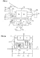
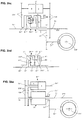
- Figure 1 shows the basic circuit diagram of a stepless, especially hydrostatic Power split transmission with several shift ranges.
- a transmission scheme one such a transmission is shown in Figure 3.
- the transmission adjustment is one of two or more Operating signals, in particular engine speed signal b and accelerator pedal signal or engine control signal a or throttle valve angle DW resulting signal c and / or via a So-called EP adjustment, according to Figure 8, with two input signals C1 and C2 for adjustment of the hydrostatic transmission possible.
- C1 and C2 are electrical quantities based on an electrical one Adjustment with proportional solenoids and in proportion to the adjustment variable of the hydrostatic system.
- the accelerator pedal signal a can be a throttle valve adjustment signal or also as an engine control signal k, which is connected to the engine via the control unit 5, serve, the signal k is identical to the accelerator pedal signal or a modulated variable, depending on certain Operating parameters.
- the accelerator pedal is therefore preferably to be understood as an accelerator pedal.
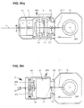
- the invention further relates to a motor vehicle transmission, in particular with Power split, which consists of a stepless converter 4c, according to Figure 2; 3; 3.1; 4; 5, preferably a hydrostatic converter, which consists of a first and a second hydrostatic unit there, both units preferably forming a common structural unit and drive or / and Output of the stepless converter 4c, depending on the embodiment, via direct drive or via intermediate drive wheels.
- the input is divided into two on the input side Power branches, whereby a power branch flows over the stepless converter and before Transmission output again, if necessary, in a summation transmission 5c with the other Power branch is summed up.
- Power split transmissions consist of one or several switching ranges.
- Switching from one area to the other is preferably done at each end adjustment point of the hydrostatic unit, with the Adjustment variable remains unchanged, with the exception of any minor adjustment corrections.
- the Hydrostat four times over the entire transmission range from an adjustment maximum to drive through another adjustment maximum. 3 is in the start-up state at closed clutches K5 and KV and after closing clutch 1 the hydrostatic on its maximum negative adjustment variable set.
- the hydrostat is now used for starting pivoted back to "zero" and beyond to his other understanding, positive Adjustment maximum where at the end of the first and at the beginning of the second switching range Synchronous operation of all clutch elements in the second area by closing clutch K2 and Opening the clutch K1 the second area is switched.
- the summation gear is here as multi-shaft Planetary gear P1 designed, in which the mechanical and hydraulic power adds up becomes.
- the mechanical and hydraulic power flows in the first and in the second switching range via the second planetary gear P2 with clutch KV closed.
- the first and the second shift range is made possible by closing the clutch KR by the direction of rotation in planetary gear P2 is reversed.
- the adjustment maximum of the hydrostatic mentioned in each case defines the point at which the Switching takes place in the next driving range, which is not necessarily the understanding of the Hydrostat must be, but can also be something in front, for example, depending on the load Compensate slip of the hydrostatic transmission.
- the synchronous operation is also too Closing clutch elements not absolute synchronous operation but the synchronous operation range defined, which may include wanted or unwanted synchronism errors caused by the Switching or range clutches can be bridged or still accommodated.
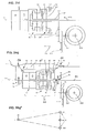
- the transmission versions like. 2a and 3.1 are functionally identical to the described transmission design according to. Fig. 3. They differ essentially in the fact that the respective summation planetary gear in the embodiment of FIGS. 2a and 3.1 is arranged coaxially to the drive shaft 1c, which is why an additional planetary gear set is connected upstream in the summation planetary gear. If you like execution.
- Fig. 2a is also the output shaft 2c coaxial to the drive shaft, while according to execution.
- Fig. 3.1 the output shaft 2c axially offset from the drive shaft 1c by means of a spur gear stage 2d lies. If you like execution. 3.1, an intermediate shaft (73c1, as required in FIG.
- a PTO or PTO shaft connection 2e for example for the tractor, can be realized in an advantageous coaxial position to the drive shaft 1c.
- the third output shaft A3 is not an inner but an outer shaft and is located above the clutches K1 and K2.
- a drive connection is made via the web shaft of P3 with clutch K4 already closed and a spur gear stage 2d to the output shaft 2c.
- Gearboxes of this type are according to DE 40 27 724, DE 41 06 746, EP 0 386 214, US 5,267,911 with part of this invention are described in more detail.
- the invention provides, inter alia, one Improved design of this known transmission and the invention according to DE-A 44 17 335; EP 0599 263. The description of the latter two documents are part of this Patent application and serve to explain details in more detail.
- the invention provides, inter alia, one or several hydrostatic powerless operating points, especially fixed translation points realize.
- the hydrostat at one or more operating points are located in main operating areas, in particular, by appropriately trained facilities switched off or bridged to put it in a de-energized state. This shutdown or
- Bridging device is in the form of a hydrostatic locking device KH or / and an area block circuit and / or a stabilization device KD with or without Direct drive through realized without hydrostatic power.
- the transmission is equipped with a braking device, which in Active connection with the hydrostatic bypass device or translation fixed-point circuit and the stepless converter 4c stands, as partially in DE 44 17 135 A1 described.
- FIG. 4 shows an example of a power split transmission with a hydrostatic one Converter 4c and a summation gear 5c shown.
- the summation gear 5c can also have the function of a branching transmission, which is why the designation below "Summation / branching gear" is used.
- the hydrostatic converter consists of a first hydrostatic unit A adjustable volume and a second hydrostatic unit B preferably constant volume. Both hydrostatic units A and B preferably form one common structural unit, which directly or via drive wheels with the drive shaft 1c and on the opposite side directly via additional drive wheels with a summation gear 5c in Drive connection is established.
- the summation gear is preferably a planetary gear designed, depending on the version, a further gear 5d, with or without switching devices, e.g.
- the Power is divided on the input side into a hydrostatic and one mechanical branch.
- the hydrostatic power share flows through the drive wheels and Intermediate links 227 via the stepless converter 4c and the drive wheels on the Summation gear 5c.
- the mechanical branch is directly or via intermediate links in the Summation gear 5c guided by hydraulic and mechanical power flows be added together and reach the output shaft 2c together.
- the stepless converter or the hydrostatic transmission 4c is in this case with a hydrostatic bypass device Hydrostatic locking device in the form of a brake or clutch KH, which is used to hold the drive shaft 7c of the second hydrostatic unit B or with the housing 19c of the stepless converter or a fixed gear part to couple, so that at Power split transmission known support moments via the clutch or Brake is preferably supported on the gearbox or converter housing in order to Relieve the hydrostatic transmission or keep it torque-free and pressure-free. It is also possible, the hydrostatic shaft 7c of the hydrostatic unit B by another, not shown Separate clutch completely.
- the hydrostatic locking device KH has the task of the stepless converter 4c or the Hydrostatic transmission in the hydraulically inoperative operating states with hydrostatic variable To keep "zero" torque or load-free. This is solved in such a way that the Torque support force from the summing / branching gear 5c with hydrostatic zero position, which is usually in the middle of each switching range, not at the Hydrostat elements but on a corresponding intermediate brake or Coupling element is supported in relation to a fixed housing part or gear part.
- the hydrostatic transmission is inside several times drive through its full setting range, the within each switching range Hydraulically inoperative state with neutral position, that is, with variable "zero" of the Hydrostatic transmission, corresponding to the hydrostatic neutral position. This operating point is mostly in an important operating area of the vehicle, in which a particularly good one Efficiency is required.
- a bypass valve 114c is provided, which is between the two working pressure lines of the two hydrostatic units A and B is switched.
- This bypass valve is automatic or too can be operated manually with the hydrostatic locking device switched, which means both Working pressure lines are depressurized or without differential pressure.
- the hydrostatic locking device or the clutch / brake KH and the bypass valve are usefully over the same Control pressure controlled, but the bypass valve only after the clutch / brake is closed KH is activated such that the pressure feedback after the clutch KH closes the signal or triggers the control pressure to activate the bypass valve.
- the hydrostatic locking device KH can be switched automatically or manually, e.g. B.
- the gearbox in the hydrostatic neutral position or in the vicinity of e.g. maximum 8% of current translation with a pre-programmed time variable for this dwell time, e.g. 2 seconds, triggers the corresponding control signal for the hydrostatic locking device, such that a largely seamless continuous adaptation of the corresponding translation and the Engine speed to the desired speed.
- this operating state and the driver via an optical or acoustic signal Show switching option preferably this operating state and the driver via an optical or acoustic signal Show switching option.
- the hydrostatic lock can also be released in various ways take place, e.g. by a drive or accelerator pedal signal, that is when the Accelerator pedal position or by a load-dependent signal or by various signals through variable operating values can be determined.
- the driving control should be designed so that the transmission efficiency line and the engine’s best fuel consumption line and the Vehicle control depending on the respective operating situation decides whether the nearest gear ratio point with hydrostatic neutral position to be controlled or not.
- a further parameter depending on the load or Noise behavior of the gearbox also saved as a decision factor or be programmed. This can be useful, for example, when used in a car.
- the invention further provides for the hydraulic power branch also to the Switch off translation points of the area switching points. That means that at the end of the old one Switching range and at the beginning of the new switching range, the couplings KB for both areas remain closed and the hydrostat is fixed in this adjustment size and set without load, e.g. B. by simultaneously operating the above-mentioned bypass valve or / and an exact one Alignment or correction of the hydrostatic adjustment such that the two hydrostatic Working pressure lines are depressurized or without differential pressure.
- the performance is in this Switching state is transferred purely mechanically via the clutches or Coupling devices of the two adjacent or adjacent switching areas.
- the Switching signals for this circuit can be given the same signals as for the hydrostatic locking device KH described, can be realized.
- a transmission e.g. B. with four Forward travel ranges, as shown in FIG. 3, are seven fixed translation points in this way switchable with no load hydrostat.
- the invention provides a power split transmission Stabilization device KD or hydrostatic bridging device in front of one or several translation points holds fixed translation settings at which the Hydrostatic power flow can be switched off to further improve efficiency.
- z. B. the output shaft 2c via a gear 10b with Drive shaft 1c via an intermediate shaft 227 by engaging a clutch KD in Drive connection to put the hydrostatic transmission without load after this clutch is closed.
- translation stages provided with a correspondingly assigned clutch will.
- An embodiment according to Figure 3 shows e.g. a stabilization or hydrostat bridging device, in which a direct drive through without a KD clutch Tooth meshing or tooth rolling power, produced between the input shaft 1c and the output shaft 2c and thus the converter 4c and the summation branching gear 5c in the no-load state is set.
- the stabilization device or hydrostatic bridging device KD is also included two or more clutches executable (not shown) to the stepless converter and to decouple the summation branching gear completely.
- the second clutch can be dispensed with.
- the invention provides an improvement in the device according to the German published application DE 41 04 167, claim 17.
- the purpose of preventing switching off in the switching range of two adjacent range switches is Fixed point circuit KB described by closing both area clutches, e.g. K1 and K2, as shown in Figure 7b corresponding to the operating phase Ph 2.
- the Operating variable from a differential value of the hydrostatic adjustment volume ⁇ V or ⁇ nHy or / and a difference value for the load signal ⁇ p or / and a preprogrammed time difference signal or other signals can be.
- the corresponding signal sizes mentioned above can preprogrammed and depending on various operating values, such as operating temperature, Accelerator pedal signal or others can also be influenced.
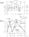
- the functional sequence is such that as shown in Figure 7b, near the translation fixed point KB with the same Driving speed or output speed Nab an automatic increase in Output speed nHy of the second hydrostatic unit B with a corresponding one
- the engine speed nMot is reduced by the difference value delta nMot.
- Figure 7b can e.g. in the first operating phase Ph1 the first range clutch K1 and at Fixed point circuit according to operating phase Ph2, the clutch K1 and K2 must be closed and in In the third operating phase Ph3, the clutch K1 is again closed and the clutch K2 open.
- the difference values delta nHy or delta nMot for the drive motor can be in any size or in any ratio and depending on the vehicle type different sizes e.g. 5% to 10% of the respective reference size.
- the engine speed variable nMot smaller is as the hydrostatic speed variable nHy or in a relation, not shown, the speeds to each other, that in the phase of the fixed point circuit Ph2 the engine speed nMot rotates synchronously with the hydrostatic speed nHy .., as with the concerned Planetary gear members HMot and sHy of the gearbox according to FIG. 3 in the fixed point circuit K1 / K2 would be the case through block rotation of the summation planetary gear P1.
- the clutch for the hydrostatic bridging devices KH; KB; KD is Executable in various ways and can be used, for example, for the hydrostatic locking device KH arbitrarily on one of the intermediate links or drive elements 7c between the second Hydrostatic unit B and the summation gear 5c can be arranged.
- the KH couplings; KB; KD are preferably designed as a positive coupling as in PCT publication DE-A-87/00 324, DE-A-41 26 650 A1 and in European PCT application DE 88/00 563, which Part of this invention are described in more detail.
- the clutch stands out in particular characterized in that they have positively switchable coupling elements with coupling teeth with or without deflection teeth and that by means of a clutch carrier displaceably arranged hydraulically actuated piston the circuit with synchronous operation or in the synchronous operation range is also possible at a certain relative speed. It is also possible, as in described above known publications, additional synchronizers to provide.
- This aforementioned positive coupling has the advantage that it is almost is drag-free since there are no friction elements.
- Clutch as a friction clutch in the form of a cone clutch, such as. B. in DE-A-41 26 650 illustrated to use. This coupling can also be largely free of drag loss as a result of the cone effect the friction surface is relatively small.
- a multi-plate clutch in well-known construction can possibly be designed sensibly.
- Another kind of one positive coupling with mechanical switching elements e.g. B. by means of switching claw, Shift sleeve and / or with servo-reinforced switching elements, depending on the selected Gearbox construction, sensibly applicable.
- the clutch KH is alternatively in a form not shown arranged for the hydrostatic locking device in the summation gear 5c.
- traction booster 77c and clutch KH can a common structural unit can be summarized in terms of space and cost.
- the hydrostat is in all previously described devices for switching off the Hydrostatic operation via the bypass valve 114c described; 216 or / and by a corresponding trained hydrostatic adjustment control to be set without load.
- the hydrostatic transmission is based on the theoretical Adjustment volume size Vth adjusted or adjusted so that no differential oil quantity is exchanged between the working pressure lines 206, 207 when the bypass valve is open or the working pressure lines without the bypass valve 114c, 216 switched or without the bypass valve 206, 207 are almost free of differential pressure.
- the hydrostatic transmission will open in this case differential pressure-free state regulated by various control methods, one method is controlled via the respective differential pressure quantity in such a way that the differential pressure is a Adjustment signal on the hydrostatic transmission triggers, so that a constant adjustment automatically causes at least approximately differential pressure-free state of the hydrostatic transmission.
- the hydrostat adjustment itself continuously a new adjustment variable corresponding to a displacement volume size Vneu adjust depending on the drive torque or according to the respective changing load condition of the engine and transmission varies so that when leaving the Fixed point switching, i.e. at the start of the new circuit or range switch, the right one immediately Adjustment variable or displacement volume variable Vneu is available, the torque-free Condition of the old clutch K1; K2 or clutch KH; KD and the cheapest adjustment size Vnew for the opening signal of the corresponding clutch with almost no torque Condition corresponds.
- the switching sequence for leaving the fixed point circuit and switching in The new stepless shift range is according to the invention in this shift variant accomplished that with automatic torque-dependent constant adjustment of the adjustment on Adjustment variable Vnew takes place in such a way that the bypass valve closes first and then the Opening signal for the old clutch when the relevant torque-free state Coupling member is initiated.
- the bypass valve 114c, 216 is closed, e.g. when shifting from KB to the stepless range, the full torque to the new one Clutch K1 or K2 relocated and the old clutch set torque-free if correct Vneu and open.
- stepless switching range When switching from the fixed point circuit KH or KD to Subsequent stepless switching range is the first by closing the bypass valve relevant clutch KH; KD relieved of the torque and then opened by a corresponding opening signal.
- the bypass valve 114c, 216 is used to optimize the switching quality alternatively designed so that a continuous but nevertheless rapid pressure build-up when Closing process is guaranteed.
- the continuous build-up of pressure can be of various types have a characteristic course and, for example, correspond to a fixed specification by known means such as throttle damping, damping grooves, etc. or depending on one or several operating values, in particular load-dependent values, e.g. through the hydrostatic pressure vary. Electrical-electronic controls can also be useful for a seamless Switching sequence, especially in connection with the described hydrostatic retarder.
- new clutch in the fixed-point circuit KB is the clutch K1 or K2 loaded after leaving the fixed-point circuit and with old clutch understand the clutch K1 or K2 to be relieved of the torque and then opened. Both clutches K1 and K2 are loaded with torque within the fixed point circuit KB.
- the functional sequence of the retarder brake system which is described in more detail in DE 44 17 335 A1, is as follows: As already described, when the brake is applied, the closest or cheapest translation fixed point is achieved by automatically adjusting or increasing the engine speed Simultaneous gear ratio reset adjusted and switched, whereby the hydrostatic transmission is initially in a no-load or depressurized state. For example, when the ratio is fixed via the range block circuit KB, the hydrostatic unit A is generally swung out fully in this state, as a result of which both hydrostatic units keep the corresponding amount of oil in circulation at the same speed without differential pressure within the converter transmission.
- the adjustment unit A Only after the fixed gear ratio has been switched and after the hydrostatic unit A has been adjusted to a smaller volume is the differential oil quantity fed into the brake pressure circuit 206 or 207 and braking power generated when the pressure valve 204 is set or regulated to the appropriate pressure. If the adjustment unit A is adjusted to the adjustment variable "zero", the total amount of oil, which is generated by the second hydrostatic unit B, which is generally designed as a constant unit, is fed into the brake working pressure circuit 206; 207 pumped . If the hydrostatic adjustment is continued by "zero" and beyond, the adjustment unit A also works as a pump, delivering the same pump output and braking power as the constant unit B at the end of its adjustment variable, that is to say with a full adjustment volume.
- both hydrostatic units A and B can also be designed in different sizes and both as adjusting units, the respective braking powers being different according to their size and their associated speed. If the second hydrostatic unit B is also designed as an adjustment unit, further variations are possible, for example in such a way that both units are adjusted simultaneously or first the unit B and then the unit A, depending on the operating situations, can be sensibly regulated in their adjustment variables. In the known transmission designs mentioned at the outset, it makes sense to design the second hydrostatic unit B as a constant unit.
- the service brake is first activated via the automatic brake control or the electronic braking system (EBS), so that a largely no-load is activated when the engine speed is increased at the same time Condition in the hydrostatic transmission with simultaneous automatic adjustment of the hydrostatic unit A is carried out.
- EBS electronic braking system
- the braking effect of the service brake BB increases continuously.
- the hydrostatic transmission is now brought into the corresponding end position or final variable with simultaneous, corresponding engine speed adjustment, after which the service brake immediately after completion of the switching of the above-mentioned translation fixed point while simultaneously taking over the hydrostatic braking power is continuously relieved by adjusting the hydrostatic transmission the service brake.
- This functional sequence can be implemented according to a predetermined program in the EBS by means of appropriate computing processes and processing the signal variables from several operating variables such as brake pressure signal, hydrostatic pressure signal, adjustment signal of the hydrostatic transmission and / or engine speed signal and / or further signals.
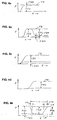
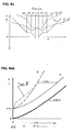
- 2b shows the engine speed behavior in various braking situations, for example for braking operation at 80 km / h.
- the speed point of the motor PB4 is based on an application example for a bus at a speed of approximately 1270 rpm.
- the fixed point switching takes place by engaging the corresponding clutch KH (see Fig.
- the brake control BR or the BRS is preferably programmed here so that this operating point is avoided, so that an automatic speed reduction from 80 to, for example, 68 km / h is effective in order to excessive engine speeds, especially for acoustic reasons and excessive oil temperatures and excessive stress to avoid the components. If the speed is reduced from 80 to 68 km / h, for example, the fixed-point circuit KB can be activated at a maximum speed of 2000 rpm.
- the same functional sequence described above can also take place in the reverse order and mode of operation, as already mentioned above, when transitioning into the flatter roadway level.
- the hydrostatic braking device BH exists in addition to the hydrostatic converter 4c from a first check valve 209, via which the oil flow of the respective High-pressure line 206 or 207 to a switching valve 203 and a downstream pressure control valve 204 is directed.
- the switching valve 203 is an opening signal 214 to release the hydrostatic brake function switched, whereby the flow to the brake pressure control valve 204th is released.
- the pressure control valve 204 is controlled via a variable control signal 215, that depends on the size of the hydrostatic braking force and the hydrostatic pressure certainly.
- the heat exchanger 205 is arranged downstream of the pressure control valve 204, which has a corresponding line 217 receives the heated oil flowing from the pressure control valve and the cooled liquid via a further line 213 and a corresponding check valve 210 reintroduces into the working pressure circuit of the brake system.
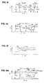
- the brake control RB provides various control strategies that can be installed alternatively or can be pre-selected as required. As shown in FIGS. 4a to 4e and in the functional diagram in FIG. 4f, the hydrostatic brake component FBH can be switched on at will to adjust the Service brake force FBB to reduce as desired.
- Figure 4a shows the braking force curve at a Braking operation in which the hydrostatic brake with the braking force during the braking phase FBH is switched on and the service braking force FBB in accordance with this force is reduced.
- the braking force of the service brake can, depending on the design of the brake control are reduced to zero so that the service brake, in particular for continuous braking operation BB is completely relieved.
- the automatic retarder activation takes place according to the Invention according to a preprogrammed time parameter that a continuous course of allows hydrostatic braking force FBH, the total braking force depending on FB the actuating force remains largely unchanged.
- a Embodiment provides that a corresponding control valve, not shown, or a comparable, not shown electronic, mechanical, hydraulic or other suitable device in which two signal quantities, namely those from the actuating force or from a set value resulting signal size and the hydrostatic brake BH resulting signal size SBH cooperate so that the control signal SBB for Service brake reduced or even to zero according to the hydrostatic signal size SBH is set.
- the hydrostatic retarder BH is controlled via the control signal SHY. At a sudden failure of the connected hydrostatic retarder BH, e.g. due to oil line break i.a.
- the control signal for the hydrostatic retarder preferably results from functions of the service brake or are a follow-up function from the Service brake system, which ensures adequate security according to the requirement of a independent service brake is given.
- the brake signal or feedback signal SBH off the hydrostatic retarder can be selected from the hydrostatic adjustment signals, the hydrostatic adjustment variable, the hydrostatic pressure and / or other sizes result which is a measure of the braking force FBH from the hydrostatic ratarder BH; 4c.
- the brake system can also be used different distribution ratios of the braking forces from the service brake BB or Hydrostatic retarder brake BH can be designed.
- For longer braking processes Depending on the braking time and / or the braking force size, a targeted activation of the Hydrostatic retarder brake with a meaningfully adjusted proportion ratio in various ways executable characteristics are preprogrammed. The most favorable values can can be determined experimentally depending on the vehicle type and other conditions.
- a cruise control device or constant speed control Depending on the road profile can it may be necessary, at the desired constant speed, that different Translation points can be adjusted automatically, especially when each braking force is applied different engine braking force proportion and correspondingly different engine speeds assigned.
- the service brake BB first has the full braking force FBB take over and according to a predetermined variable or constant time parameter or other, the hydrostatic brake or hydrostatic braking force depending on certain operating factors FBH can be added with (or without) simultaneous support from Engine braking effect through appropriate engine braking torque or engine braking force FBM Optimal coordination of the respective braking force components FBH, FBB and FBM can be determined experimentally depending on different operating situations.
- the in Fig. 4a 4b and 4b represent different braking operating situations that arise can be based on the same brake control strategy.
- a manually operated retarder circuit e.g. by an electric brake step switch or continuously variable switch is switchable.
- This device can be used as an additional permanent brake or for a simplified one Equipment in which the hydrostatic retarder serves as a permanent brake can be used sensibly, the respective activation of the continuous brake after a predetermined during the journey Fixed translation and switched fixed point circuit can be switched on manually.
- the in Fig. 4e The illustrated braking force illustration shows the short-term decrease in the hydrostatic braking force FBH , e.g. within a switching phase when changing from one fixed translation point to another. The hydrostatic braking force is reduced within the switching time ts, the Total braking force FBB is maintained through appropriate assistance and activation the service braking force FBB.
- the continuous braking force curve About the switching phase mentioned, as shown in Fig. 4e, according to the invention ensured when using the brake control device described and shown in Fig. 4f.
- the braking force curve within the described Umshaltphase from one to the another fixed gear ratio can also be useful with the help of the FBM engine braking force will be realized.
- the actuating force FF can be within the entire switching phase remain unchanged or can be changed as required, with a corresponding to the change analogous adjustment of the braking force FB takes place as it corresponds to the driver's request.
- the hydrostatic retarder BH In order to ensure the safe functioning of the anti-lock braking system (ABS system), the hydrostatic retarder BH must be switched off as spontaneously as possible during braking, while almost the entire braking force is taken over by the service brake, since the functions of the ABS system are based on service brake equipment. According to the invention, as shown in FIGS. 4i and 4k, the hydrostatic retarder BH is automatically switched off when the ABS system is activated via the electronic brake control RB. A corresponding signal S-ABS from the ABS control R-ABS (see FIG.
- the transition from retarder brake operation to ABS brake operation takes place largely continuously, as shown in FIGS. 4i and 4k.
- the total braking force FB is reduced to FB when the ABS function is activated or FB-ABS lowered according to the different friction coefficients on the braked wheels in question, as is the case with conventional brake systems without retarders.
- the motor brake force FBM with or without a lowering of the engine speed is reduced, which can be preprogrammed accordingly in the brake control and / or transmission control, as shown in FIG. 4k.
- the invention provides that the engine speed is initially maintained after triggering the ABS function in accordance with the previously given engine braking torque in order to maintain a continuous engine speed behavior with frequently changing function changes between ABS and normal braking operation or the aforementioned mixed braking operation or that According to a predefined characteristic, there is a continuous drop in engine speed, which is preferably to be determined experimentally and is to be determined and programmed on the basis of various parameters such as noise behavior, comfort and others.
- the hydrostatic retarder brake function can according to the invention for both Normal braking operation as well as continuous braking operation can be used sensibly.
- Normal braking operation the braking functions described are preferred over a Foot brake pedal triggered depending on the braking force and / or the brake pedal travel.
- the lever position preferably representing a measure of the braking force.
- the service brake BB is activated or the driver forced to set a lower driving speed by braking over the Foot brake or the service brake so that the brake system is prevented from being overloaded.
- the decisive factor for the limitation is primarily the oil temperature or the maximum possible Cooling capacity, e.g. via a temperature signal, which the driver or the brake control the limit of the braking power is signaled and if necessary to reduce the Braking speed forces.
- a corresponding acoustic or optical signal e.g. Flashing light on, prompts the driver to reduce the speed by braking on.
- Automatic speed reduction through automatic use of the Service brake and assistance from the service brake force FBB can be provided by appropriate Control function in the brake and transmission control an adapted driving speed. Cause reduction.
- the speed reduction in the aforementioned case by interim use of the service brake is specified according to the invention such that at service brake is switched off again at the new braking speed
- the Braking speed is reduced so far that the full braking force again over the Retarder brake system and the engine braking effect can be covered.
- the automatic The service brake is used in brake systems with hydraulic and / or pneumatic Energy supply (see Fig. 4g) by a corresponding control signal from the brake control RB realizable.
- the brake actuation can be done in various ways via the master brake cylinder, brake valve, electrical potentiometer, handbrake, retarder selector lever, etc., depending on the vehicle type and the Requirements.
- 4g shows the structure of a brake system e.g. for a Towing vehicle shown.
- the retarder braking system is designed as a hydrostatic retarder ABS suitability (see Fig. 4m and Fig. 4i, 4k, 4l, 4q).
- FBH hydrostatic retarder braking force
- FIG. 4q a signal S-ABS dependent on the ABS control, a corresponding reduction in the hydrostatic pressure caused in the brake circuit 206, 207 of the retarder, in particular by appropriate Influencing the brake pressure valve 204 by the corresponding change in the control signal 215 or / and the hydrostatic adjustment.
- Maintaining the total braking force as unchanged as possible is achieved by lowering the hydrostatic retarder brake pressure in the brake circuit 206, 207 or reduction in the hydrostatic braking force FBH causes a simultaneous, appropriately adapted increase in the service brake force FBB by appropriate control after triggering the control signal SBB Service brake system, as shown in Fig. 4m and 4q.
- electronics automatically compare and adjust the signal sizes SBH and SBB. which results in the total braking signal or the total braking force.
- the brake control system is like this designed that the signal size for the retarder braking force when using the ABS function of the Service brake signal SBB is pushed back by the appropriate amount or that as Subsequent function from the ABS function, the retarder braking force FBH is reduced accordingly, to maintain the independence of the service brake.
- the total braking force remains largely unchanged or, in the worst case, is only lowered as far as it is Allow road conditions optimally.
- the first Hydrostatic brake component FBH almost reduced to zero with a corresponding increase the service braking force FBB, which also includes the ABS function.
- the size of the ABS effect i.e.
- the Brake electronics decide whether and to what extent within the ABS braking phase Hydrostatic retarder brake can be switched on. As shown in Fig. 4q, depending on Given the slip conditions, a more or less large increase in the retarder braking force FBH from the information of the respective slip conditions on the braked Wheels via the relevant control signals for the retarder and service brakes to be triggered. This functional sequence contributes significantly to the service brake share and to reduce brake wear to a minimum.
- the brake system is for safety reasons designed so that if the hydrostatic brake system fails, the service brake immediately previous hydrostatic braking force takes over, with the corresponding service brake signal SBB takes effect on the service brake.
- the means for processing and transferring the mentioned signals can be known electronic, electrical and / or hydraulic-mechanical Facilities and elements.
- the invention provides that depending on the oil temperature and the temperature signal ST a corresponding adjustment of the hydrostatic retarder braking power is adjusted, with the Maintaining the necessary safety according to the permissible oil temperature Reduction of the driving speed by means of a translation reset is preferred automatically takes place and / or a corresponding acoustic or optical signal display to the driver Reduction in driving speed, e.g. by appropriate braking on the Foot brake actuation.
- the temperature signal ST is one of the decisive safety signals here.
- the invention also has a device as Cruise control , which in braking mode when using the hydrostatic retarder as a permanent brake causes the desired speed to be maintained via the actuating device, which can be implemented in various ways, e.g. as a brake switch, brake lever, keyboard or that the desired speed is set via the brake pedal and this brake speed after releasing the brake pedal is automatically held until the driver requests a change in speed by applying the brakes again or pressing the accelerator or accelerator pedal.
- the stored speed is preferably switched off or changed according to a continuous course which, depending on the driver's request and depending on the speed of change of the accelerator pedal, triggers a more or less rapid change in speed according to a predetermined program.
- a temperature signal ST ensures that the retarder braking power is reduced accordingly by automatically lowering the driving speed, e.g. by reducing the gear ratio or / and automatic takeover of part of the braking power by the service brake through a similar functional sequence as described above.
- hydrostatic retarder All of the functions described above for the hydrostatic retarder, also with ABS compatibility, can also be used for gearboxes of various types with assigned hydrostatic retarder known type, e.g. to replace the function of a hydrodynamic secondary retarder.
- This hydrostatic retarder is usually via a spur gear stage with the transmission output shaft connected.
- the hydrostatic circuit is designed so that on the low pressure side Oil inflow and on the high pressure side of the oil outflow and between high and Low pressure side, a preferably controllable pressure valve, which is effective as a brake valve, switched is.
- the hydrostatic unit can be used as an adjustment unit or as a constant unit high circulation oil quantities when the unit is not switched on Retarder function leads to unnecessary performance losses.
- Accelerator pedal or the accelerator pedal position or the cruise control device also the speed determined in braking operation without actuating the brake pedal or other actuation devices.
- the transmission output speed signal d ensures the maintenance of Target speed.
- An engine speed signal b determines the engine braking power.
- the Engine braking power can be dependent or independent of the total braking power that occurs a constant maximum size or a variable size, e.g. in Fig. 4n shown, take. 4n is for a certain operating state when driving varying gradient for a preselected constant speed the total braking force required FB shown.
- the engine speed nMot increased accordingly, which e.g. through the speed signal b to a automatic reduction of the gear ratio 1 / i and simultaneous increase of the FBM engine braking force and simultaneous automatic adjustment of the hydrostatic or Retarder braking force FBH leads. It makes sense, especially for acoustic and acoustic reasons Lifespan of the entire brake system, the engine brake share in a certain customized Pre-program the ratio to the total braking force FB, with a permissible maximum value for the engine braking force FBM and in particular the engine speed nMot is predetermined.
- the invention provides that regardless of the set speed value automatic speed reduction is activated.
- the signals for this can come from a or several operating signals such as temperature signal Sth, hydrostatic pressure signal or / and other signals that affect load or safety are triggered.
- the speed curve described in the retarder braking mode corresponds to the Representations Fig. 41 and 4o of the ideal line, i.e. a line with an infinite number of fixed translation points. Having a limited number of translation benchmarks, however, as already described, exists at the area limits of two adjacent switching areas according to fixed translation point KB, at the point of hydrostatic standstill at fixed point KH and, if applicable, at a further fixed translation point KD, is only a gradual one
- the engine speed can be changed as shown in Fig. 4p. That means one Corresponding gradual change in the gear ratio 1 / i must take place, the above. Ideal line or better preferred line can serve as a given guideline for orientation when switching to the next fixed translation point is to take place.
- Fig. 2b e.g. the maximum possible engine speed points PnMot specified. in the Speed plan Fig.2c is the hydrostatic speed curve nHydrostat, the drive speed nAn and the output speed nAb are shown in relation to constant travel.
- the each Possible fixed translation points KB, KH and KD can be seen in the speed plan.
- FBM engine braking force
- Fig. 4n calculated in the brake control device or in the electronic brake system (EBS) and decided depending on one or more operating parameters or values which one Fixed translation point is most suitable for the current braking condition.
- the brake system can be designed in various ways and can, depending on Vehicle type, e.g. with electro-pneumatic brake control with upstream electronic Control and the like can be executed.
- the control device can also e.g. with a driving dynamics control (FDR) can be combined or expanded.
- FDR driving dynamics control
- the means of realizing the described functional sequences of the individual control and Control devices are known elements or components of electrical, electronic electro-pneumatic, hydraulic or / and mechanical or other type.
- Sensors e.g. as speed sensor, adjustment angle or displacement sensor of the hydrostatic transmission, Pressure sensors, temperature sensor, ABS sensor etc.
- the function of each Signal processing is of a known type and is not or only partially in its details described.
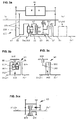
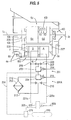
- the invention provides, as in FIG. 4 indicated, the brake valve block 201 'with the hydrostatic transmission or the hydrostatic retarder 4c to connect or block directly, the hydrostatic transmission 4c itself over noise and vibration-reducing elements is mounted relative to the main housing 1.
- the noise isolating Hydrostat storage is particularly in the publications DE 42 35 728 and DE 43 00 456 described in detail.
- Control block which among other things the solenoid valves for clutch control and other details includes, is preferably fixedly connected to the main housing 1, the connecting lines to the hydrostatic transmission 4c and the brake valve block 201 'via known plug connections he follows.
- the oil cooler 205 ' is also connected to the brake valve block 201' via plug connections 202 '. connected.
- the connectors mentioned for the corresponding oil guides have the connection points noise and vibration reducing sealing elements.
- a hydrodynamic converter inform of a secondary retarder or Primary retarders applicable. Both hydrodynamic retarder designs are gem. of the Invention can be activated with the same or similar control elements or control signals.
- a Exemplary embodiment. 2 sees a hydrodynamic retarder 78 at the transmission input as the primary retarder.
- the rotor 81c of this retarder is connected to the drive shaft 1c.
- the stator 79 is fixed to the housing and is preferably accommodated in the gear cover 61c.
- This Retarder acts as a primary retarder, with the braking forces being directly dependent on the gear ratio stand so that even in the lower speed range in contrast to Secondary retarder the full braking effect is available.
- This retarder takes place via pneumatic and / or hydraulic valves, the control signals via the Electronics depending on one or more operating signals and the input values of the Driver are effective.
- This means, known per se, for executing the signals mentioned serve are not shown in the drawings.
- the hydrodynamic retarder (primary retarder 78; secondary retarder 83c) preferably as a continuous braking device and / or as brake support for the customary service braking operations designed, which is among other things the object of the invention.
- This The object is achieved in that the control signals for the control of the hydrodynamic Retarders 78; 83c are dependent on the actuation of the service brake, i.e. that at Pressing the brake pedal a simultaneous or staggered or subsequent, preferred dosed control of the hydrodynamic retarder takes place.
- This retarder control is in addition to the brake pedal signal also influenced by one or more operating parameters. Influencing variables are e.g.
- the invention provides for a minimum reduction in the retarder braking device - hydrostatic retarder or hydrodynamic retarder - to be equipped with a control and regulating device, which contains a predetermined program for the service braking, which provides that a automatic, preferably specifically metered activation of the retarder 78; 83c; 201, as above mentioned, causes.
- the braking program mentioned can be used here, e.g. in Fig.
- the hydrostatic retarder braking force FBH is the same as the hydrodynamic one Retarder braking force, but it must be distinguished that the hydrodynamic retarder at least in some functional processes it reacts more slowly depending on the filling time of the Blading.
- the hydrostatic retarder With the hydrostatic retarder, the activation and brake increase can be done faster take place than with the hydrodynamic retarder, since the braking force can be regulated spontaneously Hydrostatic pressure can be determined and not as with the hydrodynamic retarder Filling speed of the blading of this known brake system is dependent.
- the height Spontaneity and short response times of the hydrostatic retarder are a particular advantage i.a. compared to the hydrodynamic retarder.
- the automatic switch for the respective retarder system can also due to their characteristic differences can be programmed accordingly differently, the hydrostatic retarder also as pure service brake can act, especially when braking on one Fixed translation point or near a fixed translation point.
- the Brake pedal on the hydrostatic retarder causes a very fast hydrostatic adjustment or / and a corresponding hydrostatic pressure change via the relevant pressure control valve 114c; 204 (Fig. 2 or Fig. 4).
- the object of the invention is, inter alia, a switching device, preferably for automatic switchable gears, in particular for continuously variable branching gears of the type mentioned above positive clutches with or without deflection teeth or friction clutches with conical friction surfaces, as known from DE 41 62 650, or also with known multi-plate clutches create the high switching quality without interrupting the load.
- the leakage oil losses of the hydrostatic transmission cause, as mentioned at the beginning, an inevitable speed slip of a hydrostatic shaft 7c.
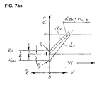
- This speed slip in conjunction with a continuously variable power split transmission with several driving ranges within the range shift, as shown in FIG. 7, has the effect that, for example, in train operation to achieve the synchronous state of the clutch members to be shifted, the variable V alt by the dimension X am Switching point must be greater than the theoretical value in order to reach the synchronizing point of the clutch elements to be switched at switching point S.
- the adjustment variable or the maximum adjustment volume is to be dimensioned correspondingly large when designing the gear unit.
- the speed slip Due to the mentioned function reversal from pump to motor and vice versa after switching to the next switching range, the speed slip also has the opposite effect, which corresponds to an adjustment correction quantity by the dimension Z and thus the adjustment variable V new, after which the torque changes from the old to the new Coupling has taken place and the opening signal for the old clutch is triggered.
- the correction variables X and Y have different variables, due to the respective transmission design and range variables corresponding to the different variables of the hydrostatic pressures ⁇ p1 and ⁇ p2 or ⁇ p old and ⁇ p new at the end of the old and the beginning of the new shift range.
- B1 means 1
- B2 means 2
- the functional sequence is described in more detail in the publications mentioned at the beginning.
- the adjustment correction is used to optimize switching Operating values of the drive motor M controlled / regulated. Determining the size of the Adjustment correction X; Y; Z is the respective or current drive torque Tan des Transmission or the engine torque Tmot.
- the closing process of the new clutch after the end of the old switching range takes place in the synchronous state as with all of the aforementioned solutions Coupling members of the new clutch, preferably two or more speed sensors by comparing the speeds of at least two transmission elements the synchronous state determine and trigger the switching pulse for the new clutch.
- the current drive torque of the gearbox or engine torque Tan determines the load size of the Hydrostatic transmission and the corresponding speed slip of the hydraulic motor / pump and thus also the size of the required adjustment correction within both closed Couplings.
- Each drive torque is therefore also a specific adjustment variable or Displacement Vneu assigned to the torque-free state of the old Coupling corresponds, after which the opening signal for this clutch is triggered.
- Torque changes within the shift phase, with both clutches closed are automatically taken into account in this correction device, since the current one is always Drive torque Tan or motor torque Tmot the opening signal of the old one Coupling determines or via corresponding, resulting signals to open the old one Clutch triggers. Regardless of whether it is a train upshift, train downshift, The system recognizes the overrun or overrun downshift cheapest opening point or the new adjustment volume Vneu to trigger the Opening signal of the old clutch.
- the system also recognizes the respective operating status by that the engine is toured accordingly at thrust torque and depending on the speed corresponding to signal b, a corresponding braking torque or negative engine torque or Thrust torque size is recognized and from the corresponding signal sizes b, a or Brake signal f torque magnitude Tmot; Tan and torque direction determined and from it the shift correction quantity and direction and Vneu to open the old clutch defines and signals.
- the correction values and are reversed Correction directions take place, the displacement or the manipulated variable when shifting up Valt is less than Vneu and when switching back, Valt is greater than Vneu. This corresponds to that general characteristic shift correction behavior in such hydrostatic-mechanical, but also purely mechanical power split transmissions.
- the speed slip variables of the Hydrostatic transmission before and after the range shift with the same input and output torque at each range switching point each be very different according to gearbox design and division of areas.
- the correction variable ratios X to Y are different. Accordingly, in tax and Control system the correction quantities or correction quantity ratios X to Y programmed, i.e. it is basically every drive torque for every range switching point a separate manipulated variable or displacement volume variable Vneu is assigned and preprogrammed, the load conditions and others that change depending on the switching phase Factors can be corrected so that there is no switching shock in all operating states Range switching is guaranteed.
- each for the determination of the engine torque suitable signal quantities in the cruise control or control and Control device programmed.
- RQ control of each throttle or Accelerator pedal position and given engine speed a certain engine torque assigned so that throttle or accelerator position signal and engine speed signal a Give information about the respective engine torque, according to which the new displacement or the variable Vneu is determined and the opening signal for the old clutch is initiated can be.
- RQV control each accelerator or accelerator pedal position corresponds to one specified engine speed size regardless of the engine torque. This type of regulation is it is therefore necessary to determine the engine torque, a corresponding signal that the Filling level of fuel injection or a similar signal size for the Torque determination is suitable to use.
- This correction variant is in contrast to the one described earlier Variant not required, the adjustment correction variable Z from a hydrostatic pressure signal or to determine or calculate a correction variable X or Valt given before the start of switching, but the opening signal can always from the currently effective drive torque Tmot or Tan can be determined.
- the correcting variable or Vneu is usually provided by an appropriate displacement sensor or sensor that detects the Adjustment angle or adjustment path of the hydrostatic transmission signals.
- Known Verstelltik- or electrical adjusting current size are used, provided that this for the Determination of the correct opening signal are suitable for the old coupling ..
- a pressure sensor for recording the respective hydrostatic pressure is in this correction variant not mandatory.
- Vneu can be the difference between Vtheoretical and Valt or one Program should be provided, which does not require the help of Vtheoretical by primarily from experimental determination, the corresponding Vneu is assigned to each Valt.
- the adjustment values of the hydrostatic transmission can be recorded via a potentiometer which is known per se and which defines the adjustment angle or the adjustment path, a proportional current determining the adjustment angle or the adjustment volume of the hydrostatic transmission or via a current quantity, which is also a measure of the Indicates the adjustment angle or the adjustment path of the hydrostatic transmission.
- the individual range clutches or clutches for the fixed-point circuit are expediently via known electromagnetic valves 61; 62; 63; 64 or via solenoid valves 64 designed with a non-return function controlled.
- a proportional valve 3 which can be implemented in various ways in a known manner, is primarily used for the hydrostatic control.
- a control sensor or displacement sensor with feedback in a known manner.
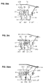
- at least two speed sensors Sa; Sb; Sc; SD; Se; Sf (see Fig. 8) is used.
- the speed sensors can be connected directly or indirectly, for example through interposed spur gear stages, or in active connection with the two hydrostatic units A and B.
- the transmission has several sensors as shown in Fig. 8. The transmission input speed is measured via the speed sensor Sc and the output speed via the sensor Sd, which are also used to determine the gear ratio given in all operating points.
- the sensors Sa and Sb or Sa and Sc are preferably suitable for determining the synchronous state or range of the range clutches to be switched.
- the other sensors Sf and Se show the respective speed of various transmission elements.
- the speed signals b for the input speed from the sensor Sc and the output speed signal d from the sensor Sd and the sensors for the transmission elements Sf and Se can be used.
- one or more of the replacement sensors mentioned automatically take effect to determine the respective synchronous state.
- the failure of a sensor is indicated to the driver optically and / or acoustically by a corresponding signal for immediate damage repair. Basically, only two sensors would be sufficient to fulfill the basic functions, the information, which area and the adjustment signal is required for determining the translation.
- the adjustment change mentioned can be a one-off or repeated upward and / or downward adjustment of the adjustment member within the synchronous range, which causes a corresponding change in the adjustment current or the adjustment signal of the hydrostatic transmission.
- a direct countermeasure in one and possibly subsequently in the other adjustment direction is generated by preferably impulsive adjustment impulses, whereby, depending on the type of execution and requirement, a Shaking effect can arise.
- a targeted functional sequence provides that this switching effect or this switching aid device is only activated after a pressure feedback of the pressure piston via a corresponding feedback line 57; 58; 59 has taken place in the control and regulating device 5.
- a further variant provides that the switching effect mentioned is triggered after a defined period of time, for example twenty milliseconds, after triggering the switch-on pulse for the new clutch and lasts for a fixed, in particular experimentally determined period of time.
- the specified time period can be a constant value or a value dependent on one or more operating values, for example the oil temperature.
- a single adjustment pulse in one adjustment direction which acts as an interference pulse in relation to the synchronous state, is sufficient.
- the optimal effectiveness of this switching function can be determined experimentally. After the functional sequence of this shifting aid expires when the clutch to be shifted is largely torque-free, there is no negative influence on the shifting quality.
- This shifting aid described above is particularly suitable for positive-locking clutches with or without deflection teeth as already described at the beginning and described in more detail in the documents DE-A-41 26 650 A1 and the PCT application DE 88/00 563.
- the brake signal f that is effective for the gear ratio feedback control can be dependent to the brake actuation force and / or to a greater or lesser extent depending on the engine speed stand, preferably in the lower speed range and starting range, e.g. at the When the brake is released, the amount of braking via the service brake can be very low or almost zero can.
- the brake signal f can therefore, depending on the type of vehicle, according to a specific one Brake characteristic a fixed or changeable to different operating parameters Represent characteristic curve.
- the brake signals 113; 217; 215 of the braking, control and regulating device for the Retarder brake system can advantageously indirectly or directly with the brake signal f in Be brought into operative connection or be effective as a brake signal f.
- An improvement of the range switching within the braking and / or overrun mode is achieved by the combination of the transmission-side braking via the influence of the Brake signal on the gear ratio and the interaction with the described Bypass valve.
- the engine speed is increased due to the influence of the brake signal the corresponding change in ratio of the transmission, which at the same time the spontaneity of the Switching sequences and the adjustment speeds is positively influenced because of higher speed Control pressures and control oil quantity, both for the hydrostatic adjustment and for the clutch switching elements is improved.
- an automatic filling or Throttle valve position signal and possibly other operating signals becomes one Harmonious, comfortable range switching, even in extreme braking and pushing situations achieved.
- the braking components are automatically via the normal service brake system and the transmission brake is metered in such a way that the transmission and service brakes interact is prevented by a correspondingly adjusted dosage of service brake and Transmission or retarder brake system is achieved through active connections of the aforementioned signals.
- the amount of engine braking is dosed so that the engine noise is acceptable remains held.
- the Engine braking power should be very low despite a relatively high braking force, meaningfully one appropriate engine speed control depending on the driving speed and / or the gear ratio and / or the brake size can be preprogrammed. It is therefore advantageous because at low speeds the amount of transmission braking to be supported by the engine is relatively large even at low engine speed due to the correspondingly large Gear ratio.
- the invention provides for an engine speed reduction with preferably continuous course with the vehicle deceleration or with falling Pre-program the travel speed within the braking mode.
- the invention further provides an improvement of the turning or shuttle operating device with an IFA pedal, as is known from the publications WO 96/02400, DE 195 42 993, DE 196 41 723 and others, which are part of this invention.
- the function of the IFA pedal can proceed in this improved or further alternative as follows: After releasing the IFA pedal, an engine control signal is automatically triggered to increase the engine speed, e.g. as in the speed line nMotIII acc. 8ab and 8ac. At the same time, a translation change is made to set the vehicle in motion.
- a predetermined driving speed v arises; or output speed nAb on.
- the engine speed nMot can be different in relation to the driving speed, as shown in FIG. 8ab.
- a constant engine speed can also be specified, whereby a differently sized engine charge is triggered according to the resistance.
- the engine speed is of different sizes, for example between two predetermined engine speed lines I and II.
- the driving power required at the respective driving speed which can vary in size depending on the operating conditions, is decisive for the respective engine speed.
- the IFA pedal is similar to an inverted accelerator pedal, with the pedal release travel s or / and the inverted pedal force F-IFA determining the size of the motor control signal.
- An additional influence of the motor control signal is the given driving resistance, which has an effect on an engine pressure and thus contributes to a further increase in the engine speed according to its size.
- a setpoint / actual value comparison of the output speed nAb is preferably used as the control function, from which the signal for raising or adapting the motor control signal is formed.
- the control device is programmed so that if the output speed nAb deviates from, for example, 5%, an adaptation of the motor control signal is triggered automatically to adapt the motor output accordingly.
- an adaptation of the motor control signal is triggered automatically to adapt the motor output accordingly.
- a more or less large deviation of the actual value line from the setpoint line of the output speed nAb or v can be specified for the adjustment control .
- the controlled variables NEEDED, NEEDED should preferably be determined experimentally, whereby a different relationship can be achieved via the IFA pedal travel s-IFA or the pedal force F-IFA.
- the braking device described above via the hydrostatic braking system can be advantageously controlled via the signals of the ABS system.
- An emerging slip signal or ABS signal can activate the bypass valve automatically during braking 114c; 216; or / and cause a reset of the hydrostatic adjustment, whereby automatically by the influence of this or these signals a no-load state or torque-free or a corresponding torque-reduced state is produced.
- the bypass valve 216 is adjusted to a correspondingly changed or reduced hydrostatic pressure.
- the braking force via the gearbox or the brake retarder or hydrostatic retarder can be used here correspond to the size of the ABS signal.
- the invention further provides for range switching for both up and down Downshift, pull or push shift in combination of the ones already described Shift correction or / and as an alternative to a shift correction device before, according to how in Fig. 7c, the switching correction quantity Z over an adjustment correction time tk is determined.
- the adjustment correction time tk determines at the time of switching or in the switching phase depending on the adjustment speed, the size of the correction value or path Z.
- the decisive factor here is the control flow or the delivery volume Qk.
- the effective one Control current Qk is determined by various variables such as Feed pump delivery volume, speed, control pressure (constant or variable), internal Throttling effects, oil temperature etc. determined or influenced.
- the size of the The adjustment speed or the adjustment current Qk can be determined experimentally in further dependency on the different operating states, - engine speed, engine control signals such as throttle valve position, accelerator pedal position, oil temperature etc. - from these
- the aforementioned values are recognized by the control device or the electronics as to which adjustment correction time in which operating state for determining the respective correction variable or the new one Displacement Vneu is required.
- the temperature in particular the oil temperature, oil viscosity and, if appropriate, others the volume flow of the adjustment devices, leakage oil changes and the switching time influencing factors are taken into account by appropriate signal processing in the Control device.
- the type and size of the load can be specified in the program, which means a corresponding adapted enlargement or change of the correction (Z; tk) is realized.
- control and regulating device or electronics furthermore an automatic change and adjustment of predetermined values, in particular depend on the operating time and / or type of application.
- the adjustment mentioned can be based on can be realized in various ways, e.g. such that malfunctions or malfunctions in the control device or electronics are recognized, from which e.g. one out of a bump resulting signal or interference signal causes a change in one or more predetermined sizes or fixed values takes place, so that despite changing operating values, e.g. the leakage oil quantity, the correction quantities tk; Z can be adjusted so that good switching quality is preserved or improved.
- Triggering signal for this correction or internal Correction of preferably predetermined or prevailing variables can be one, in particular Torque change occurring during the switching phase of an engine or Transmission link or a torque or speed changing signal or / and Rate of change and / or change in a mass force or generally a shock or jerk-indicating signal.
- a suitable signal variable for changing internal specifications or The engine speed signal in particular in the constant driving range, can be fixed values, whereby at a deceleration shock triggers an engine speed increase, which automatically causes a appropriately adjusted change of one or more of the internal default values or Fixed values and / or signal size is effected, so that in this case e.g. a corresponding Increasing the adjustment correction value tk or Z is achieved.
- signals can also be a signal that results from the Change in a mass force mentioned above results, for example, by the Mass change within the switching sequence a decision to shorten or Extension of the switching correction time tk or the adjustment correction variable Z is realized.
- the change in the internal fixed values essentially depends on the course of the operating time changing values, e.g. depending on the wear of individual elements or / and as a function of a strongly changing operating characteristic of a vehicle can stand. This means that to optimize or maintain good shift quality Electronics or control device the decision for a change of one or more internal fixed values preferably from the information of several switching processes to get the determine the most suitable change value.
- the invention further provides that with regard to the reduction in switching time Synchronous speed range, which includes the amount of inaccuracy, depending on one or more operating parameters can be of different sizes.
- the electronics take into account, for. B. in a very rapid change in translation the required closing time from the time the signal is triggered until the start of the active closing process. Accordingly, the clutch lock signal accordingly early before reaching the synchronous state or before reaching the permissible Synchronous range initiated.
- the aforementioned synchronous range can depend on the type of clutch - friction clutch, e.g. inform of a multi-plate or cone coupling or positive coupling with or without deflection teeth - be of different sizes. The exact values are preferred to determine experimentally.
- the information for the most suitable switching time is taken from the Electronics e.g. from the speed / force of change of the translation or / and / or Actuation force / speed of accelerator pedal and / or brake pedal or others, therefor suitable operating parameters or influencing factors resulting from the experimental determination and provide insights.
- the feedback signal to indicate the closed new clutch gives the impulse for the initiation of the correction adjustment Z or tk.
- the opening time for the old clutch can also be varied differently or be preferred by a corresponding amount tkv. ..
- the switching correction device with time-dependent switching correction has the advantage that an expensive hydrostatic pressure sensor and in some cases also one Hydrostat adjustment path sensor (potentiometer; displacement sensor) can be dispensed with.
- This The method is suitable for both the area switches and the fixed point circuits KB; KH; KD and also for reversing circuits, e.g. for reversing operation one Working machine - wheel loader, tractor front loader etc. -.
- Positive couplings with deflection teeth or friction clutches can do a lot the opening signal reduces the switching time even before the torque is completely transferred from the old to the new coupling, i.e.
- the opening signal is thus around the time tkv preferred, where tkv can be influenced by one or more of the above-mentioned operating signals or / and change signals.
- the adjustment process of the hydrostatic transmission can thus largely continued continuously even during the opening process of the aforementioned clutch are thus a function overlap of the opening signal or the opening process of said clutch and the hydrostatic adjustment is effective, thereby reducing the switching time and high switching quality is achieved.
- the system especially for the shift correction and / or other functions, recognizes Thrust, pull or upshift in a simple manner from the respective engine speed and Throttle valve position or the size of the motor control, from which the correction direction of the Hydrostat adjustment device is determined (see Fig. 7 and 7ab).
- the hydrostatic-mechanical power split transmission G shown in FIG. 3a II has four hydrostatic-mechanical forward driving ranges, which have the same function as the Gearbox version G I, gladly. Fig. 3 and is described in more detail earlier.
- the Gearbox G II has no reverse range. It can be combined with a subordinate one Reversing gear W1 or W2 or W3 as in Fig. 3b; 3c and 3ca shown.
- the Reverse gear W1, W2; W3 enables the same number for reverse operation Switching ranges as for forward operation.
- When using the planetary reversing gear W1 3b are approximately equal forward and reverse speed ratios realizable.
- the planetary reversing gear W2 according to FIG.
- Gearbox versions G I and G II can be of the same Basic components - hydrostatic transmission 4c, summation planetary gear 5e; P1, clutch pack K1 / K2 - be trained so that a meaningful gear family for a wide range of applications can be realized with largely the same construction elements or construction groups.
- the Reverse gear W1 like. Fig. 3b consists of an input-side ring gear HE, a output side ring gear HA and a clutch or brake KRW for the reverse range and a clutch or brake KVW for switching the forward driving range.
- a planet carrier PT1 intermeshing planet gears PL1 and PL2 are mounted, wherein the planet gear PL1 in the first ring gear HE and the second planet gears PL2 in that engage the output side ring gear HA.
- the planet carrier PT1 is with the housing over the Coupling or brake KRW connectable.
- the KVW coupling provides a direct connection between the Output shaft 2c of the transmission G II with the output shaft 2c 'of the transmission for the forward driving range
- the reversing gear version W2 acc. 3c has a planetary gear PW2 with a sun gear S ', a planet gear P' and a ring gear H 'and one Clutch or brake KVW and another clutch or brake KRW for the reverse driving range.
- the sun gear S ' is in drive connection with the output shaft 2c of the transmission G II, the planet carrier PT2 is connected to the housing via a clutch or brake KRW can be connected and via the clutch or brake KVW, the transmission output shaft 2c with the Output shaft 2c 'of the transmission can be coupled for the forward driving range.
- the Gearbox output shaft 2c directly connected to gearbox output shaft 2c '.
- switching the reverse driving range via the clutch or brake KRW is carried out by the planetary reversing gear PW I or PW II a reversal of the direction of rotation.
- the planetary reversing gear W2 can also be designed in a form not shown so that the sun gear S ' abortive member and the ring gear H 'represents the driving member. At this Embodiment may reverse speed versus forward speed according to the number of teeth ratio of sun gear S 'and Ring gear H 'can be enlarged. Depending on the vehicle requirements, this solution can also make sense will be realized.
- the planetary reversing gear W1 and W2 can be compared to conventional spur gear reversing gear small and inexpensive as separate units for the application too other transmissions can be realized.
- the reversing gear can alternatively also as a helical reversing gear W3, as shown in Fig. 3ca.
- the brake control device sees different functional alternatives for the Translation characteristics after releasing the brake pedal before.
- Known institutions After the brake is released, the transmission is held in place. However, this leads to Dependency on certain operating conditions to sometimes uncomfortable operating behavior.
- the Invention provides a brake control device that does not hold the translation but one adapted to the different operating states or operating parameters Gear ratio change after releasing the brake.
- Gear ratio change after releasing the brake To release the brake when Maintain driving speed and / or the engine braking ability can be used advantageously make, as it usually corresponds to the driver's request, the invention provides that after brake released a transmission reset (corresponds to increasing translation) he follows. The engine speed is at the same time through the gear ratio reset raised while increasing the engine braking torque.
- Adjustment characteristics of the translation change can be specified.
- the adjustment characteristic mentioned may have a function controlled by the engine speed signal, the Adjustment speed can be made dependent on various operating parameters. E.g. it makes sense to increase the reset speed when braking on a slope program that the driving speed is maintained as far as possible or at least for the Driver a smooth and pleasant transition to the operating state when released Brake enables.
- the output speed signal of the transmission can be used as a control signal serve for the translation change and change speed, being by a Actual / setpoint comparison the corresponding signal on the gearbox adjustment is triggered.
- the for the engine speed determining engine braking torque can be as a constant variable or as a variable depending on various operating factors is preferably determined experimentally and depending on the type of vehicle can be different.
- an automatic translation is set, which is dependent on the Engine speed is programmed, a predetermined fixed or preselected by the driver or adjusted engine speed within the overrun determined.
- a combination of the engine braking torque and Combine hydrostatic retarder at the same time in the function preferably a relative low and acoustically pleasant engine speed that a certain engine torque is preprogrammed.
- the braking component of the retarder is based on the Engine speed or the engine speed signal, the hydrostatic adjustment being an adjustment variable takes, which corresponds to the remaining braking torque or the remaining braking power.
- the aforementioned braking functions can be applied with permanent brake application or with keep the brake released for a certain continuous operation or within certain limits stay.
- the driver's request and / or certain operating signals are decisive here such as. Oil temperature that only allows a certain limit. Suitable means are: described hydrostatic brake system and the brake control, the main control signals the Engine speed, oil temperature and the brake signals entered by the driver are.
- the invention provides, in addition to the devices with IFA pedal known from the documents DE 196 41 723, DE 196 01 001, DE 195 42 993 and others, a further type of driving control, according to which the IFA pedal and the accelerator or accelerator pedal F a very user-friendly and efficient turning operation is possible.
- the starting or first speed range is initiated via the IFA pedal in a first speed phase Pha.
- a certain speed point Pa3 or certain output speed is reached until the IFA pedal is released completely in accordance with the IFA pedal travel s-IFA or the pedal force release F-IFA.
- the functional sequence up to this speed point Pa3 is identical to the previously described functional sequence according to the diagram in FIG.
- a defined speed Pa3 or an unillustrated power point is reached that has a constant predetermined value or can have a pre-programmed size or a variable size that can have different size ratios depending on one or more operating sizes.
- a fixed speed variable can be set, or with this IFA pedal position Pa4
- a driving speed is automatically set that corresponds to this power.
- the speed Pa3 in the latter variant can have very different sizes depending on the type of application and the preselected value.
- the further speed phase PhB is brought about by actuating the accelerator or accelerator pedal F by initiating an additional increase in the engine speed or engine power in order to increase the output speed Nab in accordance with the driver's wish.
- the control provides, depending on the vehicle type and other different control strategies, that each accelerator or accelerator pedal position is based on a predetermined fixed driving speed or a certain driving performance which corresponds to a driving speed corresponding to the respective engine power via the stepless control device.
- very different driving strategies can be implemented, which are subject to different characteristics depending on the type of vehicle and type of application.
- the rule characteristic mentioned can correspond to a fixed specification or contain different variations to be made by preselection.
- a selection device to pre-program different engine speed profiles, such as shown in the engine speed lines nmotI and nmotII, which can be selected step-by-step or continuously, for example, when using RQV-like engine control. It is also possible, for example via a Hand throttle increase or pre-select the engine idling speed. It makes more sense to make a variable engine speed characteristic infinitely variable or preselectable over several individual stages, the driver being able to make an individual selection, for example depending on the type of application and / or the type of vehicle or / and various other conditions and requirements. The latter embodiment has the advantage of high spontaneity despite the relatively low overall engine speed level. A reasonable coordination of the various parameters mentioned can be determined experimentally.
- a mixed control for example with electronic motor control
- IFA control reverse gear control
- the above-described driving control for turning operation via the IFA pedal is preferably implemented by a separate control program which is activated by a separate preselection, for example by a corresponding push button or by automatic preselection in conjunction with one of the preselection or actuation devices, for example for the front loader Operation or a work operation intended for shuttle operation.
- the IFA regulation can be a fixed regulation program or a regulation program that can be changed manually contain.
- the variable program which can be adjusted continuously or in stages provides that e.g. for shuttle operation for fine work on a work machine on one low engine speed level, especially in the starting area, is designed to e.g. Work to be able to perform precisely and precisely at the lowest speeds.
- the engine speed level may be higher i.e. that the idle speed has been raised to a correspondingly higher level from the outset high performance and adjustment speed as well as higher driving speeds enable, e.g. is required for work machines such as wheel loaders or forklifts.
- the Overall characteristics can be changed depending on the type of vehicle and / or type of application be, e.g. the speed point Pa3 (see FIG. 8ac) when the IFA pedal is released corresponds to different speed point, e.g. can be between 3 and 10 km / h.
- the idle speed nleer does not correspond to the usual engine idle speed, but a new fixed or arbitrarily selectable starting speed or an engine speed that increases immediately when you release the IFA pedal, e.g. like in speed curve nMot III (see Fig. 8ab and 8ac) shown.
- the invention further provides a transmission family for a wide range Range of applications or / and for a wide performance range or / and for adaptation different conversion areas or gear spread by different To create a combination of the largely designed as standard units.
- the Adaptation to different output sizes or the desired gear spread is done by Corresponding number of switching ranges varies with the same size of the Hydrostat package 4c and preferably constant mechanical assemblies or Components. This means, for example, that for vehicles of different types and / or different Performance classes or for a wide performance range the same hydrostatic module 4c can be used, however, different mechanical assemblies to one another certain gearbox design Af1; Af2; Af3; Af4; Af5 can be combined.
- the size of the vehicle-specific conditions is a different number of forward and Backward areas and also area sizes possible by appropriate type of combination. Furthermore, according to the invention, it is possible to add to the range of applications expand, in that two or more sizes of the hydrostatic transmission 4c to choose from To be available. This allows extensive adaptation to vehicle-specific conditions given. For use in a construction machine, e.g. Wheel loader at the high When maneuverability is required, it makes sense to combine a gearbox with little Realize switching ranges. Here, the necessary conversion range or the gear spread adapted by appropriate selection of the hydrostat size.
- the two forward and two backward areas consists of a four-wave Summation planetary gear PS1 with two input shafts E1 and E2 and two Output shafts A1 'and A2', to which a planetary gear W2 or W1 is assigned.
- the two output shafts of the summation planetary gear PS1 are alternately over Clutches K1 and K2 with the downstream planetary gear W2 and W1 connectable.
- the summation planetary gear PS1 has four shafts and is happy to match the design. Fig. 3d and has two input and two output waves.
- On a planet carrier A1 are interlocking planet gears Pl1 and Pl2 arranged, being in first planet gears Pl1 a ring gear HE2 in drive connection with the second hydrostatic unit B and in second planet gears Pl2 the ring gear HE1 which is in drive connection with the drive shaft 1c engages and the web shaft A1 as the first output shaft A1 with a first clutch K1 and the second output shaft A2 forms a sun gear SA, which in first planetary gears Pl1 engages and can be connected to a second clutch K2.
- the two output shafts, web A1 and sun gear SA can be connected to the output shaft 2c via the two clutches K1 and K2.
- a second, preferably three-shaft, planetary gear unit PR1 serves for the reverse area, the ring gear H3 with the bridge A1 , whose sun gear SR with the output shaft 2c and its bridge shaft PT2 can be connected to the housing of the transmission via a clutch or brake KR.
- This transmission version has two hydrostatic-mechanical forward and one hydrostatic-mechanical reverse range.
- the first output shaft is web A1 - with the SR sun gear and the sun gear SA with the ring gear H3 connected. This version is advantageous for vehicles with a lower reversing speed.
- Fig. 3da is the gearbox execution acc. Fig. 3ha with the essential difference that the hydrostatic transmission 4c with the units A and B coaxial to the summation planetary gear PS1 , the clutches K1 and K2 and the planetary gear SR is arranged.
- This has the advantage that the spur gear stages connecting the hydrostatic transmission can be omitted.
- the transmission is driven via a spur gear stage 2d on the output side, which connects the drive between an axle differential DIF and the output shaft 2c manufactures.
- the axle differential DIF is offset coaxially to the drive shaft 1c arranged.
- This gearbox is particularly suitable for machines such as tractors.
- the spur gear stage 2d can be saved as in FIG. 3hb shown, the output shaft 2c represents the bevel pinion shaft for the bevel gear of the differential gear DIF.
- the bevel gear drive KE is designed, for example, as a hyboid drive with an axial offset AX, so that the PTO shaft or power take-off shaft can be arranged on one of the two drive shafts TW at a sufficient distance.
- the summation planetary gear PS1 like Fig. 3d and 3da and PS1 gladly. 3ha and 3hb are functionally the same and differ only in that, depending on the arrangement of the hydrostatic transmission 4c and 4c the position of the two ring gears HE1 and HE2 are interchanged in the axial direction.
- gearbox design gladly. 3d and 3da is the summation planetary gear PS1 usable, the spur gear stages 26c and 228 also being swapped in the axial direction in a manner not shown.
- the summation planetary gear PS2 is another Subordinate planetary gear combination PN1, which preferably consists of two planetary gear stages PR1 and PV exist.
- the three output shafts A1, A2 and A3 are alternately over the clutch K1, K2, K3 can be connected to the secondary transmission PN1.
- the summation planetary gear PS2 is five shafts and identical to the Af2 version.
- This summation planetary gear is a planetary transmission PN2 in this embodiment assigned, which consists of a planetary gear stage PV1.
- the three output shafts A1, A2 and A3 of this summation planetary gear PS2; PS3 are also over three clutches K1, K2 and K3 can be connected to the PN2 secondary transmission mentioned alternately.
- a further gear in particular as a planetary reversing gear W2 subordinate, which consists of a planetary gear set PR2 and a clutch KVW and further clutch KRW exists.
- the planetary gearbox W2 described above is or W3 downstream, which enables the same number of forward and reverse areas.
- a hydrostatic-mechanical power split transmission which has two forward and two reverse ranges, the first forward driving range and the reverse range operating purely hydrostatic and the second forward and second reverse range with power split.
- the transmission consists of a hydrostatic transmission 4c with a first hydrostatic unit A of adjustable volume and a second hydrostatic unit B, preferably of constant volume, and a summation planetary transmission SP4; SP5; SP6 and a first clutch K, which is closed in the first forward and reverse range, and a clutch KV for the second forward range and a further clutch KR for the second reverse range.
- One link of the clutch KV and one link of the clutch KR are in constant drive connection with the drive shaft 1c '.
- the coupling members or coupling halves with their shafts EV and ER have opposite directions of rotation.
- the associated spur gear stages 26 '; 27 '; 28 'or 29' and 30 ' are designed accordingly, the drive wheel 27' serving as an intermediate gear in the first spur gear stage.
- the first hydrostatic unit A is driven via gearwheel 28' and the input shaft EV via gearwheel 26 'which, when the clutch KV is closed, in the second forward driving range the mechanical power share on the summation planetary gear SP4; SP5; SP6 transmits.
- the mechanical power part is transferred via the further gearwheel 30' to the counter-rotating input shaft ER with the clutch KR closed, within the second reverse driving range, to the summation planetary gear SP4; SP5; Transfer SP6.
- the second hydrostatic unit B is in drive connection with the second shaft H4; H5; H6 of the summation planetary gear SP4; SP5; SP6, via which the hydraulic power component is guided within the second forward or second reverse range to the summation planetary gear.
- the power added up in the summation planetary gear becomes output shaft 2c transfer.
- the power when the clutch K is closed becomes purely hydrostatic via a drive train 31 ', 32' connected to the second hydrostatic unit B to the output shaft 2c guided. This means that within the first forward and reverse range, the clutch K is closed and the clutches KV and KR are open, whereby the summation planetary gear and the corresponding clutch members rotate without load.
- the hydrostat is now regulated back from its positive end position zero and furthermore up to its negative end position, which corresponds to the final transmission ratio or the end of the second forward driving range.
- the first wave St4; St5; St6 of the summation planetary gearbox thus remains connected to the drive shaft 1c 'within the second forward driving range via the corresponding drive train EV, 26', 27 '.
- the output speed is increased from the beginning of the second shift range by reducing the speed of the second shaft H4; H5; H6 of the summation planetary gear corresponding to the hydrostatic adjustment, whereby the output member or the third shaft S4; St5 '; H6 'of the summation planetary gear SP4; SP5; SP6 experiences a simultaneous increase in speed.
- the second reverse travel range is passed through, the mechanical power component via the drive train 29 ', 30' of the input shaft ER via the clutch KR to the summation planetary gear SP4; SP5; SP6 takes place and the hydraulic power branch is routed via the same line as in the forward driving range to the summation planetary gear, which adds up both power flows and the total power to the output shaft 2c via the third shaft leads.
- the size of the second switching range can be adapted as desired through appropriate selection of the summation planetary gear SP4; SP5; SP6 and the corresponding translation adaptation.
- the summation planetary gear for all listed gear designs according to the figure 3a to 3h can be implemented in different ways.
- design AF1 according to FIG. 3d is alternatively, instead of the summing planetary gear PS1, the summing planetary gear version PS1 'according to FIG. 3m or PS1' 'according to FIG. 3n applicable.
- the summation planetary gear PS3 represents a further embodiment as an alternative to the summation planetary gear PS2, which is shown in Fig. 3a; 3e to 3h
- the mechanical Input shaft E1 as an internal shaft and for hydrostatic power flow responsible shaft E2 can be designed as an outer shaft.
- the summation planetary gear PS3 consists of two planetary gear units, the first planetary gear unit of one with the second input shaft E2 connected sun gear SE 'and a ring gear H7 consists.
- the second planetary gear unit consists of a web shaft St ', on the intermeshing first planet gears Pl7 and second planet gears Pl8 are arranged, wherein the first planet gears Pl7 with a ring gear H8 and the second planet gears Pl8 comb with a ring gear A1.
- the two ring gears H7 and H8 as well as the first Input shaft E1 are connected to each other and are in drive connection with the Input shaft.
- the sun gear SE ' is with the hydrostatic input shaft E2 and that Sun gear SA 'of the second planetary gear unit is connected to the second output shaft A2 and a ring gear H8 'engaging in the second planetary gears Pl8 is connected to the first output shaft A1 connected.
- the third output shaft A3 is in constant drive connection with the bridge shaft the first planetary gear stage and the web shaft St 'of the second planetary gear stage.
- the summation planetary gear PS1 ' according to FIG. 3m has two interlocking ones Planet gears Pl1 and Pl2, the planet gear Pl2 with one with the first input shaft E1 'connected ring gear He1 and with one connected to the second input shaft E2' Sun gear SE meshes and the other planet gear Pl1 with one with the first output shaft A1 'connected ring gear Ha1 and one connected to the second output shaft A2' Sun gear Sa is engaged.
- a further embodiment of the summation planetary gear PS1 ′′ according to FIG. 3n is can be used instead of the summation planetary gear PS1.
- This summation planetary gear PS1 '' consists of intermeshing planet gears Pl1 'and Pl2' on a web shaft St9 connected to the input shaft E1 'are supported.
- first planet gears P1 ' engages a sun gear SE connected to the second input shaft E2' and one to the second output shaft AS2 'connected ring gear Ha2.
- the second planet gears Pl2 ' mesh with a ring gear Hal connected to the first output shaft A1 '.
- the transmission version like. Fig.3hc is similar to the version 1c of Fig.3hb, but with the difference that the hydrostatic transmission 4c parallel to the drive shaft 1c is arranged offset in parallel, the drive of the first hydrostatic unit A coaxially at the transmission output via a spur gear stage 10b takes place and the drive connection of the second hydrostatic unit B via a spur gear stage 228 arranged on the input side he follows.
- the shift drum 5c which contains the summation planetary gear and the clutch, is also here on the drive shaft 1c arranged, in extension of this shaft 2e the connection for the PTO or PTO can be realized very advantageously for a tractor.
- the gearbox version 1e acc. Fig.3he is similar to the version 1d acc. 3hc and has the difference that the hydrostatic transmission 4c arranged parallel to the drive shaft is designed so that the second hydrostatic unit B on the drive shaft 6c is arranged so that both hydrostatic units A and B can be driven on the drive side, with a first spur gear stage 10b the first hydrostatic unit A and via an adjacent second spur gear stage 228 the drive connection between the second hydrostatic unit B and the shift drum 5c arranged on the drive shaft 1c can be established.
- summation planetary gear PS1 is another functionally identical summation planetary gear PS1 acc. 3hd applicable according to the invention, which consists of two planetary gear sets, the first planetary gear set via a web shaft St1 with the first input shaft E1 connected is.
- the second input shaft E2 is with the ring gear H2 connected to the second planetary gear stage.
- the first output shaft A1 is firmly connected to the ring gear H1 the first planetary gear stage and the web shaft St2 the second planetary gear stage and the second output shaft A2 is with the sun gear S1 the first and with the sun gear S2 connected to the second planetary gear stage.
- the transmission version 1 like.
- Fig.3d can be designed like the gearbox designs 1b, 1c, 1d and 1e so that the screening planetary gear PS1, the clutches K1, K2 and the second planetary gear set SR with the clutches KRW and KVW on the drive shaft 1c can be arranged so that the PTO shaft can be realized on the drive shaft 1c leading through the shift drum 5c,
- the gearbox version 1e acc. 3he has a hydrostatic transmission 4c arranged parallel to the drive shaft , which is designed such that the drive connections to the first hydrostatic unit A and the second hydrostatic unit B can be produced on the transmission input side.
- a first spur gear stage 10b the drive shaft 1c is connected to the first hydrostatic unit A.
- An adjacent spur gear stage 228 connects the second hydrostatic unit B to the summing planetary gear arranged in the shift drum 5c.
- the shift drum 5c with the summation planetary gear and the clutches is also arranged here on the drive shaft 1c and can make an extension (shaft 2e) to the connection to the PTO shaft of a tractor or a PTO in the same position to the drive shaft 1c.
- the differential DIF is driven by a spur gear stage 2d.
- the axle differential DIF and the second output shaft 2c can be offset to the drive shaft, as shown in Fig. 3he or in the same axis design, as in Fig. 3hb shown, executed.
- the gearbox version acc. Fig. 3hf (version 1f) is similar to the transmission version according to Fig. 3hb, but with the difference that instead of the summation planetary gear PS1 the functionally identical summation planetary gear PS1 , as shown in Fig. 3hd, is used. Furthermore, the front wheel drive with the output shaft 2VA and the corresponding clutch KVA is shown, eg for use in a tractor.
- Fig. 3hg as version Afg1g shows the installation of the gearbox according to the type of modular construction, for example for use in a tractor.
- the transmission shown here corresponds to the transmission version 1f according to FIG. 3hf.
- the two units - hydrostatic transmission 4c and the shift drum or transmission roller 5c with summation planetary gear and the clutches and, if necessary, the reverse planetary stage PR1 and a brake or clutch KR - are preferably used in this type as a complete unit from the outside in the main housing 1, the input shaft 1ca via a connecting element F1 to the drive shaft 1c and the output shaft A is connected to a PTO or PTO shaft via a further connection F2 and an intermediate shaft 2e coupled to the drive shaft and passing through the transmission with a connecting element F3.
- connections F1, F2 and F3 are preferably mechanical connections which can be implemented as a screw-flange connection and / or a driving connection with a tooth profile, for example as a socket connection, of a known type.
- an elastic torque support 4e is expediently provided to support the reaction torque, as is advantageously shown and described, for example, in the as yet unpublished patent application 197 24 805.0 in FIG. 1bb and in FIG. 1bc.
- the elastic support is advantageously realized by rubber elements 9h and 9b, which have a spherical or conical shape and are inserted in recesses in the housing and the hydrostatic transmission.
- Plug connections in a known manner between a control unit 1e; 1e and the carrier element 1b of the transmission module HVG establish the necessary oil connection.
- the plug connections mentioned are pipe connections with elastic sealing elements, for example O-rings at the respective connection points, also provide noise insulation and also allow compensatory movements which can occur, for example, between the hydrostatic transmission 4c and the housing due to the elastic torque deposit 4e.
- the HVG gearbox can be designed in various ways and can be used as a one- or two-range gearbox, as shown in FIG. 3hg, or as a three-, four- and multi-range gearbox.
- the transmission version like. Fig.3hf, 3hg to 3hj is preferably applicable for tractors of the lower performance class, the first switching range between 0 and 16 and the second switching range between 16 and 50 km / h. With this division, the best efficiency, at which the hydrostatic power is zero, is at the main speed point of 8 km / h.
- Another feature of the invention is particularly characterized in that the continuously variable transmission HVG; MVG, which preferably forms a common structural unit, into the gearbox housing on one side, through a housing opening 1a right, left, up or down, can be inserted and by a fastening device F5 and F6, as in Fig.3hg and Fig.3hg shown, is attached to the transmission housing 1, the fastening device F5 and F6 being designed such that twisting of the housing 1, as can occur, for example, in tractors with a self-supporting housing, in particular in the event of one-sided impact loads or as a result of unevenness in the roadway, no damaging deformation effect or / and vibrations on the HVG gearbox; MVG can take effect.
- the continuously variable transmission is fixed at one point, for example on the input or output side, via two or more fastenings F5 point II, F5 point III and on the other side only at one fastening point F6 point I.
- the first-mentioned attachment point F5 has at least two attachment points F5II, F5III, at which the reaction torque of the transmission is recorded; no torque or reaction torque of the transmission is to be transmitted to the opposite fastening point F6, since this fastening point F6 mainly for fixing the position of the transmission HVG; MVG serves. In this way it is achieved that the above-mentioned load-dependent or shock-dependent housing deformations of the main housing 1 of components of the continuously variable transmission HVG; MVG be kept away.
- the type of attachment corresponds to a three-point bearing in relation to the respective corner points of the attachment F6 point I and F5 point II and point III (see Fig. 3hg , it represents the top view of the flange surface of Fig.3hg).
- any number of fastening points can be used on the torque-absorbing side F5, for example using a screw connection made with several screws.
- the fastening side F5 can be on the transmission input or output side or also in between, but care must be taken to ensure that there is a sufficiently large distance between the fastening points F6 and F5.
- the output side F5 loaded with higher torque should preferably be used. Centering pins can be used to fix the position precisely.
- the transmission attachment F5, F6 can preferably be provided on the transmission housing 1, as mentioned, or also on the transmission cover 1a. However, it is preferable to attach the entire transmission to the transmission housing.
- This has the advantage that the mounting frame of the HVG gearbox; MVG can be provided with openings for mounting the shaft connections F1 and F2 of the input and output shaft of the gearbox.
- a further advantage with regard to the noise behavior is given in this solution in that structure-borne vibrations of the transmission can be kept away from the housing cover.
- the described invention has the further advantage that a very quick exchange of the HVG transmission; MVG is possible and thus workshop costs and the stay in the workshop can be reduced to a minimum and in addition the HVG gearbox; MVG can be completely manufactured and tested separately and can serve as an exchange gear.
- FIG.3hi Another embodiment of the invention provides, as in Fig.3hi shown that the continuously variable transmission or continuously variable power split transmission HVG; MVG as a compact gearbox in complete or partially complete design is mounted on the input and output sides via a centering bearing F7 and F8, with one or more, preferably noise-reducing, elastic torque supports 4e the reaction torque of the HVG transmission; MVG is supported on the gear housing 1 or on one of the fixed housing elements, for example the gear cover 1a.
- the central gearbox mounting F7 or F8 can also be fitted with intermediate noise and vibration-reducing bearing elements F9 to optimize the noise behavior.
- the torque arm can be designed in various ways, for example similar to that shown in FIG.
- any number of elastic elements 4f or 4g for example in spherical or conical shape, can be provided.
- the torque arm can also be designed for the axial fixation of the gearbox.
- there is a support element F7 on the input and output side or F8 preferably in flange form with centering, which is provided, for example, via a screw connection F4 the connection of the gearbox MVG; HVG with the main housing 1 in a simple and easy to install way.
- the transmission design described above is for inline construction, such as in FIGS.
- the complete or almost complete continuously variable power split transmission forms a gear unit which is different, that is to say in different embodiments of the power split, in particular with a different number of shift ranges, e.g. 2-range gearbox Fig.3hf or 4-range gearbox Fig.3hp, can be executed and can be adapted to different vehicle requirements.
- the power split transmission HVG is designed as a compact transmission with or without control unit 1e, which can be inserted into the housing opening 1a in a very simple manner of a main housing 1, for example in a tractor, and can only be connected to the main housing 1 on one side, in particular the output side, via a connecting device, in particular a screw connection F4.
- the housing opening 1a can be relatively small here, since the special gear shape of the HVG, which in the embodiment shown can be carried out approximately in a cylindrical shape and, as shown in FIG. 3hi, little installation or assembly space 1a claimed.
- the control unit 1e or 1e is expediently attached to the gearbox housing 1 or, as shown in FIG. 3hq, to the entire HVG gearbox.
- the drive-side connection to the vehicle engine can be done in the usual known manner take place, e.g. by a sleeve or flange connection (not shown) or one direct connection to the flywheel of the drive motor by means of an intermediate Vibration damper as known per se.
- the drive motor is preferably arranged coaxially with the drive shaft 1c of the gearbox, the axle differential DIF being axially offset from the drive shaft.
- This has the advantage that a simple PTO connection without intermediate spur gear stages is possible, in that the drive shaft 1c is routed centrally through the transmission and the PTO connection can be implemented via a shaft connection F3, for example using a plug connection with a driving profile.
- the gearbox output is at the same level as the DIF axle differential. In this embodiment, it is not necessary to lead the drive shaft 1c through the gearbox to the output.
- Fig. 3hj is the drive shaft 1c Shown axially offset to the drive shaft of the transmission HVG, with a spur gear stage 26c the drive connection to the drive shaft 1c and the transmission HVG is established.
- the PTO is connected by means of a shaft 2e, which is offset in parallel above or next to the HVG transmission.
- a shaft 2e which is offset in parallel above or next to the HVG transmission.
- the HVG transmission can also be designed as a separate continuously variable transmission with a completely closed housing, as shown in FIG. 3hq, which can be attached to a vehicle axle, for example, via a corresponding connection (screw connection F4).
- the hydrostatic transmission 4c is designed as a separate unit or as an extra-encapsulated unit with the hydrostatic units A and B, also the summation planetary transmission in various embodiments, as already described or below, and the clutches or range clutches and / or brakes for switching the corresponding shift ranges are advantageously merged according to the invention into a structural unit inform of a gear roller 5c.
- Hydrostatic transmission 4c and transmission roller 5c are connected to one another via a housing or carrier element G.
- the hydrostatic transmission 4c as already described in a similar form, is mounted according to the invention with respect to the housing and support element G to reduce noise and vibration by means of a corresponding, preferably elastic damping device 4e, 4h.
- the invention elastic, in particular made of rubber elements 4f and 4g in corresponding recesses 4e , which are incorporated in the hydrostatic housing 4c and the carrier element G, embedded.
- the elastic insulation elements can be designed in spherical shape 4f or conical shape 4g or in other shapes, not shown.
- the corresponding recesses 4e on the hydrostatic transmission 4c and the carrier element G are preferably conical bores, so that when a reaction torque occurs on the hydrostatic transmission, in addition to the torque support, an axial force corresponding to the torque is generated, which is formed on a corresponding insulating element 4h, which is preferably designed as a friction ring is supported.
- This has the advantage of very effective friction damping.
- the aforementioned taper bores 4e are very inexpensive, each can be produced in a single operation.
- the oil and control pressure connections from the control unit 1i to the hydrostatic branching gear HVG are expediently carried out via plug connections, which can also be implemented inexpensively via known connections 3a with an O-ring seal.
- the transmission design according to the invention has the further advantage that the center distance a very small and can therefore be adapted to a wide variety of vehicle requirements.
- 3hn shows a power split transmission in which the clutches K1, K2 are arranged between the hydrostatic transmission 4c and the summation planetary transmission PS3.
- the summation planetary gear PS3, acc. Fig. 3hn is four-shaft and has three input and one output shaft.
- the first input shaft E1 is with the first hydrostatic unit A and the first shaft a2 of the summation planetary gear constantly connected.
- the second input shaft E1 and the second input shaft E2 of the summation planetary gear can alternately be connected to the second hydrostatic unit B via clutch K1 or K2.
- the output shaft A1 of the summation planetary gear is with the output shaft A of the transmission constantly connected or, as shown, connectable via a coupling KV.
- the summation planetary gear PS3 has one with the output shaft A1 connected land shaft on which intermeshing planet gears Pl are arranged.
- a ring gear H1 which can be connected to the first range clutch K1, engages in first planet gears and a sun gear S1 that can be connected to the second clutch K2 a.
- Second planet gears mesh with a ring gear H2 connected to the drive shaft E1 .
- the summation planetary gear PS3 can be designed in various ways, for example also with two planetary gears (not shown). The transmission version like.
- a planetary gear PR4 is preferably provided for the reverse operation, which causes a reversal of the direction of travel or direction of rotation when the clutch or brake KR is switched.
- the output shaft A1 can with a sun gear and the output shaft A be equipped with a ring gear, the web of the planet gears being connectable to the transmission housing for reverse travel via a clutch or brake KR.
- the output shaft A1 via a clutch KV with the transmission output shaft A , as already explained, connected.
- the maximum reversing speed can be adjusted as desired by selecting the planetary gear from the planetary gear series PR4, PR5, PR6 and others, such as in the drawings. Fig. 3hk, 3hl and 3hm shown and described earlier.
- the invention provides different embodiments of the reversing device as shown in FIGS. 3hk, 3hl, 3hm.
- the aforementioned reversing devices are preferred for the transmission designs according to FIGS. 3hf to 3hj applicable, the main difference being that an output member of the transmission with different planetary gear designs - PR4, PR5, PR6 - can be connected, with PR4 said gear output member having a sun gear S4 and the gearbox output shaft A A is connected to a ring gear H4 and the web shaft St4 can be connected to the housing via a clutch or brake KR. If you like execution.
- the reversing device has a planetary gear PR5, planet gears Pl1 and Pl2 intermeshing on a bridge shaft, a ring gear H3 connected to a gear output element being arranged in first planet gears Pl1 engages and the transmission output shaft A ; A with another ring gear H3 , which engages in second planet gears Pl2, is connected.
- Fig. 3hm has a planetary gear PR6 with interlocking planet gears Pl1 and Pl2, which are mounted on a web shaft St6.
- An output member of the transmission engages a sun gear S6 which meshes with first planet gears Pl1.
- the output shaft A ; A is with a sun gear S6 engaging with second planetary gears Pl2 connected.
- the web waves St4; St5; St6 can each be connected to the housing for the reversing area via a brake or clutch KR.
- a brake or clutch KR For lower reversing speeds, the version according to Fig. 3hk and for high reverse speed the version as already in the complete gearbox Fig. 3hh to 3hj shown. If approximately the same starting traction forces are required as for forward travel and the same speed ratios, the reversing devices with the planetary gears PR5 or PR6 are suitable, as shown in FIGS. 3hl and 3hm.
- the function of the gearbox according to FIG. 3hn corresponds to the gearshift mode or gearshift sequence and the hydrostatic speed behavior of the gearbox design according to FIG. 3hf, in the starting state at driving speed zero and closed clutch K1, the hydrostatic transmission is preferably fully regulated from one to the other transmission end point, all links of the summation planetary gear PS3 and the links of the second range clutch K2 having synchronous operation at the end of the first shift range.
- the clutch K2 can be closed and then the clutch K1 can be opened and then the hydrostatic transmission can be adjusted in the opposite direction up to its adjustment end point at which the final transmission ratio or the maximum speed of the transmission can be reached.
- the transmission thus has two hydrostatic-mechanical shift ranges similar to the aforementioned version in accordance with.
- Fig. 3hr is a transmission version like. the invention with a mechanical converter 4d, in particular a belt transmission and a downstream transmission 5d, which is preferably designed as a power split transmission. Similar to the aforementioned gearbox designs, this gearbox is also popular. of the invention as a compact gear or mechanical branching gear MVG, which through a gear opening 1a can be installed in a transmission housing, for example a tractor, or can be attached to a transmission, for example a drive axle 1A, via an identical or similar connecting device F4.
- the mechanical converter gearbox which consists of a primary unit (conical disk 4dA) and a secondary unit (conical disk 4dB), is constructed in such a way that the first primary unit 4dA is connected to the drive shaft via a gear stage dA 1c and the secondary unit 4dB are connected via a further gear stage dB to a gear member of the summation planetary gear or summation gear 5d.
- the summation gear 5d can be designed as a planetary gear with one or more shift ranges, similar to the hydrostatic-mechanical gear designs described above.
- the output shaft of the transmission can run through the transmission coaxially to the input shaft 1c and can be connected coaxially to a transmission, for example an axle transmission 1A.
- the differential gear is DIF or the input shaft 2 the drive axis 1A or the corresponding subsequent gear arranged axially offset to the input shaft 1c and via a corresponding spur gear stage 2d with the gearbox output shaft A. in drive connection.
- the invention provides to avoid this operating point, especially in the case of a transmission design which does not have a device for fixed point switching KH for holding the shaft 7c, in particular in the case of prolonged operation and / or in particularly high load conditions, among other things. This is done in such a way that a slight change in gear ratio or a change in the hydrostatic adjustment is effected via the control device, so that a certain minimum speed of the hydrostatic unit B, which is generally designed as a constant unit, is maintained or adjusted.
- a predetermined minimum speed of this hydrostatic unit B can be pre-programmed, which is effective, for example, at 200 rpm as a negative or positive speed.
- the gear ratio compensation can be created by a corresponding, preferably automatic adjustment of the drive speed or the motor speed.
- This function can be used as a permanent function or, as mentioned, depending on different operating situations, e.g. with high tractive forces, depending on one or more operating parameters or operating signals such as load signal or torque-determining signals, e.g. throttle valve position, accelerator pedal position, hydrostatic pressure signal or after a certain dwell time at this gear point at speed zero the hydrostatic shaft 7c or with the variable zero or something else.
- the minimum speed mentioned can also be variable as a function of one or more operating parameters. At very high working pressures, a higher minimum speed is recommended.
- the gear ratio is only slightly influenced by this measure in the power split transmission.
- the control device 5 takes into account e.g. in the event of emergency braking and severe delays where the translation reset is not fast enough, one spontaneous opening of one or more of the range couplings.
- To at the now new Speed to get a seamless drive connection after the deceleration process searched in the control device for the synchronization point of the range clutch concerned appropriate translation adjustment or automatic adjustment of the hydrostatic adjustment, by comparing the speed of the corresponding transmission elements via the speed sensors is realized. After the synchronous state of the clutch concerned has been reached the clutch is automatically closed, after which normal operating functions are restored are.
- the invention further sees motor and transmission and to improve stability an overdrive also for machines and commercial vehicles, with the aim of Nominal speed of the motor, e.g. to decrease from 2400 to 2000 or the max. permissible speed not to take advantage of.
- Nominal speed of the motor e.g. to decrease from 2400 to 2000 or the max. permissible speed not to take advantage of.
- This measure is advantageous because in the range between 2000 and 2400 1 / min Usually only a very slight increase in engine power is given by the deteriorating efficiency of the engine and transmission in most cases almost is made up for. This means that the power take-offs - PTO, PTO - to the lower engine speed, e.g. 2000 1 / min, which is the nominal speed.
- the invention further includes a safety device via a Hydrostatic pressure limitation.
- a safety device via a Hydrostatic pressure limitation. This provides that when a maximum permissible is reached Hydrostatic pressure an automatic translation reset and / or an automatic Reduction of engine speed is done to further increase pressure and overload Avoid components.
- This Safety device is set to a certain permissible pressure, e.g. designed of 450 bar, the usually promises a relatively long life of the individual components.
- the Hydrostatic components are usually above the permissible pressure mentioned above briefly resilient to a much higher pressure. In practice, however, operating states occur that only require an exceptionally high pulling force for a short time, e.g.
- the invention ensures that the permissible time-limited increase in hydrostatic pressure can be used.
- the purpose is a pressure sensor or at least one that is operatively connected to the hydrostatic circuit standing security element, e.g. an electrical pressure switch, which when the mentioned limit pressure of e.g. 450 bar this signals the gearbox control, whereupon a translation reset can be triggered.
- the hydrostatic circuit standing security element e.g. an electrical pressure switch, which when the mentioned limit pressure of e.g. 450 bar this signals the gearbox control, whereupon a translation reset can be triggered.
- this time phase can be constant or can be variably pre-programmed depending on different operating parameters.
- the Time phase can be a fixed value, e.g. 1 or 2 minutes or / and depending on one or several operating values, e.g. for operating temperature, engine and / or hydrostatic speed as variable size can be specified.
- the tire slip limit sets the limit within this time phase Limitation.
- a very simple and inexpensive solution is the facility mentioned by means of an electrical pressure switch, preferably located on the hydrostat 4c another embodiment provides a step pressure switch which e.g. at a first Safety pressure point of 450 bar and with a second higher safety pressure point of e.g. 650 bar.
- a step pressure switch which e.g. at a first Safety pressure point of 450 bar and with a second higher safety pressure point of e.g. 650 bar.
- the return speed is preferably determined by the pressure signal e.
- step pressure switch can also two or more separate pressure switches be used.
- Another embodiment of this safety device is provided by a Pressure sensor of various or known types, e.g.
- a proportional valve or one with the Hydrostatic pressure active potentiometer with pressure-dependent signal size which can possibly also serve for other functions.
- This It is possible to set up a specific, different operating parameter, e.g. of the Operating temperature, engine speed, hydrostatic speed, hydrostatic adjustment or / and others Realize value-dependent translation provisions.
- One in the hydrostatic circuit 206, 207 built-in shuttle valve 210 ensures that always the high pressure at the Security device is available.
- this security device further includes one Hydrostatic pressure limitation by influencing the engine control or engine speed, such that when the limit pressure is reached or a predetermined pressure characteristic or in Depending on a predetermined pressure signal e a corresponding adaptation of the Motor control or the throttle valve position.
- a predetermined pressure signal e a corresponding adaptation of the Motor control or the throttle valve position.
- the speed of the motor is guided such that the specified pressure limitation or pressure characteristics are automatically maintained or not is exceeded.
- hydrostatic pressure signal e.g. engine-side load signals or operating signals such as throttle valve position, accelerator pedal position, Torque sensor etc. be used.
- engine-side load signals or operating signals such as throttle valve position, accelerator pedal position, Torque sensor etc.
- At lower hydrostatic speeds or / and smaller or average adjustment variable of the hydrostatic device and / or lower operating temperature are higher Pressures and / or operating times permitted. This can be done with these safety devices be taken into account and preprogrammed accordingly. Determining for the above Load limits or the specified load characteristics for the hydrostats should do that Load collective of the vehicle in question.
- the particular advantage of this device is that an otherwise necessary Hydrostat oversizing is prevented and the limits of capacity utilization, especially with regard to costs and installation space. can be exploited.
- Another The advantage is that the hydrostatic pressure is more efficient in partial load operation can be.
- this safety device is also for purely hydrostatic drives of various types can be used sensibly without a power split, which means a higher Exploitability of the hydrostatic components is possible.
- the brake pedal has a similar function to the IFA pedal described (see FIGS. 8a, 8ab, 8ac).
- it is provided to actuate the brake or IFA pedal when the vehicle is at a standstill and the direction of travel is selected, which causes the transmission ratio to be adjusted to vehicle standstill via the brake pedal signal f, which means that when stopping on an incline or a Incline the hydrostatic transmission is adjusted to a corresponding adjustment variable, the leakage oil loss of the hydrostatic transmission being compensated for by an appropriate angle correction or adjustment correction X or Y.
- an angle correction or adjustment correction of the hydrostatic transmission corresponding to a correction dimension Z is within the changeover phase, i.e. when the selector lever is operated from forward to reverse position or vice versa 7ac) required.
- the invention provides that, for example, when the vehicle is at a standstill on an incline, in addition to the already closed clutch KV, the clutch KR also automatically closes first, which causes the output shaft to block and within both closed clutches KV and KR the hydrostatic transmission is corrected by the dimension Z.
- the system receives the information about the necessary adjustment variable Z from the previous setting or correction position Px, that of the correction variable in the switch position Forward corresponds.
- an automatic correction adjustment from point Px to point Py is triggered, with the torque being supported on the hydrostatic transmission at position Py without loading the service brake.
- the starting process is initiated in the now selected new direction of travel by the corresponding hydrostatic adjustment.
- the approach speed can be realized according to a predefined program, as already described in connection with the IFA pedal. In the switching process from reverse to forward there is reversed functional behavior, with the hydrostatic adjustment from correction position Py to Px being given accordingly within the switching phase or change of the selector lever.
- the Service brake can be used as an additional function or function replacement instead the blocking function for the output shaft described above by closing or Keep both clutches KV and KR closed during the hydrostatic correction phase.
- the Service braking function mentioned here can be used as an automatic function in the switching program be included and / or depending on the actuation force of the IFA pedal or Brake pedals are standing.
- the same functional sequence for standstill and start-up control can also be used for one known zero-point control can be realized, with no brake pedal or IFA pedal actuation is required, but the entire functional sequence via the accelerator pedal or The accelerator pedal is activated and the vehicle comes to a standstill automatically when the accelerator pedal is released sets.
Landscapes
- Engineering & Computer Science (AREA)
- Mechanical Engineering (AREA)
- Transportation (AREA)
- General Engineering & Computer Science (AREA)
- Control Of Transmission Device (AREA)
- General Details Of Gearings (AREA)
Applications Claiming Priority (20)
| Application Number | Priority Date | Filing Date | Title |
|---|---|---|---|
| DE19638524 | 1996-09-20 | ||
| DE19638524 | 1996-09-20 | ||
| DE19641724 | 1996-10-10 | ||
| DE19641724 | 1996-10-10 | ||
| DE19653400 | 1996-12-20 | ||
| DE19653400 | 1996-12-20 | ||
| DE19709626 | 1997-03-08 | ||
| DE19709626 | 1997-03-08 | ||
| DE19722252 | 1997-05-28 | ||
| DE19722252 | 1997-05-28 | ||
| DE19723549 | 1997-06-05 | ||
| DE19723549 | 1997-06-05 | ||
| DE19724740 | 1997-06-12 | ||
| DE19724740 | 1997-06-12 | ||
| DE19727335 | 1997-06-27 | ||
| DE19727335 | 1997-06-27 | ||
| DE19735065 | 1997-08-13 | ||
| DE19735065 | 1997-08-13 | ||
| DE19737095 | 1997-08-26 | ||
| DE19737095 | 1997-08-26 |
Publications (2)
| Publication Number | Publication Date |
|---|---|
| EP0831252A2 true EP0831252A2 (fr) | 1998-03-25 |
| EP0831252A3 EP0831252A3 (fr) | 1999-03-31 |
Family
ID=27579207
Family Applications (1)
| Application Number | Title | Priority Date | Filing Date |
|---|---|---|---|
| EP97116412A Withdrawn EP0831252A3 (fr) | 1996-09-20 | 1997-09-20 | Transmission à variation continue de vitesse, en particulier à division de couple hydrostatique |
Country Status (2)
| Country | Link |
|---|---|
| EP (1) | EP0831252A3 (fr) |
| DE (1) | DE19741510A1 (fr) |
Cited By (12)
| Publication number | Priority date | Publication date | Assignee | Title |
|---|---|---|---|---|
| WO2000043695A3 (fr) * | 1999-01-25 | 2001-02-01 | Michael Meyerle | Boite de transfert de puissance hydrostatique-mecanique a variation continue |
| EP1146252A1 (fr) * | 1998-10-26 | 2001-10-17 | Yanmar Diesel Engine Co. Ltd. | Transmission variable en continu |
| EP1195542A1 (fr) * | 2000-09-26 | 2002-04-10 | Deere & Company | Transmission hydro-mécanique |
| US6695416B1 (en) * | 1998-07-22 | 2004-02-24 | Daimlerchrysler Ag | Service brake and retarder method for controlling the brake system of a vehicle in a mutually coordinated manner |
| US6967761B2 (en) | 2000-10-31 | 2005-11-22 | Microsoft Corporation | Microelectrical mechanical structure (MEMS) optical modulator and optical display system |
| US7007471B2 (en) | 2001-12-31 | 2006-03-07 | Microsoft Corporation | Unilateral thermal buckle beam actuator |
| US7053519B2 (en) | 2002-03-29 | 2006-05-30 | Microsoft Corporation | Electrostatic bimorph actuator |
| US7064879B1 (en) | 2000-04-07 | 2006-06-20 | Microsoft Corporation | Magnetically actuated microelectrochemical systems actuator |
| EP1657476A3 (fr) * | 2004-11-16 | 2008-06-11 | AGCO GmbH | Système de commande de la force de traction d'un véhicule |
| EP3013656A4 (fr) * | 2013-06-27 | 2017-05-10 | Scania CV AB | Procédé et système de commande de freins auxiliaires |
| CN115158259A (zh) * | 2022-08-01 | 2022-10-11 | 合众新能源汽车有限公司 | 一种车辆控制方法、装置、电子设备及存储介质 |
| WO2024125950A1 (fr) * | 2022-12-16 | 2024-06-20 | Zf Friedrichshafen Ag | Procédé de commande d'un frein moteur d'un moteur à combustion interne |
Families Citing this family (11)
| Publication number | Priority date | Publication date | Assignee | Title |
|---|---|---|---|---|
| DE10057089A1 (de) | 2000-11-17 | 2002-05-23 | Zahnradfabrik Friedrichshafen | Verfahren zur Erhöhung der Bremswirkung |
| DE102007015999A1 (de) * | 2007-04-03 | 2008-10-09 | Zf Friedrichshafen Ag | Verfahren zur Verzögerungssteuerung eines Kraftfahrzeugs, umfassend ein Stufenlosgetriebe |
| DE102014001020B3 (de) * | 2014-01-25 | 2015-01-15 | Ursula Kalinowski-Krumm | Antriebsstrang für eine mobile Arbeitsmaschine |
| DE202014000679U1 (de) | 2014-01-25 | 2014-02-14 | Ursula Kalinowski-Krumm | Einwelliger Antriebsstrang mit Hybridantrieb für eine Arbeitsmaschine ohne Zwischengetriebe und mit weiteren Leistungs-Nebenverbrauchern |
| DE202015101190U1 (de) | 2015-03-10 | 2015-04-09 | Ursula Kalinowski-Krumm | Antriebsstrang für eine motorbetriebene, mobile Arbeitsmaschine |
| DE102015209774A1 (de) * | 2015-05-28 | 2016-12-01 | Deere & Company | Verfahren zur Ansteuerung eines Bremssystems |
| DE102018214895A1 (de) * | 2018-09-03 | 2020-04-23 | Robert Bosch Gmbh | Elektrohydraulische Bremsanlage mit hydrostatischer Rückfallebene |
| DE102020202286B3 (de) | 2020-02-21 | 2021-07-29 | Zf Friedrichshafen Ag | Leistungsverzweigtes stufenloses Getriebe |
| DE102020203391A1 (de) | 2020-03-17 | 2021-09-23 | Zf Friedrichshafen Ag | Leistungsverzweigtes stufenloses Getriebe |
| DE102022212547A1 (de) * | 2022-11-24 | 2024-05-29 | Zf Friedrichshafen Ag | Leistungsstrang für eine Arbeitsmaschine |
| DE102023202276B3 (de) | 2023-03-14 | 2024-07-25 | Zf Friedrichshafen Ag | Antriebsstrang für ein Kraftfahrzeug |
Citations (16)
| Publication number | Priority date | Publication date | Assignee | Title |
|---|---|---|---|---|
| EP0280757A1 (fr) | 1987-03-06 | 1988-09-07 | Michael Meyerle | Dispositif de régulation et de commande pour une boîte de vitesses à variation continue pour véhicules à moteur |
| EP0386214A1 (fr) | 1988-09-10 | 1990-09-12 | Michael Meyerle | Transmission hydromecanique a variation continue avec repartition de puissance, notamment pour vehicules a moteur. |
| DE4027724A1 (de) | 1989-09-02 | 1991-04-25 | Michael Meyerle | Stufenloses hydrostatisch-mechanisches verzweigungsgetriebe, insbesondere fuer kraftfahrzeuge |
| DE4104167A1 (de) | 1990-02-13 | 1991-10-24 | Michael Meyerle | Schalteinrichtung, insbesondere fuer kraftfahrzeuggetriebe |
| DE4106746A1 (de) | 1990-09-02 | 1992-09-03 | Michael Meyerle | Stufenloses hydrostatisch-mechanisches verzweigungsgetriebe, insbesondere fuer kraftfahrzeuge |
| DE4126650A1 (de) | 1990-02-13 | 1992-10-15 | Michael Meyerle | Schalteinrichtung, insbesondere fuer kraftfahrzeuggetriebe |
| DE4235728A1 (de) | 1991-10-23 | 1993-04-29 | Michael Meyerle | Stufenloses getriebe mit leistungsverzweigung, insbesondere fuer kraftfahrzeuge |
| US5267911A (en) | 1988-09-10 | 1993-12-07 | Michael Meyerle | Hydromechanically infinitely variable transmission, with power splitting, particularly for motor vehicles |
| EP0599263A2 (fr) | 1992-11-23 | 1994-06-01 | Michael Meyerle | Transmission hydromécanique continue à division de puissance, particulièrement pour véhicules automobiles |
| DE4300456A1 (de) | 1992-10-02 | 1994-07-14 | Michael Meyerle | Stufenloses Getriebe mit Leistungsverzweigung, insbesondere für Kraftfahrzeuge |
| DE4417335A1 (de) | 1993-06-01 | 1995-03-16 | Michael Meyerle | Stufenloses hydrostatisch-mechanisches Leistungsverzweigungsgetriebe |
| DE4417135A1 (de) | 1994-05-17 | 1995-11-23 | Alfred Dipl Ing Humel | Linearer doppelwirkungs viertakter Verbrennungsmotor |
| WO1996002400A2 (fr) | 1994-07-14 | 1996-02-01 | Michael Meyerle | Transmission a variation continue notamment a derivation de puissance |
| DE19542993A1 (de) | 1994-11-18 | 1996-08-29 | Michael Meyerle | Stufenloses Getriebe, insbesondere mit Leistungsverzweigung |
| DE19601001A1 (de) | 1995-03-21 | 1996-09-26 | Michael Meyerle | Stufenloses Getriebe, insbesondere mit Leistungsverzweigung |
| DE19641723A1 (de) | 1995-11-27 | 1997-06-12 | Michael Meyerle | Stufenloses Getriebe, insbesondere mit Leistungsverzweigung |
Family Cites Families (4)
| Publication number | Priority date | Publication date | Assignee | Title |
|---|---|---|---|---|
| DE2931491C3 (de) * | 1979-08-03 | 1995-09-07 | Bosch Gmbh Robert | Dauerbremse für Kraftfahrzeuge |
| DE3027746A1 (de) * | 1980-07-22 | 1982-02-18 | Alfred Teves Gmbh, 6000 Frankfurt | Regelsystem fuer eine fahrzeugbremsanlage mit parallel wirkenden stroemungs- und reibungsbremse |
| GB9206344D0 (en) * | 1992-03-24 | 1992-05-06 | Lucas Ind Plc | Improved braking in electronic braking systems |
| DE4420116A1 (de) * | 1994-06-09 | 1995-12-14 | Zahnradfabrik Friedrichshafen | Retardersteuerung |
-
1997
- 1997-09-20 DE DE19741510A patent/DE19741510A1/de not_active Ceased
- 1997-09-20 EP EP97116412A patent/EP0831252A3/fr not_active Withdrawn
Patent Citations (16)
| Publication number | Priority date | Publication date | Assignee | Title |
|---|---|---|---|---|
| EP0280757A1 (fr) | 1987-03-06 | 1988-09-07 | Michael Meyerle | Dispositif de régulation et de commande pour une boîte de vitesses à variation continue pour véhicules à moteur |
| EP0386214A1 (fr) | 1988-09-10 | 1990-09-12 | Michael Meyerle | Transmission hydromecanique a variation continue avec repartition de puissance, notamment pour vehicules a moteur. |
| US5267911A (en) | 1988-09-10 | 1993-12-07 | Michael Meyerle | Hydromechanically infinitely variable transmission, with power splitting, particularly for motor vehicles |
| DE4027724A1 (de) | 1989-09-02 | 1991-04-25 | Michael Meyerle | Stufenloses hydrostatisch-mechanisches verzweigungsgetriebe, insbesondere fuer kraftfahrzeuge |
| DE4104167A1 (de) | 1990-02-13 | 1991-10-24 | Michael Meyerle | Schalteinrichtung, insbesondere fuer kraftfahrzeuggetriebe |
| DE4126650A1 (de) | 1990-02-13 | 1992-10-15 | Michael Meyerle | Schalteinrichtung, insbesondere fuer kraftfahrzeuggetriebe |
| DE4106746A1 (de) | 1990-09-02 | 1992-09-03 | Michael Meyerle | Stufenloses hydrostatisch-mechanisches verzweigungsgetriebe, insbesondere fuer kraftfahrzeuge |
| DE4235728A1 (de) | 1991-10-23 | 1993-04-29 | Michael Meyerle | Stufenloses getriebe mit leistungsverzweigung, insbesondere fuer kraftfahrzeuge |
| DE4300456A1 (de) | 1992-10-02 | 1994-07-14 | Michael Meyerle | Stufenloses Getriebe mit Leistungsverzweigung, insbesondere für Kraftfahrzeuge |
| EP0599263A2 (fr) | 1992-11-23 | 1994-06-01 | Michael Meyerle | Transmission hydromécanique continue à division de puissance, particulièrement pour véhicules automobiles |
| DE4417335A1 (de) | 1993-06-01 | 1995-03-16 | Michael Meyerle | Stufenloses hydrostatisch-mechanisches Leistungsverzweigungsgetriebe |
| DE4417135A1 (de) | 1994-05-17 | 1995-11-23 | Alfred Dipl Ing Humel | Linearer doppelwirkungs viertakter Verbrennungsmotor |
| WO1996002400A2 (fr) | 1994-07-14 | 1996-02-01 | Michael Meyerle | Transmission a variation continue notamment a derivation de puissance |
| DE19542993A1 (de) | 1994-11-18 | 1996-08-29 | Michael Meyerle | Stufenloses Getriebe, insbesondere mit Leistungsverzweigung |
| DE19601001A1 (de) | 1995-03-21 | 1996-09-26 | Michael Meyerle | Stufenloses Getriebe, insbesondere mit Leistungsverzweigung |
| DE19641723A1 (de) | 1995-11-27 | 1997-06-12 | Michael Meyerle | Stufenloses Getriebe, insbesondere mit Leistungsverzweigung |
Cited By (19)
| Publication number | Priority date | Publication date | Assignee | Title |
|---|---|---|---|---|
| US6695416B1 (en) * | 1998-07-22 | 2004-02-24 | Daimlerchrysler Ag | Service brake and retarder method for controlling the brake system of a vehicle in a mutually coordinated manner |
| EP1146252A1 (fr) * | 1998-10-26 | 2001-10-17 | Yanmar Diesel Engine Co. Ltd. | Transmission variable en continu |
| EP1146252A4 (fr) * | 1998-10-26 | 2003-04-09 | Yanmar Diesel Engine Co | Transmission variable en continu |
| WO2000043695A3 (fr) * | 1999-01-25 | 2001-02-01 | Michael Meyerle | Boite de transfert de puissance hydrostatique-mecanique a variation continue |
| US7782161B2 (en) | 2000-04-07 | 2010-08-24 | Microsoft Corporation | Magnetically actuated microelectromechanical systems actuator |
| US7064879B1 (en) | 2000-04-07 | 2006-06-20 | Microsoft Corporation | Magnetically actuated microelectrochemical systems actuator |
| US7221247B2 (en) | 2000-04-07 | 2007-05-22 | Microsoft Corporation | Magnetically actuated microelectromechanical systems actuator |
| EP1195542A1 (fr) * | 2000-09-26 | 2002-04-10 | Deere & Company | Transmission hydro-mécanique |
| US6967761B2 (en) | 2000-10-31 | 2005-11-22 | Microsoft Corporation | Microelectrical mechanical structure (MEMS) optical modulator and optical display system |
| US6990811B2 (en) | 2000-10-31 | 2006-01-31 | Microsoft Corporation | Microelectrical mechanical structure (MEMS) optical modulator and optical display system |
| US7151627B2 (en) | 2000-10-31 | 2006-12-19 | Microsoft Corporation | Microelectrical mechanical structure (MEMS) optical modulator and optical display system |
| US7007471B2 (en) | 2001-12-31 | 2006-03-07 | Microsoft Corporation | Unilateral thermal buckle beam actuator |
| US7053519B2 (en) | 2002-03-29 | 2006-05-30 | Microsoft Corporation | Electrostatic bimorph actuator |
| US7249856B2 (en) | 2002-03-29 | 2007-07-31 | Microsoft Corporation | Electrostatic bimorph actuator |
| EP1657476A3 (fr) * | 2004-11-16 | 2008-06-11 | AGCO GmbH | Système de commande de la force de traction d'un véhicule |
| EP3013656A4 (fr) * | 2013-06-27 | 2017-05-10 | Scania CV AB | Procédé et système de commande de freins auxiliaires |
| CN115158259A (zh) * | 2022-08-01 | 2022-10-11 | 合众新能源汽车有限公司 | 一种车辆控制方法、装置、电子设备及存储介质 |
| CN115158259B (zh) * | 2022-08-01 | 2024-04-19 | 合众新能源汽车股份有限公司 | 一种车辆控制方法、装置、电子设备及存储介质 |
| WO2024125950A1 (fr) * | 2022-12-16 | 2024-06-20 | Zf Friedrichshafen Ag | Procédé de commande d'un frein moteur d'un moteur à combustion interne |
Also Published As
| Publication number | Publication date |
|---|---|
| DE19741510A1 (de) | 1998-05-14 |
| EP0831252A3 (fr) | 1999-03-31 |
Similar Documents
| Publication | Publication Date | Title |
|---|---|---|
| EP0831252A2 (fr) | Transmission à variation continue de vitesse, en particulier à division de couple hydrostatique | |
| EP2466169B1 (fr) | Dispositif pour une boîte de vitesse | |
| DE19909424A1 (de) | Hybridgetriebe für Fahrzeuge | |
| DE102004002061A1 (de) | Verfahren zum Steuern und Regeln eines Antriebsstranges eines Hybridfahrzeuges und Antriebsstrang eines Hybridfahrzeugs | |
| DE19955311A1 (de) | Antriebssystem für ein Flurförderzeug | |
| WO2000043695A2 (fr) | Boite de transfert de puissance hydrostatique-mecanique a variation continue | |
| DE29816863U1 (de) | Stufenloses Getriebe, insbesondere mit Leistungsverzweigung | |
| DE19641723A1 (de) | Stufenloses Getriebe, insbesondere mit Leistungsverzweigung | |
| DE4417335A1 (de) | Stufenloses hydrostatisch-mechanisches Leistungsverzweigungsgetriebe | |
| EP0599263A2 (fr) | Transmission hydromécanique continue à division de puissance, particulièrement pour véhicules automobiles | |
| DE69403196T2 (de) | Getriebeeinheit, insbesondere für fahrzeuge und steuerverfahren dafür | |
| DE4401509B4 (de) | Stufenloses Getriebe mit Leistungsverzweigung, insbesondere für Kraftfahrzeuge | |
| DE19727360A1 (de) | Stufenloses Getriebe, insbesondere mit Leistungsverzweigung | |
| DE19856544A1 (de) | Stufenloses Getriebe, insbesondere mit hydrostatischer Leistungsverzweigung mit Steuer- und Regeleinrichtung | |
| DE29715289U1 (de) | Stufenloses Getriebe, insbesondere mit hydrostatischer Leistungsverzweigung | |
| DE102011055173B4 (de) | Antriebsstrang mit einem hydrostatischen Getriebe zum Antrieb eines Schaltgetriebes | |
| DE19601001A1 (de) | Stufenloses Getriebe, insbesondere mit Leistungsverzweigung | |
| EP0304919B1 (fr) | Engrenage planétaire à réglage continu | |
| EP0444472A2 (fr) | Dispositif de commande, particulièrement pour véhicule à moteur | |
| DE102012024068A1 (de) | Getriebeaggregat für eine landwirtschaftliche Maschine | |
| DE19542993A1 (de) | Stufenloses Getriebe, insbesondere mit Leistungsverzweigung | |
| DE19510179A1 (de) | Stufenloses Getriebe, insbesondere mit Leistungsverzweigung | |
| DE4441085A1 (de) | Stufenloses Getriebe, insbesondere mit Leistungsverzweigung | |
| DE102011055174B4 (de) | Verfahren zum Schalten eines zwischen mindestens zwei Übersetzungsstufen schaltbaren Schaltgetriebes eines Fahrantriebs | |
| EP0702168A2 (fr) | Transmission hydromécanique à division de puissance |
Legal Events
| Date | Code | Title | Description |
|---|---|---|---|
| PUAI | Public reference made under article 153(3) epc to a published international application that has entered the european phase |
Free format text: ORIGINAL CODE: 0009012 |
|
| AK | Designated contracting states |
Kind code of ref document: A2 Designated state(s): AT DE FR GB IT SE |
|
| AX | Request for extension of the european patent |
Free format text: AL;LT;LV;RO;SI |
|
| PUAL | Search report despatched |
Free format text: ORIGINAL CODE: 0009013 |
|
| AK | Designated contracting states |
Kind code of ref document: A3 Designated state(s): AT BE CH DE DK ES FI FR GB GR IE IT LI LU MC NL PT SE |
|
| AX | Request for extension of the european patent |
Free format text: AL;LT;LV;RO;SI |
|
| 17P | Request for examination filed |
Effective date: 19990925 |
|
| AKX | Designation fees paid |
Free format text: AT DE FR GB IT SE |
|
| 17Q | First examination report despatched |
Effective date: 20010704 |
|
| 19U | Interruption of proceedings before grant |
Effective date: 20010818 |
|
| 19W | Proceedings resumed before grant after interruption of proceedings |
Effective date: 20030915 |
|
| 19U | Interruption of proceedings before grant |
Effective date: 20031009 |
|
| 19W | Proceedings resumed before grant after interruption of proceedings |
Effective date: 20031127 |
|
| RAP1 | Party data changed (applicant data changed or rights of an application transferred) |
Owner name: MEYERLE, JUERGEN Owner name: MEYERLE, MARTIN PETER Owner name: MEYERLE, HANNELORE |
|
| RIN1 | Information on inventor provided before grant (corrected) |
Inventor name: MEYERLE, JUERGEN Inventor name: MEYERLE, MARTIN PETER Inventor name: MEYERLE, HANNELORE |
|
| STAA | Information on the status of an ep patent application or granted ep patent |
Free format text: STATUS: THE APPLICATION HAS BEEN WITHDRAWN |
|
| 18W | Application withdrawn |
Effective date: 20040511 |