EP1145878A2 - Achsaufhängung für eine luftgefederte Fahrzeugachse - Google Patents
Achsaufhängung für eine luftgefederte Fahrzeugachse Download PDFInfo
- Publication number
- EP1145878A2 EP1145878A2 EP01108573A EP01108573A EP1145878A2 EP 1145878 A2 EP1145878 A2 EP 1145878A2 EP 01108573 A EP01108573 A EP 01108573A EP 01108573 A EP01108573 A EP 01108573A EP 1145878 A2 EP1145878 A2 EP 1145878A2
- Authority
- EP
- European Patent Office
- Prior art keywords
- axle
- link spring
- suspension according
- spring
- bolt
- Prior art date
- Legal status (The legal status is an assumption and is not a legal conclusion. Google has not performed a legal analysis and makes no representation as to the accuracy of the status listed.)
- Withdrawn
Links
Images


Classifications
-
- B—PERFORMING OPERATIONS; TRANSPORTING
- B60—VEHICLES IN GENERAL
- B60G—VEHICLE SUSPENSION ARRANGEMENTS
- B60G7/00—Pivoted suspension arms; Accessories thereof
- B60G7/001—Suspension arms, e.g. constructional features
-
- B—PERFORMING OPERATIONS; TRANSPORTING
- B60—VEHICLES IN GENERAL
- B60G—VEHICLE SUSPENSION ARRANGEMENTS
- B60G11/00—Resilient suspensions characterised by arrangement, location or kind of springs
- B60G11/02—Resilient suspensions characterised by arrangement, location or kind of springs having leaf springs only
- B60G11/10—Resilient suspensions characterised by arrangement, location or kind of springs having leaf springs only characterised by means specially adapted for attaching the spring to axle or sprung part of the vehicle
- B60G11/113—Mountings on the axle
-
- B—PERFORMING OPERATIONS; TRANSPORTING
- B60—VEHICLES IN GENERAL
- B60G—VEHICLE SUSPENSION ARRANGEMENTS
- B60G11/00—Resilient suspensions characterised by arrangement, location or kind of springs
- B60G11/26—Resilient suspensions characterised by arrangement, location or kind of springs having fluid springs only, e.g. hydropneumatic springs
- B60G11/28—Resilient suspensions characterised by arrangement, location or kind of springs having fluid springs only, e.g. hydropneumatic springs characterised by means specially adapted for attaching the spring to axle or sprung part of the vehicle
-
- B—PERFORMING OPERATIONS; TRANSPORTING
- B60—VEHICLES IN GENERAL
- B60G—VEHICLE SUSPENSION ARRANGEMENTS
- B60G11/00—Resilient suspensions characterised by arrangement, location or kind of springs
- B60G11/32—Resilient suspensions characterised by arrangement, location or kind of springs having springs of different kinds
- B60G11/34—Resilient suspensions characterised by arrangement, location or kind of springs having springs of different kinds including leaf springs
- B60G11/46—Resilient suspensions characterised by arrangement, location or kind of springs having springs of different kinds including leaf springs and also fluid springs
-
- B—PERFORMING OPERATIONS; TRANSPORTING
- B60—VEHICLES IN GENERAL
- B60G—VEHICLE SUSPENSION ARRANGEMENTS
- B60G9/00—Resilient suspensions of a rigid axle or axle housing for two or more wheels
- B60G9/003—Resilient suspensions of a rigid axle or axle housing for two or more wheels the axle being rigidly connected to a trailing guiding device
-
- B—PERFORMING OPERATIONS; TRANSPORTING
- B60—VEHICLES IN GENERAL
- B60G—VEHICLE SUSPENSION ARRANGEMENTS
- B60G2200/00—Indexing codes relating to suspension types
- B60G2200/30—Rigid axle suspensions
-
- B—PERFORMING OPERATIONS; TRANSPORTING
- B60—VEHICLES IN GENERAL
- B60G—VEHICLE SUSPENSION ARRANGEMENTS
- B60G2200/00—Indexing codes relating to suspension types
- B60G2200/30—Rigid axle suspensions
- B60G2200/31—Rigid axle suspensions with two trailing arms rigidly connected to the axle
-
- B—PERFORMING OPERATIONS; TRANSPORTING
- B60—VEHICLES IN GENERAL
- B60G—VEHICLE SUSPENSION ARRANGEMENTS
- B60G2204/00—Indexing codes related to suspensions per se or to auxiliary parts
- B60G2204/10—Mounting of suspension elements
- B60G2204/12—Mounting of springs or dampers
- B60G2204/126—Mounting of pneumatic springs
-
- B—PERFORMING OPERATIONS; TRANSPORTING
- B60—VEHICLES IN GENERAL
- B60G—VEHICLE SUSPENSION ARRANGEMENTS
- B60G2204/00—Indexing codes related to suspensions per se or to auxiliary parts
- B60G2204/10—Mounting of suspension elements
- B60G2204/14—Mounting of suspension arms
- B60G2204/148—Mounting of suspension arms on the unsprung part of the vehicle, e.g. wheel knuckle or rigid axle
-
- B—PERFORMING OPERATIONS; TRANSPORTING
- B60—VEHICLES IN GENERAL
- B60G—VEHICLE SUSPENSION ARRANGEMENTS
- B60G2204/00—Indexing codes related to suspensions per se or to auxiliary parts
- B60G2204/40—Auxiliary suspension parts; Adjustment of suspensions
- B60G2204/43—Fittings, brackets or knuckles
- B60G2204/4306—Bracket or knuckle for rigid axles, e.g. for clamping
-
- B—PERFORMING OPERATIONS; TRANSPORTING
- B60—VEHICLES IN GENERAL
- B60G—VEHICLE SUSPENSION ARRANGEMENTS
- B60G2204/00—Indexing codes related to suspensions per se or to auxiliary parts
- B60G2204/40—Auxiliary suspension parts; Adjustment of suspensions
- B60G2204/44—Centering or positioning means
-
- B—PERFORMING OPERATIONS; TRANSPORTING
- B60—VEHICLES IN GENERAL
- B60G—VEHICLE SUSPENSION ARRANGEMENTS
- B60G2206/00—Indexing codes related to the manufacturing of suspensions: constructional features, the materials used, procedures or tools
- B60G2206/01—Constructional features of suspension elements, e.g. arms, dampers, springs
- B60G2206/10—Constructional features of arms
- B60G2206/11—Constructional features of arms the arm being a radius or track or torque or steering rod or stabiliser end link
-
- B—PERFORMING OPERATIONS; TRANSPORTING
- B60—VEHICLES IN GENERAL
- B60G—VEHICLE SUSPENSION ARRANGEMENTS
- B60G2206/00—Indexing codes related to the manufacturing of suspensions: constructional features, the materials used, procedures or tools
- B60G2206/01—Constructional features of suspension elements, e.g. arms, dampers, springs
- B60G2206/40—Constructional features of dampers and/or springs
- B60G2206/42—Springs
- B60G2206/428—Leaf springs
-
- B—PERFORMING OPERATIONS; TRANSPORTING
- B60—VEHICLES IN GENERAL
- B60G—VEHICLE SUSPENSION ARRANGEMENTS
- B60G2206/00—Indexing codes related to the manufacturing of suspensions: constructional features, the materials used, procedures or tools
- B60G2206/01—Constructional features of suspension elements, e.g. arms, dampers, springs
- B60G2206/80—Manufacturing procedures
- B60G2206/81—Shaping
- B60G2206/8109—Shaping by rolling
-
- B—PERFORMING OPERATIONS; TRANSPORTING
- B60—VEHICLES IN GENERAL
- B60G—VEHICLE SUSPENSION ARRANGEMENTS
- B60G2206/00—Indexing codes related to the manufacturing of suspensions: constructional features, the materials used, procedures or tools
- B60G2206/01—Constructional features of suspension elements, e.g. arms, dampers, springs
- B60G2206/80—Manufacturing procedures
- B60G2206/82—Joining
- B60G2206/8207—Joining by screwing
Definitions
- the invention relates to an axle suspension for an air-sprung vehicle axle, the axle body of the handlebar springs arranged on both sides of the vehicle is attached, one end of which can be pivoted, preferably via a console is hinged to the vehicle frame and the other end via an air spring is supported against the vehicle frame.
- axle suspension is, for. B. known from EP 0 431 673 B1.
- the Trailing arm of the axle suspension described and shown therein is one So-called handlebar spring, which, for example, in contrast to so-called Box handlebars, characterized by a certain self-suspension behavior.
- the dynamic behavior of the axle suspension is therefore not only due to the Air suspension bellows determined by the air suspension, but also by the elastic Deformation behavior of the link spring. To achieve these properties are made of spring steel.
- the invention is therefore based on the object of providing an axle suspension for an air-sprung vehicle axle with a more favorable loading situation in the connection between the axle body and the link spring.
- axle body and the link spring are connected to one another via at least one bolt which at the same time passes through the axle body or parts attached rigidly thereto and a bore in the link spring.
- the bolt is preferably one with at least one Threaded nut secured bolt.
- the axle beam is at least provided a rigidly attached connecting element, which one Has transverse to the axle body extending side wall on which the Handlebar spring supports laterally, with the bolt also the side wall of the Connecting element and a transverse bore of the link spring penetrates.
- Connecting elements preferably come welded to the axle body and provided with at least one hole for the passage of the bolt Flanges for use.
- axle suspension in a preferred embodiment of the axle suspension according to the invention is the axle body with a total of two flanges as connecting elements provided, between the side walls facing each other the link spring is passed through.
- each of the two flanges with one Provide the axle body completely surrounding recess.
- the link spring around the opening of the cross hole for the bolt is preferably provided in a ring-shaped projections on which the flange supports.
- axle suspension Connecting element with a between the axle body and the link spring arranged support surface on which the link spring with one of their supports both horizontal flat sides.
- Connecting element with a cross strut rigidly attached to the side wall be provided on the handlebar spring with the other of their two supports horizontal flat sides.
- the connecting element penetrates with two Bolt two transverse bores arranged one behind the other in the link spring.
- a further embodiment of the axle suspension is characterized by an in Longitudinal direction split spring, which is from the bolt penetrated hole in the front portion of the link spring, and supports the air spring on the rear section of the link spring.
- the invention proposes that on the Connection element is attached to a pivot point for a shock absorber.
- a shock absorber there is a structural simplification with a reduced number of parts.
- the figures 1 and 2 show an air-sprung side view and a top view Vehicle axle with an axle body 1 in the form of a rectangular tube, which in Area of its two ends each on a link spring 2 in the following is described in more detail attached.
- the link spring 2 consists of forged spring steel and is at its front end with an eye 3 provided, which is articulated on a chassis-fixed bracket 4.
- On the rear end of the link spring 2 is supported by an air spring 5 in the form a bellows from below on the side member 6 of the vehicle trailer.
- the knuckle formed at the end of the axle body 1 is not shown, on which the wheel hub with vehicle wheel and brake is used by means of conventional roller bearings is stored.
- the trailing arm 2 can be elongated or how this shows Fig. 1, double cranked.
- the axle beam 1 can be below the link spring 2, as shown in the drawing, or above.
- a short piece is integrally formed on the material of the link spring 2 Connecting flange 7 with two through holes.
- the outside 8 of the The connecting flange 7 closes approximately with the corresponding side surface 9 the link spring.
- Another flange 10 in the form of a flange plate, which is welded to the axle body 1 is supported against the outside 8 of the connecting flange 7.
- the flange 10 of the axle body 1 is also two Through holes provided with the through holes in the Align connection flange 7. Through both holes there is a bolt 11, preferably a bolt.
- the flange 10 of the Axle body 1 therefore represents the connecting element of the axle body 1 to the respective link spring 2.
- Fig. 1 also reveals that the flange 10, the axle body 1 on two sides 12a, 12b facing away from one another with a cross-sectional contour of the Axis body 1 engages recess and that the flange 10th and axle body 1 connecting weld 13 along this recess of the Flange 10 extends.
- the trailing arm according to FIGS. 3 and 4 is divided into two.
- the front part 14 of the Link spring has the two bores penetrated by the bolts 11, whereas the support for the air spring 5 on the rear part 15 of the Handlebar spring is located.
- the rear part 15 is at its front end with a right-angled turn 16 provided and is supported there against a vertical End surface 17 of the front part 14 of the link spring.
- For fixing serve two screws 18 extending in the direction of travel, which both parts the handlebar spring.
- the link spring 2 with a Provided longitudinal slot 19, the width b approximately the thickness of the with Axle body 1 corresponds to welded flange 10.
- the flange 10 thus protrudes mounted axle construction in this slot 19 and is by means of the two bolts 11 secured.
- the bolts 11 penetrate the material of the link spring 2 trained cross holes and at the same time the aligned holes in the flange 10 so that the screw head and nut of the bolt 11 on the Support side surfaces 9 of the trailing arm.
- the link spring 2 is between Flanges 19a, 19b passed through, their mutually facing side walls are supported on the side surfaces 9 of the link spring 2.
- Each of the two Flanges 19a, 19b is provided with one completely surrounding the axle body 1 Provide recess 21.
- the axle body 1 is with the edge of this Recess 21 welded along the weld 13.
- the link spring 2 on its side faces 9 around the Openings of the transverse bores for the bolts 11 around with projections 19c Mistake. These have the shape of a ring around the openings trending ribs.
- each of the flange 10 rigidly connected to the axle body 1 forms the crucial connecting element between the axle beam and the link spring, there is the connecting element in those described below Embodiments from a forged, three-dimensionally designed Molded body.
- this is in one piece designed connecting element 20 from a partially the axle body 1 encompassing and welded to this recess 21, a support surface 22 and a cross strut 23.
- the connecting element 20 has a Side wall 24, which is located on one of the two side surfaces 9 of the link spring 2 supports and runs parallel to this.
- the side wall 24 is at Embodiment only on one side of the link spring. However, can a correspondingly designed side wall also on the other, in the image plane higher side of the link spring and there also on the Side surface 9 of the link spring rest. In this way, the link spring would be 2 enclosed between the two mutually parallel side walls 24.
- the side wall 24 is also an integral part of the connecting element 20. In this way, it connects the cross strut 23 to the support surface 22, moreover the recess 21 for the axle body is also flange-shaped in this respect designed side wall 24 formed.
- the link spring 2 is supported with its underside 25 on this support surface 22, which is why the support surface 22 in Vehicle transverse direction is at least as wide as the link spring 2 or their Bottom side 25.
- the cross strut 23 is supported on the top side 26 the link spring and also has at least the width of the Handlebar spring 2 on. In relation to the flange-like side wall 24, the Cross strut 23 therefore over the cross section of the link spring.
- the link spring 2 is therefore with little play between support surface 22 and cross strut 23 passed through, so that no axial movements of the Handlebar spring are possible.
- the link spring 2 is on by means of the bolt 11 attached to the connecting element 20.
- the bolt 11 penetrates both Cross bore of the link spring, as well as an aligned cross bore in the Side wall 24.
- the cross strut 23 is further forward on the connecting element 20 than that of the transverse bore of the link spring 2 penetrating bolts 11.
- the link spring 2 according to FIG. 9 is divided into two, with its rear part 15 via a U-shaped recess 28 formed thereon is welded to the axle body 1 is. This weld is in relation to the axle body 1 of the weld of the connecting element 20 with the axle body 1 opposite.
- the connecting element 20 is provided with a pin 29, which is the Articulation of a shock absorber 30 is used, the other end of which Bracket 4 supports.
- the front part 14 of the trailing arm is not only with the front eye 3 for articulated connection with the console 4, but also provided with an eye 31 at its rear end. Through this eye 31 and the side wall 24 of the connecting element 20 is the bolt 11 passed through.
- the cross strut 23 is not in one piece Part of the connecting element 20, but the strut 23 is a Screw 32 releasably attached to the side wall 24. This makes assembly easier in view of the thickening of the trailing arm, rear eye 31
- the embodiment according to FIG. 11 differs from the embodiment 10 by the one-piece design of the link spring 2 between Console 4 and air spring 5.
- For the bolt 11 is again a cross to Direction extending bore provided in the material of the link spring 2.
- FIGS. 12 and 13 is again in two parts designed link spring 2 with a claw 33 formed thereon.
- the recess formed by the claw 33 engages around the axle body 1 in a U-shape and thus on part of its scope.
- A serves as a connecting element Bolt 34, the two legs 35 of the claw 33 and the axle body 1 penetrates.
- the axle body 1 with two opposite one another Provide holes that are also aligned with the holes in the legs 35.
- the Bolt 34 extends in the vehicle longitudinal direction 27.
Landscapes
- Engineering & Computer Science (AREA)
- Mechanical Engineering (AREA)
- Vehicle Body Suspensions (AREA)
Abstract
Description
- Fig. 1
- in Seitenansicht eine Achsaufhängung für eine luftgefederte Fahrzeugachse;
- Fig. 2
- eine Draufsicht auf die Achsaufhängung nach Fig. 1;
- Fig. 3
- in Seitenansicht eine zweite Ausführungsform einer Achsaufhängung;
- Fig. 4
- die Achsaufhängung nach Fig. 3 in Draufsicht;
- Fig. 5
- in Seitenansicht eine dritte Ausführungsform einer Achsaufhängung;
- Fig. 6
- die Achsaufhängung nach Fig. 5 in einer Draufsicht;
- Fig. 7
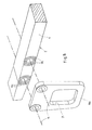
- in perspektivischer, teilweise geschnittener Darstellung eine vierte Ausführungsform einer Achsaufhängung;
- Fig. 8
- in einer Explosionsdarstellung Einzelheiten der Achsaufhängung nach Figur 7;
- Fig. 9
- in Seitenansicht eine fünfte Ausführungsform einer Achsaufhängung;
- Fig. 10
- in Seitenansicht eine sechste Ausführungsform einer Achsaufhängung;
- Fig. 11
- in Seitenansicht eine siebte Ausführungsform einer Achsaufhängung;
- Fig. 12
- in Seitenansicht eine achte Ausführungsform einer Achsaufhängung und
- Fig. 13
- die Achsaufhängung nach Fig. 12 in einer Draufsicht.
- 1
- Achskörper
- 2
- Lenkerfeder
- 3
- Auge
- 4
- Konsole
- 5
- Luftfeder
- 6
- Längsträger
- 7
- Verbindungsflansch
- 8
- Außenseite
- 9
- Seitenfläche der Lenkerfeder
- 10
- Flansch
- 11
- Bolzen
- 12a
- Seite des Achskörpers
- 12b
- Seite des Achskörpers
- 13
- Schweißnaht
- 14
- vorderes Teil der Lenkerfeder
- 15
- hinteres Teil der Lenkerfeder
- 16
- Abbiegung
- 17
- hintere Abschlußfläche
- 18
- Schraube
- 19
- Längsschlitz
- 19a
- Seitenflansch
- 19b
- Seitenflansch
- 19c
- Vorsprünge
- 20
- Verbindungselement
- 21
- Ausnehmung
- 22
- Stützfläche
- 23
- Querstrebe
- 24
- Seitenwand
- 25
- Unterseite
- 26
- Oberseite
- 27
- Fahrtrichtung
- 28
- Ausnehmung
- 29
- Zapfen
- 30
- Stoßdämpfer
- 31
- Auge
- 32
- Schraube
- 33
- Klaue
- 34
- Schraubbolzen
- 35
- Schenkel
- b
- Breite
Claims (17)
- Achsaufhängung für eine luftgefederte Fahrzeugachse, deren Achskörper an zu beiden Seiten des Fahrzeugs angeordneten Lenkerfedern (2) befestigt ist, deren eines Ende, vorzugsweise über eine Konsole (4) verschwenkbar am Fahrzeugrahmen (6) angelenkt ist und deren anderes Ende über eine Luftfeder (5) gegenüber dem Fahrzeugrahmen (6) abgestützt ist,
dadurch gekennzeichnet, daß Achskörper (1) und Lenkerfeder (2) über mindestens einen Bolzen (11, 34) miteinander verbunden sind, der zugleich den Achskörper (1) oder starr daran befestigte Teile und eine Bohrung der Lenkerfeder (2) durchsetzt. - Achsaufhängung nach Anspruch 1, dadurch gekennzeichnet, daß die Achse des Bolzens (11, 34) in der durch die Lenkerfedern (2) und den Achskörper (1) aufgespannten oder in einer dazu parallelen Ebene angeordnet ist.
- Achsaufhängung nach Anspruch 1 oder Anspruch 2, dadurch gekennzeichnet, daß sich die Achse des Bolzens (11) parallel zu dem Achskörper (1) erstreckt.
- Achsaufhängung nach einem der Ansprüche 1 bis 3, dadurch gekennzeichnet, daß der Bolzen (11, 34) ein mit mindestens einer Gewindemutter gesicherter Schraubbolzen ist.
- Achsaufhängung nach einem der Ansprüche 1 bis 4, dadurch gekennzeichnet, daß der Achskörper (1) mit mindestens einem starr daran befestigten Verbindungselement versehen ist, welches eine sich quer zu dem Achskörper (1) erstreckende Seitenwand (10; 19a, 19b; 24) aufweist, an der sich die Lenkerfeder (2) seitlich abstützt, und daß der Bolzen (11) zugleich die Seitenwand (10; 19a, 19b; 24) des Verbindungselements und eine Querbohrung der Lenkerfeder (2) durchsetzt.
- Achsaufhängung nach Anspruch 5, dadurch gekennzeichnet, daß das Verbindungselement ein mit dem Achskörper (1) verschweißter und mit mindestens einem Loch für den Durchtritt des Bolzens (11) versehener Flansch (10; 19a, 19b; 24) ist.
- Achsaufhängung nach Anspruch 6, dadurch gekennzeichnet, daß der Flansch (10; 19a, 19b; 24) den Achskörper (1) an zwei einander abgewandten Seiten (12a, 12b) mit einer an die Querschnittskontur des Achskörpers (1) angeglichenen Ausnehmung (21) umgreift, und daß sich die Flansch (10; 19a, 19b; 24) und Achskörper (1) verbindende Schweißnaht (13) entlang der Ausnehmung (21) erstreckt.
- Achsaufhängung nach einem der Ansprüche 5 bis 7, dadurch gekennzeichnet, daß der Achskörper (1) mit insgesamt zwei Flanschen (19a, 19b) als Verbindungselemente versehen ist, zwischen deren einander zugewandten Seitenwänden die Lenkerfeder (2) hindurchgeführt ist.
- Achsaufhängung nach Anspruch 8, gekennzeichnet durch eine den Achskörper (1) vollständig umgebende Ausnehmung (21) in jedem der beiden Flansche (19a, 19b),
- Achsaufhängung nach einem der Ansprüche 5 bis 9, dadurch gekennzeichnet, daß die Lenkerfeder (2) um die Öffnung der Querbohrung für den Bolzen (11) herum mit vorzugsweise ringförmig angeordneten Vorsprüngen (19c) versehen ist, an denen sich der Flansch (19a, 19b) abstützt.
- Achsaufhängung nach einem der Ansprüche 5 bis 7, dadurch gekennzeichnet, daß das Verbindungselement (20) mit einer zwischen dem Achskörper (1) und der Lenkerfeder (2) angeordneten Stützfläche (22) versehen ist, an der sich die Lenkerfeder (2) mit einer ihrer beiden horizontalen Flachseiten (25) abstützt.
- Achsaufhängung nach Anspruch 11, dadurch gekennzeichnet, daß Stützfläche (22) und Seitenwand (24) rechtwinklig zueinander liegen.
- Achsaufhängung nach Anspruch 11 oder Anspruch 12, dadurch gekennzeichnet, daß das Verbindungselement (20) mit einer starr an der Seitenwand (24) befestigten Querstrebe (23) versehen ist, an der sich die Lenkerfeder (2) mit der anderen ihrer beiden horizontalen Flachseiten (26) abstützt.
- Achsaufhängung nach Anspruch 13, dadurch gekennzeichnet, daß sich die Querstrebe (23) in Fahrtrichtung (27) weiter vorne an dem Verbindungselement' (20) befindet, als der die Lenkerfeder (2) durchdringende Bolzen (11).
- Achsaufhängung nach einem der Ansprüche 5 bis 11, dadurch gekennzeichnet, daß das Verbindungselement mit zwei Bolzen (11) zwei hintereinander in der Lenkerfeder angeordnete Querbohrungen durchdringt.
- Achsaufhängung nach einem der vorangehenden Ansprüche, gekennzeichnet durch eine in Längsrichtung zweigeteilte Lenkerfeder, wobei sich die von dem Bolzen (11) durchsetzte Bohrung in dem vorderen Teil (14) der Lenkerfeder befindet, und sich an dem hinteren Teil (15) der Lenkerfeder die Luftfeder (5) abstützt.
- Achsaufhängung nach einem der Ansprüche 5 bis 16, dadurch gekennzeichnet, daß an dem Verbindungselement (20) ein Anlenkpunkt (29) für einen Stoßdämpfer (30) befestigt ist.
Applications Claiming Priority (2)
| Application Number | Priority Date | Filing Date | Title |
|---|---|---|---|
| DE10018315 | 2000-04-13 | ||
| DE10018315A DE10018315A1 (de) | 2000-04-13 | 2000-04-13 | Achsaufhängung für eine luftgefederte Fahrzeugachse |
Publications (2)
| Publication Number | Publication Date |
|---|---|
| EP1145878A2 true EP1145878A2 (de) | 2001-10-17 |
| EP1145878A3 EP1145878A3 (de) | 2003-10-29 |
Family
ID=7638600
Family Applications (1)
| Application Number | Title | Priority Date | Filing Date |
|---|---|---|---|
| EP01108573A Withdrawn EP1145878A3 (de) | 2000-04-13 | 2001-04-05 | Achsaufhängung für eine luftgefederte Fahrzeugachse |
Country Status (2)
| Country | Link |
|---|---|
| EP (1) | EP1145878A3 (de) |
| DE (1) | DE10018315A1 (de) |
Cited By (9)
| Publication number | Priority date | Publication date | Assignee | Title |
|---|---|---|---|---|
| NL1026947C2 (nl) * | 2004-09-01 | 2006-03-02 | Weweler Nv | Veerarm met geplet eindgedeelte. |
| EP1478529A4 (de) * | 2002-02-01 | 2007-01-03 | Holland Group Inc | Längslenkeraufhängung mit optimiertem arm |
| WO2010066232A1 (de) * | 2008-12-09 | 2010-06-17 | Bpw Bergische Achsen Kg | Achsaufhängung für eine fahrzeugachse |
| EP2137016A4 (de) * | 2007-03-29 | 2010-12-22 | Hendrickson Usa Llc | Führungs- und lenkungsarmaufhängungen mit einem vollständig integrierten arm |
| US8029008B2 (en) | 2005-04-27 | 2011-10-04 | Hendrickson Usa, L.L.C. | Vehicle suspensions having leaf springs and alternative clamp groups |
| CN102275479A (zh) * | 2011-06-07 | 2011-12-14 | 佛山市永力泰车轴有限公司 | 一种汽车空气悬架系统中的导向臂 |
| US8177246B2 (en) | 2005-04-27 | 2012-05-15 | Hendrickson Usa, L.L.C. | Axle seat for vehicle suspensions |
| WO2017100452A1 (en) * | 2015-12-10 | 2017-06-15 | Hendrickson Usa, L.L.C. | Pivotal connection for heavy-duty vehicle suspension assembly |
| US20190118601A1 (en) * | 2017-10-20 | 2019-04-25 | Ford Global Technologies, Llc | Leaf spring suspension |
Families Citing this family (4)
| Publication number | Priority date | Publication date | Assignee | Title |
|---|---|---|---|---|
| US6676143B2 (en) * | 2001-09-28 | 2004-01-13 | Meritor Heavy Vehicle Technology, Llc | Modular suspension arm assembly |
| DE102016209691A1 (de) | 2016-06-02 | 2017-12-07 | Ford Global Technologies, Llc | Zweiteilige Radaufhängungseinheit |
| DE202016103196U1 (de) | 2016-06-02 | 2016-07-06 | Ford Global Technologies, Llc | Zweiteilige Radaufhängungseinheit |
| DE102016209689B4 (de) | 2016-06-02 | 2024-05-29 | Ford Global Technologies, Llc | Zweiteilige Radaufhängungseinheit |
Family Cites Families (9)
| Publication number | Priority date | Publication date | Assignee | Title |
|---|---|---|---|---|
| DE417805C (de) * | 1925-08-18 | Traugott Onnasch | Abfederung fuer Kraftfahrzeuge | |
| US2971772A (en) * | 1959-03-18 | 1961-02-14 | Fruehauf Trailer Co | Wheel suspension and cantilever spring bracing therefor for trailer |
| GB980372A (en) * | 1962-03-20 | 1965-01-13 | Daimler Benz Ag | Improvements relating to spring arrangements |
| US3332701A (en) * | 1965-06-10 | 1967-07-25 | Neway Equipment Co | Suspension for automotive vehicles |
| US3510149A (en) * | 1967-10-04 | 1970-05-05 | John E Raidel | Adjustable air suspension |
| US4134604A (en) * | 1977-07-07 | 1979-01-16 | Jackson Lift Co., Inc. | Vehicle suspension |
| US5112078A (en) * | 1990-12-21 | 1992-05-12 | Neway Corp. | Axle mounting assembly |
| US5354091A (en) * | 1992-09-01 | 1994-10-11 | The Binkley Company | Wheeled vehicle suspensions |
| ES2162597B1 (es) * | 2000-03-14 | 2002-06-01 | Fundiciones De Vera S A | Sistema de amarre de ballesta a eje de vehiculo y ballesta para eje de vehiculo. |
-
2000
- 2000-04-13 DE DE10018315A patent/DE10018315A1/de not_active Withdrawn
-
2001
- 2001-04-05 EP EP01108573A patent/EP1145878A3/de not_active Withdrawn
Cited By (17)
| Publication number | Priority date | Publication date | Assignee | Title |
|---|---|---|---|---|
| EP1478529A4 (de) * | 2002-02-01 | 2007-01-03 | Holland Group Inc | Längslenkeraufhängung mit optimiertem arm |
| EP1632370A1 (de) * | 2004-09-01 | 2006-03-08 | Weweler Nederland B.V. | Aufhängungslenker mit abgeflachtem Eindteil |
| NL1026947C2 (nl) * | 2004-09-01 | 2006-03-02 | Weweler Nv | Veerarm met geplet eindgedeelte. |
| US8029008B2 (en) | 2005-04-27 | 2011-10-04 | Hendrickson Usa, L.L.C. | Vehicle suspensions having leaf springs and alternative clamp groups |
| US8177246B2 (en) | 2005-04-27 | 2012-05-15 | Hendrickson Usa, L.L.C. | Axle seat for vehicle suspensions |
| EP2137016A4 (de) * | 2007-03-29 | 2010-12-22 | Hendrickson Usa Llc | Führungs- und lenkungsarmaufhängungen mit einem vollständig integrierten arm |
| US8038163B2 (en) | 2007-03-29 | 2011-10-18 | Hendrickson Usa, L.L.C. | Leading and trailing arm suspensions having a fully integrated arm |
| CN101687453B (zh) * | 2007-03-29 | 2012-08-08 | 亨德里克森美国有限责任公司 | 具有完全一体臂的引导臂和拖臂悬架 |
| AU2008232774B2 (en) * | 2007-03-29 | 2014-03-13 | Hendrickson Usa, L.L.C. | Leading and trailing arm suspensions having a fully integrated arm |
| WO2010066232A1 (de) * | 2008-12-09 | 2010-06-17 | Bpw Bergische Achsen Kg | Achsaufhängung für eine fahrzeugachse |
| EP2607115A1 (de) * | 2008-12-09 | 2013-06-26 | BPW Bergische Achsen KG | Achsaufhängung für eine Fahrzeugachse |
| CN102245411B (zh) * | 2008-12-09 | 2013-12-25 | Bpw矿用轴公司 | 用于车轴的轴悬挂装置 |
| CN102275479A (zh) * | 2011-06-07 | 2011-12-14 | 佛山市永力泰车轴有限公司 | 一种汽车空气悬架系统中的导向臂 |
| WO2017100452A1 (en) * | 2015-12-10 | 2017-06-15 | Hendrickson Usa, L.L.C. | Pivotal connection for heavy-duty vehicle suspension assembly |
| US10017020B2 (en) | 2015-12-10 | 2018-07-10 | Hendrickson Usa, L.L.C. | Pivotal connection for heavy-duty vehicle suspension assembly |
| US20190118601A1 (en) * | 2017-10-20 | 2019-04-25 | Ford Global Technologies, Llc | Leaf spring suspension |
| US10744835B2 (en) * | 2017-10-20 | 2020-08-18 | Ford Global Technologies, Llc | Leaf spring suspension |
Also Published As
| Publication number | Publication date |
|---|---|
| EP1145878A3 (de) | 2003-10-29 |
| DE10018315A1 (de) | 2001-10-25 |
Similar Documents
| Publication | Publication Date | Title |
|---|---|---|
| EP2355988B2 (de) | Achsaufhängung für eine fahrzeugachse | |
| DE19536460A1 (de) | Teilrahmenbaugruppe für ein Fahrzeug | |
| EP1145878A2 (de) | Achsaufhängung für eine luftgefederte Fahrzeugachse | |
| DE202015008095U1 (de) | Tandemachse | |
| DE19624242A1 (de) | Vorrichtung zur Querführung einer Starrachse eines Kraftfahrzeuges | |
| DE102009030633A1 (de) | Achseinbindung für gefederte Fahrzeugachsen sowie Platte zum Einbinden einer Fahrzeugachse | |
| DE69211143T2 (de) | Konstruktion einer achse für lastfahrzeug | |
| DE69225225T2 (de) | Fahrzeugaufhängung | |
| EP1057716B1 (de) | Achskonstruktion für Nutzfahrzeuge, Nutzfahrzeuganhänger und -auflieger | |
| EP2772372B1 (de) | Fahrwerk für ein nutzfahrzeug und achskörper | |
| EP2502809A1 (de) | Anhebevorrichtung für einen Achslenker sowie Achslenker | |
| EP0940319A2 (de) | Fahrgestell eines schweren Nutzfahrzeuges | |
| EP1777085B1 (de) | Achsaufhängung für eine längslenkergeführte Fahrzeugachse | |
| EP1574366B1 (de) | Achsaufhängung und Federplatte für eine Achsanbindung | |
| DE10206017A1 (de) | Fahrzeugachse | |
| EP2647512B1 (de) | Achslenker | |
| EP0940324A1 (de) | Fahrgestell eines schweren Nutzfahrzeuges | |
| EP0940325A1 (de) | Fahrgestell eines schweren Nutzfahrzeuges | |
| DE10054839A1 (de) | Befestigung einer Fahrzeugachse an einer Achsaufhängung | |
| DE102018006572B4 (de) | Fahrzeugaufhängungsanordnung für mindestens eine Radachse | |
| DE102017201747B3 (de) | Einzelradaufhängung eines Fahrzeuges | |
| EP0940321B1 (de) | Fahrgestell eines schweren Nutzfahrzeuges | |
| DE10011559B4 (de) | Fahrgestell für einen Kraftfahrzeuganhänger, vorzugsweise für einen Wohnanhänger | |
| EP2332751B1 (de) | Lkw-Rohrtraverse mit geteiltem Rohr | |
| EP3501952B1 (de) | Toleranzausgleich bei montageteilen in baugruppen durch elastische elemente |
Legal Events
| Date | Code | Title | Description |
|---|---|---|---|
| PUAI | Public reference made under article 153(3) epc to a published international application that has entered the european phase |
Free format text: ORIGINAL CODE: 0009012 |
|
| AK | Designated contracting states |
Kind code of ref document: A2 Designated state(s): AT BE CH CY DE DK ES FI FR GB GR IE IT LI LU MC NL PT SE TR |
|
| AX | Request for extension of the european patent |
Free format text: AL;LT;LV;MK;RO;SI |
|
| PUAL | Search report despatched |
Free format text: ORIGINAL CODE: 0009013 |
|
| AK | Designated contracting states |
Kind code of ref document: A3 Designated state(s): AT BE CH CY DE DK ES FI FR GB GR IE IT LI LU MC NL PT SE TR |
|
| AX | Request for extension of the european patent |
Extension state: AL LT LV MK RO SI |
|
| AKX | Designation fees paid | ||
| REG | Reference to a national code |
Ref country code: DE Ref legal event code: 8566 |
|
| STAA | Information on the status of an ep patent application or granted ep patent |
Free format text: STATUS: THE APPLICATION IS DEEMED TO BE WITHDRAWN |
|
| 18D | Application deemed to be withdrawn |
Effective date: 20040504 |