EP1145850A1 - Folding unit for a web printing press - Google Patents
Folding unit for a web printing press Download PDFInfo
- Publication number
- EP1145850A1 EP1145850A1 EP01108801A EP01108801A EP1145850A1 EP 1145850 A1 EP1145850 A1 EP 1145850A1 EP 01108801 A EP01108801 A EP 01108801A EP 01108801 A EP01108801 A EP 01108801A EP 1145850 A1 EP1145850 A1 EP 1145850A1
- Authority
- EP
- European Patent Office
- Prior art keywords
- folding
- former
- folding unit
- unit according
- products
- Prior art date
- Legal status (The legal status is an assumption and is not a legal conclusion. Google has not performed a legal analysis and makes no representation as to the accuracy of the status listed.)
- Granted
Links
Images

Classifications
-
- B—PERFORMING OPERATIONS; TRANSPORTING
- B65—CONVEYING; PACKING; STORING; HANDLING THIN OR FILAMENTARY MATERIAL
- B65H—HANDLING THIN OR FILAMENTARY MATERIAL, e.g. SHEETS, WEBS, CABLES
- B65H45/00—Folding thin material
- B65H45/12—Folding articles or webs with application of pressure to define or form crease lines
- B65H45/22—Longitudinal folders, i.e. for folding moving sheet material parallel to the direction of movement
- B65H45/221—Longitudinal folders, i.e. for folding moving sheet material parallel to the direction of movement incorporating folding triangles
- B65H45/225—Arrangements of folding triangles
-
- B—PERFORMING OPERATIONS; TRANSPORTING
- B41—PRINTING; LINING MACHINES; TYPEWRITERS; STAMPS
- B41F—PRINTING MACHINES OR PRESSES
- B41F13/00—Common details of rotary presses or machines
- B41F13/54—Auxiliary folding, cutting, collecting or depositing of sheets or webs
- B41F13/56—Folding or cutting
- B41F13/58—Folding or cutting lengthwise
-
- B—PERFORMING OPERATIONS; TRANSPORTING
- B65—CONVEYING; PACKING; STORING; HANDLING THIN OR FILAMENTARY MATERIAL
- B65H—HANDLING THIN OR FILAMENTARY MATERIAL, e.g. SHEETS, WEBS, CABLES
- B65H45/00—Folding thin material
- B65H45/12—Folding articles or webs with application of pressure to define or form crease lines
- B65H45/28—Folding in combination with cutting
Definitions
- the invention relates to a folder for a web-fed rotary printing press the preamble of claim 1.
- Illustration folders are usually equipped with a former, feed rollers, Draw rollers and a cylinder group equipped to fold products with a Longitudinal fold and one or two transverse folds.
- a folder is in the Lithoman brochure, illustration web offset, page 20, MAN Roland Druckmaschinen AG, Augsburg, 2.97.
- the cylinder group contains one Knife cylinder, a puncture and folding knife cylinder, one Folding jaw cylinder and, if necessary, a gripper and folding knife cylinder.
- One or two additional 3rd folding devices allow an additional second Longitudinal fold.
- For a printing press simply wide and simple in scope (i.e. 4 A4 pages in width and 2 pages in circumference), so products with 8 pages A3, 16 pages A4, 16 pages A5 double-sided and 12 pages delta fold or 24 pages of delta fold plus second longitudinal fold.
- the desire is to add additional 4- or 8-page products (so-called envelopes). This can be done with a so-called Cutting unit reached in connection with an additional former become.
- Folding units with such an additional former are mentioned in the Brochure, shown on page 19.
- the well-known fold types 2 x 8 can be used Generate A4 pages or 4 x 4 A4 pages when using two formers.
- the used spelling of z. B. 2 x 8 pages A4 for two products with 8 pages each A4 is retained in the following.
- the same product extension can be with a complete additional so-called double-former folding unit realize.
- the extension variants mentioned have some disadvantages. So condition additional tape deliveries, so-called disposal lines. Also strikes an additional space requirement to beech. This is how the double hopper folder is located in the Extension of the machine. There are also increased investment costs. Finally, the folding unit variants mentioned are in combination with 1.5 fold wide machines, e.g. B. 24-page machines, or all machines with through 3 divisible widths uneconomical. For example, with a 24-page press 4 x 4 A4 pages can only be produced with a 2/3 wide web.
- the invention has for its object to provide a folder that with low technical effort and a high production variety allowed.
- the object is achieved with a generic folding unit with the Means of the characterizing part of claim 1 solved.
- the Folding unit according to the invention enables to those described Production variants in addition to other production options. Also thanks to that Presence of three funnels leading z. B. 6 strands over one Hopper avoidable and thus good folding accuracy and quality can be achieved.
- the folder is inexpensive to produce and is characterized by a takes up little space. It can be economically spread from one 6 pages Web produce 4-sided products, e.g. B. when printing with a 24-page press 6 x 4 pages and 12 x 4 pages when printing with a 48-page press.
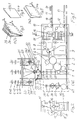
- the folding unit shown in FIG. 1 contains a knife cylinder 1, a Puncture and folding knife cylinder 2 and a folding jaw cylinder 3.
- a puncture and folding knife cylinder 2 a stapler 4
- Folding jaw cylinder 3 is a gripper and folding knife cylinder 5 for executing a assigned second cross fold.
- a ribbon cable 6 leads from the jaw cylinder 3 to a copy switch 7. From the latter, ribbon lines 8, 9 go to a first paddle wheel 10 in addition first band line 11 or second paddle wheel 12 together with second band line 13 from. There are up to two in the belt deliveries 11 and 13, respectively Item separators 14 arranged. They continue to happen Band lines 8 and 9 each have a first and second 3rd folding device 15, 16, respectively each a third paddle wheel 17 and a third band line 18 and a Connect the fourth paddle wheel 19 and a fourth ribbon line 20 (FIG. 2).
- the puncture and folding knife cylinder 2 and Folding cylinder 3 containing cylinder is a first former 21 arranged, in addition to that on both sides a second or third Folder 22, 23 is positioned.
- first former 21 On the train path from the first former 21 to the puncturing and folding knife cylinder 2 are inlet rollers 24, pull rollers 25, a transverse perforation device 26 and a longitudinal perforation device 27 arranged.
- the second and third former 22, 23 close also inlet rollers 24.1, 24.2 and guide rollers 28 around which these funnels 22, 23 leaving strands 29, 30 also via the Cross perforation device 26, the longitudinal perforation device 27 and Draw rollers 25 to the puncture and folding knife cylinder 2.
- To the Funnels 22, 23 leaving strands 29, 30 are each one Longitudinal gluing device 31, 32 adjustable.
- the folding formers 21, 22, 23 are advantageous in their longitudinal direction, i. H. in the direction of the strands running onto it, movable.
- the first former 21 is advantageously 4 pages wide, to carry out the usual production on it can.
- the second former 22 and the third former 23 are advantageously 2 Wide sides, they are ready to part compared to the first former 21 executed, d. that is, they are only part of the width of the first former 21 on.
- the second former 22 can also be the full width of the first Have former 21.
- the web (or webs) printed by a printing machine, not shown is cut into strands and guided to the formers 21, 22, 23.
- Fig. 1 are over the funnels 21 to 23 examples of these strands to be fed with different locations.
- 6x6 pages can be fed become.
- each strand 29, 30 and 33 has two sides and contains a partial web 1 page wide.
- the one in the middle to the center line Strange line lying a 2-page wide web and that to the center line reaching dash represents a 1 page wide web.
- the strands with 6 x 8 pages z. B.
- the processing of 6 x 4 pages is explained below.
- the three each 2 sides wide strands 29, 30, 33 are cut according to the longitudinal section of a web a 24-page printing machine with a simple scope (i.e. two standing pages 6 pages in width) was printed.
- Strands 29, 33, 30 are guided over the former 22, 21, 23 and folded lengthways.
- the longitudinally folded strands 29, 33, 30 then pass through the Inlet rollers 24.1, 24 and 24.2.
- About the guide rollers 28 are the Strands 29 and 30 placed on strand 33.
- the superimposed strands 29, 33 and 30 pass through drawing rollers 25 and can pass through the Cross perforation device 26 and the longitudinal perforation device 27 with a Cross perforation and a longitudinal perforation.
- the products 34 can be externally trimmed in which the cross fold and optionally also the area of the punctures 35 is cut off.
- This Trim is symbolically indicated in Fig. 3.
- the Trimming can be done, for example, with a familiar to the expert Rotary cutter done. Such a cutter cuts a product stream with rotating knives.
- a rotary cutter 42 is shown schematically in FIG. 6. In the present case, the product flow is initially 90 ° in its direction redirected. This is done by means of a connecting to the ribbon cable 11 Band line 11.1 with a transport direction rotated by 90 ° to the former.
- the Products 34 can also be provided with a third fold (second longitudinal fold).
- the Delivery of these folded products takes place via the third paddle wheel 17 on the third Tape line 18 and the fourth paddle wheel 19 on the fourth tape line 20.
- the fourth ribbon cable 20 are stored (Fig. 2).
- the described three form former 21 to 23 folding unit containing can be supplemented with a cutting unit 36.
- a cutting unit 36 contains two pairs of pull rollers 37, one Cutting cylinder pair 38, a ribbon line 39, a fifth paddle wheel 40 and one fifth ribbon line 41.
- the strand 29.1 leaving the second former 22 becomes after passing through the inlet rollers 24.1 and a pair of pull rollers 25 to the Cutting unit 36 out. There it is closed by further pairs of draw rollers 37 directed to the pair of cutting cylinders 38, where it cut into products of 2 x 4 pages becomes. These products are accelerated by the ribbon line 39 and into the fifth paddle wheel 40 conveyed that the products on the fifth ribbon line 41st interprets.
- the strands 33, 30 longitudinally folded by the formers 21 and 23 become the knife cylinder 1, puncture and folding knife cylinder 2 and Folding jaw cylinder 3 guided.
- the former 22 and 23 can so far that the strands 33 and 30 next to each other in the Run in cylinder groups 1 to 3.
- the processing and display of the from the Strands 33 and 30 produced products 34.1 on the first and / or second Strip line 11, 13 takes place in the manner already described. There can be three Copy streams of 2 x 4 pages each with different print images can be generated. The delivery takes place on the ribbon lines 11, 13 and 41.
- the invention was based on standing production (standing format) described. It is also with horizontal production (horizontal format) applicable, i.e. with the sides lying transversely to the running direction of the web.
Abstract
Description
Die Erfindung betrifft ein Falzwerk für eine Rollenrotationsdruckmaschine nach
dem Oberbegriff des Patentanspruchs 1.The invention relates to a folder for a web-fed rotary printing press
the preamble of
Illustrationsfalzwerke sind in der Regel mit einem Falztrichter, Einlaufwalzen,
Zugwalzen und einer Zylindergruppe ausgestattet, um Falzprodukte mit einem
Längsfalz und einem oder zwei Querfalzen zu erzeugen. Ein derartiges Falzwerk
ist im Prospekt Lithoman, Illustrations-Rollenoffset, Seite 20, MAN Roland
Druckmaschinen AG, Augsburg, 2.97, gezeigt. Die Zylindergruppe enthält einen
Messerzylinder, einen Punktur- und Falzmesserzylinder, einen
Falzklappenzylinder und ggf. einen Greifer- und Falzmesserzylinder. Eine oder
zwei weitere 3.Falzeinrichtungen ermöglichen einen zusätzlichen zweiten
Längsfalz. Bei einer Druckmaschine, einfach breit und einfach im Umfang (d. h. 4
Seiten A4 stehend in der Breite und 2 Seiten im Umfang), können so Produkte mit
8 Seiten A3, 16 Seiten A4, 16 Seiten A5 Doppelnutzen und 12 Seiten Deltafalz
bzw. 24 Seiten Deltafalz plus zweiter Längsfalz erzeugt werden.Illustration folders are usually equipped with a former, feed rollers,
Draw rollers and a cylinder group equipped to fold products with a
Longitudinal fold and one or two transverse folds. Such a folder
is in the Lithoman brochure, illustration web offset,
Der Wunsch besteht darin, weitere zusätzliche 4- oder 8-Seiten-Produkte
(sogenannte Umschläge) zu erzeugen. Dies kann mit einem sogenannten
Schneidaggregat in Verbindung mit einem zusätzlichen Falztrichter erreicht
werden. Falzwerke mit einem solchen zusätzlichen Falztrichter sind im genannten
Prospekt, auf Seite 19 gezeigt. Es lassen sich so zu den bekannten Falzarten 2 x 8
Seiten A4 oder bei Einsatz von zwei Falztrichtern 4 x 4 Seiten A4 erzeugen. Die
benutzte Schreibweise von z. B. 2 x 8 Seiten A4 für zwei Produkte mit je 8 Seiten
DIN A4 wird im folgenden beibehalten. Die gleiche Produkterweiterung lässt sich
mit einem kompletten zusätzlichen sogenannten Doppeltrichterfalzwerk
realisieren.The desire is to add additional 4- or 8-page products
(so-called envelopes). This can be done with a so-called
Cutting unit reached in connection with an additional former
become. Folding units with such an additional former are mentioned in the
Brochure, shown on
Die genannten Erweiterungsvarianten weisen einige Nachteile auf. So bedingen sie zusätzliche Bandauslagen, sogenannte Entsorgungslinien. Außerdem schlägt ein zusätzlicher Platzbedarf zu Buche. So steht das Doppeltrichterfalzwerk in der Verlängerung der Maschine. Außerdem fallen erhöhte Investitionskosten an. Schließlich sind die genannten Falzwerkvarianten in Kombination mit 1,5 fach breiten Maschinen, z. B. 24-Seiten-Maschinen, bzw. allen Maschinen mit durch 3 teilbaren Breiten unwirtschaftlich. Bei einer 24-Seiten-Maschine beispielsweise sind 4 x 4 Seiten A4 nur mit einer 2/3 breiten Bahn herstellbar.The extension variants mentioned have some disadvantages. So condition additional tape deliveries, so-called disposal lines. Also strikes an additional space requirement to beech. This is how the double hopper folder is located in the Extension of the machine. There are also increased investment costs. Finally, the folding unit variants mentioned are in combination with 1.5 fold wide machines, e.g. B. 24-page machines, or all machines with through 3 divisible widths uneconomical. For example, with a 24-page press 4 x 4 A4 pages can only be produced with a 2/3 wide web.
Der Erfindung liegt die Aufgabe zugrunde, ein Falzwerk zu schaffen, das mit geringem technischem Aufwand erstellbar ist und eine hohe Produktionsvielfalt erlaubt.The invention has for its object to provide a folder that with low technical effort and a high production variety allowed.
Die Aufgabe wird erfindungsgemäß bei einem gattungsgemäßen Falzwerk mit den
Mitteln des kennzeichnenden Teils des Patentanspruchs 1 gelöst. Das
erfindungsgemäße Falzwerk ermöglicht zu den beschriebenen
Produktionsvarianten hinaus weitere Produktionsmöglichkeiten. Auch ist dank dem
Vorhandensein von drei Trichtern das Führen von z. B. 6 Strängen über einen
Trichter vermeidbar und somit eine gute Falzgenauigkeit und -qualität erzielbar.
Außerdem ist das Falzwerk kostengünstig erstellbar und zeichnet sich durch einen
geringen Platzbedarf aus. Es lassen sich wirtschaftlich aus einer 6 Seiten breiten
Bahn 4-seitige Produkte erzeugen, z. B. beim Druck mit einer 24-Seiten-Maschine
6 x 4 Seiten und beim Druck mit einer 48-Seiten-Maschine 12 x 4 Seiten.The object is achieved with a generic folding unit with the
Means of the characterizing part of
Weitere Vorteile und Merkmale ergeben sich aus den Unteransprüchen in Verbindung mit den Zeichnungen.Further advantages and features emerge from the subclaims in Connection with the drawings.
Die Erfindung soll nachfolgend an einem Ausführungsbeispiel näher erläutert werden. In den zugehörigen Zeichnungen zeigt schematisch:
- Fig. 1:
- ein Falzwerk mit drei Falztrichtern
- Fig. 2:
- den Schnitt II-
II nach Figur 1 - Fig. 3:
- ein 24-seitiges Produkt
- Fig. 4:
- ein 4-seitiges Produkt der Produktion 6x4 Seiten
- Fig. 5:
- ein 8-seitiges Produkt
- Fig. 6:
- den Beschnitt eines Produktstromes.
- Fig. 1:
- a folder with three formers
- Fig. 2:
- the section II-II of Figure 1
- Fig. 3:
- a 24-page product
- Fig. 4:
- a 4-page product of production 6x4 pages
- Fig. 5:
- an 8-page product
- Fig. 6:
- the trimming of a product stream.
Das in Figur 1 dargestellte Falzwerk enthält einen Messerzylinder 1, einen
Punktur- und Falzmesserzylinder 2 sowie einen Falzklappenzylinder 3. Wahlweise
ist dem Punktur- und Falzmesserzylinder 2 ein Heftapparat 4 und dem
Falzklappenzylinder 3 ein Greifer- und Falzmesserzylinder 5 zur Ausführung eines
zweiten Querfalzes zugeordnet.The folding unit shown in FIG. 1 contains a
Vom Falzklappenzylinder 3 führt eine Bandleitung 6 zu einer Exemplarweiche 7.
Von letzterer gehen Bandleitungen 8, 9 zu einem ersten Schaufelrad 10 nebst
erster Bandleitung 11 bzw. zweitem Schaufelrad 12 nebst zweiter Bandleitung 13
ab. In den Bandauslagen 11 bzw. 13 sind wahlweise bis zu zwei
Exemplartrennvorrichtungen 14 angeordnet. Weiterhin passieren die
Bandleitungen 8 und 9 jeweils eine erste bzw. zweite 3.Falz-Vorrichtung 15, 16, an
die sich jeweils ein drittes Schaufelrad 17 und eine dritte Bandleitung 18 bzw. ein
viertes Schaufelrad 19 und eine vierte Bandleitung 20 anschließen (Fig. 2).A
Über der den Messerzylinder 1, den Punktur- und Falzmesserzylinder 2 und den
Falzklappenzylinder 3 enthaltenden Zylindergruppe ist ein erster Falztrichter 21
angeordnet, neben dem zu beiden Seiten jeweils ein zweiter bzw. dritter
Falztrichter 22, 23 positioniert ist. Auf dem Bahnweg vom ersten Falztrichter 21
zum Punktur- und Falzmesserzylinder 2 sind Einlaufwalzen 24, Zugwalzen 25,
eine Querperforationseinrichtung 26 und eine Längsperforationseinrichtung 27
angeordnet. An den zweiten und dritten Falztrichter 22, 23 schließen sich
ebenfalls Einlaufwalzen 24.1, 24.2 sowie Leitwalzen 28 an, um die diese Trichter
22, 23 verlassenden Stränge 29, 30 ebenfalls über die
Querperforationseinrichtung 26, die Längsperforationseinrichtung 27 und
Zugwalzen 25 zu dem Punktur- und Falzmesserzylinder 2 zu leiten. An die die
Trichter 22, 23 verlassenden Stränge 29, 30 ist jeweils eine
Längsbeleimvorrichtung 31, 32 anstellbar. Above the
Die Falztrichter 21, 22, 23 sind vorteilhaft in ihrer Längsrichtung, d. h. in Richtung
der auf sie auflaufenden Stränge, verschiebbar. Der erste Falztrichter 21 ist
vorteilhaft 4 Seiten breit ausgeführt, um auf ihm übliche Produktion ausführen zu
können. Der zweite Falztrichter 22 und der dritte Falztrichter 23 sind vorteilhaft 2
Seiten breit ausgeführt, sie sind gegenüber dem ersten Falztrichter 21 teilbereit
ausgeführt, d. h., sie weisen nur einen Teil der Breite des ersten Falztrichters 21
auf. Der zweite Falztrichter 22 kann jedoch auch die volle Breite des ersten
Falztrichters 21 aufweisen.The
Die von einer nicht dargestellten Druckmaschine bedruckte Bahn (bzw. Bahnen)
wird in Stränge geschnitten und auf die Falztrichter 21, 22, 23 geführt. In Fig. 1
sind über den Trichtern 21 bis 23 Beispiele für diesen zuzuführende Stränge mit
verschiedenen Lagen angegeben. So können beispielsweise 6x6 Seiten zugeführt
werden. Darunter ist zu verstehen, dass jeder Strang 29, 30 und 33 eine 2 Seiten
und eine 1 Seite breite Teilbahn enthält. Weiterhin sind auf dem Umfang eines
Formzylinders zwei Druckseiten angeordnet, wodurch sich für jeden Strang 2 x 6
Seiten ergeben. Zur Symbolik sei erklärt, dass der mittig zur Mittellinie eines
Stranges liegende Strich eine 2 Seiten breite Bahn und der bis zur Mittellinie
reichende Strich eine 1 Seite breite Bahn darstellt. Die Stränge mit 6 x 8 Seiten
werden z. B. bei 2-bahnigem Betrieb einer 24-Seiten-Druckmaschine erhalten. Die
beiden Stränge mit 4 x 6 Seiten werden bei einbahnigem Betrieb einer 24-Seiten-Druckmaschine
erhalten, wobei die beiden 1 Seite breiten Teilstränge durch
Längsschnitt erhalten und auf die beiden 2 Seiten breiten Teilstränge gelegt
werden.The web (or webs) printed by a printing machine, not shown
is cut into strands and guided to the
Nachfolgend soll die Verarbeitung von 6 x 4 Seiten erklärt werden. Die drei jeweils
2 Seiten breiten Stränge 29, 30, 33 werden nach Längsschnitt einer Bahn, die in
einer 24-Seiten-Druckmaschine mit einfachem Umfang (also zwei stehende Seiten
im Umfang, 6 Seiten in der Breite) bedruckt wurde, erhalten. Die Stränge 29, 33,
30 werden über die Falztrichter 22, 21, 23 geführt und dabei längs gefalzt. Die
längs gefalzten Stränge 29, 33, 30 passieren dabei anschließend die
Einlaufwalzen 24.1, 24 und 24.2. Über die Leitwalzen 28 werden nachfolgend die
Stränge 29 und 30 auf den Strang 33 gelegt. Die aufeinandergelegten Stränge 29,
33 und 30 durchlaufen Zugwalzen 25 und können beim Passieren der
Querperforationseinrichtung 26 und der Längsperforationseinrichtung 27 mit einer
Querperforation und einer Längsperforation versehen werden. Nach dem
Passieren weiterer Zugwalzen 25 werden die Stränge 29, 33, 30 vom
Messerzylinder 1 in Verbindung mit dem Punktur- Falzmesserzylinder 2 quer
geschnitten, wobei die abgeschnittene Signatur in Laufrichtung 2 Seiten, stehend,
aufweist. Die nachfolgend von Punkturen des Punktur- und Falzmesserzylinders 2
aufgenommenen Signaturen werden von Falzmessern des Punktur- und
Falzmesserzylinders 2 in Falzklappen des Falzklappenzylinders 3 übergeben und
dabei quer gefalzt. Das entstehende 24-seitige Produkt 34 (1 x 24 Seiten) ist in Fig.
3 gezeigt. Die kopfgefalzten Produkte 34 werden über die Bandleitung 6 zur
Exemplarweiche 7 befördert und dort wahlweise auf die Bandleitungen 8 und 9
bzw. 8 oder 9 aufgeteilt. Mit diesen Bandleitungen 8, 9 werden die Produkte 34
durch die erste und zweite 3.Falz-Vorrichtung hindurch den Schaufelradauslagen
mit dem ersten Schaufelrad 10 und der ersten Bandleitung 11 und dem zweiten
Schaufelrad 12 und der zweiten Bandleitung 13 zugeführt.The processing of 6 x 4 pages is explained below. The three each
2 sides
Die Produkte 34 können extern einen Beschnitt erhalten, bei dem der Querfalz
und wahlweise auch der Bereich der Punkturen 35 abgeschnitten wird. Dieser
Beschnitt ist in Fig. 3 symbolisch angedeutet. Nach dem Beschnitt entstehen
sechs Produkte 34.1 mit 4 Seiten (6 x 4 Seiten), die in Fig. 4 gezeigt sind. Der
Beschnitt kann beispielsweise mit einem dem Fachmann geläufigen
Rotaschneider erfolgen. Ein solcher Schneider beschneidet einen Produktstrom
mit rotierenden Messern. Ein Rotaschneider 42 ist in Fig. 6 schematisch gezeigt.
Im vorliegenden Fall wird zunächst der Produktstrom um 90° in seiner Richtung
umgelenkt. Dies erfolgt mittels einer sich an die Bandleitung 11 anschließenden
Bandleitung 11.1 mit einer zu ersterer um 90° gedrehten Transportrichtung. Von
den nunmehr auf der Bandleitung 11.1 transportierten Produkten 34 schneidet der
Rotarschneider 42 den Querfalz und den Bereich der Punkturen 35 ab, die in
Transportrichtung seitlich liegen. Die entstehenden 4-seitigen Produkte 34.1 samt
Schnittabfall 43 sind dargestellt. Mit einer 48-Seiten-Druckmaschine (4 stehende
Seiten im Umfang, 6 Seiten in der Breite) können zwölf Produkte 34.1 mit 4 Seiten
(12 x 4 Seiten) hergestellt werden. Dabei werden zwei Produkte bei einer weiteren
Umdrehung des Punktur- und Falzmesserzylinders gesammelt und erst dann vom
Falzmesser in die Falzklappen des Falzklappenzylinders 3 übergeben. Bei
zweibahnigem Betrieb sind beispielsweise 6 x 8 Seiten den Falztrichtern 24, 24.1,
24.2 zuführbar, die dann zu sechs Produkten mit 8 Seiten (6 x 8 Seiten)
verarbeitbar sind. Die Verarbeitung über drei Falztrichter 21 bis 23 hat außerdem
den Vorteil, dass hohe, über einen Trichter zu führende Lagenzahlen vermeidbar
sind, z. B. das Führen von sechs Lagen bei zweibahnigem Betrieb über einen
Trichter.The
Durch Längsverschiebung der Falztrichter 21 bis 23 ist einstellbar, dass die diese
verlassenden Stränge 33, 29, 30 beim Zusammenführen nicht bündig aufeinander
liegen. Dies ist im bereits genannten Prospekt Lithoman.... auf Seite 19 für zwei
Stränge auch gezeigt. Die bereits etwas zueinander quer zur Transportrichtung
versetzten Produkte 34.2 (Fig. 5) können dann weiter mittels der
Exemplartrennvorrichtungen 14 seitlich (quer zur Transportrichtung) versetzt
werden, so dass drei zueinander beabstandete Produktströme mit Produkten 34.2
mit 1 x 8 Seiten erzeugbar sind. Nach externem Beschnitt (Abschneiden des
Querfalzes) entstehen 2 Produkte mit 4 Seiten (2 x 4 Seiten).By longitudinal displacement of the former 21 to 23 can be adjusted that this
leaving
Beim Passieren der ersten und zweiten 3.Falz-Vorrichtungen 15, 16 können die
Produkte 34 auch mit einem dritten Falz (zweiter Längsfalz) versehen werden. Die
Auslage dieser Falzprodukte erfolgt über das dritte Schaufelrad 17 auf die dritte
Bandleitung 18 und das vierte Schaufelrad 19 auf die vierte Bandleitung 20. Statt
dessen können diese Falzprodukte auch nur über das vierte Schaufelrad 19 auf
die vierte Bandleitung 20 abgelegt werden (Fig. 2).When passing the first and second
Durch eine sogenannte Bundklebung lässt sich die Vielfalt der erstellbaren
Produkte noch weiter erhöhen. Dies erfolgt mittels der Längsbeleimvorrichtungen
31, 32, die die Stränge 29 und 30 in der Nähe der von den Falztrichtern 22, 23
erzeugten Längsfalze auf der jeweils dem Strang 33 zugewandten Seite mit einem
Leimstrich versehen. Beim Aufeinanderlegen der Stränge 29 und 30 auf den
Strang 33 erfolgt dann die Verklebung. Für die Produktion mit Bundklebung
werden die Falztrichter 21 bis 23 in Richtung ihrer Längsverschieblichkeit so
eingestellt, dass die von ihnen erzeugten Längsfalze beim Aufeinanderlegen der
Stränge 29, 30, 33 bündig aufeinander liegen. Beim Zuführen von 6 x 4 Seiten z.
B. wird dann das in Fig. 3 gezeigte 24-seitige Produkt erhalten, wobei die drei
Signaturen an den Längsfalzen noch verleimt sind.The variety of what can be created can be achieved by so-called bundle gluing
Increase products even further. This is done by means of the
Als weitere Variante kann das beschriebene, drei Falztrichter 21 bis 23
enthaltende Falzwerk zusätzlich mit einem Schneidaggregat 36 ergänzt werden.
Zur Verdeutlichung der wahlweisen Vorsehung des Schneidaggregats 36 ist
dieses in Fig. 1 gestrichelt und mit in Klammern gesetzter Positionsziffer
angegeben. Das Schneidaggregat 36 enthält zwei Paare von Zugwalzen 37, ein
Schneidzylinderpaar 38, eine Bandleitung 39, ein fünftes Schaufelrad 40 und eine
fünfte Bandleitung 41.As a further variant, the described three form former 21 to 23
folding unit containing can be supplemented with a cutting
Der den zweiten Falztrichter 22 verlassende Strang 29.1 wird nach dem Passieren
der Einlaufwalzen 24.1 und eines Paares von Zugwalzen 25 zu dem
Schneidaggregat 36 geführt. Dort wird er über weitere Paare von Zugwalzen 37 zu
dem Schneidzylinderpaar 38 geleitet, wo er zu Produkten à 2 x 4 Seiten geschnitten
wird. Diese Produkte werden von der Bandleitung 39 beschleunigt und in das
fünfte Schaufelrad 40 gefördert, das die Produkte auf die fünfte Bandleitung 41
auslegt. Die von den Falztrichtern 21 und 23 längsgefalzten Stränge 33, 30
werden zu dem Messerzylinder 1, Punktur- und Falzmesserzylinder 2 und
Falzklappenzylinder 3 geführt. Dabei können die Falztrichter 21 und 23 soweit
verschoben werden, dass die Stränge 33 und 30 nebeneinander in die
Zylindergruppe 1 bis 3 einlaufen. Die Verarbeitung und Auslage der aus den
Strängen 33 und 30 erzeugten Produkte 34.1 auf die erste und/oder zweite
Bandleitung 11,13 erfolgt in der bereits beschriebenen Weise. Es können so drei
Exemplarströme à 2 x 4 Seiten mit unterschiedlichen Druckbildern erzeugt werden.
Die Auslage erfolgt auf den Bandleitungen 11, 13 und 41.The strand 29.1 leaving the second former 22 becomes after passing through
the inlet rollers 24.1 and a pair of
Die Erfindung wurde anhand stehender Produktion (stehendes Format) beschrieben. Sie ist ebenso bei liegender Produktion (liegendes Format) anwendbar, also bei quer zu Laufrichtung der Bahn liegenden Seiten. The invention was based on standing production (standing format) described. It is also with horizontal production (horizontal format) applicable, i.e. with the sides lying transversely to the running direction of the web.
- 11
- MesserzylinderKnife cylinder
- 22
- Punktur- und FalzmesserzylinderPuncture and folding knife cylinders
- 33
- FalzklappenzylinderJaw cylinder
- 44
- HeftapparatStapler
- 55
- Greifer- und FalzmesserzylinderGripper and folding knife cylinders
- 66
- BandleitungTape line
- 77
- ExemplarweicheCopy switch
- 88th
- BandleitungTape line
- 99
- BandleitungTape line
- 1010
- erstes Schaufelradfirst paddle wheel
- 1111
- erste Bandleitungfirst tape line
- 11.111.1
- BandleitungTape line
- 1212th
- zweites Schaufelradsecond paddle wheel
- 1313
- zweite Bandleitungsecond tape line
- 1414
- ExemplartrennvorrichtungCopy separator
- 1515
- erste 3.Falz-Vorrichtungfirst 3rd folding device
- 1616
- zweite 3.Falz-Vorrichtungsecond 3rd folding device
- 1717
- drittes Schaufelradthird paddle wheel
- 1818th
- dritte Bandleitungthird tape line
- 1919
- viertes Schaufelradfourth paddle wheel
- 2020th
- vierte Bandleitungfourth band leader
- 2121
- erster Falztrichterfirst former
- 2222
- zweiter Falztrichtersecond former
- 2323
- dritter Falztrichterthird former
- 2424
- EinlaufwalzenInfeed rollers
- 24.124.1
- EinlaufwalzenInfeed rollers
- 24.224.2
- EinlaufwalzenInfeed rollers
- 2525
- ZugwalzenPull rollers
- 2626
- QuerperforationseinrichtungCross perforation device
- 2727
- LängsperforationseinrichtungLongitudinal perforation device
- 2828
- LeitwalzeGuide roller
- 2929
- Strang strand
- 29.129.1
- Strangstrand
- 3030
- Strangstrand
- 3131
- LängsbeleimvorrichtungLongitudinal gluing device
- 3232
- LängsbeleimvorrichtungLongitudinal gluing device
- 3333
- Strangstrand
- 3434
- Produktproduct
- 3535
- PunkturPuncture
- 3636
- SchneidaggregatCutting unit
- 3737
- ZugwalzenPull rollers
- 3838
- SchneidzylinderpaarPair of cutting cylinders
- 3939
- BandleitungTape line
- 4040
- fünftes Schaufelradfifth paddle wheel
- 4141
- fünfte Bandleitungfifth band line
- 4242
- RotaschneiderRotary cutter
- 4343
- SchnittabfallCutting waste
Claims (10)
Applications Claiming Priority (2)
| Application Number | Priority Date | Filing Date | Title |
|---|---|---|---|
| DE10018297 | 2000-04-13 | ||
| DE10018297 | 2000-04-13 |
Publications (2)
| Publication Number | Publication Date |
|---|---|
| EP1145850A1 true EP1145850A1 (en) | 2001-10-17 |
| EP1145850B1 EP1145850B1 (en) | 2005-11-23 |
Family
ID=7638585
Family Applications (1)
| Application Number | Title | Priority Date | Filing Date |
|---|---|---|---|
| EP20010108801 Revoked EP1145850B1 (en) | 2000-04-13 | 2001-04-07 | Folding unit for a web printing press |
Country Status (2)
| Country | Link |
|---|---|
| EP (1) | EP1145850B1 (en) |
| DE (1) | DE50108127D1 (en) |
Cited By (8)
| Publication number | Priority date | Publication date | Assignee | Title |
|---|---|---|---|---|
| WO2003055776A1 (en) | 2001-12-21 | 2003-07-10 | Koenig & Bauer Aktiengesellschaft | Device for the production of folded products |
| GB2411395A (en) * | 2004-02-05 | 2005-08-31 | Roland Man Druckmasch | Folding apparatus with two formers |
| WO2006021104A1 (en) | 2004-08-27 | 2006-03-02 | Maschinenfabrik Wifag | Longitudinal folding device comprising formers having different widths |
| EP1792729A2 (en) * | 2005-11-10 | 2007-06-06 | MAN Roland Druckmaschinen AG | Printing machine and method of forming a newspaper |
| EP1867479A2 (en) | 2005-04-13 | 2007-12-19 | Koenig & Bauer Aktiengesellschaft | Rotary printing press with a printing unit with a printing unit cylinder and method for making a printing unit |
| DE102007016495A1 (en) | 2007-04-05 | 2008-10-09 | Koenig & Bauer Aktiengesellschaft | Folding machine for production of e.g. paper format products, has half-width folding cone in folding cone section, which is arranged next to each other and laid before folding cylinder assembly |
| US8141485B2 (en) * | 2005-08-18 | 2012-03-27 | Koenig & Bauer Aktiengesellschaft | Printing machine system |
| DE102011102542A1 (en) | 2011-05-26 | 2012-11-29 | Manroland Web Systems Gmbh | Folding unit for web-fed rotary printing machine e.g. newspaper printing machine, has support cylinders that are located in common strand running space with respect to cutting cylinders for processing web strand |
Families Citing this family (1)
| Publication number | Priority date | Publication date | Assignee | Title |
|---|---|---|---|---|
| DE102009000434B4 (en) | 2008-12-15 | 2011-06-30 | KOENIG & BAUER Aktiengesellschaft, 97080 | Rotary press |
Citations (9)
| Publication number | Priority date | Publication date | Assignee | Title |
|---|---|---|---|---|
| DE295080C (en) * | ||||
| DE393250C (en) * | 1924-03-31 | Koenig & Bauer Schnellpressfab | Book printing rotary machine with fold formers for the first longitudinal fold | |
| DE668877C (en) * | 1938-12-10 | Fallert & Co A G | Adjustable double former for rotary printing machines | |
| EP0107126A1 (en) * | 1982-10-09 | 1984-05-02 | Koenig & Bauer Aktiengesellschaft | Paper web guide in a rotary printing machine |
| US4725050A (en) * | 1986-07-22 | 1988-02-16 | Tokyo Kikai Seisakusho | Multi-section folding apparatus for rotary press |
| EP0257390A1 (en) * | 1986-08-21 | 1988-03-02 | Albert-Frankenthal AG | Folding apparatus |
| EP0529552A1 (en) * | 1991-08-30 | 1993-03-03 | KOENIG & BAUER-ALBERT AKTIENGESELLSCHAFT | Device for guiding webs in a rotary web printing machine |
| EP0557774A1 (en) * | 1992-02-13 | 1993-09-01 | KOENIG & BAUER-ALBERT AKTIENGESELLSCHAFT | Device for longitudinally folding several paper webs of equal width in a rotary web-fed printing machine |
| WO1997017200A2 (en) * | 1995-11-08 | 1997-05-15 | Koenig & Bauer-Albert Ag | Device for producing folding items |
-
2001
- 2001-04-07 EP EP20010108801 patent/EP1145850B1/en not_active Revoked
- 2001-04-07 DE DE50108127T patent/DE50108127D1/en not_active Revoked
Patent Citations (9)
| Publication number | Priority date | Publication date | Assignee | Title |
|---|---|---|---|---|
| DE295080C (en) * | ||||
| DE393250C (en) * | 1924-03-31 | Koenig & Bauer Schnellpressfab | Book printing rotary machine with fold formers for the first longitudinal fold | |
| DE668877C (en) * | 1938-12-10 | Fallert & Co A G | Adjustable double former for rotary printing machines | |
| EP0107126A1 (en) * | 1982-10-09 | 1984-05-02 | Koenig & Bauer Aktiengesellschaft | Paper web guide in a rotary printing machine |
| US4725050A (en) * | 1986-07-22 | 1988-02-16 | Tokyo Kikai Seisakusho | Multi-section folding apparatus for rotary press |
| EP0257390A1 (en) * | 1986-08-21 | 1988-03-02 | Albert-Frankenthal AG | Folding apparatus |
| EP0529552A1 (en) * | 1991-08-30 | 1993-03-03 | KOENIG & BAUER-ALBERT AKTIENGESELLSCHAFT | Device for guiding webs in a rotary web printing machine |
| EP0557774A1 (en) * | 1992-02-13 | 1993-09-01 | KOENIG & BAUER-ALBERT AKTIENGESELLSCHAFT | Device for longitudinally folding several paper webs of equal width in a rotary web-fed printing machine |
| WO1997017200A2 (en) * | 1995-11-08 | 1997-05-15 | Koenig & Bauer-Albert Ag | Device for producing folding items |
Cited By (17)
| Publication number | Priority date | Publication date | Assignee | Title |
|---|---|---|---|---|
| WO2003055776A1 (en) | 2001-12-21 | 2003-07-10 | Koenig & Bauer Aktiengesellschaft | Device for the production of folded products |
| DE10163209A1 (en) * | 2001-12-21 | 2003-07-17 | Koenig & Bauer Ag | Device for the production of folded products |
| DE10163209B4 (en) * | 2001-12-21 | 2004-03-25 | Koenig & Bauer Ag | Device for the production of folded products |
| GB2411395A (en) * | 2004-02-05 | 2005-08-31 | Roland Man Druckmasch | Folding apparatus with two formers |
| CN100556782C (en) * | 2004-02-05 | 2009-11-04 | 曼罗兰公司 | Folding apparatus |
| GB2411395B (en) * | 2004-02-05 | 2007-07-11 | Roland Man Druckmasch | Folding apparatus |
| WO2006021104A1 (en) | 2004-08-27 | 2006-03-02 | Maschinenfabrik Wifag | Longitudinal folding device comprising formers having different widths |
| DE102004041666A1 (en) * | 2004-08-27 | 2006-03-09 | Maschinenfabrik Wifag | Longitudinal folding device with different widths formers |
| EP1867479A2 (en) | 2005-04-13 | 2007-12-19 | Koenig & Bauer Aktiengesellschaft | Rotary printing press with a printing unit with a printing unit cylinder and method for making a printing unit |
| EP1867479A3 (en) * | 2005-04-13 | 2010-12-08 | Koenig & Bauer Aktiengesellschaft | Rotary printing press with a printing unit with a printing unit cylinder and method for making a printing unit |
| US8141485B2 (en) * | 2005-08-18 | 2012-03-27 | Koenig & Bauer Aktiengesellschaft | Printing machine system |
| EP1792729A3 (en) * | 2005-11-10 | 2008-06-18 | MAN Roland Druckmaschinen AG | Printing machine and method of forming a newspaper |
| EP1792729A2 (en) * | 2005-11-10 | 2007-06-06 | MAN Roland Druckmaschinen AG | Printing machine and method of forming a newspaper |
| CN1970295B (en) * | 2005-11-10 | 2010-05-12 | 曼罗兰公司 | Printing press and method for the production of newspapers |
| DE102007016495A1 (en) | 2007-04-05 | 2008-10-09 | Koenig & Bauer Aktiengesellschaft | Folding machine for production of e.g. paper format products, has half-width folding cone in folding cone section, which is arranged next to each other and laid before folding cylinder assembly |
| DE102007016495B4 (en) * | 2007-04-05 | 2014-01-30 | Koenig & Bauer Aktiengesellschaft | Folder for the selective production of products and a process for the production of three-sided tailored, at least sixteen-sided products |
| DE102011102542A1 (en) | 2011-05-26 | 2012-11-29 | Manroland Web Systems Gmbh | Folding unit for web-fed rotary printing machine e.g. newspaper printing machine, has support cylinders that are located in common strand running space with respect to cutting cylinders for processing web strand |
Also Published As
| Publication number | Publication date |
|---|---|
| DE50108127D1 (en) | 2005-12-29 |
| EP1145850B1 (en) | 2005-11-23 |
Similar Documents
| Publication | Publication Date | Title |
|---|---|---|
| EP1733988B1 (en) | Process and apparatus for the production of newspapers | |
| EP0659555B1 (en) | Device for producing folded products | |
| EP1072551B1 (en) | Folding method and folding apparatus arrangement in a rotary newspaper printing press | |
| EP1849602B1 (en) | Rotary printing press | |
| EP1792729B1 (en) | Printing machine and method of forming a newspaper | |
| EP0627310B1 (en) | Folding apparatus and method for crosswise folding | |
| DE3614263C2 (en) | ||
| EP1681257B1 (en) | Sheet combining device and a method for combining sheets | |
| DE3527710A1 (en) | FOLDING APPARATUS FOR CROSS FOLDING PRINTED COPIES | |
| EP2177465B1 (en) | Folding apparatus and method | |
| EP0210633A2 (en) | Folding apparatus with a collecting device before the third fold | |
| DE2517000A1 (en) | FOLDING APPARATUS FOR CROSS-FOLDED AND / OR LONGITUDINAL FOLDED PRODUCTS FOR BOOKS AND ENVELOPES | |
| DE2512368B2 (en) | Folding device with two longitudinal folding devices | |
| EP1634833A2 (en) | Printing machine comprising at least one printing group. | |
| WO2006018375A2 (en) | Method and printing machine for producing a printed product with a number of volumes | |
| EP1145850A1 (en) | Folding unit for a web printing press | |
| EP0658426A1 (en) | Folding device | |
| EP1970339B1 (en) | Folding unit of a roller printing press | |
| DE10106985A1 (en) | Folding machine for printed articles has first and second folding assemblies with pick-up cylinders for vertical and horizontal output | |
| DE3527713A1 (en) | FOLDING APPARATUS WITH A SECOND AND THIRD FOLD | |
| DE102007000763B3 (en) | Printing product production device for e.g. newspaper printing machine, has folding device with transportation cylinder, and connecting device connecting line layers designed as handle device and glue application device | |
| DE102014201548B4 (en) | Method and web printing machine for the production of a printed product | |
| EP1207043A2 (en) | Folding apparatus with a former and a cross-cutting device | |
| DE102014222387B4 (en) | Process for the production of a printed product as well as a printed product | |
| EP0119436A1 (en) | Folding method and device for carrying out the method |
Legal Events
| Date | Code | Title | Description |
|---|---|---|---|
| PUAI | Public reference made under article 153(3) epc to a published international application that has entered the european phase |
Free format text: ORIGINAL CODE: 0009012 |
|
| AK | Designated contracting states |
Kind code of ref document: A1 Designated state(s): DE FR GB IT Kind code of ref document: A1 Designated state(s): AT BE CH CY DE DK ES FI FR GB GR IE IT LI LU MC NL PT SE TR |
|
| AX | Request for extension of the european patent |
Free format text: AL;LT;LV;MK;RO;SI |
|
| 17P | Request for examination filed |
Effective date: 20020308 |
|
| AKX | Designation fees paid |
Free format text: DE FR GB IT |
|
| 17Q | First examination report despatched |
Effective date: 20030429 |
|
| GRAP | Despatch of communication of intention to grant a patent |
Free format text: ORIGINAL CODE: EPIDOSNIGR1 |
|
| GRAS | Grant fee paid |
Free format text: ORIGINAL CODE: EPIDOSNIGR3 |
|
| GRAA | (expected) grant |
Free format text: ORIGINAL CODE: 0009210 |
|
| AK | Designated contracting states |
Kind code of ref document: B1 Designated state(s): DE FR GB IT |
|
| REG | Reference to a national code |
Ref country code: GB Ref legal event code: FG4D Free format text: NOT ENGLISH |
|
| REF | Corresponds to: |
Ref document number: 50108127 Country of ref document: DE Date of ref document: 20051229 Kind code of ref document: P |
|
| GBT | Gb: translation of ep patent filed (gb section 77(6)(a)/1977) |
Effective date: 20060223 |
|
| ET | Fr: translation filed | ||
| PLBI | Opposition filed |
Free format text: ORIGINAL CODE: 0009260 |
|
| 26 | Opposition filed |
Opponent name: KBA KOENIG & BAUER AKTIENGESELLSCHAFT Effective date: 20060803 |
|
| PLAX | Notice of opposition and request to file observation + time limit sent |
Free format text: ORIGINAL CODE: EPIDOSNOBS2 |
|
| PLAF | Information modified related to communication of a notice of opposition and request to file observations + time limit |
Free format text: ORIGINAL CODE: EPIDOSCOBS2 |
|
| PLBB | Reply of patent proprietor to notice(s) of opposition received |
Free format text: ORIGINAL CODE: EPIDOSNOBS3 |
|
| RAP2 | Party data changed (patent owner data changed or rights of a patent transferred) |
Owner name: MANROLAND AG |
|
| PGFP | Annual fee paid to national office [announced via postgrant information from national office to epo] |
Ref country code: DE Payment date: 20080418 Year of fee payment: 8 |
|
| PGFP | Annual fee paid to national office [announced via postgrant information from national office to epo] |
Ref country code: IT Payment date: 20080423 Year of fee payment: 8 |
|
| PGFP | Annual fee paid to national office [announced via postgrant information from national office to epo] |
Ref country code: FR Payment date: 20080412 Year of fee payment: 8 |
|
| RDAF | Communication despatched that patent is revoked |
Free format text: ORIGINAL CODE: EPIDOSNREV1 |
|
| RDAD | Information modified related to despatch of communication that patent is revoked |
Free format text: ORIGINAL CODE: EPIDOSCREV1 |
|
| PGFP | Annual fee paid to national office [announced via postgrant information from national office to epo] |
Ref country code: GB Payment date: 20080421 Year of fee payment: 8 |
|
| RDAG | Patent revoked |
Free format text: ORIGINAL CODE: 0009271 |
|
| STAA | Information on the status of an ep patent application or granted ep patent |
Free format text: STATUS: PATENT REVOKED |
|
| REG | Reference to a national code |
Ref country code: FR Ref legal event code: CD |
|
| 27W | Patent revoked |
Effective date: 20081021 |
|
| GBPR | Gb: patent revoked under art. 102 of the ep convention designating the uk as contracting state |
Effective date: 20081021 |