EP1634833A2 - Printing machine comprising at least one printing group. - Google Patents
Printing machine comprising at least one printing group. Download PDFInfo
- Publication number
- EP1634833A2 EP1634833A2 EP05101871A EP05101871A EP1634833A2 EP 1634833 A2 EP1634833 A2 EP 1634833A2 EP 05101871 A EP05101871 A EP 05101871A EP 05101871 A EP05101871 A EP 05101871A EP 1634833 A2 EP1634833 A2 EP 1634833A2
- Authority
- EP
- European Patent Office
- Prior art keywords
- web
- printing
- turning
- width
- webs
- Prior art date
- Legal status (The legal status is an assumption and is not a legal conclusion. Google has not performed a legal analysis and makes no representation as to the accuracy of the status listed.)
- Granted
Links
Images


Classifications
-
- B—PERFORMING OPERATIONS; TRANSPORTING
- B65—CONVEYING; PACKING; STORING; HANDLING THIN OR FILAMENTARY MATERIAL
- B65H—HANDLING THIN OR FILAMENTARY MATERIAL, e.g. SHEETS, WEBS, CABLES
- B65H23/00—Registering, tensioning, smoothing or guiding webs
- B65H23/04—Registering, tensioning, smoothing or guiding webs longitudinally
- B65H23/32—Arrangements for turning or reversing webs
-
- B—PERFORMING OPERATIONS; TRANSPORTING
- B41—PRINTING; LINING MACHINES; TYPEWRITERS; STAMPS
- B41F—PRINTING MACHINES OR PRESSES
- B41F13/00—Common details of rotary presses or machines
- B41F13/54—Auxiliary folding, cutting, collecting or depositing of sheets or webs
- B41F13/56—Folding or cutting
-
- B—PERFORMING OPERATIONS; TRANSPORTING
- B65—CONVEYING; PACKING; STORING; HANDLING THIN OR FILAMENTARY MATERIAL
- B65H—HANDLING THIN OR FILAMENTARY MATERIAL, e.g. SHEETS, WEBS, CABLES
- B65H39/00—Associating, collating, or gathering articles or webs
- B65H39/16—Associating two or more webs
-
- B—PERFORMING OPERATIONS; TRANSPORTING
- B65—CONVEYING; PACKING; STORING; HANDLING THIN OR FILAMENTARY MATERIAL
- B65H—HANDLING THIN OR FILAMENTARY MATERIAL, e.g. SHEETS, WEBS, CABLES
- B65H45/00—Folding thin material
- B65H45/12—Folding articles or webs with application of pressure to define or form crease lines
- B65H45/22—Longitudinal folders, i.e. for folding moving sheet material parallel to the direction of movement
- B65H45/221—Longitudinal folders, i.e. for folding moving sheet material parallel to the direction of movement incorporating folding triangles
- B65H45/225—Arrangements of folding triangles
-
- B—PERFORMING OPERATIONS; TRANSPORTING
- B65—CONVEYING; PACKING; STORING; HANDLING THIN OR FILAMENTARY MATERIAL
- B65H—HANDLING THIN OR FILAMENTARY MATERIAL, e.g. SHEETS, WEBS, CABLES
- B65H45/00—Folding thin material
- B65H45/12—Folding articles or webs with application of pressure to define or form crease lines
- B65H45/28—Folding in combination with cutting
-
- B—PERFORMING OPERATIONS; TRANSPORTING
- B65—CONVEYING; PACKING; STORING; HANDLING THIN OR FILAMENTARY MATERIAL
- B65H—HANDLING THIN OR FILAMENTARY MATERIAL, e.g. SHEETS, WEBS, CABLES
- B65H2301/00—Handling processes for sheets or webs
- B65H2301/40—Type of handling process
- B65H2301/41—Winding, unwinding
- B65H2301/414—Winding
- B65H2301/4148—Winding slitting
Definitions
- the invention relates to a printing machine with at least one printing unit according to the preamble of claim 1.
- Printing units whose width is such that they are capable of carrying two or four printing plates next to one another.
- the printed strand is longitudinally folded in the folder's former hopper and then cut into signatures.
- It is also possible to print tabloid products if there is a longitudinal cutting device between the printing stage and the folder which slits the printed web centrally. In this case, the two partial webs are superimposed in the former, cut into pieces and a signature is formed only by subsequent transverse folding of the cut pieces. Switching between tabloid and broadsheet production is comparatively easy, even though webs of different widths are used for both productions. When the webs are centered through the press with respect to a center line, the slitter and nose of the former are always properly positioned.
- Double-width printing stages are capable of printing four printed pages side by side across the width of a web. Such a double-width web must, before it passes through a turning and mixing stage, be cut longitudinally at least once in the middle to produce two partial webs each having two sides of width. After mixing and optionally turning these are in turn fed to the formers of a folder. If such a machine is to be able to process webs of varying widths, then either the position of the former must be equal to the width of the web Be adaptable web, or if it is fixed, the turning and mixing stage must be able to laterally offset the two partial webs by a fraction of their width so that they hit correctly centered on the former and the longitudinal fold in the right place is produced.
- the part webs produced by the first slitter must be divided again by means of two slitters. This is only possible correctly with changing web widths if at least the second longitudinal cutting devices are displaceable transversely to the web.
- DE 197 28 207 A1 discloses a printing machine with two arranged between printing towers turning towers, which deflect the transverse to the cylinder axes of the printing units running tracks along the cylinder axes and lead to a folder, wherein the formers are arranged transversely to the cylinder axes.
- DE 44 19 217 A1 shows a printing machine with a L Lucassfalztrichter whose width has approximately the width of the printing units.
- the US 37 34 487 A shows sliding turner bars.
- DE 101 31 976 A1 discloses printing machines for variable web widths with a straight path and several hoppers next to each other.
- the invention has for its object to provide a printing machine with at least one printing unit.
- the printing press is a simple, compact design that allows to dissect a printed web into two sub-webs and to place these sub-webs in a simple manner, regardless of their width exactly on top of each other.
- the turning and mixing stage of the printing press projects the projected horizontally projected path of the web from the printing unit to the folder sideways by means of two deflection bars, which are wrapped by a respective part of a web, which a slitter from one of the Wendeund Mixing fed fed printed web, and that these two deflection rods are horizontally displaceable.
- these two deflection rods can be displaceable in any direction which is not parallel to their axis in order to determine the position at which the component webs emerge from the turning and mixing stage.
- a displacement is preferably parallel to the path of the web between printing unit and turning and mixing stage.
- the region of a deflection bar which is looped around by the partial web does not change when it is displaced, so that the displaceability range of the webs extending from the turning and mixing stage to the folder is limited only by the freedom of movement of the deflection rods.
- the printing unit is twice as wide, and the folder is designed only for processing single-width webs.
- the turning and mixing stage has two or three deflection rods for deflecting a web or its part webs cut from it. Since it is not necessary to be able to move one of the deflection rods over the other, all can Be guided deflection rods in a common guide rail. In this case, at least one deflecting rod has the length required for deflecting a web of maximum width; each additional deflection bar can be shorter.
- each web fed to the folder has considerable freedom of movement in the transverse direction, mobility of the former is not required in order to achieve correct alignment of the web or the part webs on the former.
- a second longitudinal cutting device for longitudinal cutting of a partial web is preferably arranged at the turning and mixing stage on the transport path of the web behind a deflection bar, that it acts on a deflected part of the deflection bar. It is expediently centered on the former, so that its cutting line coincides with the nose of the folding cylinder. Since the web fed to the second longitudinal cutting device is transversely displaceable with the aid of the deflecting rod and therefore can always be fed exactly centered regardless of its width, a displaceability of this longitudinal cutting device is also unnecessary.
- a turning bar is attached at a side facing away from the folder side of the turning and mixing stage.
- the top and bottom are interchanged when passing through the turning and mixing stage, it is also possible to loop around the turning bar around the web, and the web can pass through the top and bottom without interchanging to lead the turning and mixing stage.
- turning and mixing stages are arranged at the same time for processing a plurality of webs, such a turning bar can also be used to exchange webs between the turning and mixing stages.
- the second longitudinal cutting device can be arranged on the path of a web from one turning and mixing stage to the other.
- the two partial webs generated by this longitudinal cutting device can each be supplied to different turning and mixing stages. It is also possible to place the second longitudinal cutting device directly at the exit of the turning and mixing stage, this is particularly useful for the printing of tabloid products.
- the turning and deflecting stage is preferably arranged between the two, so that their webs can be selectively fed from both sides.
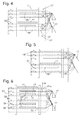
- Fig. 1 is a schematic side view of a printing machine according to the invention.
- Two reel changers 01 are connected to a printing tower 02 with five printing units 03 for printing on both sides of a web 04 passed through; 06 arranged.
- the unwound from the roll changers 01 tracks 04; 06 are feasible on different ways through the printing tower 02. Shown is a configuration in which the web 04 passes through the lower four printing units 03 and is printed in four colors, and the web 06 is printed black and white in the uppermost printing unit 03.
- configurations can also be set in which one of the tracks 04; 06 two and the other passes through three printing units, etc.
- the printed in printing tower 02 tracks 04; 06 are each supplied to one of two turning and mixing stages 07, which are arranged one above the other and, as the plan view of FIG. 2, in a rectilinear series with the roll changers 01 and the printing tower 02.
- printing tower 02 'and roll changer 01' may be arranged for its supply.
- a longitudinal cutting device 08 e.g. in the form of two draw rollers rotating in contact with each other, between each of which a web 04; 06 is performed, and one of which carries a rotating blade.
- the longitudinal cutting device 08 is required by the tracks 04; 06 off so that they pass through uncut.
- Each turning and mixing stage 07 essentially comprises three at an angle of 45 ° to the transport direction of the web 04; 06 arranged deflecting rods 09; 11.
- the Length of the middle deflection bar 11 is dimensioned so that it is capable of a web 04; 06 with the maximum width processable by printing tower 02 can be deflected by 90 °; the two outer deflection rods 09 have a smaller, each for deflecting a partial web 13 generated at the longitudinal cutting device 08; 14; 21; 22 designed width.
- the deflecting rods 09 and 11 are independently displaceable in horizontal rails 12, which are aligned along the reel splitter 01, printing tower 02 and turning and mixing stage 07 connecting line.
- the web 04 or 06 leaves the turning and mixing stage 07 deflected by 90 °.
- the two short deflection rods 09 are each placed so that generated at the longitudinal cutting device 08 partial webs 13; 14; 21; 22 come to lie exactly above each other at the output of the turning and mixing stage 07. This is independent of the width of the supplied web 04; 06 possible because the deflection rods 09 are mutually displaceable. Also by moving the deflecting rods 09 and 11, it is possible, the exiting from the turning and mixing stage 07 web 04; 06 or partial webs 13; 14; 21; 22 align exactly on a former 17 of a folder 16 and to fold them so centrally along.
- the turning bars 09; 11 are about a vertical axis by 90 ° or about a horizontal to the web transport direction parallel axis by 180 ° pivotally about a looped around track 04; 06 or partial web 13; 14; 21; 22 first to lead to a turning bar 18 where it is turned by 180 ° and finally fed to the former 17.
- a longitudinal axis of the inlet of the former 17 is arranged at 90 ° to the longitudinal axis of a cylinder of the printing unit 03.
- the turning bars 18 also serve partial webs 13; 14; 21; 22 to exchange between different turning and mixing stages 07, as is clear from FIGS. 3 to 6.
- 3 shows a schematic view of two superposed turning and mixing stages 07, each with two short deflection rods 09 and one long deflection rod 11, which are held in frame elements 19.
- Two triangles symbolize two superposed formers 17 of the folding apparatus 16.
- These opposite a plurality of groups of turning bars 18 are arranged; each deflecting bar 09; 11 three turning bars 18 are assigned. Dashed lines symbolize possible web guides.
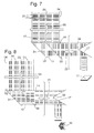
- FIG. 4 shows a simple example in which in the upper turning and mixing stage 07 two partial webs 13 produced from the web 06; 14 and in the lower turning and mixing stage 07 from the web 04 generated partial webs 21; 22 deflected and directly, while maintaining their order, the upper former 17 are fed. Of course, one or more lower partial webs 21; 22 or all partial webs 13; 14; 21; 22 are guided on the lower former 17.
- the partial web 21 is guided over the turning bars 18 in the upper turning and mixing stage 07 and is fed from there from the former 17 as the uppermost web 21.
- a printed product is obtained whose outermost and innermost sheets each have a different color than the two intermediate sheets.
- every other partial path 13; 14; 21; 22 are exchanged between the turning and mixing stages 07, or it could also be several partial webs 13; 14; 21; 22 be replaced at the same time.
- a arranged on the turning bars 18 longitudinal cutting device 23 allows a partial web 13; 14; 21; 22, in the case of FIG. 6, the partial web 21, in the middle in two half-width partial webs 21 a; 21 b to disassemble, each resulting in the configuration shown here, a single inner leaf in the two formers 17 fed strands.
- the longitudinal cutting device 23 of FIG. 6 is arranged at a position where they each act on an exchanged between the turning and mixing stages 07 partial web 21 can. It would also be conceivable, each sub-train 13; 14; 21; 22 to assign a longitudinal cutting device 23, for the partial web 21, for example, at the designated 24 location.
- Fig. 7 illustrates a newspaper production in broadsheet format.
- the plate cylinders of the double wide printing units 03 carry four plates side by side and print four pages 28 with horizontal lines next to each other.
- the printed web 04 is at the longitudinal cutting device 08 in the two partial webs 13; 14 disassembled.
- the longitudinal cutting device 08 need not be displaceable transversely to the web 04, because even if webs 04 of different widths are used, they are always guided centered by the printing unit 03, so that the boundary line 29 between the second and third sides always exactly on the blade Slitter 08 meets.
- the diverted to the Umlenkstangen 09 partial webs 13; 14 are aligned exactly so that the boundary line 31 between the two sides of the partial webs 13; 14 exactly meets the nose 32 of the former 17, so that a longitudinal fold in this boundary line 31 is generated.
- One by separating the folded part webs 13; 14 obtained signature 33 includes eight pages on two nested sheets. Different page numbers are of course by adding additional partial webs 21; 22 reachable on the former 17. Since it is always possible by moving the Umlenkstangen 09, the boundary lines 31 of the partial webs 13; 14 to align the folding nose 32, regardless of the width of the partial webs 13; 14, no lateral adjustability is required for the former 17. Tracks 04; 06 different widths are therefore very easy to use.
- FIG. 8 shows the processing of a web 04 printed in tabloid format.
- four double pages 34 are printed side by side with vertical orientation of the lines.
- the web 04 is cut at the boundary line 29 by the slitter 08, and the resulting part webs 13; 14 are superimposed with the help of the Umlenkstangen 09.
- Another longitudinal cutting device 23 separates the partial webs 13; 14 along the boundary line 31, so that in the former 17, the resulting four partial webs are simply superimposed. Separate and Querfalzen results in the finished signature 36, which has sixteen pages on four sheets here, but the page number could also be doubled by collecting operation at the cross folds or enlarged by adding further partial webs.
- Fig. 9 illustrates the operation of the machine according to the invention in commercial printing.
- the web 37 used for this purpose is narrower than the web 04 used for newspaper printing, as viewed in FIGS. 7 and 8, the edges of which are shown in FIG. 9 as dotted lines.
- the longitudinal cutting device 08 is turned off the web 37, and the web 37 is undivided deflected at the long deflecting rod 11 to the former 17 and folded in this.
- a former 17 is used, which is wider than half the width of the Printing unit 03, ie the effective pressure surface of the cylinder, is. Double-wide means that the printing unit 03 has at least a width of four newspaper pages.
- a more than single wide web 04; 06, ie a web 04; 06 with a width of more than two newspaper pages, but smaller than a double-width web 04; 06 is located centrally in the printing unit 03.
- the printing unit 03 prints while the web 04; 06 with two newspaper pages.
- a slitter 08 is arranged to form a double-width web 04; 06, ie, a four-page pages having web 04; 06, halved and the two resulting webs 13; 14; 21; 22 are arranged on the former 17.
Landscapes
- Engineering & Computer Science (AREA)
- Mechanical Engineering (AREA)
- Folding Of Thin Sheet-Like Materials, Special Discharging Devices, And Others (AREA)
- Ink Jet (AREA)
- Printers Characterized By Their Purpose (AREA)
- Printers Or Recording Devices Using Electromagnetic And Radiation Means (AREA)
- Materials For Photolithography (AREA)
- Dot-Matrix Printers And Others (AREA)
- Auxiliary Devices For And Details Of Packaging Control (AREA)
- Labeling Devices (AREA)
Abstract
Description
Die Erfindung betrifft eine Druckmaschine mit mindestens einem Druckwerk gemäß dem Oberbegriff des Anspruches 1.The invention relates to a printing machine with at least one printing unit according to the preamble of claim 1.
Es sind einfach breite und doppelt breite Druckwerke bekannt, d.h. Druckwerke, deren Breite so bemessen ist, dass sie zwei bzw. vier Druckplatten nebeneinander zu tragen im Stande sind. Wenn eine Druckmaschine mit einfach breiter Druckstufe zum Drucken eines Broadsheet-Erzeugnisses eingesetzt wird, so wird der bedruckte Strang im Falztrichter des Falzapparats längs gefalzt und anschließend in Signaturen zerschnitten. Es können auch Tabloid-Erzeugnisse gedruckt werden, wenn zwischen Druckstufe und Falzapparat eine Längsschneideinrichtung vorhanden ist, die die bedruckte Bahn mittig längs schlitzt. In diesem Fall werden die zwei Teilbahnen im Falztrichter übereinander gelegt, in Stücke zerschnitten und eine Signatur entsteht erst durch nachfolgendes Querfalzen der abgeschnittenen Stücke. Die Umstellung zwischen Tabloid- und Broadsheet-Produktion ist vergleichsweise einfach, auch wenn für beide Produktionen Bahnen unterschiedlicher Breite verwendet werden. Wenn die Bahnen bezüglich einer Mittellinie zentriert durch die Druckmaschine geführt werden, sind die Längsschneideinrichtung und die Nase des Falztrichters stets korrekt positioniert.There are simply wide and double wide printing units known, i. Printing units whose width is such that they are capable of carrying two or four printing plates next to one another. When a single width printing press is used to print a broadsheet product, the printed strand is longitudinally folded in the folder's former hopper and then cut into signatures. It is also possible to print tabloid products if there is a longitudinal cutting device between the printing stage and the folder which slits the printed web centrally. In this case, the two partial webs are superimposed in the former, cut into pieces and a signature is formed only by subsequent transverse folding of the cut pieces. Switching between tabloid and broadsheet production is comparatively easy, even though webs of different widths are used for both productions. When the webs are centered through the press with respect to a center line, the slitter and nose of the former are always properly positioned.
Doppelt breite Druckstufen sind in der Lage, über die Breite einer Bahn verteilt vier Druckseiten nebeneinander zu drucken. Eine solche doppelt breite Bahn muss, bevor sie eine Wende- und Mischstufe durchläuft, wenigstens einmal mittig längs geschnitten werden, um zwei Teilbahnen mit je zwei Seiten Breite zu erzeugen. Nach Mischen und gegebenenfalls Wenden werden diese wiederum Falztrichtern eines Falzapparates zugeführt. Wenn eine solche Maschine in der Lage sein soll, Bahnen mit wechselnden Breiten zu verarbeiten, so muss entweder die Position der Falztrichter an die Breite der Bahn anpassbar sein, oder, falls sie fest ist, muss die Wende- und Mischstufe in der Lage sein, die zwei Teilbahnen um einen Bruchteil ihrer Breite seitlich so zu versetzen, dass sie korrekt zentriert auf die Falztrichter treffen und die Längsfalz an der richtigen Stelle erzeugt wird. Wenn Broadsheet-Produkte mit Einlegeblatt oder Tabloid-Produkte erzeugt werden, müssen die von der ersten Längsschneideinrichtung erzeugten Teilbahnen mit Hilfe von zwei Längsschneideinrichtungen abermals durchteilt werden. Dies ist bei wechselnden Bahnbreiten auch nur dann korrekt möglich, wenn wenigstens die zweiten Längsschneideinrichtungen quer zur Bahn verschiebbar sind.Double-width printing stages are capable of printing four printed pages side by side across the width of a web. Such a double-width web must, before it passes through a turning and mixing stage, be cut longitudinally at least once in the middle to produce two partial webs each having two sides of width. After mixing and optionally turning these are in turn fed to the formers of a folder. If such a machine is to be able to process webs of varying widths, then either the position of the former must be equal to the width of the web Be adaptable web, or if it is fixed, the turning and mixing stage must be able to laterally offset the two partial webs by a fraction of their width so that they hit correctly centered on the former and the longitudinal fold in the right place is produced. When broadsheet products are produced with insert sheet or tabloid products, the part webs produced by the first slitter must be divided again by means of two slitters. This is only possible correctly with changing web widths if at least the second longitudinal cutting devices are displaceable transversely to the web.
Diese Probleme lassen es auf den ersten Blick sinnvoll erscheinen, für Druckaufgaben, die die Verwendung von Bahnen mit wechselnden Breiten erfordern, einfach breite Druckmaschinen einzusetzen. Dies hat jedoch den Nachteil, dass die Zahl an einfach breiten Druckwerken, die zur Herstellung einer Signatur mit gegebenem Seitenumfang benötigt wird, doppelt so groß ist wie die Zahl von zum gleichen Zweck benötigten doppelt breiten Druckwerken, und dass zwei einfach breite Druckwerken in der Herstellung und folglich auch in der Anschaffung deutlich teurer sind, als ein doppelt breites Druckwerk. Hinzu kommt, dass die auf dem Markt verfügbaren doppelt breiten Druckwerke häufig für höhere Bahngeschwindigkeiten ausgelegt sind als einfach breite Druckwerke, so dass man, um eine einfach breite Druckmaschine hoher Leistung zu bauen, nicht auf existierende Komponenten zurückgreifen kann, sondern die Druckwerke neu konstruieren muss.These problems make it seem reasonable to use wide presses for print jobs that require the use of webs of varying widths. However, this has the disadvantage that the number of single-width printing units required to produce a signature with a given page size is twice as large as the number of double-width printing units required for the same purpose, and that two simple-width printing units are being manufactured and consequently also much more expensive to buy than a double-width printing unit. In addition, the double-wide printing presses available on the market are often designed for higher web speeds than simply wide-format presses, so that to build a high-performance, single-width press can not rely on existing components, but redesign the print works ,
Die DE 197 28 207 A1 offenbart eine Druckmaschine mit zwei zwischen Drucktürmen angeordneten Wendetürmen, die die quer zu den Zylinderachsen der Druckwerke laufenden Bahnen längs zu den Zylinderachsen umlenken und auf einen Falzapparat führen, wobei die Falztrichter quer zu den Zylinderachsen angeordnet sind.DE 197 28 207 A1 discloses a printing machine with two arranged between printing towers turning towers, which deflect the transverse to the cylinder axes of the printing units running tracks along the cylinder axes and lead to a folder, wherein the formers are arranged transversely to the cylinder axes.
Die DE 44 19 217 A1 zeigt eine Druckmaschine mit einem Längsfalztrichter, dessen Breite ungefähr die Breite der Druckwerke aufweist.DE 44 19 217 A1 shows a printing machine with a Längsfalztrichter whose width has approximately the width of the printing units.
Durch den Artikel im Polygraph 1965, Seiten 508 bis 512 "Falzvorrichtungen an Rollen-Tiefdruckmaschinen" von Engelbert Muth ist es beispielsweise bekannt, Papierbahnen durch Verschieben von Wendestangen seitlich zu justieren.By the article in the Polygraph 1965, pages 508 to 512 "folding devices on roll gravure printing machines" by Engelbert Muth, it is known, for example, to adjust paper webs by moving turner bars laterally.
Der Artikel "Der Falzaufbau (Überbau)" von Wolfgang Walenski, "Der Rollenoffsetdruck", 1. Aufl. Fellbach: Fachschriften- Verl. 1995, Seiten 186-197 offenbart verschiedene Bahnführungen mittels Wendestangen zu Trichtern. Beispielsweise ist auf Seite 194 dargestellt, eine Bahn in zwei Teilbahnen zu zerschneiden, diese Teilbahnen übereinander zu legen und mittig einem Trichter zuzuführen.The article "The folding structure (superstructure)" by Wolfgang Walenski, "The web offset printing", 1 st edition Fellbach: Fachschriften- Verl. 1995, pages 186-197 discloses various web guides by turning bars to funnels. For example, it is shown on page 194 to cut a web into two partial webs, to superimpose these partial webs and to supply them centrally to a funnel.
Die US 37 34 487 A zeigt verschiebbare Wendestangen.The US 37 34 487 A shows sliding turner bars.
Die DE 101 31 976 A1 offenbart Druckmaschinen für variable Bahnbreiten mit geradem Bahnverlauf und mehreren Trichtern nebeneinander.DE 101 31 976 A1 discloses printing machines for variable web widths with a straight path and several hoppers next to each other.
Der Erfindung liegt die Aufgabe zugrunde, eine Druckmaschine mit mindestens einem Druckwerk zu schaffen.The invention has for its object to provide a printing machine with at least one printing unit.
Die Aufgabe wird erfindungsgemäß durch die Merkmale des Anspruches 1 gelöst.The object is achieved by the features of claim 1.
Zu den Vorteilen der Druckmaschine gehört ein einfacher, kompakter Aufbau, der es erlaubt, eine bedruckte Bahn in zwei Teilbahnen zu zerlegen und diese Teilbahnen auf einfache Weise unabhängig von ihrer Breite exakt übereinander zu legen.Among the advantages of the printing press is a simple, compact design that allows to dissect a printed web into two sub-webs and to place these sub-webs in a simple manner, regardless of their width exactly on top of each other.
Dies wird im Wesentlichen dadurch erreicht, dass die Wende- und Mischstufe der Druckmaschine den in die Horizontale projizierten Weg der Bahn vom Druckwerk zum Falzapparat mit Hilfe von zwei Umlenkstangen seitwärts abknickt, die von jeweils einer Teilbahn umschlingbar sind, welche eine Längsschneideinrichtung aus einer der Wendeund Mischstufe zugeführten bedruckten Bahn erzeugt, und dass diese zwei Umlenkstangen horizontal verschiebbar sind.This is achieved essentially by the fact that the turning and mixing stage of the printing press projects the projected horizontally projected path of the web from the printing unit to the folder sideways by means of two deflection bars, which are wrapped by a respective part of a web, which a slitter from one of the Wendeund Mixing fed fed printed web, and that these two deflection rods are horizontally displaceable.
Diese zwei Umlenkstangen können im Prinzip in einer beliebigen nicht zu ihrer Achse parallelen Richtung verschiebbar sein, um die Position, an der die Teilbahnen aus der Wende- und Mischstufe austreten, festzulegen. Bevorzugt ist allerdings eine Verschiebbarkeit parallel zum Weg der Bahn zwischen Druckwerk und Wende- und Mischstufe. Bei einer solchen Anordnung ändert sich der von der Teilbahn umschlungene Bereich einer Umlenkstange nicht, wenn diese verschoben wird, so dass der Verschiebbarkeitsbereich der von der Wende- und Mischstufe zum Falzapparat verlaufenden Bahnen lediglich durch die Bewegungsfreiheit der Umlenkstangen begrenzt ist.In principle, these two deflection rods can be displaceable in any direction which is not parallel to their axis in order to determine the position at which the component webs emerge from the turning and mixing stage. However, a displacement is preferably parallel to the path of the web between printing unit and turning and mixing stage. In such an arrangement, the region of a deflection bar which is looped around by the partial web does not change when it is displaced, so that the displaceability range of the webs extending from the turning and mixing stage to the folder is limited only by the freedom of movement of the deflection rods.
Wenn man davon ausgeht, dass jede in der Druckmaschine verarbeitete Bahn längs geschnitten wird und die resultierenden Teilbahnen vor dem Eintritt in den Falzapparat übereinander gelegt werden, oder wenn man annimmt, dass Bahnen, die eine festgelegte Grenzbreite überschreiten, stets geschnitten werden, während Bahnen mit darunterliegender Breite auch ungeschnitten bleiben können, können Platz und Kosten gespart werden, wenn der Falzapparat schmaler als die Druckstufe gebaut ist, genauer gesagt, wenn ein Eingang des Falzapparats ― der keine Bahnen mit der vollen von dem Druckwerk verarbeitbaren Breite bewältigen können muss - schmaler ist als ein Ausgang des Druckwerkes.Assuming that each web processed in the printing press is cut longitudinally and the resulting part webs are overlapped before entering the folder, or assuming that webs exceeding a predetermined limit width are always cut while webs with Underlying width can also remain uncut, space and cost can be saved if the folder is built narrower than the printing stage, more precisely, if an input of the folder - which must be able to handle any webs with the full processable width of the printing unit - is narrower as an output of the printing unit.
Vorzugsweise ist das Druckwerk doppelt breit, und der Falzapparat ist nur zur Verarbeitung von einfach breiten Bahnen ausgelegt.Preferably, the printing unit is twice as wide, and the folder is designed only for processing single-width webs.
Die Wende- und Mischstufe weist zum Umlenken einer Bahn bzw. der aus ihr geschnittenen Teilbahnen zwei oder drei Umlenkstangen auf. Da es nicht nötig ist, eine der Umlenkstangen über die andere hinweg verschieben zu können, können alle Umlenkstangen in einer gemeinsamen Führungsschiene geführt sein. Dabei hat wenigstens eine Umlenkstange die zum Umlenken einer Bahn maximaler Breite erforderliche Länge; jede weitere Umlenkstange kann kürzer sein.The turning and mixing stage has two or three deflection rods for deflecting a web or its part webs cut from it. Since it is not necessary to be able to move one of the deflection rods over the other, all can Be guided deflection rods in a common guide rail. In this case, at least one deflecting rod has the length required for deflecting a web of maximum width; each additional deflection bar can be shorter.
Da durch die Verschiebbarkeit der Umlenkstangen jede dem Falzapparat zugeführte Bahn eine beträchtliche Bewegungsfreiheit in Querrichtung hat, ist eine Beweglichkeit des Falztrichters nicht erforderlich, um eine korrekte Ausrichtung der Bahn oder der Teilbahnen auf den Falztrichter zu erreichen.Because of the displaceability of the deflecting bars, each web fed to the folder has considerable freedom of movement in the transverse direction, mobility of the former is not required in order to achieve correct alignment of the web or the part webs on the former.
Eine zweite Längsschneideinrichtung zum Längsschneiden einer Teilbahn ist vorzugsweise so an der Wende- und Mischstufe auf dem Transportweg der Bahn hinter einer Umlenkstange angeordnet, dass sie auf eine an der Umlenkstange umgelenkte Teilbahn wirkt. Sie ist zweckmäßigerweise auf den Falztrichter zentriert, so dass ihre Schneidlinie mit der Nase des Falzzylinders zusammenfällt. Da die der zweiten Längsschneideinrichtung zugeführte Bahn mit Hilfe der Umlenkstange quer verschiebbar ist und ihr deshalb unabhängig von ihrer Breite stets exakt zentriert zugeführt werden kann, ist eine Verschiebbarkeit auch dieser Längsschneideinrichtung nicht erforderlich.A second longitudinal cutting device for longitudinal cutting of a partial web is preferably arranged at the turning and mixing stage on the transport path of the web behind a deflection bar, that it acts on a deflected part of the deflection bar. It is expediently centered on the former, so that its cutting line coincides with the nose of the folding cylinder. Since the web fed to the second longitudinal cutting device is transversely displaceable with the aid of the deflecting rod and therefore can always be fed exactly centered regardless of its width, a displaceability of this longitudinal cutting device is also unnecessary.
An einer vom Falzapparat abgewandten Seite der Wende- und Mischstufe ist vorzugsweise eine Wendestange angebracht. Während bei einer Bahn, die lediglich um eine Umlenkstange herumgeführt ist, Ober- und Unterseite beim Durchgang durch die Wende- und Mischstufe vertauscht werden, ist es durch Herumschlingen der Bahn auch um die Wendestange möglich, die Bahn ohne Vertauschung von Ober- und Unterseite durch die Wende- und Mischstufe zu führen.At a side facing away from the folder side of the turning and mixing stage preferably a turning bar is attached. Whereas in the case of a web which is merely guided around a deflection bar, the top and bottom are interchanged when passing through the turning and mixing stage, it is also possible to loop around the turning bar around the web, and the web can pass through the top and bottom without interchanging to lead the turning and mixing stage.
Wenn zur Verarbeitung mehrerer Bahnen gleichzeitig mehrere Wende- und Mischstufen übereinander angeordnet sind, kann eine solche Wendestange auch genutzt werden, um Bahnen zwischen den Wende- und Mischstufen auszutauschen.If several turning and mixing stages are arranged at the same time for processing a plurality of webs, such a turning bar can also be used to exchange webs between the turning and mixing stages.
Die zweite Längsschneideinrichtung kann am Weg einer Bahn von einer Wende- und Mischstufe zur anderen angeordnet sein. Die von dieser Längsschneideinrichtung erzeugten zwei Teilbahnen können jeweils unterschiedlichen Wende- und Mischstufen zugeführt werden. Es ist auch möglich, die zweite Längsschneideinrichtung unmittelbar am Ausgang der Wende- und Mischstufe zu platzieren, dies ist insbesondere für das Drucken von Tabloid-Erzeugnissen zweckmäßig.The second longitudinal cutting device can be arranged on the path of a web from one turning and mixing stage to the other. The two partial webs generated by this longitudinal cutting device can each be supplied to different turning and mixing stages. It is also possible to place the second longitudinal cutting device directly at the exit of the turning and mixing stage, this is particularly useful for the printing of tabloid products.
Wenn die Druckmaschine mehr als zwei Druckwerke umfasst, so ist die Wende- und Umlenkstufe vorzugsweise zwischen beiden angeordnet, so dass ihr Bahnen wahlweise von beiden Seiten zugeführt werden können.If the printing press comprises more than two printing units, then the turning and deflecting stage is preferably arranged between the two, so that their webs can be selectively fed from both sides.
Ausführungsbeispiele der Erfindung sind in den Zeichnungen dargestellt und werden im folgenden näher beschrieben.Embodiments of the invention are illustrated in the drawings and will be described in more detail below.
Es zeigen:
- Fig. 1
- eine schematische Seitenansicht einer erfindungsgemäßen Druckmaschine;
- Fig. 2
- eine Draufsicht auf die Druckmaschine aus Fig. 1;
- Fig. 3
- eine schematische Darstellung von zwei Wende- und Mischstufen der Druckmaschine;
- Fig. 4 bis 6
- Beispiele von Bahnführungen in den Wende- und Mischstufen; und
- Fig. 7 bis 9
- verschiedene Arten, eine Papierbahn in der erfindungsgemäßen Maschine zu schneiden und zu falzen.
- Fig. 1
- a schematic side view of a printing machine according to the invention;
- Fig. 2
- a plan view of the printing machine of FIG. 1;
- Fig. 3
- a schematic representation of two turning and mixing stages of the printing machine;
- 4 to 6
- Examples of web guides in the turning and mixing stages; and
- Fig. 7 to 9
- various ways to cut and fold a paper web in the machine according to the invention.
Fig. 1 ist eine schematische Seitenansicht einer Druckmaschine gemäß der Erfindung. Zwei Rollenwechsler 01 sind an einen Druckturm 02 mit fünf Druckwerken 03 zum jeweils beidseitigen Bedrucken einer hindurchgeführten Bahn 04; 06 angeordnet. Die von den Rollenwechslern 01 abgewickelten Bahnen 04; 06 sind auf unterschiedlichen Wegen durch den Druckturm 02 führbar. Gezeigt ist eine Konfiguration, in der die Bahn 04 die unteren vier Druckwerke 03 durchläuft und vierfarbig bedruckt wird, und die Bahn 06 im obersten Druckwerk 03 schwarzweiß bedruckt wird. Selbstverständlich können auch Konfigurationen eingestellt werden, in denen eine der Bahnen 04; 06 zwei und die andere drei Druckwerke durchläuft, etc.Fig. 1 is a schematic side view of a printing machine according to the invention. Two
Die im Druckturm 02 bedruckten Bahnen 04; 06 werden jeweils einer von zwei Wendeund Mischstufen 07 zugeführt, die übereinander und, wie die Draufsicht der Fig. 2 zeigt, in einer geradlinigen Reihe mit den Rollenwechslern 01 und dem Druckturm 02 angeordnet sind.The printed in
In Verlängerung dieser Reihe können ein weiterer, in Fig. 1 und 2 gestrichelt dargestellter Druckturm 02' und Rollenwechsler 01' zu seiner Versorgung angeordnet sein. In diesem Druckturm 02' bedruckte Bahnen 04'; 06' werden ebenfalls Wende- und Mischstufen zugeführt, die mit den Stufen 07 einen Stapel bilden.In extension of this series, another, in dashed lines in Fig. 1 and 2 illustrated printing tower 02 'and roll changer 01' may be arranged for its supply. In this printing tower 02 'printed webs 04'; 06 'are also supplied turning and mixing stages, which form a stack with the
Zwischen dem Druckturm 02 und der Wende- und Mischstufe 07 befindet sich eine Längsschneideinrichtung 08, z.B. in Form von zwei in Kontakt miteinander rotierenden Zugwalzen, zwischen denen jeweils eine Bahn 04; 06 durchgeführt ist, und von denen eine eine rotierende Klinge trägt. Die Längsschneideinrichtung 08 ist bei Bedarf von den Bahnen 04; 06 abstellbar, so dass sie diese ungeschnitten durchlässt.Between the
Jede Wende- und Mischstufe 07 umfasst im Wesentlichen drei unter einem Winkel von 45° zur Transportrichtung der Bahn 04; 06 angeordnete Umlenkstangen 09; 11. Die Länge der mittleren Umlenkstange 11 ist so bemessen, dass diese in der Lage ist, eine Bahn 04; 06 mit der maximalen von Druckturm 02 verarbeitbaren Breite um 90° umzulenken; die zwei äußeren Umlenkstangen 09 haben eine geringere, jeweils zum Umlenken einer an der Längsschneideinrichtung 08 erzeugten Teilbahn 13; 14; 21; 22 ausgelegte Breite. Die Umlenkstangen 09 und 11 sind unabhängig von einander in horizontalen Schienen 12 verschiebbar, die entlang der Rollenwechsler 01, Druckturm 02 und Wende- und Mischstufe 07 verbindenden Linie ausgerichtet sind. Die Bahn 04 oder 06 verlässt die Wende- und Mischstufe 07 um 90° abgelenkt. Dabei sind die zwei kurzen Umlenkstangen 09 jeweils so plaziert, dass an der Längsschneideinrichtung 08 erzeugte Teilbahnen 13; 14; 21; 22 am Ausgang der Wende- und Mischstufe 07 exakt übereinander zu liegen kommen. Dies ist unabhängig von der Breite der zugeführten Bahn 04; 06 möglich, da die Umlenkstangen 09 gegeneinander verschiebbar sind. Ebenfalls durch Verschieben der Umlenkstangen 09 bzw. 11 ist es möglich, die aus der Wende- und Mischstufe 07 austretende Bahn 04; 06 oder Teilbahnen 13; 14; 21; 22 exakt auf einen Falztrichter 17 eines Falzapparats 16 auszurichten und sie so mittig längs zu falzen.Each turning and mixing
Die Wendestangen 09; 11 sind um eine vertikale Achse um 90° oder um eine Horizontale zur Bahntransportrichtung parallele Achse um 180° schwenkbar, um eine sie herumgeschlungene Bahn 04; 06 oder Teilbahn 13; 14; 21; 22 zunächst zu einer Wendestange 18 zu führen, wo sie um 180° gewendet und schließlich dem Falztrichter 17 zugeführt wird. Eine Längsachse des Einlaufes des Falztrichters 17 ist 90° zur Längsachse eines Zylinders des Druckwerkes 03 angeordnet.The turning bars 09; 11 are about a vertical axis by 90 ° or about a horizontal to the web transport direction parallel axis by 180 ° pivotally about a looped around
Die Wendestangen 18 dienen auch dazu, Teilbahnen 13; 14; 21; 22 zwischen verschiedenen Wende- und Mischstufen 07 auszutauschen, wie anhand der Fig. 3 bis 6 deutlich wird. Fig. 3 zeigt eine schematische Ansicht von zwei übereinander liegenden Wende- und Mischstufen 07 mit jeweils zwei kurzen Umlenkstangen 09 und einer langen Umlenkstange 11, die in Gestellelementen 19 gehalten sind. Zwei Dreiecke symbolisieren zwei übereinander liegende Falztrichter 17 des Falzapparats 16. Diesen gegenüberliegend sind mehrere Gruppen von Wendestangen 18 angeordnet; jeder Umlenkstange 09; 11 sind drei Wendestangen 18 zugeordnet. Gestrichelte Linien symbolisieren mögliche Bahnführungen.The turning bars 18 also serve
Konkrete Beispiele für Bahnführungen sind in den Fig. 4 bis 6 gezeigt. Fig. 4 zeigt ein einfaches Beispiel, bei dem in der oberen Wende- und Mischstufe 07 zwei aus der Bahn 06 erzeugte Teilbahnen 13; 14 und in der unteren Wende- und Mischstufe 07 aus der Bahn 04 erzeugte Teilbahnen 21; 22 umgelenkt und direkt, unter Beibehaltung ihrer Reihenfolge, dem oberen Falztrichter 17 zugeführt werden. Selbstverständlich könnten auch ein oder mehrere untere Teilbahnen 21; 22 oder alle Teilbahnen 13; 14; 21; 22 auf den unteren Falztrichter 17 geführt werden.Concrete examples of web guides are shown in Figs. 4-6. Fig. 4 shows a simple example in which in the upper turning and mixing
Bei der Konfiguration der Fig. 5 ist die Teilbahn 21 über die Wendestangen 18 in die obere Wende- und Mischstufe 07 geführt und wird von da aus dem Falztrichter 17 als oberste Bahn 21 zugeführt. So wird ein Druckerzeugnis erhalten, dessen äußerstes und innerstes Blatt jeweils eine andere Farbigkeit aufweisen als die zwei dazwischen liegenden Blätter. Selbstverständlich wäre es auch möglich, die Teilbahn 21 zwischen den Teilbahnen 13 und 14 dem Falztrichter 17 zuzuführen. Genauso könnte jede andere Teilbahn 13; 14; 21; 22 zwischen den Wende- und Mischstufen 07 ausgetauscht werden, oder es könnten auch mehrere Teilbahnen 13; 14; 21; 22 gleichzeitig ausgetauscht werden.In the configuration of FIG. 5, the
Eine an den Wendestangen 18 angeordnete Längsschneideinrichtung 23 erlaubt es, eine Teilbahn 13; 14; 21; 22, im Falle der Fig. 6 die Teilbahn 21, mittig in zwei halbbreite Teilbahnen 21 a; 21 b zu zerlegen, die bei der hier gezeigten Konfiguration jeweils ein einzelnes Innenblatt in den den zwei Falztrichtern 17 zugeführten Strängen ergeben. Die Längsschneideinrichtung 23 der Fig. 6 ist an einer Stelle angeordnet, wo sie jeweils auf eine zwischen den Wende- und Mischstufen 07 ausgetauschte Teilbahn 21 einwirken kann. Denkbar wäre auch, jeder Teilbahn 13; 14; 21; 22 eine Längsschneideinrichtung 23 zuzuordnen, für die Teilbahn 21 z.B. an der mit 24 bezeichneten Stelle. Dadurch würde die Möglichkeit geschaffen, von den zwei Teilbahnen 21 a; 21 b eine z.B. auf dem mit 26 bezeichneten Weg den Falztrichtern 17 zuzuführen. Denkbar wäre auch die Anbringung einer Längsschneideinrichtung 23 jeweils auf dem direkten Weg zwischen einer Wendestange 09 und den Falztrichtern 17, für die Teilbahn 21 etwa an dem in Fig. 4 mit 27 bezeichneten Ort, um die daraus resultierenden Teilbahnen jeweils einem oder verschiedenen Falztrichtern 17 zuzuführen.A arranged on the turning bars 18
Je nach Breite der verwendeten Bahnen 04; 06 ergibt sich eine große Vielfalt von Produktionsmöglichkeiten. Fig. 7 veranschaulicht eine Zeitungsproduktion im Broadsheet-Format. Die Plattenzylinder der doppelt breiten Druckwerke 03 tragen vier Platten nebeneinander und drucken jeweils vier Seiten 28 mit horizontalen Zeilen nebeneinander.Depending on the width of the
Die bedruckte Bahn 04 wird an der Längsschneideinrichtung 08 in die zwei Teilbahnen 13; 14 zerlegt. Die Längsschneideinrichtung 08 braucht nicht quer zur Bahn 04 verschiebbar zu sein, denn auch wenn Bahnen 04 unterschiedlicher Breite eingesetzt werden, werden sie stets zentriert durch das Druckwerk 03 geführt, so dass die Begrenzungslinie 29 zwischen den zweiten und dritten Seiten stets exakt auf die Klinge der Längsschneideinrichtung 08 trifft. Durch Verschieben der Umlenkstangen 09 in Zuführrichtung der Bahn 04, d.h. in vertikaler Richtung in der Figur, können die an den Umlenkstangen 09 umgelenkten Teilbahnen 13; 14 exakt so ausgerichtet werden, dass die Begrenzungslinie 31 zwischen den zwei Seiten der Teilbahnen 13; 14 exakt auf die Nase 32 des Falztrichters 17 trifft, so dass ein Längsfalz in dieser Begrenzungslinie 31 erzeugt wird. Eine durch Vereinzeln der gefalzten Teilbahnen 13; 14 erhaltene Signatur 33 umfasst acht Seiten auf zwei ineinanderliegenden Bögen. Abweichende Seitenzahlen sind natürlich durch Hinzumischen von zusätzlichen Teilbahnen 21; 22 am Falztrichter 17 erreichbar. Da es durch Verschieben der Umlenkstangen 09 stets möglich ist, die Begrenzungslinien 31 der Teilbahnen 13; 14 auf die Falznase 32 auszurichten, unabhängig von der Breite der Teilbahnen 13; 14, ist auch für den Falztrichter 17 keine seitliche Verstellbarkeit erforderlich. Bahnen 04; 06 unterschiedlicher Breite sind daher sehr einfach zu verarbeiten.The printed
Fig. 8 zeigt die Verarbeitung einer im Tabloid-Format bedruckten Bahn 04. Hier werden nebeneinander jeweils vier Doppelseiten 34 mit vertikaler Orientierung der Zeilen gedruckt. In gleicher Weise wie mit Bezug auf Fig. 7 beschrieben, wird die Bahn 04 an der Begrenzungslinie 29 durch die Längsschneideinrichtung 08 aufgeschnitten, und die resultierenden Teilbahnen 13; 14 werden mit Hilfe der Umlenkstangen 09 übereinander gelegt. Eine weitere Längsschneideinrichtung 23 trennt die Teilbahnen 13; 14 entlang der Begrenzungslinie 31, so dass im Falztrichter 17 die resultierenden vier Teilbahnen einfach übereinander gelegt werden. Vereinzeln und Querfalzen ergibt die fertige Signatur 36, die hier sechzehn Seiten auf vier Bögen aufweist, deren Seitenzahl aber auch durch Sammelbetrieb beim Querfalzen verdoppelt oder durch Hinzumischen weiterer Teilbahnen vergrößert sein könnte.8 shows the processing of a
Fig. 9 veranschaulicht den Betrieb der erfindungsgemäßen Maschine im Akzidenzdruck. Die hierfür verwendete Bahn 37 ist schmaler als die in Fig. 7 und 8 betrachtete, für den Zeitungsdruck verwendete Bahn 04, deren Kanten in Fig. 9 als punktierte Linien dargestellt sind. Die Längsschneideinrichtung 08 ist von der Bahn 37 abgestellt, und die Bahn 37 wird ungeteilt an der langen Umlenkstange 11 zum Falztrichter 17 umgelenkt und in diesem gefalzt.Fig. 9 illustrates the operation of the machine according to the invention in commercial printing. The
Selbstverständlich wären auch im Akzidenzdruck je nach Breite der Bahn 37 und Seitenformat des fertigen Produkts Verarbeitungsweisen mit Längsschneiden wie in Fig. 7 und 8 gezeigt möglich.Of course, even in commercial printing, depending on the width of the
Bei Druckmaschinen mit mindestens einem doppelt breiten Druckwerk 03 und einem Falztrichter 17, ist ein Falztrichter 17 eingesetzt, der breiter als die halbe Breite des Druckwerkes 03, d. h. der wirksamen Druckfläche der Zylinder, ist. Doppelt breit bedeutet, dass das Druckwerk 03 mindestens eine Breite von vier Zeitungsseiten aufweist.In printing machines with at least one double-
In einer anderen Ausführungsform ist in einer Betriebsweise eine mehr als einfach breite Bahn 04; 06, d. h. eine Bahn 04; 06 mit einer Breite von mehr als zwei Zeitungsseiten, die aber kleiner als eine doppelt breite Bahn 04; 06 ist, mittig im Druckwerk 03 angeordnet. Das Druckwerk 03 bedruckt dabei die Bahn 04; 06 mit zwei Zeitungsseiten. In einer anderen Betriebsweise ist eine Längsschneideinrichtung 08 so angeordnet, dass sie eine doppelt breite Bahn 04; 06, d. h. eine vier Zeitungsseiten aufweisende Bahn 04; 06, halbiert und die beiden entstehenden Bahnen 13; 14; 21; 22 auf dem Falztrichter 17 angeordnet sind.In another embodiment, in one mode of operation, a more than single
- 0101
- Rollenwechslerreelstands
- 0202
- Druckturmprinting tower
- 0303
- Druckwerkprinting unit
- 0404
- Bahntrain
- 0505
- --
- 0606
- Bahntrain
- 0707
- Stufen, Wende- und MischstufeSteps, turning and mixing stages
- 0808
- LängsschneideeinrichtungSlitter
- 0909
- Umlenkstange, kurzTurning bar, short
- 1010
- --
- 1111
- Umlenkstange, langTurning bar, long
- 1212
- Schienenrails
- 1313
- Bahn, TeilbahnTrain, subway
- 1414
- Bahn, TeilbahnTrain, subway
- 1515
- --
- 1616
- Falzapparatfolding
- 1717
- Falztrichterformers
- 1818
- Wendestangeturning bar
- 1919
- Gestellelementframe member
- 2020
- --
- 2121
- Bahn, TeilbahnTrain, subway
- 2222
- Bahn, TeilbahnTrain, subway
- 2323
- LängsschneideeinrichtungSlitter
- 2424
- StelleJob
- 2525
- --
- 2626
- Wegpath
- 2727
- Ortplace
- 2828
- Seitepage
- 2929
- Begrenzungslinieboundary line
- 3030
- --
- 3131
- Begrenzungslinieboundary line
- 3232
- Nasenose
- 3333
- Signatursignature
- 3434
- Doppelseitespread
- 3535
- --
- 3636
- Signatursignature
- 3737
- Bahntrain
- 01'01 '
- Rollenwechslerreelstands
- 02'02 '
- Druckturmprinting tower
- 03'03 '
- Druckwerkprinting unit
- 04'04 '
- Bahntrain
- 06'06 '
- Bahntrain
- 21 a21 a
- Teilbahnpart web
- 21 b21 b
- Teilbahnpart web
Claims (3)
Applications Claiming Priority (2)
| Application Number | Priority Date | Filing Date | Title |
|---|---|---|---|
| DE10304295A DE10304295A1 (en) | 2003-02-04 | 2003-02-04 | Printing machine with at least one printing unit, a folder and at least one turning and mixing stage |
| EP03785589A EP1590283B1 (en) | 2003-02-04 | 2003-12-19 | Printing machine comprising at least one printing group, one folder and at least one turn-and-mix stage |
Related Parent Applications (1)
| Application Number | Title | Priority Date | Filing Date |
|---|---|---|---|
| EP03785589A Division EP1590283B1 (en) | 2003-02-04 | 2003-12-19 | Printing machine comprising at least one printing group, one folder and at least one turn-and-mix stage |
Publications (3)
| Publication Number | Publication Date |
|---|---|
| EP1634833A2 true EP1634833A2 (en) | 2006-03-15 |
| EP1634833A3 EP1634833A3 (en) | 2006-03-22 |
| EP1634833B1 EP1634833B1 (en) | 2006-11-15 |
Family
ID=32730709
Family Applications (3)
| Application Number | Title | Priority Date | Filing Date |
|---|---|---|---|
| EP05101871A Expired - Lifetime EP1634833B1 (en) | 2003-02-04 | 2003-12-19 | Printing machine comprising at least one printing group. |
| EP05101869A Expired - Lifetime EP1634832B1 (en) | 2003-02-04 | 2003-12-19 | Printing machine comprising at least one printing group, one folder with a former and at least one turn-and-mix stage. |
| EP03785589A Expired - Lifetime EP1590283B1 (en) | 2003-02-04 | 2003-12-19 | Printing machine comprising at least one printing group, one folder and at least one turn-and-mix stage |
Family Applications After (2)
| Application Number | Title | Priority Date | Filing Date |
|---|---|---|---|
| EP05101869A Expired - Lifetime EP1634832B1 (en) | 2003-02-04 | 2003-12-19 | Printing machine comprising at least one printing group, one folder with a former and at least one turn-and-mix stage. |
| EP03785589A Expired - Lifetime EP1590283B1 (en) | 2003-02-04 | 2003-12-19 | Printing machine comprising at least one printing group, one folder and at least one turn-and-mix stage |
Country Status (7)
| Country | Link |
|---|---|
| US (1) | US7513195B2 (en) |
| EP (3) | EP1634833B1 (en) |
| AT (3) | ATE328830T1 (en) |
| AU (1) | AU2003294663A1 (en) |
| DE (4) | DE10304295A1 (en) |
| ES (1) | ES2277317T3 (en) |
| WO (1) | WO2004069708A1 (en) |
Families Citing this family (17)
| Publication number | Priority date | Publication date | Assignee | Title |
|---|---|---|---|---|
| DE102004041666A1 (en) * | 2004-08-27 | 2006-03-09 | Maschinenfabrik Wifag | Longitudinal folding device with different widths formers |
| DE102005037730B4 (en) * | 2005-04-19 | 2007-02-15 | Koenig & Bauer Ag | printing presses |
| WO2006111522A1 (en) | 2005-04-19 | 2006-10-26 | Koenig & Bauer Aktiengesellschaft | Printing press assemblies |
| EP1871602B1 (en) | 2005-04-19 | 2013-10-02 | Koenig & Bauer Aktiengesellschaft | Printing machine |
| DE102006020054A1 (en) * | 2006-04-29 | 2007-11-08 | Man Roland Druckmaschinen Ag | Rotary press |
| DE102006025758A1 (en) * | 2006-05-31 | 2007-12-06 | Man Roland Druckmaschinen Ag | Turning bar unit for a web-fed rotary printing machine |
| DE102006058196B4 (en) * | 2006-12-11 | 2011-12-01 | Koenig & Bauer Aktiengesellschaft | Printing press system |
| DE102007016494B4 (en) * | 2007-04-05 | 2015-04-09 | Koenig & Bauer Aktiengesellschaft | Web offset printing machine for producing multi-page newspapers |
| EP2014595B1 (en) | 2007-07-12 | 2013-06-19 | Koenig & Bauer Aktiengesellschaft | Printing press, printing press array and method for operating the printing press or printing press array |
| DE102007032831A1 (en) | 2007-07-12 | 2009-01-22 | Koenig & Bauer Aktiengesellschaft | Printing press two parallel press lines covering six broadsheets and deflected at right angles to two former arrays |
| DE102007058650B3 (en) * | 2007-12-04 | 2009-07-30 | Horst-Walter Hauer | printing system |
| DE102009029572B4 (en) * | 2009-09-18 | 2022-09-08 | Manroland Goss Web Systems Gmbh | Web-fed rotary printing system for multi-width webs with single-width folder |
| DE102009055105A1 (en) * | 2009-12-21 | 2011-06-22 | E.C.H. Will GmbH, 22529 | Promotion of multi-ply webs of the paper or cardboard industry |
| JP2012046305A (en) * | 2010-08-26 | 2012-03-08 | Tokyo Kikai Seisakusho Ltd | Digital printing signature production system, and method of producing digital printing signature |
| DE102012013002A1 (en) * | 2011-11-12 | 2013-05-16 | Manroland Web Systems Gmbh | Roller printing machine e.g. newspaper printing machine with print tower has reversal unit positioned laterally beside second printing unit of printing tower, so that second printing unit and reversal unit are operable by gallery plane |
| MX2017002252A (en) * | 2014-08-22 | 2017-09-01 | Pressline Services Inc | Flexible pressline utilizing modular print zones. |
| CN111516379B (en) * | 2020-05-06 | 2021-08-03 | 青岛桑纳电气有限公司 | Tower-type UV printing system for reel material |
Family Cites Families (14)
| Publication number | Priority date | Publication date | Assignee | Title |
|---|---|---|---|---|
| GB352003A (en) | 1930-01-02 | 1931-07-02 | Robert Rutherford Mccormick | Improvements in printing presses |
| US2506053A (en) * | 1945-02-15 | 1950-05-02 | Hoe & Co R | Web cutting and associating means for printing machines |
| US3255679A (en) * | 1964-11-30 | 1966-06-14 | Eckels Roy | Method of making snap-out manifold |
| US3734487A (en) | 1970-12-31 | 1973-05-22 | Harris Intertype Corp | Automatic ribbon associating apparatus |
| US4279184A (en) * | 1979-10-10 | 1981-07-21 | Universal Corrugated Box Machinery Holding Ag | Apparatus for processing longitudinally-moving webs of material |
| JPS601966A (en) | 1983-06-17 | 1985-01-08 | Nippon Telegr & Teleph Corp <Ntt> | Power feeding start and stop system of subscriber's device |
| JPS6019660A (en) * | 1983-07-14 | 1985-01-31 | Tokyo Kikai Seisakusho:Kk | Folder of double-width rotary press |
| US4671501A (en) | 1986-06-23 | 1987-06-09 | Kabushiki Kaisha Tokyo Kikai Seisakusho | Turning-bar-less folding machine of W-width rotary press |
| DE4204254C2 (en) * | 1992-02-13 | 1995-03-16 | Koenig & Bauer Ag | Device for longitudinal folding of several paper webs of the same width in a web-fed rotary printing press |
| JPH08451B2 (en) * | 1992-07-22 | 1996-01-10 | 株式会社東京機械製作所 | Rotary press and paper feeding unit of the rotary press |
| DE4419217A1 (en) * | 1994-06-01 | 1995-12-07 | Roland Man Druckmasch | Double hopper folder |
| DE19728207A1 (en) * | 1997-07-02 | 1999-01-07 | Wifag Maschf | Turret arrangement |
| ATE272555T1 (en) * | 2000-03-22 | 2004-08-15 | Koenig & Bauer Ag | DEVICE FOR DEFLECTING A MATERIAL WEB |
| DE10131976B4 (en) | 2001-07-02 | 2005-12-29 | Koenig & Bauer Ag | Printing machine with several sections |
-
2003
- 2003-02-04 DE DE10304295A patent/DE10304295A1/en not_active Ceased
- 2003-12-19 EP EP05101871A patent/EP1634833B1/en not_active Expired - Lifetime
- 2003-12-19 WO PCT/DE2003/004192 patent/WO2004069708A1/en not_active Application Discontinuation
- 2003-12-19 US US10/543,256 patent/US7513195B2/en not_active Expired - Fee Related
- 2003-12-19 AT AT03785589T patent/ATE328830T1/en not_active IP Right Cessation
- 2003-12-19 ES ES05101871T patent/ES2277317T3/en not_active Expired - Lifetime
- 2003-12-19 AU AU2003294663A patent/AU2003294663A1/en not_active Abandoned
- 2003-12-19 AT AT05101871T patent/ATE345299T1/en not_active IP Right Cessation
- 2003-12-19 DE DE50305999T patent/DE50305999D1/en not_active Expired - Lifetime
- 2003-12-19 EP EP05101869A patent/EP1634832B1/en not_active Expired - Lifetime
- 2003-12-19 AT AT05101869T patent/ATE348065T1/en not_active IP Right Cessation
- 2003-12-19 EP EP03785589A patent/EP1590283B1/en not_active Expired - Lifetime
- 2003-12-19 DE DE50305719T patent/DE50305719D1/en not_active Expired - Lifetime
- 2003-12-19 DE DE50303758T patent/DE50303758D1/en not_active Expired - Lifetime
Non-Patent Citations (1)
| Title |
|---|
| None |
Also Published As
| Publication number | Publication date |
|---|---|
| WO2004069708A1 (en) | 2004-08-19 |
| US7513195B2 (en) | 2009-04-07 |
| ATE345299T1 (en) | 2006-12-15 |
| ATE328830T1 (en) | 2006-06-15 |
| EP1590283B1 (en) | 2006-06-07 |
| EP1634832A3 (en) | 2006-03-22 |
| DE50303758D1 (en) | 2006-07-20 |
| DE50305999D1 (en) | 2007-01-25 |
| ATE348065T1 (en) | 2007-01-15 |
| AU2003294663A1 (en) | 2004-08-30 |
| EP1634832A2 (en) | 2006-03-15 |
| EP1634832B1 (en) | 2006-12-13 |
| DE50305719D1 (en) | 2006-12-28 |
| EP1590283A1 (en) | 2005-11-02 |
| EP1634833A3 (en) | 2006-03-22 |
| DE10304295A1 (en) | 2004-08-19 |
| EP1634833B1 (en) | 2006-11-15 |
| US20060130682A1 (en) | 2006-06-22 |
| ES2277317T3 (en) | 2007-07-01 |
Similar Documents
| Publication | Publication Date | Title |
|---|---|---|
| EP1634833B1 (en) | Printing machine comprising at least one printing group. | |
| EP1867479B1 (en) | Rotary printing press with a printing unit with a printing unit cylinder and method for making a printing unit | |
| EP0107126A1 (en) | Paper web guide in a rotary printing machine | |
| WO2005105447A1 (en) | Web-fed rotary presses comprising a modifiable folding assembly | |
| EP2293940B2 (en) | Web offset press | |
| EP0888887B1 (en) | Turner bar tower configuration | |
| DE102005037730B4 (en) | printing presses | |
| DE102005036451B4 (en) | Device for producing a product section in a web-processing machine | |
| EP1871602B1 (en) | Printing machine | |
| EP1401661B1 (en) | Printing machine with several sections | |
| DE10163209B4 (en) | Device for the production of folded products | |
| EP2193918B1 (en) | Former assembly | |
| EP1632348B1 (en) | Superstructure of a printing press with longitudinal registering devices | |
| EP1888337A1 (en) | Printing press assemblies | |
| DE102007023818B4 (en) | Method for producing a product section in a web-processing machine | |
| EP1456107B1 (en) | Device for producing folded products | |
| EP1718463B1 (en) | Printing machine comprising a former | |
| DE10311636B4 (en) | turning tower | |
| DE10163211C2 (en) | Device for the production of folded products | |
| EP1837179B1 (en) | Roller rotary printing press and a method for creating a printed product | |
| DE102007016494B4 (en) | Web offset printing machine for producing multi-page newspapers | |
| DE102014113745A1 (en) | Web-fed printing press for the deflection-free production of newspapers | |
| DE102009000354A1 (en) | Roller printing machine has printing device with multiple printing units and folding structure, which has folding hopper |
Legal Events
| Date | Code | Title | Description |
|---|---|---|---|
| PUAI | Public reference made under article 153(3) epc to a published international application that has entered the european phase |
Free format text: ORIGINAL CODE: 0009012 |
|
| PUAL | Search report despatched |
Free format text: ORIGINAL CODE: 0009013 |
|
| AC | Divisional application: reference to earlier application |
Ref document number: 1590283 Country of ref document: EP Kind code of ref document: P |
|
| AK | Designated contracting states |
Kind code of ref document: A2 Designated state(s): AT BE BG CH CY CZ DE DK EE ES FI FR GB GR HU IE IT LI LU MC NL PT RO SE SI SK TR |
|
| AX | Request for extension of the european patent |
Extension state: AL LV MK |
|
| AK | Designated contracting states |
Kind code of ref document: A3 Designated state(s): AT BE BG CH CY CZ DE DK EE ES FI FR GB GR HU IE IT LI LU MC NL PT RO SE SI SK TR |
|
| AX | Request for extension of the european patent |
Extension state: AL LV MK |
|
| 17P | Request for examination filed |
Effective date: 20060209 |
|
| GRAP | Despatch of communication of intention to grant a patent |
Free format text: ORIGINAL CODE: EPIDOSNIGR1 |
|
| GRAS | Grant fee paid |
Free format text: ORIGINAL CODE: EPIDOSNIGR3 |
|
| GRAA | (expected) grant |
Free format text: ORIGINAL CODE: 0009210 |
|
| AC | Divisional application: reference to earlier application |
Ref document number: 1590283 Country of ref document: EP Kind code of ref document: P |
|
| AK | Designated contracting states |
Kind code of ref document: B1 Designated state(s): AT BE BG CH CY CZ DE DK EE ES FI FR GB GR HU IE IT LI LU MC NL PT RO SE SI SK TR |
|
| PG25 | Lapsed in a contracting state [announced via postgrant information from national office to epo] |
Ref country code: IE Free format text: LAPSE BECAUSE OF FAILURE TO SUBMIT A TRANSLATION OF THE DESCRIPTION OR TO PAY THE FEE WITHIN THE PRESCRIBED TIME-LIMIT Effective date: 20061115 Ref country code: IT Free format text: LAPSE BECAUSE OF FAILURE TO SUBMIT A TRANSLATION OF THE DESCRIPTION OR TO PAY THE FEE WITHIN THE PRESCRIBED TIME-LIMIT;WARNING: LAPSES OF ITALIAN PATENTS WITH EFFECTIVE DATE BEFORE 2007 MAY HAVE OCCURRED AT ANY TIME BEFORE 2007. THE CORRECT EFFECTIVE DATE MAY BE DIFFERENT FROM THE ONE RECORDED. Effective date: 20061115 Ref country code: CZ Free format text: LAPSE BECAUSE OF FAILURE TO SUBMIT A TRANSLATION OF THE DESCRIPTION OR TO PAY THE FEE WITHIN THE PRESCRIBED TIME-LIMIT Effective date: 20061115 Ref country code: FI Free format text: LAPSE BECAUSE OF FAILURE TO SUBMIT A TRANSLATION OF THE DESCRIPTION OR TO PAY THE FEE WITHIN THE PRESCRIBED TIME-LIMIT Effective date: 20061115 Ref country code: SK Free format text: LAPSE BECAUSE OF FAILURE TO SUBMIT A TRANSLATION OF THE DESCRIPTION OR TO PAY THE FEE WITHIN THE PRESCRIBED TIME-LIMIT Effective date: 20061115 Ref country code: NL Free format text: LAPSE BECAUSE OF FAILURE TO SUBMIT A TRANSLATION OF THE DESCRIPTION OR TO PAY THE FEE WITHIN THE PRESCRIBED TIME-LIMIT Effective date: 20061115 Ref country code: SI Free format text: LAPSE BECAUSE OF FAILURE TO SUBMIT A TRANSLATION OF THE DESCRIPTION OR TO PAY THE FEE WITHIN THE PRESCRIBED TIME-LIMIT Effective date: 20061115 Ref country code: RO Free format text: LAPSE BECAUSE OF FAILURE TO SUBMIT A TRANSLATION OF THE DESCRIPTION OR TO PAY THE FEE WITHIN THE PRESCRIBED TIME-LIMIT Effective date: 20061115 |
|
| REG | Reference to a national code |
Ref country code: GB Ref legal event code: FG4D Free format text: NOT ENGLISH |
|
| AKX | Designation fees paid |
Designated state(s): AT BE BG CH CY CZ DE DK EE ES FI FR GB GR HU IE IT LI LU MC NL PT RO SE SI SK TR |
|
| GBT | Gb: translation of ep patent filed (gb section 77(6)(a)/1977) |
Effective date: 20061121 |
|
| REG | Reference to a national code |
Ref country code: CH Ref legal event code: EP |
|
| REF | Corresponds to: |
Ref document number: 50305719 Country of ref document: DE Date of ref document: 20061228 Kind code of ref document: P |
|
| REG | Reference to a national code |
Ref country code: IE Ref legal event code: FG4D Free format text: LANGUAGE OF EP DOCUMENT: GERMAN |
|
| PG25 | Lapsed in a contracting state [announced via postgrant information from national office to epo] |
Ref country code: BE Free format text: LAPSE BECAUSE OF NON-PAYMENT OF DUE FEES Effective date: 20061231 Ref country code: MC Free format text: LAPSE BECAUSE OF NON-PAYMENT OF DUE FEES Effective date: 20061231 |
|
| PG25 | Lapsed in a contracting state [announced via postgrant information from national office to epo] |
Ref country code: SE Free format text: LAPSE BECAUSE OF FAILURE TO SUBMIT A TRANSLATION OF THE DESCRIPTION OR TO PAY THE FEE WITHIN THE PRESCRIBED TIME-LIMIT Effective date: 20070215 Ref country code: DK Free format text: LAPSE BECAUSE OF FAILURE TO SUBMIT A TRANSLATION OF THE DESCRIPTION OR TO PAY THE FEE WITHIN THE PRESCRIBED TIME-LIMIT Effective date: 20070215 Ref country code: BG Free format text: LAPSE BECAUSE OF FAILURE TO SUBMIT A TRANSLATION OF THE DESCRIPTION OR TO PAY THE FEE WITHIN THE PRESCRIBED TIME-LIMIT Effective date: 20070215 |
|
| PG25 | Lapsed in a contracting state [announced via postgrant information from national office to epo] |
Ref country code: PT Free format text: LAPSE BECAUSE OF FAILURE TO SUBMIT A TRANSLATION OF THE DESCRIPTION OR TO PAY THE FEE WITHIN THE PRESCRIBED TIME-LIMIT Effective date: 20070416 |
|
| NLV1 | Nl: lapsed or annulled due to failure to fulfill the requirements of art. 29p and 29m of the patents act | ||
| ET | Fr: translation filed | ||
| REG | Reference to a national code |
Ref country code: IE Ref legal event code: FD4D |
|
| REG | Reference to a national code |
Ref country code: ES Ref legal event code: FG2A Ref document number: 2277317 Country of ref document: ES Kind code of ref document: T3 |
|
| PLAA | Information modified related to event that no opposition was filed |
Free format text: ORIGINAL CODE: 0009299DELT |
|
| PLBI | Opposition filed |
Free format text: ORIGINAL CODE: 0009260 |
|
| PLAX | Notice of opposition and request to file observation + time limit sent |
Free format text: ORIGINAL CODE: EPIDOSNOBS2 |
|
| 26 | Opposition filed |
Opponent name: MAN ROLAND DRUCKMASCHINEN AG Effective date: 20070807 |
|
| D26N | No opposition filed (deleted) | ||
| BERE | Be: lapsed |
Owner name: KOENIG & BAUER A.G. Effective date: 20061231 |
|
| PLBB | Reply of patent proprietor to notice(s) of opposition received |
Free format text: ORIGINAL CODE: EPIDOSNOBS3 |
|
| PG25 | Lapsed in a contracting state [announced via postgrant information from national office to epo] |
Ref country code: AT Free format text: LAPSE BECAUSE OF NON-PAYMENT OF DUE FEES Effective date: 20061219 |
|
| PG25 | Lapsed in a contracting state [announced via postgrant information from national office to epo] |
Ref country code: GR Free format text: LAPSE BECAUSE OF FAILURE TO SUBMIT A TRANSLATION OF THE DESCRIPTION OR TO PAY THE FEE WITHIN THE PRESCRIBED TIME-LIMIT Effective date: 20070216 |
|
| PLAB | Opposition data, opponent's data or that of the opponent's representative modified |
Free format text: ORIGINAL CODE: 0009299OPPO |
|
| PG25 | Lapsed in a contracting state [announced via postgrant information from national office to epo] |
Ref country code: EE Free format text: LAPSE BECAUSE OF FAILURE TO SUBMIT A TRANSLATION OF THE DESCRIPTION OR TO PAY THE FEE WITHIN THE PRESCRIBED TIME-LIMIT Effective date: 20061115 |
|
| PG25 | Lapsed in a contracting state [announced via postgrant information from national office to epo] |
Ref country code: HU Free format text: LAPSE BECAUSE OF FAILURE TO SUBMIT A TRANSLATION OF THE DESCRIPTION OR TO PAY THE FEE WITHIN THE PRESCRIBED TIME-LIMIT Effective date: 20070516 Ref country code: LU Free format text: LAPSE BECAUSE OF NON-PAYMENT OF DUE FEES Effective date: 20061219 Ref country code: TR Free format text: LAPSE BECAUSE OF FAILURE TO SUBMIT A TRANSLATION OF THE DESCRIPTION OR TO PAY THE FEE WITHIN THE PRESCRIBED TIME-LIMIT Effective date: 20061115 |
|
| PG25 | Lapsed in a contracting state [announced via postgrant information from national office to epo] |
Ref country code: CY Free format text: LAPSE BECAUSE OF FAILURE TO SUBMIT A TRANSLATION OF THE DESCRIPTION OR TO PAY THE FEE WITHIN THE PRESCRIBED TIME-LIMIT Effective date: 20061115 |
|
| PLCK | Communication despatched that opposition was rejected |
Free format text: ORIGINAL CODE: EPIDOSNREJ1 |
|
| PLAB | Opposition data, opponent's data or that of the opponent's representative modified |
Free format text: ORIGINAL CODE: 0009299OPPO |
|
| PLAB | Opposition data, opponent's data or that of the opponent's representative modified |
Free format text: ORIGINAL CODE: 0009299OPPO |
|
| PLBN | Opposition rejected |
Free format text: ORIGINAL CODE: 0009273 |
|
| STAA | Information on the status of an ep patent application or granted ep patent |
Free format text: STATUS: OPPOSITION REJECTED |
|
| R26 | Opposition filed (corrected) |
Opponent name: MANROLAND AG Effective date: 20070807 |
|
| R26 | Opposition filed (corrected) |
Opponent name: MANROLAND WEB SYSTEMS GMBH Effective date: 20070807 |
|
| 27O | Opposition rejected |
Effective date: 20120207 |
|
| PGFP | Annual fee paid to national office [announced via postgrant information from national office to epo] |
Ref country code: CH Payment date: 20121224 Year of fee payment: 10 Ref country code: DE Payment date: 20121207 Year of fee payment: 10 |
|
| REG | Reference to a national code |
Ref country code: DE Ref legal event code: R100 Ref document number: 50305719 Country of ref document: DE Effective date: 20120207 |
|
| PGFP | Annual fee paid to national office [announced via postgrant information from national office to epo] |
Ref country code: GB Payment date: 20121227 Year of fee payment: 10 |
|
| PGFP | Annual fee paid to national office [announced via postgrant information from national office to epo] |
Ref country code: FR Payment date: 20130117 Year of fee payment: 10 Ref country code: ES Payment date: 20121226 Year of fee payment: 10 |
|
| REG | Reference to a national code |
Ref country code: DE Ref legal event code: R119 Ref document number: 50305719 Country of ref document: DE |
|
| REG | Reference to a national code |
Ref country code: CH Ref legal event code: PL |
|
| GBPC | Gb: european patent ceased through non-payment of renewal fee |
Effective date: 20131219 |
|
| REG | Reference to a national code |
Ref country code: FR Ref legal event code: ST Effective date: 20140829 |
|
| REG | Reference to a national code |
Ref country code: DE Ref legal event code: R119 Ref document number: 50305719 Country of ref document: DE Effective date: 20140701 |
|
| PG25 | Lapsed in a contracting state [announced via postgrant information from national office to epo] |
Ref country code: CH Free format text: LAPSE BECAUSE OF NON-PAYMENT OF DUE FEES Effective date: 20131231 Ref country code: LI Free format text: LAPSE BECAUSE OF NON-PAYMENT OF DUE FEES Effective date: 20131231 Ref country code: DE Free format text: LAPSE BECAUSE OF NON-PAYMENT OF DUE FEES Effective date: 20140701 |
|
| PG25 | Lapsed in a contracting state [announced via postgrant information from national office to epo] |
Ref country code: FR Free format text: LAPSE BECAUSE OF NON-PAYMENT OF DUE FEES Effective date: 20131231 Ref country code: GB Free format text: LAPSE BECAUSE OF NON-PAYMENT OF DUE FEES Effective date: 20131219 |
|
| REG | Reference to a national code |
Ref country code: ES Ref legal event code: FD2A Effective date: 20150709 |
|
| PG25 | Lapsed in a contracting state [announced via postgrant information from national office to epo] |
Ref country code: ES Free format text: LAPSE BECAUSE OF NON-PAYMENT OF DUE FEES Effective date: 20131220 |