EP1143882B1 - Valvule cardiaque souple - Google Patents
Valvule cardiaque souple Download PDFInfo
- Publication number
- EP1143882B1 EP1143882B1 EP00905730A EP00905730A EP1143882B1 EP 1143882 B1 EP1143882 B1 EP 1143882B1 EP 00905730 A EP00905730 A EP 00905730A EP 00905730 A EP00905730 A EP 00905730A EP 1143882 B1 EP1143882 B1 EP 1143882B1
- Authority
- EP
- European Patent Office
- Prior art keywords
- stent
- heart valve
- valve
- commissure
- cusps
- Prior art date
- Legal status (The legal status is an assumption and is not a legal conclusion. Google has not performed a legal analysis and makes no representation as to the accuracy of the status listed.)
- Expired - Lifetime
Links
Images


Classifications
-
- A—HUMAN NECESSITIES
- A61—MEDICAL OR VETERINARY SCIENCE; HYGIENE
- A61F—FILTERS IMPLANTABLE INTO BLOOD VESSELS; PROSTHESES; DEVICES PROVIDING PATENCY TO, OR PREVENTING COLLAPSING OF, TUBULAR STRUCTURES OF THE BODY, e.g. STENTS; ORTHOPAEDIC, NURSING OR CONTRACEPTIVE DEVICES; FOMENTATION; TREATMENT OR PROTECTION OF EYES OR EARS; BANDAGES, DRESSINGS OR ABSORBENT PADS; FIRST-AID KITS
- A61F2/00—Filters implantable into blood vessels; Prostheses, i.e. artificial substitutes or replacements for parts of the body; Appliances for connecting them with the body; Devices providing patency to, or preventing collapsing of, tubular structures of the body, e.g. stents
- A61F2/02—Prostheses implantable into the body
- A61F2/24—Heart valves ; Vascular valves, e.g. venous valves; Heart implants, e.g. passive devices for improving the function of the native valve or the heart muscle; Transmyocardial revascularisation [TMR] devices; Valves implantable in the body
- A61F2/2412—Heart valves ; Vascular valves, e.g. venous valves; Heart implants, e.g. passive devices for improving the function of the native valve or the heart muscle; Transmyocardial revascularisation [TMR] devices; Valves implantable in the body with soft flexible valve members, e.g. tissue valves shaped like natural valves
- A61F2/2418—Scaffolds therefor, e.g. support stents
-
- A—HUMAN NECESSITIES
- A61—MEDICAL OR VETERINARY SCIENCE; HYGIENE
- A61F—FILTERS IMPLANTABLE INTO BLOOD VESSELS; PROSTHESES; DEVICES PROVIDING PATENCY TO, OR PREVENTING COLLAPSING OF, TUBULAR STRUCTURES OF THE BODY, e.g. STENTS; ORTHOPAEDIC, NURSING OR CONTRACEPTIVE DEVICES; FOMENTATION; TREATMENT OR PROTECTION OF EYES OR EARS; BANDAGES, DRESSINGS OR ABSORBENT PADS; FIRST-AID KITS
- A61F2/00—Filters implantable into blood vessels; Prostheses, i.e. artificial substitutes or replacements for parts of the body; Appliances for connecting them with the body; Devices providing patency to, or preventing collapsing of, tubular structures of the body, e.g. stents
- A61F2/02—Prostheses implantable into the body
- A61F2/24—Heart valves ; Vascular valves, e.g. venous valves; Heart implants, e.g. passive devices for improving the function of the native valve or the heart muscle; Transmyocardial revascularisation [TMR] devices; Valves implantable in the body
- A61F2/2412—Heart valves ; Vascular valves, e.g. venous valves; Heart implants, e.g. passive devices for improving the function of the native valve or the heart muscle; Transmyocardial revascularisation [TMR] devices; Valves implantable in the body with soft flexible valve members, e.g. tissue valves shaped like natural valves
-
- A—HUMAN NECESSITIES
- A61—MEDICAL OR VETERINARY SCIENCE; HYGIENE
- A61F—FILTERS IMPLANTABLE INTO BLOOD VESSELS; PROSTHESES; DEVICES PROVIDING PATENCY TO, OR PREVENTING COLLAPSING OF, TUBULAR STRUCTURES OF THE BODY, e.g. STENTS; ORTHOPAEDIC, NURSING OR CONTRACEPTIVE DEVICES; FOMENTATION; TREATMENT OR PROTECTION OF EYES OR EARS; BANDAGES, DRESSINGS OR ABSORBENT PADS; FIRST-AID KITS
- A61F2/00—Filters implantable into blood vessels; Prostheses, i.e. artificial substitutes or replacements for parts of the body; Appliances for connecting them with the body; Devices providing patency to, or preventing collapsing of, tubular structures of the body, e.g. stents
- A61F2/02—Prostheses implantable into the body
- A61F2/24—Heart valves ; Vascular valves, e.g. venous valves; Heart implants, e.g. passive devices for improving the function of the native valve or the heart muscle; Transmyocardial revascularisation [TMR] devices; Valves implantable in the body
- A61F2/2427—Devices for manipulating or deploying heart valves during implantation
-
- A—HUMAN NECESSITIES
- A61—MEDICAL OR VETERINARY SCIENCE; HYGIENE
- A61F—FILTERS IMPLANTABLE INTO BLOOD VESSELS; PROSTHESES; DEVICES PROVIDING PATENCY TO, OR PREVENTING COLLAPSING OF, TUBULAR STRUCTURES OF THE BODY, e.g. STENTS; ORTHOPAEDIC, NURSING OR CONTRACEPTIVE DEVICES; FOMENTATION; TREATMENT OR PROTECTION OF EYES OR EARS; BANDAGES, DRESSINGS OR ABSORBENT PADS; FIRST-AID KITS
- A61F2220/00—Fixations or connections for prostheses classified in groups A61F2/00 - A61F2/26 or A61F2/82 or A61F9/00 or A61F11/00 or subgroups thereof
- A61F2220/0025—Connections or couplings between prosthetic parts, e.g. between modular parts; Connecting elements
- A61F2220/005—Connections or couplings between prosthetic parts, e.g. between modular parts; Connecting elements using adhesives
-
- A—HUMAN NECESSITIES
- A61—MEDICAL OR VETERINARY SCIENCE; HYGIENE
- A61F—FILTERS IMPLANTABLE INTO BLOOD VESSELS; PROSTHESES; DEVICES PROVIDING PATENCY TO, OR PREVENTING COLLAPSING OF, TUBULAR STRUCTURES OF THE BODY, e.g. STENTS; ORTHOPAEDIC, NURSING OR CONTRACEPTIVE DEVICES; FOMENTATION; TREATMENT OR PROTECTION OF EYES OR EARS; BANDAGES, DRESSINGS OR ABSORBENT PADS; FIRST-AID KITS
- A61F2220/00—Fixations or connections for prostheses classified in groups A61F2/00 - A61F2/26 or A61F2/82 or A61F9/00 or A61F11/00 or subgroups thereof
- A61F2220/0025—Connections or couplings between prosthetic parts, e.g. between modular parts; Connecting elements
- A61F2220/0066—Connections or couplings between prosthetic parts, e.g. between modular parts; Connecting elements stapled
-
- A—HUMAN NECESSITIES
- A61—MEDICAL OR VETERINARY SCIENCE; HYGIENE
- A61F—FILTERS IMPLANTABLE INTO BLOOD VESSELS; PROSTHESES; DEVICES PROVIDING PATENCY TO, OR PREVENTING COLLAPSING OF, TUBULAR STRUCTURES OF THE BODY, e.g. STENTS; ORTHOPAEDIC, NURSING OR CONTRACEPTIVE DEVICES; FOMENTATION; TREATMENT OR PROTECTION OF EYES OR EARS; BANDAGES, DRESSINGS OR ABSORBENT PADS; FIRST-AID KITS
- A61F2230/00—Geometry of prostheses classified in groups A61F2/00 - A61F2/26 or A61F2/82 or A61F9/00 or A61F11/00 or subgroups thereof
- A61F2230/0002—Two-dimensional shapes, e.g. cross-sections
- A61F2230/0004—Rounded shapes, e.g. with rounded corners
- A61F2230/0013—Horseshoe-shaped, e.g. crescent-shaped, C-shaped, U-shaped
-
- A—HUMAN NECESSITIES
- A61—MEDICAL OR VETERINARY SCIENCE; HYGIENE
- A61F—FILTERS IMPLANTABLE INTO BLOOD VESSELS; PROSTHESES; DEVICES PROVIDING PATENCY TO, OR PREVENTING COLLAPSING OF, TUBULAR STRUCTURES OF THE BODY, e.g. STENTS; ORTHOPAEDIC, NURSING OR CONTRACEPTIVE DEVICES; FOMENTATION; TREATMENT OR PROTECTION OF EYES OR EARS; BANDAGES, DRESSINGS OR ABSORBENT PADS; FIRST-AID KITS
- A61F2230/00—Geometry of prostheses classified in groups A61F2/00 - A61F2/26 or A61F2/82 or A61F9/00 or A61F11/00 or subgroups thereof
- A61F2230/0002—Two-dimensional shapes, e.g. cross-sections
- A61F2230/0017—Angular shapes
- A61F2230/0023—Angular shapes triangular
-
- Y—GENERAL TAGGING OF NEW TECHNOLOGICAL DEVELOPMENTS; GENERAL TAGGING OF CROSS-SECTIONAL TECHNOLOGIES SPANNING OVER SEVERAL SECTIONS OF THE IPC; TECHNICAL SUBJECTS COVERED BY FORMER USPC CROSS-REFERENCE ART COLLECTIONS [XRACs] AND DIGESTS
- Y10—TECHNICAL SUBJECTS COVERED BY FORMER USPC
- Y10S—TECHNICAL SUBJECTS COVERED BY FORMER USPC CROSS-REFERENCE ART COLLECTIONS [XRACs] AND DIGESTS
- Y10S623/00—Prosthesis, i.e. artificial body members, parts thereof, or aids and accessories therefor
- Y10S623/902—Method of implanting
- Y10S623/904—Heart
Definitions
- the present invention relates to prosthetic heart valves, and, more particularly, to a prosthetic tissue valve having increased flexibility enabling it to follow the motions of the annulus and sinus regions.
- Prosthetic heart valves are used to replace damaged or diseased heart valves.
- the heart is a hollow muscular organ having four pumping chambers: the left and right atria and the left and right ventricles, each provided with its own one-way outflow valve.
- the natural heart valves are identified as the aortic, mitral (or bicuspid), tricuspid and pulmonary valves.
- the valves of the heart separate chambers therein, and are each mounted in an annulus therebetween.
- the annuluses comprise dense fibrous rings attached either directly or indirectly to the atrial and ventricular muscle fibers.
- Prosthetic heart valves can be used to replace any of these naturally occurring valves, although repair or replacement of the aortic or mitral valves are most common because they reside in the left side of the heart where pressures are the greatest.
- a valve replacement operation the damaged leaflets are excised and the annulus sculpted to receive a replacement valve.
- the four valves separate each ventricle from its associated atrium, or from the ascending aorta (left ventricle) or pulmonary artery (right ventricle).
- the annulus After the valve excision, the annulus generally comprises a ledge extending into and defining the orifice between the respective chambers.
- Prosthetic valves may attach on the upstream or downstream sides of the annulus ledge, but outside of the ventricles to avoid interfering with the large contractions therein.
- a prosthetic valve is positioned on the inflow side of the mitral valve annulus (in the left atrium), or on the outflow side of the aortic valve annulus (in the ascending aorta).
- Two primary types of heart valve replacements or prostheses are known.
- One is a mechanical-type heart valve that uses a ball and cage arrangement or a pivoting mechanical closure to provide unidirectional blood flow.
- the other is a tissue-type or "bioprosthetic" valve which is constructed with natural-tissue valve leaflets which function much like a natural human heart valve, imitating the natural action of the flexible heart valve leaflets which seal against each other to ensure the one-way blood flow.
- Prosthetic tissue valves comprise a stent having a rigid, annular ring portion and a plurality of upstanding commissures to which an intact xenograft valve or separate leaflets of, for example, bovine pericardium are attached.
- the entire stent structure is typically cloth-covered and a sewing ring is provided around the periphery for attaching to the natural annulus.
- conventional valves Because of the rigidity of the material used in the stent and/or wireform, conventional valves have a diameter that is minimally affected by the natural motion of the heart orifice. In the aortic position, the commissures extend in the downstream direction a spaced distance from the walls of the downstream aortic wall.
- Movement of the aortic wall or sinuses does not directly affect movement of the cantilevered commissures, though fluid flow and pressures generated by movement of the walls ultimately does cause the commissures to dynamically flex to some extent (i.e., they are cantilevered downstream in the aorta). Because of the inherent rigidity in conventional heart valves, the natural dilatation of the annulus is restricted, imposing an artificial narrowing of the orifice, and increasing the pressure drop therethrough.
- US 3,714,671 to Edwards discloses a heart valve with a stent made of three separate arcuate wires 11, 12, 13 having meeting ends that are welded together, and leaflets supported thereby as occluding surfaces.
- the present invention allows the prosthesis to follow the aortic wall motion as well as that of the annulus during systole and diastole phases, thus reducing the loss in pressure caused by restriction of such motions.
- the solution is a heart valve having a plurality of leaflets, preferably three, directly sutured to the aortic wall, replacing the native valve.
- the present invention provides a heart valve including a flexible wireform or stent that allows relative cusp movement or pivoting.
- the continuous maintenance of leaflet orientation at the commissures provides durability and predictability. Though the leaflets are not wholly independent, they are allowed to move in regions of greatest anatomical motion.
- the present invention differs in another respect from bioprosthetic tissue valves of the prior art because it does not include a conventional sewing ring with attendant rigid stent. Alternating peripheral cusps and commissures of the prosthetic valve are attached to the annulus region and the sinus region of the ascending aorta of the host (in the aortic valve version), downstream from the location of the natural leaflets (typically excised).
- a prosthetic heart valve including a flexible, generally cylindrical stent having alternating cusps and commissures.
- a plurality of flexible leaflets is attached to the stent so as to form a one-way valve within the cylinder.
- a flexible band is attached along the stent and has a free edge extending away from the stent along the alternating cusps and commissures for connecting the heart valve to an anatomical orifice.
- Another aspect of the present invention is a highly flexible heart valve including a stent/leaflet subassembly having a peripheral stent and a plurality of leaflets disposed therewithin.
- the stent/leaflet subassembly defines alternating cusps and the commissures.
- a connecting band is attached to the stent/leaflet subassembly and follows the alternating cusps and commissures.
- the band includes a free edge extending from the stent for connecting the heart valve to an anatomical orifice.
- a prosthetic heart valve comprises a plurality of flexible leaflets, each having an arcuate cusp edge and a coapting edge.
- the heart valve includes a stent with a plurality of cusps connected to each other at upstanding commissures to generally define a substantially cylindrical volume therebetween.
- the leaflets are attached to the stent within the cylindrical volume and the cusps are free to move with respect to one another about the commissures.
- the present invention provides a prosthetic heart valve comprising a stent having a plurality of stent members adjacently disposed generally around a circle to define a substantially cylindrical volume therebetween.
- the stent includes a plurality of alternating cusps and commissures.
- the stent members each have a cusp and two commissure regions, with adjacent commissure regions of the stent members together defining each of the commissures of the stent.
- the stent members may be coupled together to pivot or flexibly move with respect to one another.
- the coupling may be permanent, or may comprise a bio-resorbable structure that permits the stent members and associated leaflets to move independently from one another.
- a further aspect of the invention is a heart valve having three leaflets which are directly sutured to the aortic wall, replacing the native valve.
- the commissures of adjacent cusps may be connected during implant, and can become independent thereafter. This gives the cusps and commissures freedom to move during systole and diastole, thus improving the pressure gradient.
- the commissures may be initially temporarily connected, such as with a biodegradable material.
- the valve may be partially collapsible to facilitate delivery through a narrow channel to the implantation site.
- the invention provides a reduced pressure gradient prosthetic heart valve that has multiple, preferably three, totally or partially independent leaflets.
- the leaflets are directly sutured to the aortic wall, replacing the native valve.
- the commissures of adjacent leaflets may be connected during implant and become independent thereafter, or they may be linked together at the commissure.
- adjacent commissures may be linked by fasteners that are either unique to each leaflet (a commissure clip or a clip in conjunction with a cusp support), or comprise a continuous scalloped wire or frame around all of the leaflets.
- the fastener must be sufficiently flexible to preserve the motion of the three leaflets during systole. Because of the independent (or flexibly coupled) nature of the leaflets, the commissures are free to move during the systole/diastole cycle, and the pressure gradient through the valve is therefore significantly reduced.
- the invention contemplates the replacement of a single leaflet with an independent prosthetic leaflet, while the other native leaflets remain and are still functional. That is, if one native leaflet is not functioning because of disease or other condition, the entire valve need not be replaced, just the damaged leaflet.
- the present invention thus enables a less invasive procedure that obviates the removal of healthy leaflets.
- a minimally-invasive implantation device may be used to deliver and implant the independent leaflet(s).
- the stent of the prosthetic heart valve of the present invention is configured to permit the cusps and commissures to move radially in and out.
- the stent comprises a cloth covered rod-like structure.
- the cloth covering closely surrounds the stent and includes a flap projecting therefrom substantially the entire length of the cusps and commissures for connecting the stent to both the flexible band and the leaflets.
- the band preferably comprises a suture-permeable inner member, such as silicone, covered by cloth.
- the cusps of the stent may be pivotally or flexibly coupled to each other at the commissures.
- the stent comprises separate cloth-covered stent members that each define a cusp region and two commissure regions, adjacent commissure regions of the stent members together defining each of the commissures of the stent.
- the commissure regions of the separate stent members desirably remain spaced apart, with the leaflets extending therethrough to be attached between the cloth covering and the outer connecting band. In this manner, the leaflets are connected to separate stent members, and not to each other to facilitate flexing of the valve.
- a holder for mounting the flexible heart valve.
- the holder includes a central hub with a plurality of radially outward upper legs, and a plurality of lower legs angled downward and outward.
- the upper and lower legs are adapted to connect to the alternating cusps and commissures of a flexible valve so as to maintain the position of the valve during implantation.
- the present invention further provides a combination of a flexible prosthetic heart valve and a rigid holder.
- the flexible heart valve includes alternating cusps and commissures in a generally cylindrical configuration adapted to move radially in and out with respect to one another.
- the holder includes structure for maintaining a fixed shape of the flexible prosthetic heart valve during implantation.
- a heart valve leaflet comprising a flexible, planar body having an arcuate cusp edge terminating at outer tips.
- the planar body includes a coapting edge that is defined by two relatively angled lines joined at an apex directed away from the cusp edge midway between the two tips.
- the leaflet is made of pericardial tissue.
- the present invention further provides a method of implantation of a heart valve, including the steps of: providing a flexible heart valve having alternating cusps and commissures in a generally cylindrical configuration and adapted to move radially in out with respect to one another; attaching a holder to the valve that restricts relative movement of the cusps and commissures; positioning the heart valve in proximity to an anatomical orifice; implanting the heart valve; and, disconnecting the holder from heart valve.
- the present invention provides a highly flexible aortic heart valve that is attached generally along a scalloped or undulating perimeter downstream from where the natural leaflets were originally attached.
- the natural leaflets include arcuate cusp portions separated by common commissure portions. If the natural valve has three leaflets, and has a vertically oriented flow axis, the leaflets are evenly distributed circumferentially 120° apart with lower cusp portions and upstanding commissure portions. The commissure portions are connected between the cusp portions and are generally axially aligned along the aortic wall.
- the annular root of an aortic valve is composed of fibrous tissue and generally conforms to the undulating perimeter of the valve to support the leaflets.
- implanting the aortic heart valve of the present invention involves excising the natural leaflets and attaching the prosthetic heart valve proximate the fibrous annulus, but also in part up the aortic wall.
- the attachment means be it sutures, staples, adhesives, or otherwise, may be anchored into the aortic wall itself, adjacent to the fibrous annulus.
- Figures 1 and 2 illustrate the two phases of left ventricular function; systole and diastole.
- Systole refers to the pumping phase of the left ventricle
- diastole refers to the resting or filling phase.
- Figures 1 and 2 illustrate in cross section the left chamber of the heart with the left ventricle 20 at the bottom, and the ascending aorta 22 and left atrium 24 diverging upward from the ventricle to the left and right, respectively.
- FIG. 1 illustrates systole with the left ventricle 20 contracting
- Figure 2 illustrates diastole with the left ventricle dilating.
- the aortic valve 28 is schematically illustrated here as having leaflets 30. Contraction of the ventricle 20 causes the mitral valve 26 to close and the aortic valve 28 to open, and ejects blood through the ascending aorta 22 to the body's circulatory system, as indicated in Figure 1 by the arrows 32. Dilation of the ventricle 20 causes the aortic valves 28 to close and mitral valve 26 to open, and draws blood into the ventricle from the left atrium 24, as indicated in Figure 2 by the arrows 33.
- the walls of the left chamber of the heart around the aortic valve can be generally termed the annulus region 34 and the sinus region 36.
- the annulus region 34 generally defines an orifice that is the narrowest portion between the ventricle 20 and ascending aorta 22, which as noted above is composed of generally fibrous tissue.
- the sinus region 36 is that area just downstream from the annulus region 34 and includes somewhat elastic, less fibrous tissue.
- the sinus region 36 typically includes three identifiable, generally concave sinuses (formally known as Sinuses of Valsalva) in the aortic wall intermediate the upstanding commissures of the valve 28.
- the sinuses are relatively elastic and are constrained by the intermediate, more fibrous commissures of the aortic annulus.
- the annulus region 34 and sinus region 36 are not discretely separated into either fibrous or elastic tissue, as the fibrous commissures of the annulus extend into the sinus region 36.
- the sinuses tend to move in and out to facilitate fluid dynamics of the blood in conjunction with systole and diastole.
- the sinus region 36 expands somewhat to a diameter A. This facilitates blood flow through the ascending aorta 22 to the rest of the body.
- the sinus region 36 contracts somewhat to a smaller diameter B.
- the diameters A and B are intended to be a measurement of the radial movement of the commissure regions of the valve 28.
- the sinus region 36 has a neutral, or relaxed diameter (not shown) somewhere in between diameters A and B.
- the annular region 34 also moves in and out during the systolic and diastolic phases. As seen in Figure 1, the annular region 34 contracts somewhat to a diameter C during systole. In contrast, during the diastolic phase as seen in Figure 2, the annular region 34 expands somewhat to a larger diameter D. Much like the sinus region 36, the annular region 34 has a neutral, or relaxed diameter (not shown) somewhere in between diameters C and D.
- the prosthetic valve of the present invention accommodates the in and out movements of both the annular region 34 and the sinus region 36. That is, alternating peripheral portions of the prosthetic valve are attached to the annular region 34 and the sinus region 36 and move accordingly. It is important to point out that the preceding discussion of dynamic movement of the annulus and sinus regions is based on preliminary understanding of such movement. That is, direct measurements of these movements are problematic, and thus certain assumptions and predictions must be made. The actual dynamic movement in any particular human heart may be different, but the principles of the present invention would still apply. That is, relative movement in the annulus and sinus regions during systole and diastole does exist, and the flexible prosthetic heart valve of the present invention can accommodate any such movement.
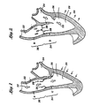
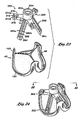
- the primary sub-assemblies of a preferred embodiment of the prosthetic heart valve 40 of the present invention are shown in exploded view.
- the directions up and down, upper and lower, or top and bottom, are used with reference to Figure 3, but of course the valve can be oriented in any direction both prior to and after implantation.
- the heart valve 40 comprises a group 41 of three leaflets 42, three angled alignment brackets 44, a stent assembly 46, and a connecting band 48.
- Each of the sub-assemblies seen in Figure 3 is procured and assembled separately (except for the group of leaflets, as will be explained), and then joined with the other sub-assemblies to form the fully assembled valve 40 as seen in Figure 11.
- the prosthetic valve 40 is a trifoliate valve with three leaflets 42. Although three leaflets are preferred, and mimic the natural aortic valve, the principles of the present invention can be applied to the construction of a prosthetic valve with two or more leaflets, depending on the need.
- Each of the sub-assemblies seen in Figure 3 include three cusps separated by three commissures.
- the leaflets 42 each include an arcuate lower cusp edge 50 terminating in upstanding commissure regions 52.
- Each leaflet 42 includes a coapting or free edge 54 opposite the cusp edge 50.
- the stent assembly 46 also includes three cusps 60 separated by three upstanding commissures 62.
- the connecting band 48 includes three cusp portions 64 separated by three upstanding commissure portions 66.
- the stent assembly 46 comprises an inner stent 70 and an outer cloth cover 72. More specifically, the inner stent 70 desirably includes three identical and separate stent members 74, each of which has a separate cloth covering. As seen best in Figure 4B, each stent member 74 comprises an arcuate lower cusp region 76 and upstanding commissure regions 78 each terminating at a tip 80.
- the stent members 74 comprise elongate rods or wires, preferably made out of an elastic biocompatible metal and/or plastic alloy, such as Elgiloy®, Nitinol, polypropylene, etc..
- the material selected for stent members 74 should be elastic to permit flexing along their lengths, but should possess a relatively high modulus of elasticity to avoid asymmetric deformation of the constructed valve 40.
- the stent 70 supplies an inner frame for the valve 40 that is relatively more rigid than the other components. Therefore, the stent 70 acts to limit total flexibility of the valve 40.
- the stent members 74 are desirably bent into the illustrated shape, using conventional wire-forming techniques. Each of the stent members 74 is identical, and terminates in the tips 80 which are bent inward with respect to the arcuate cusp regions 76 to nearly form closed circles. As is seen in Figure 4B, a gradual radially outward bend 82 (with respect to the cylindrical stent 70) is provided in the stent members 74 at a transition between each of the commissure regions 78 and the intermediate cusp region 76. This bend 82 permits each of the stent members 74 to remain in a circular configuration, as seen from above in Figure 4A.
- each of the cusp regions 76 includes a lower apex 84, and the apices of all of the cusps define a circle concentric with and having the same diameter as a circle defined by all of the tips 80.
- the stent 70 thus defines a substantially cylindrical volume therewithin.
- other volumes may be defined by the stent 70 wherein the tips 80 define a circle that is smaller or larger than a circle defined by the apices 84.
- the apices 84 may be provided outward from the tips 80 so the stent 70 defines a frusto-conical volume therewithin.
- each of the stent members 74 is preferably covered with a generally tubular cloth 72 from tip to tip 80.
- the cloth cover 72 is a biocompatible fabric, such as polyterephthalate, and has a varying cross sectional shape, as indicated in Figures 6A and 6B. More specifically, the cloth cover 72 includes a tubular portion closely conforming around each of the stent members 74 and a flap 86 extending radially outward from the stent member (with respect to the curvature of the cusp regions 76).
- the cloth cover 72 is formed by wrapping an elongated sheet of fabric around each of the stent members 74 and joining the free edges with sutures 88 to form the flaps 86.
- the flap 86 extends from each stent member 74 in a direction that is generally outward with respect to the cusp region 76, and continues in the same general orientation up the commissure regions 78 to the tips 80.
- the flap 86 has a dimension that is longest at the apex 84 of each cusp region 76 and shortest at the tips 80. Indeed, the flap 86 is preferably nonexistent at the tips 80, and gradually increases in size from the tip 80 to the apex 84. Therefore, the cross-section of Figure 6A taken through the commissure region 78 shows the flap 86 having a small dimension d1, and the cross-section of Figure 6B taken through the apex 84 shows the flap 86 having a longer dimension d2.
- the final component of the stent assembly 46 is an attachment means 90 for joining each of a cloth-covered stent members 74.
- the attachment means 90 comprises threads or sutures sewn through the central holes in each of the circular tips 80, as shown in Figure 5, although other suitable attachment means could be used, such as rings, cinches, or the like.
- the attachment means 90 may be wrapped around or sewn through the cloth cover 72.
- the attachment means 90 are desirably not wrapped extremely tightly, but are instead provided with some slack to permit relative movement of the tips, as will be described below.
- the stent 70 When the stent members 74 are attached, as seen in Figure 5, the stent 70 exhibits three cusps corresponding to the cusp region 76 of each member, and three upstanding commissures defined by the juxtaposition of adjacent pairs of commissure regions 78.
- the attachment means 90 comprises a non-bioresorbable material to ensure that the individual stent members 74 are maintained in the shape of the stent 70.
- the attachment means 90 comprises a bioresorbable material that dissolves over a period of time after implantation.
- the natural host tissues may have grown in and around the porous portions of the valve 40 to help retain the original shape of the stent 70. In some instance, however, very little tissue overgrowth may have occurred prior to the attachment means 90 dissolving, and the individual stent members 74 are permitted to move radially a great deal with respect to one another.
- the connecting band 48 may be re-configured to be non-continuous at the commissure portions 66 (see Figure 3).
- each individual stent member 74 and associated leaflet 72 moves entirely independently of the others, albeit all oscillating with the natural contractions and expansions of the surrounding aortic wall.
- Such independent leaflet movement may greatly reduce any potential pressure drop across the valve.
- one embodiment is to provide a bioresorbable attachment means 90 such as the sutures shown in the embodiment of Figure 5, those of skill in the art will understand that any of the coupling means connecting the individual stent members 74 disclosed in the present application could be modified to resorb over time.
- the stent assembly 46 provides an inner support frame that is generally rigid along any one of stent members 74, but which permits the stent members to move with respect to one another.
- “generally rigid” refers to the structural strength of the stent members 74 that is sufficient to maintain the general shape of the stent 70, but that permits some flexing along the length of the stent members.
- the stent members 74 are generally rigid, they are able to move with respect to one another. More particularly, joining the stent members 74 with the attachment means 90 creates nodes or pivot points of the valve 40 at the commissures 62 of the stent assembly 46.
- the stent members 74 are permitted to pivot with respect to one another as they move radially inward and outward. Inward pivoting is permitted by spaces 94, seen in Figure 5, defined between adjacent cloth-covered commissure regions 78 of each stent member 74. These regions 94 are generally triangular and gradually increase in size from the attached commissure tips to the diverging cusps.
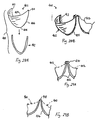
- Figures 7A, 7B, and 7C are plan views of various configurations of leaflets 42 suitable for use in the prosthetic heart valve 40.
- Figure 7A shows a leaflet 42 having the aforementioned cusp 50, commissure regions 52, and free edge 54.
- the coapting edge 54 comprises two linear portions extending from an apex 100 to outer tips 102.
- the two portions of the free edge 54 are angled with respect to one another and define sides of a triangular region 104 having as its hypotenuse an imaginary line 106 extending between the opposed tips 102.
- the triangular region 104 of each leaflet 42 is under less tension during dynamic motion of the valve 40, and helps ensure coaptation of the leaflets.
- an imaginary (dashed) fold line 108 defines an outer margin 110 of the leaflet 42 that is used to secure the leaflets into the valve 40.
- the margins 110 are sutured between the stent assembly 46 and connecting band 48 ( Figure 3), and the free edge 54 of the leaflet extends across the cylindrical region defined within the valve 40, and is generally free to move in that region. Because the triangular leaflet region 104 is relatively stress-free, it tends to roll over under the influence of fluid dynamic forces, thus helping the three leaflets to coapt and prevent valve insufficiency.
- FIG. 7B shows a leaflet 112 that is substantially the same as the leaflet 42 of Figure 7A, and thus like elements will be given the same numbers.
- the leaflet 112 includes a pair of generally triangular shaped commissure tabs 114 in the commissure regions 52. The tips 102 are thus spaced farther apart than in the version shown in Figure 7A.
- the commissure tabs 114 are used to more securely fasten each of the leaflets to the commissures 62 of the stent assembly 46 ( Figure 3).
- the cloth cover 72 of the stent assembly 46 includes a flap 86 ( Figure 5) which diminishes in size in the commissure regions.
- the tabs 114 are thus wrapped farther around the cloth-covered stent assembly 46 in the commissure regions and sutured thereto, thus facilitating a more durable connection.
- FIG. 7C is a further variation of a leaflet 116 which is, again, the same in all respects to the leaflets described above, except for somewhat trapezoidal-shaped commissure tabs 118. Again, the commissure tabs 118 help to secure the leaflets 116 in the prosthetic valve 40.
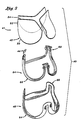
- Figure 8 illustrates a stent/leaflet sub-assembly 120 in which the leaflets 42 are secured to the stent assembly 46.
- leaflets 42 are pre-attached to align the free edges 54.
- the free edges 54 of each two adjacent leaflets 42 extend outward in juxtaposition and are received within the triangular space 94 defined between the commissure regions 78 of the stent assembly 46 ( Figure 5).
- the group of leaflets 41 is thus "inserted” underneath the stent assembly 46 until the juxtaposed free edges 54 of the leaflets 42 are in close proximity below the attachment means 90.
- the outer margin 110 of each leaflet 42 is folded underneath the corresponding cusp 60 of the stent assembly 46.
- sutures or other such means attach the margins 110 to the flap 86 of the stent assembly 46.
- the leaflets 42 can remain attached to one another at their adjacent tips 102 (or along the free edges 54 near the tips), or can be separated for maximum valve flexibility or when the stent is designed to separate into individual stent members by bio-resorption of a commissure couple.
- leaflets 112 or leaflet 116 of Figure 7B or 7C are used, the respective commissure tabs 114 or 118 are wrapped around the adjacent part of the stent assembly 46 and secured thereto.
- the leaflets 42 are simply retained in position with respect to the stent assembly 46 with temporary sutures or other such means, to permit the stent/leaflet subassembly 120 to be finally joined together with the connecting band 48 of Figure 8.
- Figure 8 also illustrates the three alignment brackets 44 and that each has a generally L-shaped cross-section and comprises a cloth-covered inner member (not separately numbered).
- the inner member preferably has minimum elasticity, but is relatively thin and lightweight.
- One preferred material for the inner member is a polyester film such as Mylar®.
- the brackets 44 are preferably joined to the valve 40 at the time the stent/leaflet sub-assembly 120 and connecting band 48 are joined, and thus will be described more fully below with respect to Figure 11.
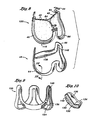
- Figures 9 and 10 illustrate the connecting band 48 in more detail, comprising an inner member 130 surrounded by a cloth cover 132.
- the connecting band 48 includes three cusp portions 64 alternating with commissure portions 66, all generally formed in a tubular configuration. This shape is provided by the inner member 130, with the cloth cover 132 simply draped and sewn thereover.
- the inner member 130 is molded of silicone rubber, and the cloth cover 132 is polyterephthalate.
- the inner member 130 has a varying cross sectional shape along the cusps and commissures.
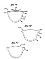
- Figure 10 is cross-section through one of the cusp portions 64 of the connecting band 48, and shows a region of the inner member 130 having an inner ledge 134 and upwardly angled outer free margin 136.
- the cloth-covered ledges 134 extend generally radially and define three stent support regions 138 of the connecting band 48, as seen in Figure 8.
- the ledge 134 has its greatest radial dimension at the midpoint of each of the cusp portions 64 and gradually tapers down in size toward the commissure portions 66.
- the free margins 136 form their greatest outward angle with respect to a central axis of the connecting band 48 at each cusp portion 64, and gradually re-align to be parallel to the central axis in the commissure portions 66.
- the cross-section of the inner member 130 at the commissure portions 66 is seen in Figure 12B.
- a series of triangular shaped ribs 140 projects outward from the inner member 130.
- the ribs 140 are formed around the entire inner member 130, along both the cusp and commissure regions.
- the commissure portions 66 of the connecting band 48 define generally axial gaps 142 that help permit flexing of the valve 40.
- the connecting band 48 may be discontinuous at the commissure portions 66 if the valve has bioresorbable commissures and is designed to separate into individual "leaflets.”
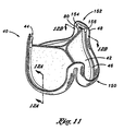
- FIG 11 illustrates the assembled valve 40 in perspective
- Figures 12A and 12B show cross-sections through a valve cusp 150 and valve commissure 152, respectively.
- the connecting band 48 is sewn or otherwise attached to the exterior of the stent/leaflet subassembly 120.
- the connecting band 48 is attached underneath the stent/leaflet subassembly 120 in the cusp 150, but the free margins 136 of the connecting band are positioned to the outside of the subassembly.
- the alignment brackets 44 are installed with a vertical leg 156 interposed between the commissures 62 of the stent assembly 46 and the commissure portions 66 ( Figure 3) of the connecting band 48.
- a horizontal leg 154 of each of the alignment brackets 44 projects radially inward to cover the tips 80 of the stent assembly 46.
- the alignment brackets 44 help hold each two adjacent tips 80 of the three-piece stent 70 together, especially helping to prevent radial misalignment.
- the brackets also provide flat surfaces which a holder can contact, as seen best in Figure 26.
- the sandwiched configuration of the stent assembly 46, leaflet 42, and connecting band 48 can be seen. More specifically, the cloth flap 86 of the stent assembly 46 aligns with the leaflet margins 110, which in turn rest on the stent supports 138. A series of suture stitches 158 are used to secure these elements together. Preferably, the flap 86 terminates at the same location as the margin 110 of each leaflet 42, and at the corner defined in the connecting band 48 between each ledge 134 and free margin 136. The radially innermost wall of the ledge 134 is preferably inward from the stent member 74. This construction helps prevent the stent 70 from migrating downward with respect to the connecting band 48.
- the host annulus 162 is seen in phantom with the aortic wall 164 continuing upward therefrom. It can be readily seen that the angled shape of the cusp portions 64 of the connecting band 48 conform nicely to the host annulus region.
- the triangular ribs 140 provide volume at the free margins 136 of the connecting band 48 to facilitate connection to the natural tissue; in other words, more volume provides more of a "bite" for the surgeon to secure the band 48 with a suture needle.
- sutures which are not shown, the present invention should not be construed as limited to being implanted with sutures and other means such as staples, adhesives, and the like could be used.
- FIG. 12B the assembly of the valve components in the commissure region is seen.
- the commissure edges 52 of each of the leaflets 42 are sandwiched in between the stent assembly 46 and connecting band 48. More particularly, the commissure edges 52 are sandwiched between the flaps 86 and the generally planar commissure portions 66 of the connecting band 48 ( Figure 8). Sutures 170 are provided to join these elements together. Again, the commissure edges 52 preferably terminate at the same location as the flaps 86.
- Figure 12B also illustrates the gap 142 provided in the commissure regions of the connecting band 48, and the lack of structural connection between the two sides of each valve commissure 152.
- Figure 12B shows in phantom a portion of the aortic wall 172 to which the commissures 152 of the valve 40 are attached. Again, the particular attachment means is not shown, but the connecting band 48 is traditionally sutured to the wall 172.
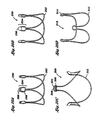
- Figures 13 and 15 illustrate a conduit portion of a heart in the region of the aortic valve and relative motions of the conduit walls during systole and diastole, respectively.
- Figure 13 shows an open valve 200 and systolic blood flow 202
- Figure 15 shows a closed valve 204 and diastolic back flow of blood 206.
- the regions around the aortic valve can be generally separated into an annulus region 208 and a sinus region 210.
- the annulus region 208 is expected to contract during the systolic phase, as indicated by the arrows 212 in Figure 13, and expand during the diastolic phase, as indicated by the arrows 214 in Figure 15.
- the sinus region 210 is expected to expand during the systolic phase, as indicated by the arrows 216 in Figure 13, and is expected to contract during the diastolic phase, as indicated by the arrows 218 in Figure 15.
- the movements of the conduit walls are shown with respect to a neutral or relaxed position 220, and may be exaggerated from the true movements. Also, as mentioned above, these movements are educated guesses and may be different for some, if not most patients. However, the flexible heart valve of the present invention accommodates all variations of such movements.
- Figures 14 and 16 schematically illustrate the synchronous movement of the prosthetic valve 40 of the present invention with respect to the movements of the host tissue in systolic and diastolic phases as seen in Figures 13 and 15.
- Figures 14 and 16 only illustrate the stent 70 of the present invention, which as previously described acts as a limitation to movement of the entire valve 40 and fairly represents movement of the entire valve.
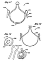
- FIGs 17-19 illustrate an alternative stent assembly 250 comprising an inner stent 252 and an outer cloth cover 254.
- the stent assembly 250 includes alternating cusps 256 and commissures 258.
- the stent 252 includes three separate stent members 260 having arcuate commissure tips 262 that are curved toward one another.
- a generally disk-shaped commissure housing 264 encompasses the adjacent commissure tips 262, retaining the stent members 260 together while permitting relative pivoting.
- FIG 19 illustrates two adjacent commissure tips 262 and the commissure housing 264 exploded into a male housing portion 266 and a female housing portion 268.
- the housing portions are so named because they are joined together through interference between a button 270 of the male housing portion 266 and an aperture 272 on the female housing portion 268.
- Each portion of the commissure housing 264 includes a circular groove 274 for receiving the arcuate tips 262.
- the grooves 274 combined to form a circular channel having an axis 276 within which the arcuate tips 262 are received and can slide. When assembled together, the commissure housings 264 thus provide nodes of rotation for each of the stent members 260.
- FIG 20A illustrates an alternative stent 280 suitable for use in a heart valve of the present invention.
- the stent 280 includes three stent members 282, each having commissures with a flex region 284 and tips 286.
- the tips 286 of adjacent stent members 282 are secured together by sutures or other suitable means (not shown).
- the flex regions 284 comprise sections of each stent member 282 which are bent away from each other.
- the stent members 282 can thus pivot with respect to one another about the connected tips 286.
- a fulcrum 288 is created by interaction between the stent members at the lower end of the flex region 284.
- the relative flexibility in inward or outward movement of the stent members 282 can be modified by selection of the cross sectional size and shape of the stent members, and overall configuration of the flex region 284.
- FIG 20B illustrates a second alternative stent 290 suitable for use in a heart valve of the present invention.
- the stent 290 includes three wires 292 and has commissure regions 294 formed by bent ends of the wires and a junction member 296.
- the junction member 296 either rigidly holds the terminal ends of each of the wires 292, or permits the wires to slide or otherwise flex with respect to one another. If the wires are rigidly attached to the junction member 296 the shape of the wires in the commissure region 294 reduces stress risers in bending.
- FIG. 20C illustrates a third alternative stent 300 suitable for use in a heart valve of the present invention.
- the stent 300 comprising three separate wires 302 terminating at circular commissure tips 304.
- Each of the commissure tips 304 is rotatably fastened around a pin 306 provided on a junction plate 308 common to adjacent wires 302. In this manner, the tips 304 remained located close to one another, while the cusps of the wires 302 can pivot in and out.
- FIG 20D illustrates a fourth alternative stent 310 suitable for use in a heart valve of the present invention.
- the stent 310 is made in one piece with a series of alternating cusps 312 and commissures 314.
- the commissures 314 comprising a nearly 360° bend in the stent 310 which permits each cusp 312 to easily flex with respect to the other cusps.
- FIG 20E illustrates a fifth alternative stent 320 suitable for use in a heart valve of the present invention.
- the stent 320 comprises three wire-like stent members 322, adjacent ones of which are joined together at commissure regions 324 by a U-shaped coupling 326 and a pair flexible sleeves 328.
- Figure 21 is a detail of one of the commissure regions 324 showing in hidden lines the adjacent ends of the coupling 326 and stent members 322.
- the couplings 326 are preferably sized with the same diameter as the stent members 322, and the sleeves 328 are tubular with a constant diameter lumen.
- the sleeves 328 may be made of silicone, or a flexible polymer such as polyurethane or the like. Other flexible interfaces such as sleeves 328 are contemplated, such as, for example, a single block of silicone into which the commissure regions 324 of the stent members 322 are molded.
- Figure 22 is a detailed view of a commissure region 330 of a still further alternative stent suitable for use in a heart valve of the present invention.
- the stent is made in one piece with adjacent cusps 332 being joined by a coil spring tip 334. Again, great flexibility is provided by the coil spring tips 334 to enable relative motion of the cusps 332.
- the amount of flexibility is selected as in any spring by varying the material, cross-sectional size and shape, and number of turns of the spring.
- Figures 23-26 illustrate a preferred holder 350 useful for implanting the flexible heart valve 40 of the present invention.
- the holder 350 must provide adequate support to insure a stable platform for the surgeon to position the valve for attachment to the natural tissue.
- the holder 350 desirably provides rigid structure for maintaining a fixed shape of the valve during implantation.
- the holder 350 must include structure to allow quick release from the valve 48 after the valve is implanted.
- the holder 350 comprises a proximal handle socket 352 having an inner bore 354 for receiving the distal end of a handle (not shown).
- the socket 352 may be provided with internal threads, or other such quick-release coupling structure to facilitate handle connection and disconnection.
- the holder 350 has three radially outwardly-directed commissure legs 356, and three outwardly and downwardly angled cusp legs 358. Consistent with the distribution of the cusps 150 and commissures 152 of the valve 40, the commissure legs 356 are oriented 120° apart, and the cusp legs 358 are oriented 120° apart, with the three commissure legs being offset with respect to the three cusp legs by 60°.
- each of the commissure legs 356 extends outward from the handle socket 352 into proximity with one of the valve commissures 152 and is secured thereto with an upper suture 360.
- each of the cusp legs 358 extends outward and downward from the handle socket 352 into proximity with a midpoint of one of the valve cusps 150, and is secured thereto with a lower suture 362.
- the lower end of each cusp leg 358 includes a concavity for mating with the corresponding rod-like stent member 74, as seen in Figure 26. In this manner, each of the cusps 150 and commissures 152 of the valve 40 is securely held in relation to the others, thus facilitating implantation by the surgeon.
- Each commissure leg 356 extends outward from the handle socket 352 in a generally rectangular cross-section interrupted by an upwardly-facing inner notch 370 oriented cross-wise to the leg. And upwardly-facing radial channel 372 having a depth of approximately half of each commissure leg 356 extends from about the inner notch 370 to the outermost end of the leg.
- the inner notch 370 is not quite as deep as the channel 372, as seen in Figure 26.
- the radial channel 372 divides the upper portion of each commissure leg 356 into two walls 374a, 374b.
- An eyehole 376 is formed in one of the walls 374a, and a corresponding outer notch 378 is formed in the other wall 374b aligned with the eyehole.
- the outer notch 378 is also not quite as deep as the channel 372.
- the upper suture 360 is preferably tied to the eyehole 376 in the first wall 374a.
- the suture 360 then passes across the channel 372, through the outer notch 378, and is passed along the inner notch 370, again traversing the channel 372.
- the suture 368 is then passed through a suture-permeable portion of the valve commissure 152, such as through the connecting band 48.
- the suture 360 is again looped through one or both of the notches 370, 378 and retied to the eyehole 376.
- each commissure 152 can be secured to the commissure leg 356 and easily released by inserting a scalpel blade into the radial channel 372 to sever the portions of the suture therein.
- each cusp leg 358 can be seen in Figures 23 and 26.
- a pair of longitudinal rails 380a, 380b are provided on the outer side of each cusp leg 358.
- a pair of aligned eyeholes 382 provide anchoring locations for the lower suture 362.
- a scalpel guide or relief 384 is formed in one of the rails 380b.
- the lower suture 362 extends downward from the eyeholes 382, passes through a suture-permeable portion of the cusp 150, and is then returned and secured to the eyeholes 382.
- the relief 384 exposes a portion of the lower suture 362 for severing by the surgeon using a scalpel blade. It will thus be understood that the holder 350 can be quickly released from the valve 40 by a series of six scalpel strokes, with each of the sutures 360, 362 remaining attached to the holder 350 and being withdrawn from the valve 40 as the holder is withdrawn.
- FIGS 27A and 27B illustrate an alternative holder 390 useful for implanting the flexible heart valve 40 of the present invention.
- the holder 390 is substantially similar to the holder 350 described above, but the ends of each of a plurality of rigid legs for attaching to the valve cusps are flared, or, more precisely, each lower leg has a width from a hub to a terminal end that is greatest at the terminal end to provide more surface area to contact the corresponding valve cusp. That is, the holder 390 includes a plurality of upper legs 392 having a generally constant width, and a plurality of lower legs 394 having flared ends 396, the legs extending from a central hub 398.
- the upper legs 392 extend radially outward to connect to the valve commissures 152, and the lower legs 394 angle radially outward and downward to connect to the valve cusps 150.
- the flared ends 396 impart greater stability to the flexible valve 40 during implantation, especially helping to prevent movement of the cusps 150.
- the legs 194 remain fairly narrow until the flared ends 396 to maintain good visibility through the spaces between the plurality of legs. That is, for example, the surgeon can continue to view the valve leaflets 42 between the legs as a check on valve orientation.
- a further aspect of the invention is a heart valve having three leaflets directly sutured to the aortic annulus wherein the commissures of adjacent leaflets are totally or partially independent, and may be connected during implant but will become independent thereafter. This gives the independent leaflets and juxtaposed commissures full freedom to move during systole and diastole, thus reducing the pressure gradient.
- any of the stent assemblies described herein may include separate stent members initially coupled together with a permanent or bioresorbable fastener, the latter dissolving after a fairly short amount of time to permit independent movement of the leaflets.
- the present invention discloses an independent leaflet and implantation device that can replace a single defective leaflet, with the prosthetic leaflet functioning in conjunction with the remaining native leaflets.
- an independent leaflet 400 seen in Figures 28A and 28B includes a planar or three-dimensional body 402 defined by a coapting edge 404 and a fixation edge 406.
- the fixation edge 406 includes an arcuate cusp region 408 and a pair of commissure regions 410.
- the body 402 is attached along its fixation edge 406 to an arcuate flexible support 412 that preserves the shape of the fixation edge and provides a platform for attachment to the native tissue.
- Figure 28B shows the leaflet 400 attached to a native annulus 422 adjacent a native leaflet 423.
- the leaflet body 402 may be made from a biological material such as a porcine valve leaflet or a piece of bovine pericardium, chemically or physically treated to prevent immunological reaction and fatigue.
- the leaflet body 402 may be formed of a synthetic material such as a polymer or a woven fabric.
- the flexible support 412 is desirably made of a synthetic material, for example silicone or PTFE.
- the independent leaflet 400 may be used with other such leaflets, preferably three total, that are attached directly to an ascending aorta and function together as a prosthetic valve. That is, as seen in Figure 29A, adjacent flexible supports 412 may be attached at their juxtaposed commissure regions with a separate fastener 414, such as a clip.
- the clip 414 may be permanent or bioresorbable. Regardless of its longevity, the clips 414, when securing the leaflets 400 together, permit the leaflets to flex with respect to one another so as to allow the assembled valve to move in synch with the native tissue during the sytole/diastole cycle. This, in turn, reduces the pressure gradient through the valve.
- FIG 29B illustrates an alternative fastener between independent leaflets in the form of a continuous scalloped wire or stent 416.
- Each leaflet 400 (either the leaflet body 402 directly or via the support 412) is attached to the scalloped stent 416 and thus functions together with the other leaflets in a prosthetic valve.
- the embodiment in Figure 29B is similar to those previously described, wherein the scalloped stent 416 is highly flexible and permits both cusp and commissure movement. Again, however, the commissure regions 418 of the stent 416 may be bioresorbable to result in completely independent leaflets after a period of time in the body.
- Figure 30 is a perspective view of an exemplary independent leaflet measuring device 420 used to select the appropriate leaflet 400 according to the size and geometry of the native annulus 422.
- the device 420 includes a handle 424 and an arcuate leaflet sizer 426 that is sized and shaped to match the prosthetic leaflet.
- Two or more struts 428 may extend between the handle 424 and sizer 426 to improve stability in rotation and manipulation of the sizer.
- FIGS 31A-31C are schematic views of a device 440 for automatically implanting an independent leaflet of the present invention, illustrating an articulated holder especially suited for minimally invasive environments.
- the device 440 includes a handle 442 connected to the independent leaflet 444 via a leaflet holder 446, comprising a plurality of movable struts 446.
- the struts 446 pivot or slide with respect to one another to convert the device from the low-profile configuration shown in Figure 31 A capable of passing through small apertures, to the full deployment configuration of Figure 31C.
- the leaflet 444 may be attached to the leaflet holder 446 with sutures or the like.
- a plurality of staples 448 are provided extending outward from the leaflet fixation edge that pierce the native tissue and are deformed by a backing tool or assume a bent shape upon a temperature change.
- the final configuration is seen in Figure 31 C, and those of skill in the art will appreciate the ease of use of the separate leaflet implantation procedure. Once implanted, any structure connecting the leaflet 444 to the device 440 is severed, and the device removed.
- FIGs 32A-32C are schematic views of a still further exemplary implantation device for the independent leaflet embodiment.
- the device includes an anvil or backing portion 460 having a handle 462 and a plurality of fluid-carrying tubes 464 through which a cold or warm fluid can circulate, as seen by the arrows 466.
- the circulating fluid regulates the temperature of the tubes 464 during implantation.
- the device further includes a holder 470, similar to the holder 440 of Figure 31A, to which an independent leaflet 472 is temporarily attached, such as with sutures 474.
- the fluid-carrying tubes 464 of the backing portion 460 is placed below the native annulus 476 while the leaflet holder 470 is maneuvered into position above the annulus.
- Opposite displacement of the backing portion 460 and holder 470 causes a plurality of staples 478 to pierce the annulus 476 and be deflected or otherwise curled by the tubes 464.
- the staples 478 are shape memory alloy materials like Nitinol, the fluid circulating through the tubes 464 can be used to cause a temperature-induced shape change.
- Figure 33 is a cross-sectional view through one embodiment of an attachment structure for the independent leaflet embodiment.
- the structure includes staples 480 that extend outward from a leaflet fixation edge 482 through the native tissue 484, and curl or bend into a shape that prevents removal.
- the curling of the staples 480 may be accomplished using the device 460 (i.e., the backing portion 460 and holder 470) that provide a backing plate or anvil, or through a temperature change, such as when a shape memory material is used.
- the staples 480 may include adjacent legs that curl at different lengths to accommodate one another. Exemplary dimension are shown in Figure 33, with the width of the leaflet fixation edge 482 being about 9 mm, the length of one leg of each staple 480 being about 8 mm, and the length of one leg of each staple 480 being about 10 mm.
Claims (38)
- Valvule cardiaque prothétique (40), comprenant:un stent cylindrique généralement flexible (46 ; 250; 280; 290; 300; 310 ; 320) présentant en alternance des lames valvulaires (60) et des commissures (62) ;une pluralité de valves flexibles (42) fixées au stent de façon à former une valvule à sens unique dans le cylindre ; etune bande flexible (48) fixée le long du stent et présentant un bord libre s'étendant vers l'extérieur à partir du stent le long des lames valvulaires et commissures en alternance pour relier la valvule cardiaque à un orifice anatomique;dans laquelle le stent comprend une pluralité d'éléments séparés (74) disposés généralement en un cercle pour définir le volume cylindrique, chaque membre comprenant une partie de lame valvulaire arquée (84) et deux parties de commissure montantes (78) ; et dans laquelle chaque paire de parties de commissure d'éléments adjacents est juxtaposée pour définir chaque commissure de stent, caractérisée en ce que le stent comprend des moyens destinés à relier de manière non rigide les éléments de stent les uns aux autres au niveau des paires juxtaposées de parties de commissures pour permettre le déplacement relatif des éléments de stent adjacents au niveau des commissures du stent.
- Valvule cardiaque (40) selon la revendication 1, dans laquelle le stent (46) est fixé à la pluralité de valves flexibles (42) pour définir un sous-ensemble formant stent-valve.
- Valvule cardiaque (40) selon l'une ou l'autre des revendications 1 et 2, dans laquelle le stent (46) est configuré pour permettre aux lames valvulaires (60) et aux commissures (62) de se déplacer radialement vers l'intérieur et vers l'extérieur.
- Valvule cardiaque (40) selon l'une ou l'autre des revendications 1 et 2, dans laquelle le stent (46) comprend une structure de type tige recouverte de tissu (74).
- Valvule cardiaque (40) selon la revendication 5, dans laquelle l'enveloppe en tissu (72) entoure étroitement la structure de type tige (74) et présente un volet (86) se projetant vers l'extérieur à partir de celle-ci sensiblement sur toute la longueur des lames valvulaires (60) et des commissures (62) pour la liaison à la bande (48) et aux valves (42).
- Valvule cardiaque (40) selon l'une ou l'autre des revendications 1 et 2, dans laquelle la bande (42) comprend un élément interne perméable aux sutures (70) et une enveloppe externe en tissu (72), la bande présentant des parties de lame valvulaire (64) et des parties de commissure (66) continues.
- Valvule cardiaque (40) selon la revendication 6, dans laquelle l'élément interne perméable aux sutures (70) comprend une structure en silicone moulée.
- Valvule cardiaque (40) selon la revendication 6, dans laquelle la bande (48) comprend une série de nervures de renforcement parallèles (140) se projetant vers l'extérieur s'étendant en continu le long de l'ensemble des parties de lame valvulaire (64) et des parties de commissure (66) de la bande.
- Valvule cardiaque (40) selon la revendication 6, dans laquelle les parties de commissure (66) de la bande (48) sont généralement planaires et alignées axialement, et les parties de lame valvulaire (64) de la bande comprennent chacune une partie inclinée vers l'extérieur (136) et un épaulement incliné vers l'intérieur (134).
- Valvule cardiaque (40) selon la revendication 9, dans laquelle l'épaulement incliné vers l'intérieur (134) de chaque partie de lame valvulaire (64) de la bande (48) s'étend vers l'intérieur sur une distance suffisante pour supporter la lame valvulaire correspondante (60).
- Valvule cardiaque (40) selon l'une ou l'autre des revendications 1 et 2, dans laquelle la bande (48) comprend des parties de lame valvulaire arquées (64) épousant généralement les lames valvulaires (60), et la bande comprend des parties de commissure (66) entre elles chacune présentant une forme de U inversée pour définir un espacement s'ouvrant vers le bas (142) qui augmente la flexibilité de la valvule en permettant le déplacement relatif de la lame valvulaire.
- Valvule cardiaque (40) selon la revendication 1, dans laquelle les lames valvulaires (60) de la valvule sont reliées les unes aux autres de manière articulée.
- Valvule cardiaque (40) selon la revendication 1, dans laquelle chaque paire de parties de commissure (62) est reliée avec des sutures (158) pour permettre le déplacement relatif des parties de lame valvulaire adjacentes (60).
- Valvule cardiaque (40) selon la revendication 1, dans laquelle chaque partie de commissure (62) est reliée pour pivoter autour d'un premier axe qui est fixe par rapport à un second axe autour duquel pivote la partie de commissure adjacente.
- Valvule cardiaque (40) selon la revendication 14, dans laquelle les premier et second axes sont coïncidents.
- Valvule cardiaque (40) selon la revendication 15, dans laquelle chaque partie de commissure (62) se termine au niveau d'une extrémité arquée (262), la valvule comprenant en outre des éléments de couplage présentant à l'intérieur des canaux arqués, les éléments de couplage (266 ; 268) recevant les extrémités arquées des parties de commissure et permettant le glissement relatif autour d'un axe de pivotement défini par le canal arqué.
- Valvule cardiaque (40) selon la revendication 14, dans laquelle chaque partie de commissure (62) se termine au niveau d'une extrémité généralement circulaire (304), la valvule comprenant en outre des éléments de couplage (308) présentant dessus une paire de broches espacées (306), qui définissent les premier et second axes et autour desquelles pivotent les extrémités circulaires de chaque partie de commissure.
- Valvule cardiaque (40) selon la revendication 1, dans laquelle la valvule comprend une pluralité d'éléments de couplage pliables (328) chacun se couplant à une paire de parties de commissure adjacentes (324) pour permettre le déplacement relatif entre elles.
- Valvule cardiaque (40) selon la revendication 18, dans laquelle chaque partie de commissure (324) se termine au niveau d'une extrémité généralement linéaire (326), les éléments de couplage pliables (328) comprenant des manchons tubulaires pliables s'adaptant de manière serrée sur les extrémités linéaires.
- Valvule cardiaque (40) selon la revendication 1, dans laquelle les moyens pour relier les éléments de stent (74) entre eux comprennent des sutures (158).
- Valvule cardiaque (40) selon la revendication 1, dans laquelle les moyens pour relier les éléments de stent (74) entre eux comprennent une interface en matériau flexible.
- Valvule cardiaque (40) selon la revendication 1, dans laquelle les moyens pour relier les éléments de stent (74) entre eux comprennent une structure biorésorbable.
- Valvule cardiaque (40) selon la revendication 1, dans laquelle le stent (46) comprend une structure de type tige enveloppée de tissu (74).
- Valvule cardiaque (40) selon la revendication 23, dans laquelle l'enveloppe en tissu (72) entoure de manière étroite la structure de type tige (74) et présente un volet (86) se projetant vers l'extérieur à partir de celle-ci sur sensiblement toute la longueur des lames valvulaires (60) et des commissures (62).
- Valvule cardiaque (40) selon la revendication 24, dans laquelle le volet (86) présente une largeur qui varie le long des lames valvulaires (60) et des commissures (62) du stent (46), le volet étant plus étroit dans les lames valvulaires.
- Valvule cardiaque (40) selon la revendication 24, dans laquelle la bande flexible (48) est fixée le long du volet (86) du stent.
- Valvule cardiaque (40) selon la revendication 26, dans laquelle les bords (50) de lame valvulaire des valves (42) sont fixés entre la bande (48) et le volet (86) du stent.
- Valvule cardiaque (40) selon la revendication 26, dans laquelle la bande (48) présente des lames valvulaires (60) et des commissures (62) continues, les lames valvulaires de la bande comprenant chacune une partie inclinée vers l'extérieur (136) et un épaulement incliné vers l'intérieur (134) s'étendant vers l'intérieur sur une distance suffisante pour supporter la lame valvulaire correspondante du stent (46).
- Valvule cardiaque (40) selon la revendication 23, dans laquelle la structure de type tige (74) est fabriquée dans un polymère.
- Valvule cardiaque (40) selon la revendication 1, dans laquelle chaque élément séparé (74) est enveloppé de tissu séparément.
- Valvule cardiaque (40) selon la revendication 30, dans laquelle chaque partie de commissure montante (78) se termine au niveau d'une extrémité pliée sensiblement circulaire (326), les extrémités adjacentes et pliées de chaque élément séparé étant juxtaposées et suturées les unes aux autres à travers les enveloppes en tissu (72) respectives.
- Valvule cardiaque (40) selon la revendication 1, dans laquelle chaque valve (42) comprend un bord de lame valvulaire arqué (50) se terminant au niveau d'extrémités externes reliées aux commissures (62) du stent (46), et un bord rapprochant qui est défini par les deux lignes relativement inclinées se rencontrant à un sommet à mi-chemin entre les deux extrémités (102).
- Valvule cardiaque (40) selon la revendication 32, dans laquelle chaque valve (42) est composée de tissu péricardique.
- Valvule cardiaque (40) selon la revendication 32, dans laquelle les bords de lame valvulaire arqués (50) deviennent progressivement asymptomatiques aux extrémités (102).
- Valvule cardiaque (40) selon la revendication 32, comprenant en outre un bord de transition incliné vers l'extérieur (114) des bords de lame valvulaire arqués (50) aux extrémités (102).
- Valvule cardiaque (40) selon la revendication 35, dans laquelle un bord généralement linéaire est défini entre chaque bord de transition incliné vers l'extérieur (114) et l'extrémité correspondante (102) définissant une languette généralement trapézoïdale (118) adjacente aux extrémités.
- Valvule cardiaque (40) selon la revendication 1, dans laquelle chaque valve (42) comprend un bord de lame valvulaire arqué (50) se terminant au niveau d'extrémités externes (102) reliées aux commissures (62) du stent (46), dans laquelle les extrémités adjacentes ne sont pas reliées les unes aux autres mais à des parties du stent qui peuvent se déplacer les unes par rapport aux autres.
- Valvule cardiaque (40) selon la revendication 1, dans laquelle la bande flexible (48) définit une forme de U inversé au niveau des commissures (62) du stent (46) avec un espacement entre les parties du stent qui peuvent se déplacer les unes par rapport aux autres.
Priority Applications (1)
| Application Number | Priority Date | Filing Date | Title |
|---|---|---|---|
| EP07075886.7A EP1990024A3 (fr) | 1999-01-26 | 2000-01-26 | Valvule cardiaque flexible |
Applications Claiming Priority (5)
| Application Number | Priority Date | Filing Date | Title |
|---|---|---|---|
| US11744599P | 1999-01-26 | 1999-01-26 | |
| US117445P | 1999-01-26 | ||
| US332759 | 1999-06-14 | ||
| US09/332,759 US6558418B2 (en) | 1999-01-26 | 1999-06-14 | Flexible heart valve |
| PCT/US2000/001855 WO2000042950A2 (fr) | 1999-01-26 | 2000-01-26 | Valvule cardiaque souple |
Related Child Applications (1)
| Application Number | Title | Priority Date | Filing Date |
|---|---|---|---|
| EP07075886.7A Division EP1990024A3 (fr) | 1999-01-26 | 2000-01-26 | Valvule cardiaque flexible |
Publications (2)
| Publication Number | Publication Date |
|---|---|
| EP1143882A2 EP1143882A2 (fr) | 2001-10-17 |
| EP1143882B1 true EP1143882B1 (fr) | 2007-12-05 |
Family
ID=26815300
Family Applications (2)
| Application Number | Title | Priority Date | Filing Date |
|---|---|---|---|
| EP00905730A Expired - Lifetime EP1143882B1 (fr) | 1999-01-26 | 2000-01-26 | Valvule cardiaque souple |
| EP07075886.7A Withdrawn EP1990024A3 (fr) | 1999-01-26 | 2000-01-26 | Valvule cardiaque flexible |
Family Applications After (1)
| Application Number | Title | Priority Date | Filing Date |
|---|---|---|---|
| EP07075886.7A Withdrawn EP1990024A3 (fr) | 1999-01-26 | 2000-01-26 | Valvule cardiaque flexible |
Country Status (10)
| Country | Link |
|---|---|
| US (1) | US6338740B1 (fr) |
| EP (2) | EP1143882B1 (fr) |
| JP (3) | JP4230118B2 (fr) |
| AT (1) | ATE379998T1 (fr) |
| AU (1) | AU757091B2 (fr) |
| BR (1) | BR0007745B1 (fr) |
| CA (2) | CA2358521C (fr) |
| DE (1) | DE60037309T2 (fr) |
| IL (2) | IL144298A0 (fr) |
| WO (1) | WO2000042950A2 (fr) |
Cited By (31)
| Publication number | Priority date | Publication date | Assignee | Title |
|---|---|---|---|---|
| US7857845B2 (en) | 2005-02-10 | 2010-12-28 | Sorin Biomedica Cardio S.R.L. | Cardiac-valve prosthesis |
| US8109996B2 (en) | 2004-03-03 | 2012-02-07 | Sorin Biomedica Cardio, S.R.L. | Minimally-invasive cardiac-valve prosthesis |
| US8512397B2 (en) | 2009-04-27 | 2013-08-20 | Sorin Group Italia S.R.L. | Prosthetic vascular conduit |
| US8685084B2 (en) | 2011-12-29 | 2014-04-01 | Sorin Group Italia S.R.L. | Prosthetic vascular conduit and assembly method |
| US8808369B2 (en) | 2009-10-05 | 2014-08-19 | Mayo Foundation For Medical Education And Research | Minimally invasive aortic valve replacement |
| US8834563B2 (en) | 2008-12-23 | 2014-09-16 | Sorin Group Italia S.R.L. | Expandable prosthetic valve having anchoring appendages |
| US8840661B2 (en) | 2008-05-16 | 2014-09-23 | Sorin Group Italia S.R.L. | Atraumatic prosthetic heart valve prosthesis |
| US9161836B2 (en) | 2011-02-14 | 2015-10-20 | Sorin Group Italia S.R.L. | Sutureless anchoring device for cardiac valve prostheses |
| US9248017B2 (en) | 2010-05-21 | 2016-02-02 | Sorin Group Italia S.R.L. | Support device for valve prostheses and corresponding kit |
| US9289289B2 (en) | 2011-02-14 | 2016-03-22 | Sorin Group Italia S.R.L. | Sutureless anchoring device for cardiac valve prostheses |
| US9848981B2 (en) | 2007-10-12 | 2017-12-26 | Mayo Foundation For Medical Education And Research | Expandable valve prosthesis with sealing mechanism |
| US9974647B2 (en) | 2014-06-12 | 2018-05-22 | Caisson Interventional, LLC | Two stage anchor and mitral valve assembly |
| US10080656B2 (en) | 2012-04-19 | 2018-09-25 | Caisson Interventional Llc | Heart valve assembly systems and methods |
| US10117741B2 (en) | 2013-10-23 | 2018-11-06 | Caisson Interventional, LLC | Methods and systems for heart valve therapy |
| US10265166B2 (en) | 2015-12-30 | 2019-04-23 | Caisson Interventional, LLC | Systems and methods for heart valve therapy |
| US10285810B2 (en) | 2012-04-19 | 2019-05-14 | Caisson Interventional, LLC | Valve replacement systems and methods |
| US10856984B2 (en) | 2017-08-25 | 2020-12-08 | Neovasc Tiara Inc. | Sequentially deployed transcatheter mitral valve prosthesis |
| US10940001B2 (en) | 2012-05-30 | 2021-03-09 | Neovasc Tiara Inc. | Methods and apparatus for loading a prosthesis onto a delivery system |
| US11311376B2 (en) | 2019-06-20 | 2022-04-26 | Neovase Tiara Inc. | Low profile prosthetic mitral valve |
| US11357622B2 (en) | 2016-01-29 | 2022-06-14 | Neovase Tiara Inc. | Prosthetic valve for avoiding obstruction of outflow |
| US11389291B2 (en) | 2013-04-04 | 2022-07-19 | Neovase Tiara Inc. | Methods and apparatus for delivering a prosthetic valve to a beating heart |
| US11413139B2 (en) | 2011-11-23 | 2022-08-16 | Neovasc Tiara Inc. | Sequentially deployed transcatheter mitral valve prosthesis |
| US11419720B2 (en) | 2010-05-05 | 2022-08-23 | Neovasc Tiara Inc. | Transcatheter mitral valve prosthesis |
| US11439506B2 (en) | 2014-10-23 | 2022-09-13 | Caisson Interventional Llc | Systems and methods for heart valve therapy |
| US11464631B2 (en) | 2016-11-21 | 2022-10-11 | Neovasc Tiara Inc. | Methods and systems for rapid retraction of a transcatheter heart valve delivery system |
| US11491006B2 (en) | 2019-04-10 | 2022-11-08 | Neovasc Tiara Inc. | Prosthetic valve with natural blood flow |
| US11497602B2 (en) | 2012-02-14 | 2022-11-15 | Neovasc Tiara Inc. | Methods and apparatus for engaging a valve prosthesis with tissue |
| US11504231B2 (en) | 2018-05-23 | 2022-11-22 | Corcym S.R.L. | Cardiac valve prosthesis |
| US11602429B2 (en) | 2019-04-01 | 2023-03-14 | Neovasc Tiara Inc. | Controllably deployable prosthetic valve |
| US11737872B2 (en) | 2018-11-08 | 2023-08-29 | Neovasc Tiara Inc. | Ventricular deployment of a transcatheter mitral valve prosthesis |
| US11779742B2 (en) | 2019-05-20 | 2023-10-10 | Neovasc Tiara Inc. | Introducer with hemostasis mechanism |
Families Citing this family (226)
| Publication number | Priority date | Publication date | Assignee | Title |
|---|---|---|---|---|
| US6332893B1 (en) | 1997-12-17 | 2001-12-25 | Myocor, Inc. | Valve to myocardium tension members device and method |
| US6260552B1 (en) | 1998-07-29 | 2001-07-17 | Myocor, Inc. | Transventricular implant tools and devices |
| US6254564B1 (en) | 1998-09-10 | 2001-07-03 | Percardia, Inc. | Left ventricular conduit with blood vessel graft |
| US6736845B2 (en) * | 1999-01-26 | 2004-05-18 | Edwards Lifesciences Corporation | Holder for flexible heart valve |
| US6371983B1 (en) * | 1999-10-04 | 2002-04-16 | Ernest Lane | Bioprosthetic heart valve |
| US8579966B2 (en) | 1999-11-17 | 2013-11-12 | Medtronic Corevalve Llc | Prosthetic valve for transluminal delivery |
| US7018406B2 (en) | 1999-11-17 | 2006-03-28 | Corevalve Sa | Prosthetic valve for transluminal delivery |
| US6458153B1 (en) | 1999-12-31 | 2002-10-01 | Abps Venture One, Ltd. | Endoluminal cardiac and venous valve prostheses and methods of manufacture and delivery thereof |
| US6872226B2 (en) | 2001-01-29 | 2005-03-29 | 3F Therapeutics, Inc. | Method of cutting material for use in implantable medical device |
| DE60134625D1 (de) | 2000-01-27 | 2008-08-14 | 3F Therapeutics Inc | Herzklappenprothese |
| CA2840468C (fr) | 2000-01-31 | 2016-07-26 | Cook Biotech Incorporated | Valvules sur stents et leur utilisation |
| DE10010074B4 (de) | 2000-02-28 | 2005-04-14 | Fraunhofer-Gesellschaft zur Förderung der angewandten Forschung e.V. | Vorrichtung zur Befestigung und Verankerung von Herzklappenprothesen |
| DE10010073B4 (de) * | 2000-02-28 | 2005-12-22 | Fraunhofer-Gesellschaft zur Förderung der angewandten Forschung e.V. | Verankerung für implantierbare Herzklappenprothesen |
| US8474460B2 (en) | 2000-03-04 | 2013-07-02 | Pulmonx Corporation | Implanted bronchial isolation devices and methods |
| US6454799B1 (en) | 2000-04-06 | 2002-09-24 | Edwards Lifesciences Corporation | Minimally-invasive heart valves and methods of use |
| US7691144B2 (en) | 2003-10-01 | 2010-04-06 | Mvrx, Inc. | Devices, systems, and methods for reshaping a heart valve annulus |
| US20050228422A1 (en) * | 2002-11-26 | 2005-10-13 | Ample Medical, Inc. | Devices, systems, and methods for reshaping a heart valve annulus, including the use of magnetic tools |
| US20060106278A1 (en) * | 2004-05-14 | 2006-05-18 | Ample Medical, Inc. | Devices, systems, and methods for reshaping a heart valve annulus, including the use of an adjustable bridge implant system |
| US7527646B2 (en) * | 2000-09-20 | 2009-05-05 | Ample Medical, Inc. | Devices, systems, and methods for retaining a native heart valve leaflet |
| WO2004030568A2 (fr) | 2002-10-01 | 2004-04-15 | Ample Medical, Inc. | Dispositifs, systemes et procedes pour ajouter, reparer ou remplacer un feuillet de valvule cardiaque natif |
| US8956407B2 (en) | 2000-09-20 | 2015-02-17 | Mvrx, Inc. | Methods for reshaping a heart valve annulus using a tensioning implant |
| US6893459B1 (en) * | 2000-09-20 | 2005-05-17 | Ample Medical, Inc. | Heart valve annulus device and method of using same |
| US20090287179A1 (en) | 2003-10-01 | 2009-11-19 | Ample Medical, Inc. | Devices, systems, and methods for reshaping a heart valve annulus, including the use of magnetic tools |
| US20080091264A1 (en) | 2002-11-26 | 2008-04-17 | Ample Medical, Inc. | Devices, systems, and methods for reshaping a heart valve annulus, including the use of magnetic tools |
| US20060106279A1 (en) | 2004-05-14 | 2006-05-18 | Ample Medical, Inc. | Devices, systems, and methods for reshaping a heart valve annulus, including the use of a bridge implant having an adjustable bridge stop |
| US8784482B2 (en) * | 2000-09-20 | 2014-07-22 | Mvrx, Inc. | Method of reshaping a heart valve annulus using an intravascular device |
| US6461382B1 (en) * | 2000-09-22 | 2002-10-08 | Edwards Lifesciences Corporation | Flexible heart valve having moveable commissures |
| US6616684B1 (en) | 2000-10-06 | 2003-09-09 | Myocor, Inc. | Endovascular splinting devices and methods |
| US6723038B1 (en) | 2000-10-06 | 2004-04-20 | Myocor, Inc. | Methods and devices for improving mitral valve function |
| US6974476B2 (en) * | 2003-05-05 | 2005-12-13 | Rex Medical, L.P. | Percutaneous aortic valve |
| US6565599B1 (en) | 2000-12-28 | 2003-05-20 | Advanced Cardiovascular Systems, Inc. | Hybrid stent |
| US6916338B2 (en) * | 2001-03-16 | 2005-07-12 | Mayo Foundation For Medical Education And Research | Synthetic leaflets for heart valve repair or replacement |
| US7556646B2 (en) * | 2001-09-13 | 2009-07-07 | Edwards Lifesciences Corporation | Methods and apparatuses for deploying minimally-invasive heart valves |
| FR2828263B1 (fr) * | 2001-08-03 | 2007-05-11 | Philipp Bonhoeffer | Dispositif d'implantation d'un implant et procede d'implantation du dispositif |
| US20030050648A1 (en) | 2001-09-11 | 2003-03-13 | Spiration, Inc. | Removable lung reduction devices, systems, and methods |
| US6562069B2 (en) * | 2001-09-19 | 2003-05-13 | St. Jude Medical, Inc. | Polymer leaflet designs for medical devices |
| EP1434542A2 (fr) * | 2001-10-01 | 2004-07-07 | Ample Medical, Inc. | Procedes et dispositifs destines aux traitements de valvule cardiaque |
| US6893460B2 (en) | 2001-10-11 | 2005-05-17 | Percutaneous Valve Technologies Inc. | Implantable prosthetic valve |
| US6592594B2 (en) | 2001-10-25 | 2003-07-15 | Spiration, Inc. | Bronchial obstruction device deployment system and method |
| US20030114919A1 (en) * | 2001-12-10 | 2003-06-19 | Mcquiston Jesse | Polymeric stent with metallic rings |
| US7201771B2 (en) * | 2001-12-27 | 2007-04-10 | Arbor Surgical Technologies, Inc. | Bioprosthetic heart valve |
| US7189258B2 (en) * | 2002-01-02 | 2007-03-13 | Medtronic, Inc. | Heart valve system |
| US7033390B2 (en) * | 2002-01-02 | 2006-04-25 | Medtronic, Inc. | Prosthetic heart valve system |
| US6764510B2 (en) | 2002-01-09 | 2004-07-20 | Myocor, Inc. | Devices and methods for heart valve treatment |
| WO2003068108A1 (fr) * | 2002-02-14 | 2003-08-21 | St. Jude Medical, Inc. | Structures de valve cardiaque |
| GB0204381D0 (en) * | 2002-02-26 | 2002-04-10 | Mcminn Derek J W | Knee prosthesis |
| US20030181922A1 (en) | 2002-03-20 | 2003-09-25 | Spiration, Inc. | Removable anchored lung volume reduction devices and methods |
| US20030216769A1 (en) | 2002-05-17 | 2003-11-20 | Dillard David H. | Removable anchored lung volume reduction devices and methods |
| US9694166B2 (en) | 2002-03-26 | 2017-07-04 | Medtronics Ps Medical, Inc. | Method of draining cerebrospinal fluid |
| US7691461B1 (en) * | 2002-04-01 | 2010-04-06 | Advanced Cardiovascular Systems, Inc. | Hybrid stent and method of making |
| US8348963B2 (en) * | 2002-07-03 | 2013-01-08 | Hlt, Inc. | Leaflet reinforcement for regurgitant valves |
| US7959674B2 (en) | 2002-07-16 | 2011-06-14 | Medtronic, Inc. | Suture locking assembly and method of use |
| WO2004010845A2 (fr) | 2002-07-26 | 2004-02-05 | Emphasys Medical, Inc. | Dispositifs de regulation de debit bronchique a joint membranaire |
| EP1545392B1 (fr) * | 2002-08-15 | 2013-10-02 | Cook Medical Technologies LLC | Dispositif vasculaire implantable |
| AU2003268220B8 (en) * | 2002-08-28 | 2010-01-21 | Hlt, Inc. | Method and device for treating diseased valve |
| US7137184B2 (en) * | 2002-09-20 | 2006-11-21 | Edwards Lifesciences Corporation | Continuous heart valve support frame and method of manufacture |
| CA2498030A1 (fr) * | 2002-10-01 | 2004-04-15 | Ample Medical, Inc. | Dispositifs, systemes et procedes pour remodeler un anneau de valvule cardiaque |
| US7112219B2 (en) | 2002-11-12 | 2006-09-26 | Myocor, Inc. | Devices and methods for heart valve treatment |
| US20040097979A1 (en) * | 2002-11-14 | 2004-05-20 | Oleg Svanidze | Aortic valve implantation device |
| US7189259B2 (en) * | 2002-11-26 | 2007-03-13 | Clemson University | Tissue material and process for bioprosthesis |
| US20040153145A1 (en) * | 2002-11-26 | 2004-08-05 | Clemson University | Fixation method for bioprostheses |
| US8551162B2 (en) | 2002-12-20 | 2013-10-08 | Medtronic, Inc. | Biologically implantable prosthesis |
| US7455687B2 (en) * | 2002-12-30 | 2008-11-25 | Advanced Cardiovascular Systems, Inc. | Polymer link hybrid stent |
| US9333102B2 (en) * | 2003-02-24 | 2016-05-10 | Allium Medical Solutions Ltd. | Stent |
| US7625399B2 (en) | 2003-04-24 | 2009-12-01 | Cook Incorporated | Intralumenally-implantable frames |
| US7717952B2 (en) * | 2003-04-24 | 2010-05-18 | Cook Incorporated | Artificial prostheses with preferred geometries |
| AU2004233848B2 (en) | 2003-04-24 | 2010-03-04 | Cook Medical Technologies Llc | Artificial valve prosthesis with improved flow dynamics |
| KR20060112705A (ko) * | 2003-07-08 | 2006-11-01 | 벤터 테크놀로지 리미티드 | 대동맥 협착증의 치료에서 동맥 경유 송달용 이식가능한인공 기구 및 이러한 기구의 이식방법 |
| FR2858543B1 (fr) * | 2003-08-08 | 2006-02-03 | Assist Publ Hopitaux De Paris | Anneau aortique et ancillaire pour sa pose |
| US7533671B2 (en) | 2003-08-08 | 2009-05-19 | Spiration, Inc. | Bronchoscopic repair of air leaks in a lung |
| US8021421B2 (en) * | 2003-08-22 | 2011-09-20 | Medtronic, Inc. | Prosthesis heart valve fixturing device |
| US7556647B2 (en) * | 2003-10-08 | 2009-07-07 | Arbor Surgical Technologies, Inc. | Attachment device and methods of using the same |
| US20050149181A1 (en) * | 2004-01-07 | 2005-07-07 | Medtronic, Inc. | Bileaflet prosthetic valve and method of manufacture |
| US7871435B2 (en) * | 2004-01-23 | 2011-01-18 | Edwards Lifesciences Corporation | Anatomically approximate prosthetic mitral heart valve |
| CA2557657C (fr) * | 2004-02-27 | 2013-06-18 | Aortx, Inc. | Systemes et procedes de mise en place de valvules cardiaques prothetiques |
| US20070073387A1 (en) * | 2004-02-27 | 2007-03-29 | Forster David C | Prosthetic Heart Valves, Support Structures And Systems And Methods For Implanting The Same |
| US20090132035A1 (en) * | 2004-02-27 | 2009-05-21 | Roth Alex T | Prosthetic Heart Valves, Support Structures and Systems and Methods for Implanting the Same |
| US20050228494A1 (en) * | 2004-03-29 | 2005-10-13 | Salvador Marquez | Controlled separation heart valve frame |
| AU2005234793B2 (en) * | 2004-04-23 | 2012-01-19 | 3F Therapeutics, Inc. | Implantable prosthetic valve |
| CA2563426C (fr) | 2004-05-05 | 2013-12-24 | Direct Flow Medical, Inc. | Valvule cardiaque sans endoprothese et pourvue d'une structure support formee in situ |
| US7566343B2 (en) * | 2004-09-02 | 2009-07-28 | Boston Scientific Scimed, Inc. | Cardiac valve, system, and method |
| EP2491891A3 (fr) | 2004-10-02 | 2013-03-20 | Endoheart AG | Dispositifs de protection embolique et de réparation de la valvule mitrale |
| US7771472B2 (en) | 2004-11-19 | 2010-08-10 | Pulmonx Corporation | Bronchial flow control devices and methods of use |
| DE102005003632A1 (de) | 2005-01-20 | 2006-08-17 | Fraunhofer-Gesellschaft zur Förderung der angewandten Forschung e.V. | Katheter für die transvaskuläre Implantation von Herzklappenprothesen |
| US7670368B2 (en) * | 2005-02-07 | 2010-03-02 | Boston Scientific Scimed, Inc. | Venous valve apparatus, system, and method |
| US8057538B2 (en) | 2005-02-18 | 2011-11-15 | Medtronic, Inc. | Valve holder |
| MX2007010600A (es) * | 2005-03-01 | 2007-10-10 | Raymond Andrieu | Dispersion de refuerzo intraparietal para protesis cardiaca biologica y protesis biologica reforzada de valvula cardiaca. |
| US10219902B2 (en) | 2005-03-25 | 2019-03-05 | Mvrx, Inc. | Devices, systems, and methods for reshaping a heart valve anulus, including the use of a bridge implant having an adjustable bridge stop |
| US8062359B2 (en) * | 2005-04-06 | 2011-11-22 | Edwards Lifesciences Corporation | Highly flexible heart valve connecting band |
| US7513909B2 (en) | 2005-04-08 | 2009-04-07 | Arbor Surgical Technologies, Inc. | Two-piece prosthetic valves with snap-in connection and methods for use |
| EP1887980B1 (fr) * | 2005-05-17 | 2012-09-05 | Cook Medical Technologies LLC | Valve prothétique sans armature et système pour la mise en place |
| US8211169B2 (en) | 2005-05-27 | 2012-07-03 | Medtronic, Inc. | Gasket with collar for prosthetic heart valves and methods for using them |
| EP1915105B1 (fr) | 2005-05-27 | 2016-08-03 | HLT, Inc. | Structure support sans stent |
| US7739971B2 (en) * | 2005-06-07 | 2010-06-22 | Edwards Lifesciences Corporation | Systems and methods for assembling components of a fabric-covered prosthetic heart valve |
| CA2610669A1 (fr) * | 2005-06-07 | 2006-12-14 | Direct Flow Medical, Inc. | Remplacement de valvule aortique sans stent avec haute resistance radiale |
| JP4558075B2 (ja) * | 2005-07-08 | 2010-10-06 | 北京佰仁医療科技有限公司 | 心臓の流出路の修復に用いられる弁付きパッチおよび弁付きチューブ |
| US7455689B2 (en) * | 2005-08-25 | 2008-11-25 | Edwards Lifesciences Corporation | Four-leaflet stented mitral heart valve |
| DE102005051849B4 (de) | 2005-10-28 | 2010-01-21 | JenaValve Technology Inc., Wilmington | Vorrichtung zur Implantation und Befestigung von Herzklappenprothesen |
| DE102005052628B4 (de) * | 2005-11-04 | 2014-06-05 | Jenavalve Technology Inc. | Selbstexpandierendes, flexibles Drahtgeflecht mit integrierter Klappenprothese für den transvaskulären Herzklappenersatz und ein System mit einer solchen Vorrichtung und einem Einführkatheter |
| US20070213813A1 (en) | 2005-12-22 | 2007-09-13 | Symetis Sa | Stent-valves for valve replacement and associated methods and systems for surgery |
| US7967857B2 (en) | 2006-01-27 | 2011-06-28 | Medtronic, Inc. | Gasket with spring collar for prosthetic heart valves and methods for making and using them |
| US8403981B2 (en) * | 2006-02-27 | 2013-03-26 | CardiacMC, Inc. | Methods and devices for delivery of prosthetic heart valves and other prosthetics |
| US8147541B2 (en) * | 2006-02-27 | 2012-04-03 | Aortx, Inc. | Methods and devices for delivery of prosthetic heart valves and other prosthetics |
| EP1998719A1 (fr) * | 2006-03-10 | 2008-12-10 | Arbor Surgical Technologies, Inc. | Introducteurs de valvules et procédés de fabrication et d'utilisation de ces derniers |
| US7691151B2 (en) | 2006-03-31 | 2010-04-06 | Spiration, Inc. | Articulable Anchor |
| US7806926B2 (en) * | 2006-04-14 | 2010-10-05 | Edwards Lifesciences Corporation | Holders for prosthetic aortic heart valves |
| EP2023860A2 (fr) * | 2006-04-29 | 2009-02-18 | Arbor Surgical Technologies, Inc. | Ensembles de valves cardiaques prosthétiques à composants multiples et appareil et procédés pour leur implantation |
| US8585594B2 (en) * | 2006-05-24 | 2013-11-19 | Phoenix Biomedical, Inc. | Methods of assessing inner surfaces of body lumens or organs |
| US8376865B2 (en) * | 2006-06-20 | 2013-02-19 | Cardiacmd, Inc. | Torque shaft and torque shaft drive |
| US8500799B2 (en) * | 2006-06-20 | 2013-08-06 | Cardiacmd, Inc. | Prosthetic heart valves, support structures and systems and methods for implanting same |
| JP2009540954A (ja) * | 2006-06-20 | 2009-11-26 | エーオーテックス, インコーポレイテッド | 補綴弁移植部位の調製技術 |
| WO2007149933A2 (fr) * | 2006-06-21 | 2007-12-27 | Aortx, Inc. | Systèmes d'implantation de valve prosthétique |
| WO2008002767A1 (fr) * | 2006-06-29 | 2008-01-03 | Mayo Foundation For Medical Education And Research | Xénogreffes de valvules cardiaques génétiquement modifiées |
| US7815676B2 (en) * | 2006-07-07 | 2010-10-19 | The Cleveland Clinic Foundation | Apparatus and method for assisting in the removal of a cardiac valve |
| JP2010502395A (ja) * | 2006-09-06 | 2010-01-28 | エーオーテックス, インコーポレイテッド | 人工心臓弁、移植のシステムおよび方法 |
| US7935144B2 (en) | 2006-10-19 | 2011-05-03 | Direct Flow Medical, Inc. | Profile reduction of valve implant |
| US8142805B1 (en) | 2006-11-06 | 2012-03-27 | Clemson University Research Foundation | Implantable devices including fixed tissues |
| US7678144B2 (en) * | 2007-01-29 | 2010-03-16 | Cook Incorporated | Prosthetic valve with slanted leaflet design |
| KR100805831B1 (ko) * | 2007-02-06 | 2008-02-21 | 주식회사 사이언씨티 | 개별 대동맥 판막엽 성형을 위한 템플레이트 |
| US7896915B2 (en) | 2007-04-13 | 2011-03-01 | Jenavalve Technology, Inc. | Medical device for treating a heart valve insufficiency |
| US9138315B2 (en) * | 2007-04-13 | 2015-09-22 | Jenavalve Technology Gmbh | Medical device for treating a heart valve insufficiency or stenosis |
| US9295551B2 (en) * | 2007-04-13 | 2016-03-29 | Jenavalve Technology Gmbh | Methods of implanting an endoprosthesis |
| US8409274B2 (en) * | 2007-04-26 | 2013-04-02 | St. Jude Medical, Inc. | Techniques for attaching flexible leaflets of prosthetic heart valves to supporting structures |
| EP2190379B1 (fr) | 2007-08-23 | 2016-06-15 | Direct Flow Medical, Inc. | Valvule cardiaque implantable de façon transluminale avec support formé en place |
| US8273118B2 (en) | 2007-09-17 | 2012-09-25 | Medtronic, Inc. | Heart valve holder assembly for use in valve implantation procedures |
| JP5106019B2 (ja) * | 2007-09-26 | 2012-12-26 | 崎 重 之 尾 | 弁尖形成器及びその部品 |
| US7803186B1 (en) * | 2007-09-28 | 2010-09-28 | St. Jude Medical, Inc. | Prosthetic heart valves with flexible leaflets and leaflet edge clamping |
| US8136230B2 (en) | 2007-10-12 | 2012-03-20 | Spiration, Inc. | Valve loader method, system, and apparatus |
| DK3646822T3 (da) | 2007-12-14 | 2021-09-06 | Edwards Lifesciences Corp | Bladfastgørelsesramme til en proteseklap |
| ES2903231T3 (es) | 2008-02-26 | 2022-03-31 | Jenavalve Tech Inc | Stent para el posicionamiento y anclaje de una prótesis valvular en un sitio de implantación en el corazón de un paciente |
| US9044318B2 (en) | 2008-02-26 | 2015-06-02 | Jenavalve Technology Gmbh | Stent for the positioning and anchoring of a valvular prosthesis |
| US8465540B2 (en) | 2008-02-26 | 2013-06-18 | Jenavalve Technology, Inc. | Stent for the positioning and anchoring of a valvular prosthesis |
| US9168130B2 (en) | 2008-02-26 | 2015-10-27 | Jenavalve Technology Gmbh | Stent for the positioning and anchoring of a valvular prosthesis in an implantation site in the heart of a patient |
| US8317858B2 (en) | 2008-02-26 | 2012-11-27 | Jenavalve Technology, Inc. | Stent for the positioning and anchoring of a valvular prosthesis in an implantation site in the heart of a patient |
| US8398704B2 (en) | 2008-02-26 | 2013-03-19 | Jenavalve Technology, Inc. | Stent for the positioning and anchoring of a valvular prosthesis in an implantation site in the heart of a patient |
| SI3476367T1 (sl) | 2008-06-06 | 2020-02-28 | Edwards Lifesciences Corporation | Transkatetrska srčna zaklopka z nizkim profilom |
| BRPI1008902A2 (pt) * | 2009-02-27 | 2016-03-15 | St Jude Medical | válvula cardíaca protética. |
| EP3708123A1 (fr) | 2009-03-30 | 2020-09-16 | JC Medical, Inc. | Prothèses valvulaires sans suture, dispositifs et procédés d'administration |
| US20110000073A1 (en) * | 2009-03-31 | 2011-01-06 | Medical Entrepreneurs Ii, Inc. | Leaflet Alignment Fixture and Methods Therefor |
| WO2010127041A1 (fr) * | 2009-04-29 | 2010-11-04 | The Cleveland Clinic Foundation | Appareil et procédé pour remplacer une valvule cardiaque malade |
| US20120109290A1 (en) * | 2009-04-29 | 2012-05-03 | Carlo Antona | Prosthesis for repairing heart valves |
| US8468667B2 (en) * | 2009-05-15 | 2013-06-25 | Jenavalve Technology, Inc. | Device for compressing a stent |
| US8348998B2 (en) * | 2009-06-26 | 2013-01-08 | Edwards Lifesciences Corporation | Unitary quick connect prosthetic heart valve and deployment system and methods |
| DE102009042465A1 (de) * | 2009-09-23 | 2011-03-31 | Fehling Instruments Gmbh & Co. Kg | Instrument für die chirurgische Behandlung von Aortenklappendefekten |
| US10022222B2 (en) * | 2009-10-06 | 2018-07-17 | Adam Groothuis | Systems and methods for treating lumenal valves |
| US9358109B2 (en) * | 2010-01-13 | 2016-06-07 | Vinay Badhwar | Transcorporeal delivery system and method |
| US8795354B2 (en) | 2010-03-05 | 2014-08-05 | Edwards Lifesciences Corporation | Low-profile heart valve and delivery system |
| EP3527173A3 (fr) * | 2010-03-26 | 2019-12-11 | Thubrikar Aortic Valve Inc. | Composant de soupape, composant de cadre et son dispositif de soupape prothétique pour l'implantation dans une lumière corporelle |
| WO2011139488A2 (fr) | 2010-05-06 | 2011-11-10 | Mayo Foundation For Medical Education And Research | Méthodes et matériaux permettant d'inhiber le rejet d'une xénogreffe cardiaque |
| CN103124537B (zh) | 2010-05-10 | 2015-08-26 | 心叶科技公司 | 无支架支撑结构 |
| WO2011143238A2 (fr) | 2010-05-10 | 2011-11-17 | Edwards Lifesciences Corporation | Valve cardiaque prothétique |
| US9603708B2 (en) | 2010-05-19 | 2017-03-28 | Dfm, Llc | Low crossing profile delivery catheter for cardiovascular prosthetic implant |
| US10856978B2 (en) | 2010-05-20 | 2020-12-08 | Jenavalve Technology, Inc. | Catheter system |
| US11278406B2 (en) | 2010-05-20 | 2022-03-22 | Jenavalve Technology, Inc. | Catheter system for introducing an expandable heart valve stent into the body of a patient, insertion system with a catheter system and medical device for treatment of a heart valve defect |
| CN103002833B (zh) | 2010-05-25 | 2016-05-11 | 耶拿阀门科技公司 | 人工心脏瓣及包括人工心脏瓣和支架的经导管输送的内假体 |
| US8845720B2 (en) * | 2010-09-27 | 2014-09-30 | Edwards Lifesciences Corporation | Prosthetic heart valve frame with flexible commissures |
| CN114209472A (zh) | 2010-10-05 | 2022-03-22 | 爱德华兹生命科学公司 | 人工心脏瓣膜 |
| US9078750B2 (en) | 2010-11-30 | 2015-07-14 | Edwards Lifesciences Corporation | Ergonomic mitral heart valve holders |
| US9498317B2 (en) * | 2010-12-16 | 2016-11-22 | Edwards Lifesciences Corporation | Prosthetic heart valve delivery systems and packaging |
| US9155619B2 (en) | 2011-02-25 | 2015-10-13 | Edwards Lifesciences Corporation | Prosthetic heart valve delivery apparatus |
| US10610616B2 (en) | 2011-03-23 | 2020-04-07 | The Regents Of The University Of California | Mesh enclosed tissue constructs |
| US8900862B2 (en) * | 2011-03-23 | 2014-12-02 | The Regents Of The University Of California | Mesh enclosed tissue constructs |
| US9925296B2 (en) | 2011-03-23 | 2018-03-27 | The Regents Of The University Of California | Mesh enclosed tissue constructs |
| US9968446B2 (en) | 2011-03-23 | 2018-05-15 | The Regents Of The University Of California | Tubular scaffold for fabrication of heart valves |
| US8968394B2 (en) | 2011-05-12 | 2015-03-03 | Edwards Lifesciences Corporation | Mitral heart valve holder and storage system |
| EP2758010B1 (fr) | 2011-09-23 | 2017-02-08 | Pulmonx, Inc | Système de chargement d'implant |
| JP6005168B2 (ja) | 2011-10-21 | 2016-10-12 | イエナバルブ テクノロジー インク | 患者の身体への拡張型心臓弁ステント導入用カテーテルシステム、カテーテルシステムを備えた挿入システムおよび心臓弁欠陥治療用医療機器 |
| EP3281608B1 (fr) | 2012-02-10 | 2020-09-16 | CVDevices, LLC | Mediyinprodukt mit rahmen und viszeralen pleura |
| US20130289699A1 (en) * | 2012-04-30 | 2013-10-31 | St. Jude Medical, Cardiology Division, Inc. | Aortic valve holder with stent protection and/or ability to decrease valve profile |
| US9445897B2 (en) | 2012-05-01 | 2016-09-20 | Direct Flow Medical, Inc. | Prosthetic implant delivery device with introducer catheter |
| EP3141218B1 (fr) | 2012-05-15 | 2023-09-06 | Valve Medical Ltd. | Système d'une valve percutanée repliée |
| JP6227632B2 (ja) | 2012-05-16 | 2017-11-08 | イェーナヴァルヴ テクノロジー ゲゼルシャフト ミット ベシュレンクテル ハフツング | 拡張可能心臓代用弁を導入するためのカテーテル送達システムおよび心臓弁欠陥の治療のための医療デバイス |
| NL2009145C2 (en) | 2012-07-06 | 2014-01-07 | Xeltis B V | Implant. |
| US9693862B2 (en) | 2012-07-31 | 2017-07-04 | Edwards Lifesciences Corporation | Holders for prosthetic heart valves |
| ES2603394T3 (es) * | 2012-10-30 | 2017-02-27 | Pierfrancesco VEROUX | Dispositivo endoluminal venoso mejorado para el tratamiento de defectos de las venas |
| AU2014214700B2 (en) | 2013-02-11 | 2018-01-18 | Cook Medical Technologies Llc | Expandable support frame and medical device |
| US11259923B2 (en) | 2013-03-14 | 2022-03-01 | Jc Medical, Inc. | Methods and devices for delivery of a prosthetic valve |
| US11406497B2 (en) | 2013-03-14 | 2022-08-09 | Jc Medical, Inc. | Heart valve prosthesis |
| CN105163687B (zh) | 2013-03-14 | 2019-08-13 | 心肺医疗股份有限公司 | 栓子保护装置和使用方法 |
| CN105682610B (zh) | 2013-08-12 | 2017-11-03 | 米特拉尔维尔福科技有限责任公司 | 用于植入置换心脏瓣膜的设备和方法 |
| JP6563394B2 (ja) | 2013-08-30 | 2019-08-21 | イェーナヴァルヴ テクノロジー インコーポレイテッド | 人工弁のための径方向に折り畳み自在のフレーム及び当該フレームを製造するための方法 |
| EP2853237A1 (fr) * | 2013-09-25 | 2015-04-01 | Universität Zürich | Remplacement de valvule cardiaque biologique, en particulier pour des patients pédiatriques et procédé de fabrication |
| US9414913B2 (en) | 2013-10-25 | 2016-08-16 | Medtronic, Inc. | Stented prosthetic heart valve |
| US9622863B2 (en) | 2013-11-22 | 2017-04-18 | Edwards Lifesciences Corporation | Aortic insufficiency repair device and method |
| US10098734B2 (en) | 2013-12-05 | 2018-10-16 | Edwards Lifesciences Corporation | Prosthetic heart valve and delivery apparatus |
| US10016272B2 (en) | 2014-09-12 | 2018-07-10 | Mitral Valve Technologies Sarl | Mitral repair and replacement devices and methods |
| US9750605B2 (en) | 2014-10-23 | 2017-09-05 | Caisson Interventional, LLC | Systems and methods for heart valve therapy |
| WO2016144391A1 (fr) | 2015-03-11 | 2016-09-15 | Mvrx, Inc. | Dispositifs, systèmes et procédés de refaçonnage d'anneau de valvule cardiaque |
| DE102015206098B4 (de) * | 2015-04-02 | 2018-09-27 | Hans-Hinrich Sievers | Implantationshilfe für eine biologische Herzklappenprothese sowie Herzklappenprothesensystem |
| WO2016177562A1 (fr) | 2015-05-01 | 2016-11-10 | Jenavalve Technology, Inc. | Dispositif et procédé à débit réduit de stimulateur cardiaque lors d'un remplacement de valvules cardiaques |
| JP6595210B2 (ja) * | 2015-05-08 | 2019-10-23 | 株式会社日本医療機器開発機構 | 大動脈弁再建術トレーニングキット |
| EP3370649B1 (fr) | 2015-11-02 | 2023-03-15 | Edwards Lifesciences Corporation | Dispositifs de réduction de régurgitation valvulaire cardiaque |
| CA3218747A1 (fr) | 2015-12-10 | 2017-06-15 | Mvrx, Inc. | Dispositifs, systemes et procedes de remodelage d'anneau de valvule cardiaque |
| US10363130B2 (en) | 2016-02-05 | 2019-07-30 | Edwards Lifesciences Corporation | Devices and systems for docking a heart valve |
| CR20180410A (es) | 2016-03-24 | 2019-04-01 | Edwards Lifesciences Corp | Sistema de entrega de válvula cardíaca protésica |
| WO2017195125A1 (fr) | 2016-05-13 | 2017-11-16 | Jenavalve Technology, Inc. | Système d'implantation de prothèse de valve cardiaque et procédé pour la pose d'une prothèse de valve cardiaque avec une gaine d'introduction et système de chargement |
| US10973631B2 (en) | 2016-11-17 | 2021-04-13 | Edwards Lifesciences Corporation | Crimping accessory device for a prosthetic valve |
| US10463484B2 (en) | 2016-11-17 | 2019-11-05 | Edwards Lifesciences Corporation | Prosthetic heart valve having leaflet inflow below frame |
| US10603165B2 (en) | 2016-12-06 | 2020-03-31 | Edwards Lifesciences Corporation | Mechanically expanding heart valve and delivery apparatus therefor |
| US11013600B2 (en) | 2017-01-23 | 2021-05-25 | Edwards Lifesciences Corporation | Covered prosthetic heart valve |
| US11654023B2 (en) | 2017-01-23 | 2023-05-23 | Edwards Lifesciences Corporation | Covered prosthetic heart valve |
| US11185406B2 (en) | 2017-01-23 | 2021-11-30 | Edwards Lifesciences Corporation | Covered prosthetic heart valve |
| US11197754B2 (en) | 2017-01-27 | 2021-12-14 | Jenavalve Technology, Inc. | Heart valve mimicry |
| CN110650711B (zh) | 2017-05-22 | 2022-04-01 | 爱德华兹生命科学公司 | 瓣膜锚定件和安装方法 |
| US20210401571A9 (en) | 2017-05-31 | 2021-12-30 | Edwards Lifesciences Corporation | Sealing member for prosthetic heart valve |
| CN110996853B (zh) | 2017-06-30 | 2023-01-10 | 爱德华兹生命科学公司 | 经导管瓣膜的对接站 |
| US10918473B2 (en) | 2017-07-18 | 2021-02-16 | Edwards Lifesciences Corporation | Transcatheter heart valve storage container and crimping mechanism |
| EP3664749B1 (fr) | 2017-08-11 | 2023-07-26 | Edwards Lifesciences Corporation | Élément d'étanchéité pour valvule cardiaque prothétique |
| US11083575B2 (en) | 2017-08-14 | 2021-08-10 | Edwards Lifesciences Corporation | Heart valve frame design with non-uniform struts |
| US10932903B2 (en) | 2017-08-15 | 2021-03-02 | Edwards Lifesciences Corporation | Skirt assembly for implantable prosthetic valve |
| US10898319B2 (en) | 2017-08-17 | 2021-01-26 | Edwards Lifesciences Corporation | Sealing member for prosthetic heart valve |
| US10973628B2 (en) | 2017-08-18 | 2021-04-13 | Edwards Lifesciences Corporation | Pericardial sealing member for prosthetic heart valve |
| US10722353B2 (en) | 2017-08-21 | 2020-07-28 | Edwards Lifesciences Corporation | Sealing member for prosthetic heart valve |
| US10973629B2 (en) | 2017-09-06 | 2021-04-13 | Edwards Lifesciences Corporation | Sealing member for prosthetic heart valve |
| US11147667B2 (en) | 2017-09-08 | 2021-10-19 | Edwards Lifesciences Corporation | Sealing member for prosthetic heart valve |
| CN110013356B (zh) | 2018-01-07 | 2023-08-01 | 苏州杰成医疗科技有限公司 | 心脏瓣膜假体递送系统 |
| US11464639B2 (en) | 2018-01-31 | 2022-10-11 | Oregon Health & Science University | Methods for creating sinus-matched aortic valves |
| US11318011B2 (en) | 2018-04-27 | 2022-05-03 | Edwards Lifesciences Corporation | Mechanically expandable heart valve with leaflet clamps |
| CN112702977B (zh) | 2018-08-22 | 2024-03-15 | 爱德华兹生命科学公司 | 自动心脏瓣膜制造装置和方法 |
| EP3866731A1 (fr) | 2018-10-19 | 2021-08-25 | Edwards Lifesciences Corporation | Valvule cardiaque prothétique à ossature non cylindrique |
| CN113873973B (zh) | 2019-03-26 | 2023-12-22 | 爱德华兹生命科学公司 | 假体心脏瓣膜 |
| CN214712934U (zh) | 2019-09-13 | 2021-11-16 | 爱德华兹生命科学公司 | 一种用于植入在脉管系统内的可扩展装置和对接站 |
| WO2021188278A1 (fr) | 2020-03-19 | 2021-09-23 | Edwards Lifesciences Corporation | Dispositifs et systèmes permettant d'ancrer une valvule cardiaque |
| CR20220592A (es) | 2020-06-09 | 2023-07-26 | Edwards Lifesciences Corp | Costura automatizada y administración de hilos |
| EP4243735A1 (fr) | 2020-11-10 | 2023-09-20 | Edwards Lifesciences Corporation | Station d'accueil pour une valvule cardiaque à transcathéter |
| WO2023043716A1 (fr) | 2021-09-17 | 2023-03-23 | Edwards Lifesciences Corporation | Dispositifs et systèmes d'ancrage d'une valvule cardiaque |
Family Cites Families (18)
| Publication number | Priority date | Publication date | Assignee | Title |
|---|---|---|---|---|
| US3197788A (en) * | 1962-04-23 | 1965-08-03 | Inst Of Medical Sciences | Prosthetic valve for cardiac surgery |
| US3714671A (en) * | 1970-11-30 | 1973-02-06 | Cutter Lab | Tissue-type heart valve with a graft support ring or stent |
| US4291420A (en) | 1973-11-09 | 1981-09-29 | Medac Gesellschaft Fur Klinische Spezialpraparate Mbh | Artificial heart valve |
| GB1443221A (en) * | 1973-11-20 | 1976-07-21 | Medac Klinische Spezialpraep | Artificial heart valve |
| US4501030A (en) * | 1981-08-17 | 1985-02-26 | American Hospital Supply Corporation | Method of leaflet attachment for prosthetic heart valves |
| US4451936A (en) * | 1981-12-21 | 1984-06-05 | American Hospital Supply Corporation | Supra-annular aortic valve |
| US5147391A (en) * | 1990-04-11 | 1992-09-15 | Carbomedics, Inc. | Bioprosthetic heart valve with semi-permeable commissure posts and deformable leaflets |
| US5584803A (en) * | 1991-07-16 | 1996-12-17 | Heartport, Inc. | System for cardiac procedures |
| US5489297A (en) | 1992-01-27 | 1996-02-06 | Duran; Carlos M. G. | Bioprosthetic heart valve with absorbable stent |
| US5258023A (en) * | 1992-02-12 | 1993-11-02 | Reger Medical Development, Inc. | Prosthetic heart valve |
| US5449384A (en) | 1992-09-28 | 1995-09-12 | Medtronic, Inc. | Dynamic annulus heart valve employing preserved porcine valve leaflets |
| DE69523251T2 (de) * | 1994-04-22 | 2002-07-25 | Medtronic Inc | Gestützte herzklappenprothese |
| US5728152A (en) | 1995-06-07 | 1998-03-17 | St. Jude Medical, Inc. | Bioresorbable heart valve support |
| US5861028A (en) | 1996-09-09 | 1999-01-19 | Shelhigh Inc | Natural tissue heart valve and stent prosthesis and method for making the same |
| US6074419A (en) | 1996-12-31 | 2000-06-13 | St. Jude Medical, Inc. | Indicia for prosthetic device |
| US5928281A (en) * | 1997-03-27 | 1999-07-27 | Baxter International Inc. | Tissue heart valves |
| US5964770A (en) * | 1997-09-30 | 1999-10-12 | Litana Ltd. | High strength medical devices of shape memory alloy |
| US6254636B1 (en) | 1998-06-26 | 2001-07-03 | St. Jude Medical, Inc. | Single suture biological tissue aortic stentless valve |
-
2000
- 2000-01-26 AU AU27370/00A patent/AU757091B2/en not_active Expired
- 2000-01-26 EP EP00905730A patent/EP1143882B1/fr not_active Expired - Lifetime
- 2000-01-26 IL IL14429800A patent/IL144298A0/xx active IP Right Grant
- 2000-01-26 CA CA002358521A patent/CA2358521C/fr not_active Expired - Lifetime
- 2000-01-26 EP EP07075886.7A patent/EP1990024A3/fr not_active Withdrawn
- 2000-01-26 JP JP2000594412A patent/JP4230118B2/ja not_active Expired - Lifetime
- 2000-01-26 AT AT00905730T patent/ATE379998T1/de not_active IP Right Cessation
- 2000-01-26 DE DE60037309T patent/DE60037309T2/de not_active Expired - Lifetime
- 2000-01-26 WO PCT/US2000/001855 patent/WO2000042950A2/fr active Search and Examination
- 2000-01-26 US US09/491,990 patent/US6338740B1/en not_active Expired - Lifetime
- 2000-01-26 BR BRPI0007745-3A patent/BR0007745B1/pt not_active IP Right Cessation
- 2000-01-26 CA CA2636711A patent/CA2636711C/fr not_active Expired - Lifetime
-
2001
- 2001-07-12 IL IL144298A patent/IL144298A/en not_active IP Right Cessation
-
2008
- 2008-08-27 JP JP2008218853A patent/JP4701276B2/ja not_active Expired - Lifetime
-
2010
- 2010-08-16 JP JP2010181984A patent/JP2010279730A/ja not_active Withdrawn
Cited By (47)
| Publication number | Priority date | Publication date | Assignee | Title |
|---|---|---|---|---|
| US8535373B2 (en) | 2004-03-03 | 2013-09-17 | Sorin Group Italia S.R.L. | Minimally-invasive cardiac-valve prosthesis |
| US8109996B2 (en) | 2004-03-03 | 2012-02-07 | Sorin Biomedica Cardio, S.R.L. | Minimally-invasive cardiac-valve prosthesis |
| US9867695B2 (en) | 2004-03-03 | 2018-01-16 | Sorin Group Italia S.R.L. | Minimally-invasive cardiac-valve prosthesis |
| US8920492B2 (en) | 2005-02-10 | 2014-12-30 | Sorin Group Italia S.R.L. | Cardiac valve prosthesis |
| US9486313B2 (en) | 2005-02-10 | 2016-11-08 | Sorin Group Italia S.R.L. | Cardiac valve prosthesis |
| US8540768B2 (en) | 2005-02-10 | 2013-09-24 | Sorin Group Italia S.R.L. | Cardiac valve prosthesis |
| US9895223B2 (en) | 2005-02-10 | 2018-02-20 | Sorin Group Italia S.R.L. | Cardiac valve prosthesis |
| US8539662B2 (en) | 2005-02-10 | 2013-09-24 | Sorin Group Italia S.R.L. | Cardiac-valve prosthesis |
| US7857845B2 (en) | 2005-02-10 | 2010-12-28 | Sorin Biomedica Cardio S.R.L. | Cardiac-valve prosthesis |
| US10966823B2 (en) | 2007-10-12 | 2021-04-06 | Sorin Group Italia S.R.L. | Expandable valve prosthesis with sealing mechanism |
| US9848981B2 (en) | 2007-10-12 | 2017-12-26 | Mayo Foundation For Medical Education And Research | Expandable valve prosthesis with sealing mechanism |
| US8840661B2 (en) | 2008-05-16 | 2014-09-23 | Sorin Group Italia S.R.L. | Atraumatic prosthetic heart valve prosthesis |
| US8834563B2 (en) | 2008-12-23 | 2014-09-16 | Sorin Group Italia S.R.L. | Expandable prosthetic valve having anchoring appendages |
| US10098733B2 (en) | 2008-12-23 | 2018-10-16 | Sorin Group Italia S.R.L. | Expandable prosthetic valve having anchoring appendages |
| US8512397B2 (en) | 2009-04-27 | 2013-08-20 | Sorin Group Italia S.R.L. | Prosthetic vascular conduit |
| US8808369B2 (en) | 2009-10-05 | 2014-08-19 | Mayo Foundation For Medical Education And Research | Minimally invasive aortic valve replacement |
| US11419720B2 (en) | 2010-05-05 | 2022-08-23 | Neovasc Tiara Inc. | Transcatheter mitral valve prosthesis |
| US9248017B2 (en) | 2010-05-21 | 2016-02-02 | Sorin Group Italia S.R.L. | Support device for valve prostheses and corresponding kit |
| US9289289B2 (en) | 2011-02-14 | 2016-03-22 | Sorin Group Italia S.R.L. | Sutureless anchoring device for cardiac valve prostheses |
| US9161836B2 (en) | 2011-02-14 | 2015-10-20 | Sorin Group Italia S.R.L. | Sutureless anchoring device for cardiac valve prostheses |
| US11413139B2 (en) | 2011-11-23 | 2022-08-16 | Neovasc Tiara Inc. | Sequentially deployed transcatheter mitral valve prosthesis |
| US9138314B2 (en) | 2011-12-29 | 2015-09-22 | Sorin Group Italia S.R.L. | Prosthetic vascular conduit and assembly method |
| US8685084B2 (en) | 2011-12-29 | 2014-04-01 | Sorin Group Italia S.R.L. | Prosthetic vascular conduit and assembly method |
| US11497602B2 (en) | 2012-02-14 | 2022-11-15 | Neovasc Tiara Inc. | Methods and apparatus for engaging a valve prosthesis with tissue |
| US10080656B2 (en) | 2012-04-19 | 2018-09-25 | Caisson Interventional Llc | Heart valve assembly systems and methods |
| US10285810B2 (en) | 2012-04-19 | 2019-05-14 | Caisson Interventional, LLC | Valve replacement systems and methods |
| US10940001B2 (en) | 2012-05-30 | 2021-03-09 | Neovasc Tiara Inc. | Methods and apparatus for loading a prosthesis onto a delivery system |
| US11389294B2 (en) | 2012-05-30 | 2022-07-19 | Neovasc Tiara Inc. | Methods and apparatus for loading a prosthesis onto a delivery system |
| US11617650B2 (en) | 2012-05-30 | 2023-04-04 | Neovasc Tiara Inc. | Methods and apparatus for loading a prosthesis onto a delivery system |
| US11389291B2 (en) | 2013-04-04 | 2022-07-19 | Neovase Tiara Inc. | Methods and apparatus for delivering a prosthetic valve to a beating heart |
| US10117741B2 (en) | 2013-10-23 | 2018-11-06 | Caisson Interventional, LLC | Methods and systems for heart valve therapy |
| US11833035B2 (en) | 2013-10-23 | 2023-12-05 | Caisson Interventional Llc | Methods and systems for heart valve therapy |
| US10835375B2 (en) | 2014-06-12 | 2020-11-17 | Caisson Interventional, LLC | Two stage anchor and mitral valve assembly |
| US9974647B2 (en) | 2014-06-12 | 2018-05-22 | Caisson Interventional, LLC | Two stage anchor and mitral valve assembly |
| US11439506B2 (en) | 2014-10-23 | 2022-09-13 | Caisson Interventional Llc | Systems and methods for heart valve therapy |
| US10265166B2 (en) | 2015-12-30 | 2019-04-23 | Caisson Interventional, LLC | Systems and methods for heart valve therapy |
| US11357622B2 (en) | 2016-01-29 | 2022-06-14 | Neovase Tiara Inc. | Prosthetic valve for avoiding obstruction of outflow |
| US11464631B2 (en) | 2016-11-21 | 2022-10-11 | Neovasc Tiara Inc. | Methods and systems for rapid retraction of a transcatheter heart valve delivery system |
| US11793640B2 (en) | 2017-08-25 | 2023-10-24 | Neovasc Tiara Inc. | Sequentially deployed transcatheter mitral valve prosthesis |
| US10856984B2 (en) | 2017-08-25 | 2020-12-08 | Neovasc Tiara Inc. | Sequentially deployed transcatheter mitral valve prosthesis |
| US11504231B2 (en) | 2018-05-23 | 2022-11-22 | Corcym S.R.L. | Cardiac valve prosthesis |
| US11737872B2 (en) | 2018-11-08 | 2023-08-29 | Neovasc Tiara Inc. | Ventricular deployment of a transcatheter mitral valve prosthesis |
| US11602429B2 (en) | 2019-04-01 | 2023-03-14 | Neovasc Tiara Inc. | Controllably deployable prosthetic valve |
| US11491006B2 (en) | 2019-04-10 | 2022-11-08 | Neovasc Tiara Inc. | Prosthetic valve with natural blood flow |
| US11779742B2 (en) | 2019-05-20 | 2023-10-10 | Neovasc Tiara Inc. | Introducer with hemostasis mechanism |
| US11931254B2 (en) | 2019-06-20 | 2024-03-19 | Neovasc Tiara Inc. | Low profile prosthetic mitral valve |
| US11311376B2 (en) | 2019-06-20 | 2022-04-26 | Neovase Tiara Inc. | Low profile prosthetic mitral valve |
Also Published As
| Publication number | Publication date |
|---|---|
| US6338740B1 (en) | 2002-01-15 |
| CA2636711C (fr) | 2011-11-22 |
| AU2737000A (en) | 2000-08-07 |
| WO2000042950A2 (fr) | 2000-07-27 |
| EP1143882A2 (fr) | 2001-10-17 |
| JP4701276B2 (ja) | 2011-06-15 |
| EP1990024A3 (fr) | 2014-05-28 |
| CA2358521C (fr) | 2009-12-29 |
| WO2000042950A3 (fr) | 2000-11-30 |
| AU757091B2 (en) | 2003-01-30 |
| IL144298A0 (en) | 2002-05-23 |
| DE60037309T2 (de) | 2008-11-27 |
| BR0007745A (pt) | 2001-11-13 |
| JP2010279730A (ja) | 2010-12-16 |
| IL144298A (en) | 2007-09-20 |
| CA2358521A1 (fr) | 2000-07-27 |
| CA2636711A1 (fr) | 2000-07-27 |
| EP1990024A2 (fr) | 2008-11-12 |
| JP4230118B2 (ja) | 2009-02-25 |
| JP2009018180A (ja) | 2009-01-29 |
| ATE379998T1 (de) | 2007-12-15 |
| DE60037309D1 (en) | 2008-01-17 |
| JP2002535037A (ja) | 2002-10-22 |
| BR0007745B1 (pt) | 2009-01-13 |
Similar Documents
| Publication | Publication Date | Title |
|---|---|---|
| EP1143882B1 (fr) | Valvule cardiaque souple | |
| US6558418B2 (en) | Flexible heart valve | |
| US7993393B2 (en) | Flexible heart valve and associated connecting band | |
| US20040225356A1 (en) | Flexible heart valve | |
| US11207178B2 (en) | Collapsible-expandable heart valves | |
| US10070954B2 (en) | Mitral heart valve replacement | |
| US20200113683A1 (en) | Braid Connections For Prosthetic Heart Valves | |
| US8062359B2 (en) | Highly flexible heart valve connecting band | |
| EP3046512B1 (fr) | Valvules cardiaques présentant une zone d'orifice effective augmentée | |
| EP2568924B1 (fr) | Valve cardiaque prothétique | |
| US20100174359A1 (en) | Methods and Systems for Stent-Valve Manufacture and Assembly |
Legal Events
| Date | Code | Title | Description |
|---|---|---|---|
| PUAI | Public reference made under article 153(3) epc to a published international application that has entered the european phase |
Free format text: ORIGINAL CODE: 0009012 |
|
| 17P | Request for examination filed |
Effective date: 20010720 |
|
| AK | Designated contracting states |
Kind code of ref document: A2 Designated state(s): AT BE CH CY DE DK ES FI FR GB GR IE IT LI LU MC NL PT SE |
|
| AX | Request for extension of the european patent |
Free format text: AL;LT;LV;MK;RO;SI |
|
| XX | Miscellaneous (additional remarks) |
Free format text: DERZEIT SIND DIE WIPO-PUBLIKATIONSDATEN A3 NICHT VERFUEGBAR. |
|
| RIN1 | Information on inventor provided before grant (corrected) |
Inventor name: RECKTENWALD, WILLIAM Inventor name: LAM, HUNG, LY Inventor name: RHEE, RICHARD, S. Inventor name: CARPENTIER, ALAIN, F. Inventor name: SCHRECK, STEFAN, G. Inventor name: NGUYEN-THIEN-NHON, DIANA |
|
| 17Q | First examination report despatched |
Effective date: 20060223 |
|
| GRAP | Despatch of communication of intention to grant a patent |
Free format text: ORIGINAL CODE: EPIDOSNIGR1 |
|
| GRAS | Grant fee paid |
Free format text: ORIGINAL CODE: EPIDOSNIGR3 |
|
| GRAA | (expected) grant |
Free format text: ORIGINAL CODE: 0009210 |
|
| AK | Designated contracting states |
Kind code of ref document: B1 Designated state(s): AT BE CH CY DE DK ES FI FR GB GR IE IT LI LU MC NL PT SE |
|
| REG | Reference to a national code |
Ref country code: GB Ref legal event code: FG4D |
|
| XX | Miscellaneous (additional remarks) |
Free format text: DERZEIT SIND DIE WIPO-PUBLIKATIONSDATEN A3 NICHT VERFUEGBAR. |
|
| REG | Reference to a national code |
Ref country code: IE Ref legal event code: FG4D |
|
| REG | Reference to a national code |
Ref country code: CH Ref legal event code: EP |
|
| REF | Corresponds to: |
Ref document number: 60037309 Country of ref document: DE Date of ref document: 20080117 Kind code of ref document: P |
|
| PG25 | Lapsed in a contracting state [announced via postgrant information from national office to epo] |
Ref country code: LI Free format text: LAPSE BECAUSE OF FAILURE TO SUBMIT A TRANSLATION OF THE DESCRIPTION OR TO PAY THE FEE WITHIN THE PRESCRIBED TIME-LIMIT Effective date: 20071205 Ref country code: NL Free format text: LAPSE BECAUSE OF FAILURE TO SUBMIT A TRANSLATION OF THE DESCRIPTION OR TO PAY THE FEE WITHIN THE PRESCRIBED TIME-LIMIT Effective date: 20071205 Ref country code: CH Free format text: LAPSE BECAUSE OF FAILURE TO SUBMIT A TRANSLATION OF THE DESCRIPTION OR TO PAY THE FEE WITHIN THE PRESCRIBED TIME-LIMIT Effective date: 20071205 Ref country code: SE Free format text: LAPSE BECAUSE OF FAILURE TO SUBMIT A TRANSLATION OF THE DESCRIPTION OR TO PAY THE FEE WITHIN THE PRESCRIBED TIME-LIMIT Effective date: 20080305 Ref country code: ES Free format text: LAPSE BECAUSE OF FAILURE TO SUBMIT A TRANSLATION OF THE DESCRIPTION OR TO PAY THE FEE WITHIN THE PRESCRIBED TIME-LIMIT Effective date: 20080316 |
|
| PG25 | Lapsed in a contracting state [announced via postgrant information from national office to epo] |
Ref country code: FI Free format text: LAPSE BECAUSE OF FAILURE TO SUBMIT A TRANSLATION OF THE DESCRIPTION OR TO PAY THE FEE WITHIN THE PRESCRIBED TIME-LIMIT Effective date: 20071205 |
|
| NLV1 | Nl: lapsed or annulled due to failure to fulfill the requirements of art. 29p and 29m of the patents act | ||
| REG | Reference to a national code |
Ref country code: CH Ref legal event code: PL |
|
| PG25 | Lapsed in a contracting state [announced via postgrant information from national office to epo] |
Ref country code: AT Free format text: LAPSE BECAUSE OF FAILURE TO SUBMIT A TRANSLATION OF THE DESCRIPTION OR TO PAY THE FEE WITHIN THE PRESCRIBED TIME-LIMIT Effective date: 20071205 |
|
| ET | Fr: translation filed | ||
| PG25 | Lapsed in a contracting state [announced via postgrant information from national office to epo] |
Ref country code: BE Free format text: LAPSE BECAUSE OF FAILURE TO SUBMIT A TRANSLATION OF THE DESCRIPTION OR TO PAY THE FEE WITHIN THE PRESCRIBED TIME-LIMIT Effective date: 20071205 Ref country code: MC Free format text: LAPSE BECAUSE OF NON-PAYMENT OF DUE FEES Effective date: 20080131 |
|
| PG25 | Lapsed in a contracting state [announced via postgrant information from national office to epo] |
Ref country code: PT Free format text: LAPSE BECAUSE OF FAILURE TO SUBMIT A TRANSLATION OF THE DESCRIPTION OR TO PAY THE FEE WITHIN THE PRESCRIBED TIME-LIMIT Effective date: 20080505 |
|
| PLBE | No opposition filed within time limit |
Free format text: ORIGINAL CODE: 0009261 |
|
| STAA | Information on the status of an ep patent application or granted ep patent |
Free format text: STATUS: NO OPPOSITION FILED WITHIN TIME LIMIT |
|
| PG25 | Lapsed in a contracting state [announced via postgrant information from national office to epo] |
Ref country code: DK Free format text: LAPSE BECAUSE OF FAILURE TO SUBMIT A TRANSLATION OF THE DESCRIPTION OR TO PAY THE FEE WITHIN THE PRESCRIBED TIME-LIMIT Effective date: 20071205 |
|
| 26N | No opposition filed |
Effective date: 20080908 |
|
| PG25 | Lapsed in a contracting state [announced via postgrant information from national office to epo] |
Ref country code: GR Free format text: LAPSE BECAUSE OF FAILURE TO SUBMIT A TRANSLATION OF THE DESCRIPTION OR TO PAY THE FEE WITHIN THE PRESCRIBED TIME-LIMIT Effective date: 20080306 Ref country code: IE Free format text: LAPSE BECAUSE OF NON-PAYMENT OF DUE FEES Effective date: 20080128 |
|
| PG25 | Lapsed in a contracting state [announced via postgrant information from national office to epo] |
Ref country code: CY Free format text: LAPSE BECAUSE OF FAILURE TO SUBMIT A TRANSLATION OF THE DESCRIPTION OR TO PAY THE FEE WITHIN THE PRESCRIBED TIME-LIMIT Effective date: 20071205 |
|
| PG25 | Lapsed in a contracting state [announced via postgrant information from national office to epo] |
Ref country code: LU Free format text: LAPSE BECAUSE OF NON-PAYMENT OF DUE FEES Effective date: 20080126 |
|
| REG | Reference to a national code |
Ref country code: FR Ref legal event code: PLFP Year of fee payment: 17 |
|
| REG | Reference to a national code |
Ref country code: FR Ref legal event code: PLFP Year of fee payment: 18 |
|
| REG | Reference to a national code |
Ref country code: FR Ref legal event code: PLFP Year of fee payment: 19 |
|
| PGFP | Annual fee paid to national office [announced via postgrant information from national office to epo] |
Ref country code: GB Payment date: 20181219 Year of fee payment: 20 Ref country code: FR Payment date: 20181220 Year of fee payment: 20 |
|
| PGFP | Annual fee paid to national office [announced via postgrant information from national office to epo] |
Ref country code: IT Payment date: 20190102 Year of fee payment: 20 Ref country code: DE Payment date: 20181218 Year of fee payment: 20 |
|
| REG | Reference to a national code |
Ref country code: DE Ref legal event code: R071 Ref document number: 60037309 Country of ref document: DE |
|
| REG | Reference to a national code |
Ref country code: GB Ref legal event code: PE20 Expiry date: 20200125 |
|
| PG25 | Lapsed in a contracting state [announced via postgrant information from national office to epo] |
Ref country code: GB Free format text: LAPSE BECAUSE OF EXPIRATION OF PROTECTION Effective date: 20200125 |