EP3370649B1 - Dispositifs de réduction de régurgitation valvulaire cardiaque - Google Patents
Dispositifs de réduction de régurgitation valvulaire cardiaque Download PDFInfo
- Publication number
- EP3370649B1 EP3370649B1 EP16862838.6A EP16862838A EP3370649B1 EP 3370649 B1 EP3370649 B1 EP 3370649B1 EP 16862838 A EP16862838 A EP 16862838A EP 3370649 B1 EP3370649 B1 EP 3370649B1
- Authority
- EP
- European Patent Office
- Prior art keywords
- valve
- valved
- reduction device
- heart
- regurgitation reduction
- Prior art date
- Legal status (The legal status is an assumption and is not a legal conclusion. Google has not performed a legal analysis and makes no representation as to the accuracy of the status listed.)
- Active
Links
- 206010067171 Regurgitation Diseases 0.000 title claims description 212
- 210000003709 heart valve Anatomy 0.000 title claims description 32
- 230000009467 reduction Effects 0.000 claims description 200
- 210000002216 heart Anatomy 0.000 claims description 89
- 210000000591 tricuspid valve Anatomy 0.000 claims description 84
- 230000003205 diastolic effect Effects 0.000 claims description 38
- 210000004115 mitral valve Anatomy 0.000 claims description 31
- 210000005241 right ventricle Anatomy 0.000 description 34
- 210000005245 right atrium Anatomy 0.000 description 27
- 230000017531 blood circulation Effects 0.000 description 26
- 238000004873 anchoring Methods 0.000 description 17
- 210000001519 tissue Anatomy 0.000 description 16
- 230000007246 mechanism Effects 0.000 description 11
- 210000002620 vena cava superior Anatomy 0.000 description 11
- 238000000034 method Methods 0.000 description 10
- 230000000087 stabilizing effect Effects 0.000 description 10
- 210000003748 coronary sinus Anatomy 0.000 description 9
- 210000001321 subclavian vein Anatomy 0.000 description 9
- 239000008280 blood Substances 0.000 description 8
- 210000004369 blood Anatomy 0.000 description 8
- 230000002861 ventricular Effects 0.000 description 8
- 230000006870 function Effects 0.000 description 6
- 239000007943 implant Substances 0.000 description 6
- 210000005240 left ventricle Anatomy 0.000 description 6
- 230000033001 locomotion Effects 0.000 description 6
- 230000001746 atrial effect Effects 0.000 description 5
- 230000007423 decrease Effects 0.000 description 5
- 238000002513 implantation Methods 0.000 description 5
- 210000005246 left atrium Anatomy 0.000 description 5
- 239000000463 material Substances 0.000 description 5
- 238000007789 sealing Methods 0.000 description 5
- 206010067660 Heart valve incompetence Diseases 0.000 description 4
- 201000001943 Tricuspid Valve Insufficiency Diseases 0.000 description 4
- 230000000903 blocking effect Effects 0.000 description 4
- 238000009434 installation Methods 0.000 description 4
- 210000003516 pericardium Anatomy 0.000 description 4
- 210000001631 vena cava inferior Anatomy 0.000 description 4
- 230000008901 benefit Effects 0.000 description 3
- 229910001000 nickel titanium Inorganic materials 0.000 description 3
- HLXZNVUGXRDIFK-UHFFFAOYSA-N nickel titanium Chemical compound [Ti].[Ti].[Ti].[Ti].[Ti].[Ti].[Ti].[Ti].[Ti].[Ti].[Ti].[Ni].[Ni].[Ni].[Ni].[Ni].[Ni].[Ni].[Ni].[Ni].[Ni].[Ni].[Ni].[Ni].[Ni] HLXZNVUGXRDIFK-UHFFFAOYSA-N 0.000 description 3
- 210000001147 pulmonary artery Anatomy 0.000 description 3
- 239000007787 solid Substances 0.000 description 3
- 241000283690 Bos taurus Species 0.000 description 2
- 210000003484 anatomy Anatomy 0.000 description 2
- 238000005452 bending Methods 0.000 description 2
- 230000000747 cardiac effect Effects 0.000 description 2
- 230000002950 deficient Effects 0.000 description 2
- 230000010339 dilation Effects 0.000 description 2
- 210000005248 left atrial appendage Anatomy 0.000 description 2
- 208000005907 mitral valve insufficiency Diseases 0.000 description 2
- 210000004165 myocardium Anatomy 0.000 description 2
- 210000003102 pulmonary valve Anatomy 0.000 description 2
- 239000012781 shape memory material Substances 0.000 description 2
- 229910001285 shape-memory alloy Inorganic materials 0.000 description 2
- 239000010935 stainless steel Substances 0.000 description 2
- 229910001220 stainless steel Inorganic materials 0.000 description 2
- 238000001356 surgical procedure Methods 0.000 description 2
- 230000008467 tissue growth Effects 0.000 description 2
- 206010007559 Cardiac failure congestive Diseases 0.000 description 1
- 229910000684 Cobalt-chrome Inorganic materials 0.000 description 1
- 229920004934 Dacron® Polymers 0.000 description 1
- 206010013975 Dyspnoeas Diseases 0.000 description 1
- 241000283073 Equus caballus Species 0.000 description 1
- 206010019280 Heart failures Diseases 0.000 description 1
- MWCLLHOVUTZFKS-UHFFFAOYSA-N Methyl cyanoacrylate Chemical compound COC(=O)C(=C)C#N MWCLLHOVUTZFKS-UHFFFAOYSA-N 0.000 description 1
- 206010027727 Mitral valve incompetence Diseases 0.000 description 1
- 208000025747 Rheumatic disease Diseases 0.000 description 1
- WAIPAZQMEIHHTJ-UHFFFAOYSA-N [Cr].[Co] Chemical compound [Cr].[Co] WAIPAZQMEIHHTJ-UHFFFAOYSA-N 0.000 description 1
- 238000005299 abrasion Methods 0.000 description 1
- 210000000709 aorta Anatomy 0.000 description 1
- 210000001765 aortic valve Anatomy 0.000 description 1
- 238000013459 approach Methods 0.000 description 1
- 206010003119 arrhythmia Diseases 0.000 description 1
- 230000006793 arrhythmia Effects 0.000 description 1
- 230000009286 beneficial effect Effects 0.000 description 1
- 230000008859 change Effects 0.000 description 1
- 230000001684 chronic effect Effects 0.000 description 1
- 230000004087 circulation Effects 0.000 description 1
- 239000010952 cobalt-chrome Substances 0.000 description 1
- 238000010276 construction Methods 0.000 description 1
- 125000004122 cyclic group Chemical group 0.000 description 1
- 201000010099 disease Diseases 0.000 description 1
- 208000037265 diseases, disorders, signs and symptoms Diseases 0.000 description 1
- 230000009977 dual effect Effects 0.000 description 1
- 238000002592 echocardiography Methods 0.000 description 1
- 230000000694 effects Effects 0.000 description 1
- 239000013013 elastic material Substances 0.000 description 1
- 238000011156 evaluation Methods 0.000 description 1
- 238000001125 extrusion Methods 0.000 description 1
- 239000012530 fluid Substances 0.000 description 1
- 210000002837 heart atrium Anatomy 0.000 description 1
- 208000019622 heart disease Diseases 0.000 description 1
- 208000018578 heart valve disease Diseases 0.000 description 1
- 230000001771 impaired effect Effects 0.000 description 1
- 238000003780 insertion Methods 0.000 description 1
- 230000037431 insertion Effects 0.000 description 1
- 230000003993 interaction Effects 0.000 description 1
- 210000004072 lung Anatomy 0.000 description 1
- 238000004519 manufacturing process Methods 0.000 description 1
- 229910052751 metal Inorganic materials 0.000 description 1
- 239000002184 metal Substances 0.000 description 1
- 210000003205 muscle Anatomy 0.000 description 1
- 206010033675 panniculitis Diseases 0.000 description 1
- 230000000704 physical effect Effects 0.000 description 1
- 239000005020 polyethylene terephthalate Substances 0.000 description 1
- 229920000642 polymer Polymers 0.000 description 1
- 230000008439 repair process Effects 0.000 description 1
- 230000000284 resting effect Effects 0.000 description 1
- 230000000717 retained effect Effects 0.000 description 1
- 238000004513 sizing Methods 0.000 description 1
- 210000004304 subcutaneous tissue Anatomy 0.000 description 1
- 230000035488 systolic blood pressure Effects 0.000 description 1
- 238000013519 translation Methods 0.000 description 1
- 210000005166 vasculature Anatomy 0.000 description 1
- 210000003462 vein Anatomy 0.000 description 1
Images


Classifications
-
- A—HUMAN NECESSITIES
- A61—MEDICAL OR VETERINARY SCIENCE; HYGIENE
- A61F—FILTERS IMPLANTABLE INTO BLOOD VESSELS; PROSTHESES; DEVICES PROVIDING PATENCY TO, OR PREVENTING COLLAPSING OF, TUBULAR STRUCTURES OF THE BODY, e.g. STENTS; ORTHOPAEDIC, NURSING OR CONTRACEPTIVE DEVICES; FOMENTATION; TREATMENT OR PROTECTION OF EYES OR EARS; BANDAGES, DRESSINGS OR ABSORBENT PADS; FIRST-AID KITS
- A61F2/00—Filters implantable into blood vessels; Prostheses, i.e. artificial substitutes or replacements for parts of the body; Appliances for connecting them with the body; Devices providing patency to, or preventing collapsing of, tubular structures of the body, e.g. stents
- A61F2/02—Prostheses implantable into the body
- A61F2/24—Heart valves ; Vascular valves, e.g. venous valves; Heart implants, e.g. passive devices for improving the function of the native valve or the heart muscle; Transmyocardial revascularisation [TMR] devices; Valves implantable in the body
- A61F2/2442—Annuloplasty rings or inserts for correcting the valve shape; Implants for improving the function of a native heart valve
- A61F2/246—Devices for obstructing a leak through a native valve in a closed condition
-
- A—HUMAN NECESSITIES
- A61—MEDICAL OR VETERINARY SCIENCE; HYGIENE
- A61F—FILTERS IMPLANTABLE INTO BLOOD VESSELS; PROSTHESES; DEVICES PROVIDING PATENCY TO, OR PREVENTING COLLAPSING OF, TUBULAR STRUCTURES OF THE BODY, e.g. STENTS; ORTHOPAEDIC, NURSING OR CONTRACEPTIVE DEVICES; FOMENTATION; TREATMENT OR PROTECTION OF EYES OR EARS; BANDAGES, DRESSINGS OR ABSORBENT PADS; FIRST-AID KITS
- A61F2/00—Filters implantable into blood vessels; Prostheses, i.e. artificial substitutes or replacements for parts of the body; Appliances for connecting them with the body; Devices providing patency to, or preventing collapsing of, tubular structures of the body, e.g. stents
- A61F2/02—Prostheses implantable into the body
- A61F2/24—Heart valves ; Vascular valves, e.g. venous valves; Heart implants, e.g. passive devices for improving the function of the native valve or the heart muscle; Transmyocardial revascularisation [TMR] devices; Valves implantable in the body
- A61F2/2412—Heart valves ; Vascular valves, e.g. venous valves; Heart implants, e.g. passive devices for improving the function of the native valve or the heart muscle; Transmyocardial revascularisation [TMR] devices; Valves implantable in the body with soft flexible valve members, e.g. tissue valves shaped like natural valves
-
- A—HUMAN NECESSITIES
- A61—MEDICAL OR VETERINARY SCIENCE; HYGIENE
- A61F—FILTERS IMPLANTABLE INTO BLOOD VESSELS; PROSTHESES; DEVICES PROVIDING PATENCY TO, OR PREVENTING COLLAPSING OF, TUBULAR STRUCTURES OF THE BODY, e.g. STENTS; ORTHOPAEDIC, NURSING OR CONTRACEPTIVE DEVICES; FOMENTATION; TREATMENT OR PROTECTION OF EYES OR EARS; BANDAGES, DRESSINGS OR ABSORBENT PADS; FIRST-AID KITS
- A61F2/00—Filters implantable into blood vessels; Prostheses, i.e. artificial substitutes or replacements for parts of the body; Appliances for connecting them with the body; Devices providing patency to, or preventing collapsing of, tubular structures of the body, e.g. stents
- A61F2/02—Prostheses implantable into the body
- A61F2/24—Heart valves ; Vascular valves, e.g. venous valves; Heart implants, e.g. passive devices for improving the function of the native valve or the heart muscle; Transmyocardial revascularisation [TMR] devices; Valves implantable in the body
- A61F2/2442—Annuloplasty rings or inserts for correcting the valve shape; Implants for improving the function of a native heart valve
- A61F2/2445—Annuloplasty rings in direct contact with the valve annulus
-
- A—HUMAN NECESSITIES
- A61—MEDICAL OR VETERINARY SCIENCE; HYGIENE
- A61F—FILTERS IMPLANTABLE INTO BLOOD VESSELS; PROSTHESES; DEVICES PROVIDING PATENCY TO, OR PREVENTING COLLAPSING OF, TUBULAR STRUCTURES OF THE BODY, e.g. STENTS; ORTHOPAEDIC, NURSING OR CONTRACEPTIVE DEVICES; FOMENTATION; TREATMENT OR PROTECTION OF EYES OR EARS; BANDAGES, DRESSINGS OR ABSORBENT PADS; FIRST-AID KITS
- A61F2/00—Filters implantable into blood vessels; Prostheses, i.e. artificial substitutes or replacements for parts of the body; Appliances for connecting them with the body; Devices providing patency to, or preventing collapsing of, tubular structures of the body, e.g. stents
- A61F2/02—Prostheses implantable into the body
- A61F2/24—Heart valves ; Vascular valves, e.g. venous valves; Heart implants, e.g. passive devices for improving the function of the native valve or the heart muscle; Transmyocardial revascularisation [TMR] devices; Valves implantable in the body
- A61F2/2442—Annuloplasty rings or inserts for correcting the valve shape; Implants for improving the function of a native heart valve
- A61F2/2466—Delivery devices therefor
-
- A—HUMAN NECESSITIES
- A61—MEDICAL OR VETERINARY SCIENCE; HYGIENE
- A61F—FILTERS IMPLANTABLE INTO BLOOD VESSELS; PROSTHESES; DEVICES PROVIDING PATENCY TO, OR PREVENTING COLLAPSING OF, TUBULAR STRUCTURES OF THE BODY, e.g. STENTS; ORTHOPAEDIC, NURSING OR CONTRACEPTIVE DEVICES; FOMENTATION; TREATMENT OR PROTECTION OF EYES OR EARS; BANDAGES, DRESSINGS OR ABSORBENT PADS; FIRST-AID KITS
- A61F2/00—Filters implantable into blood vessels; Prostheses, i.e. artificial substitutes or replacements for parts of the body; Appliances for connecting them with the body; Devices providing patency to, or preventing collapsing of, tubular structures of the body, e.g. stents
- A61F2/02—Prostheses implantable into the body
- A61F2/24—Heart valves ; Vascular valves, e.g. venous valves; Heart implants, e.g. passive devices for improving the function of the native valve or the heart muscle; Transmyocardial revascularisation [TMR] devices; Valves implantable in the body
- A61F2/2412—Heart valves ; Vascular valves, e.g. venous valves; Heart implants, e.g. passive devices for improving the function of the native valve or the heart muscle; Transmyocardial revascularisation [TMR] devices; Valves implantable in the body with soft flexible valve members, e.g. tissue valves shaped like natural valves
- A61F2/2418—Scaffolds therefor, e.g. support stents
-
- A—HUMAN NECESSITIES
- A61—MEDICAL OR VETERINARY SCIENCE; HYGIENE
- A61F—FILTERS IMPLANTABLE INTO BLOOD VESSELS; PROSTHESES; DEVICES PROVIDING PATENCY TO, OR PREVENTING COLLAPSING OF, TUBULAR STRUCTURES OF THE BODY, e.g. STENTS; ORTHOPAEDIC, NURSING OR CONTRACEPTIVE DEVICES; FOMENTATION; TREATMENT OR PROTECTION OF EYES OR EARS; BANDAGES, DRESSINGS OR ABSORBENT PADS; FIRST-AID KITS
- A61F2/00—Filters implantable into blood vessels; Prostheses, i.e. artificial substitutes or replacements for parts of the body; Appliances for connecting them with the body; Devices providing patency to, or preventing collapsing of, tubular structures of the body, e.g. stents
- A61F2/02—Prostheses implantable into the body
- A61F2/24—Heart valves ; Vascular valves, e.g. venous valves; Heart implants, e.g. passive devices for improving the function of the native valve or the heart muscle; Transmyocardial revascularisation [TMR] devices; Valves implantable in the body
- A61F2/2427—Devices for manipulating or deploying heart valves during implantation
- A61F2/243—Deployment by mechanical expansion
- A61F2/2433—Deployment by mechanical expansion using balloon catheter
-
- A—HUMAN NECESSITIES
- A61—MEDICAL OR VETERINARY SCIENCE; HYGIENE
- A61F—FILTERS IMPLANTABLE INTO BLOOD VESSELS; PROSTHESES; DEVICES PROVIDING PATENCY TO, OR PREVENTING COLLAPSING OF, TUBULAR STRUCTURES OF THE BODY, e.g. STENTS; ORTHOPAEDIC, NURSING OR CONTRACEPTIVE DEVICES; FOMENTATION; TREATMENT OR PROTECTION OF EYES OR EARS; BANDAGES, DRESSINGS OR ABSORBENT PADS; FIRST-AID KITS
- A61F2/00—Filters implantable into blood vessels; Prostheses, i.e. artificial substitutes or replacements for parts of the body; Appliances for connecting them with the body; Devices providing patency to, or preventing collapsing of, tubular structures of the body, e.g. stents
- A61F2/02—Prostheses implantable into the body
- A61F2/24—Heart valves ; Vascular valves, e.g. venous valves; Heart implants, e.g. passive devices for improving the function of the native valve or the heart muscle; Transmyocardial revascularisation [TMR] devices; Valves implantable in the body
- A61F2/2427—Devices for manipulating or deploying heart valves during implantation
- A61F2/2436—Deployment by retracting a sheath
-
- A—HUMAN NECESSITIES
- A61—MEDICAL OR VETERINARY SCIENCE; HYGIENE
- A61F—FILTERS IMPLANTABLE INTO BLOOD VESSELS; PROSTHESES; DEVICES PROVIDING PATENCY TO, OR PREVENTING COLLAPSING OF, TUBULAR STRUCTURES OF THE BODY, e.g. STENTS; ORTHOPAEDIC, NURSING OR CONTRACEPTIVE DEVICES; FOMENTATION; TREATMENT OR PROTECTION OF EYES OR EARS; BANDAGES, DRESSINGS OR ABSORBENT PADS; FIRST-AID KITS
- A61F2220/00—Fixations or connections for prostheses classified in groups A61F2/00 - A61F2/26 or A61F2/82 or A61F9/00 or A61F11/00 or subgroups thereof
- A61F2220/0008—Fixation appliances for connecting prostheses to the body
- A61F2220/0016—Fixation appliances for connecting prostheses to the body with sharp anchoring protrusions, e.g. barbs, pins, spikes
-
- A—HUMAN NECESSITIES
- A61—MEDICAL OR VETERINARY SCIENCE; HYGIENE
- A61F—FILTERS IMPLANTABLE INTO BLOOD VESSELS; PROSTHESES; DEVICES PROVIDING PATENCY TO, OR PREVENTING COLLAPSING OF, TUBULAR STRUCTURES OF THE BODY, e.g. STENTS; ORTHOPAEDIC, NURSING OR CONTRACEPTIVE DEVICES; FOMENTATION; TREATMENT OR PROTECTION OF EYES OR EARS; BANDAGES, DRESSINGS OR ABSORBENT PADS; FIRST-AID KITS
- A61F2230/00—Geometry of prostheses classified in groups A61F2/00 - A61F2/26 or A61F2/82 or A61F9/00 or A61F11/00 or subgroups thereof
- A61F2230/0063—Three-dimensional shapes
- A61F2230/0067—Three-dimensional shapes conical
-
- A—HUMAN NECESSITIES
- A61—MEDICAL OR VETERINARY SCIENCE; HYGIENE
- A61F—FILTERS IMPLANTABLE INTO BLOOD VESSELS; PROSTHESES; DEVICES PROVIDING PATENCY TO, OR PREVENTING COLLAPSING OF, TUBULAR STRUCTURES OF THE BODY, e.g. STENTS; ORTHOPAEDIC, NURSING OR CONTRACEPTIVE DEVICES; FOMENTATION; TREATMENT OR PROTECTION OF EYES OR EARS; BANDAGES, DRESSINGS OR ABSORBENT PADS; FIRST-AID KITS
- A61F2230/00—Geometry of prostheses classified in groups A61F2/00 - A61F2/26 or A61F2/82 or A61F9/00 or A61F11/00 or subgroups thereof
- A61F2230/0063—Three-dimensional shapes
- A61F2230/0069—Three-dimensional shapes cylindrical
-
- A—HUMAN NECESSITIES
- A61—MEDICAL OR VETERINARY SCIENCE; HYGIENE
- A61F—FILTERS IMPLANTABLE INTO BLOOD VESSELS; PROSTHESES; DEVICES PROVIDING PATENCY TO, OR PREVENTING COLLAPSING OF, TUBULAR STRUCTURES OF THE BODY, e.g. STENTS; ORTHOPAEDIC, NURSING OR CONTRACEPTIVE DEVICES; FOMENTATION; TREATMENT OR PROTECTION OF EYES OR EARS; BANDAGES, DRESSINGS OR ABSORBENT PADS; FIRST-AID KITS
- A61F2250/00—Special features of prostheses classified in groups A61F2/00 - A61F2/26 or A61F2/82 or A61F9/00 or A61F11/00 or subgroups thereof
- A61F2250/0014—Special features of prostheses classified in groups A61F2/00 - A61F2/26 or A61F2/82 or A61F9/00 or A61F11/00 or subgroups thereof having different values of a given property or geometrical feature, e.g. mechanical property or material property, at different locations within the same prosthesis
- A61F2250/0039—Special features of prostheses classified in groups A61F2/00 - A61F2/26 or A61F2/82 or A61F9/00 or A61F11/00 or subgroups thereof having different values of a given property or geometrical feature, e.g. mechanical property or material property, at different locations within the same prosthesis differing in diameter
Definitions
- the present invention relates generally to devices for improving the function of a defective heart valve.
- the devices disclosed herein are particularly well adapted for implantation in a patient's heart for reducing regurgitation through a heart valve.
- the function of the heart may be seriously impaired if any of the heart valves are not functioning properly.
- the heart valves may lose their ability to close properly due to e.g. dilation of an annulus around the valve, ventricular dilation, or a leaflet being flaccid causing a prolapsing leaflet.
- the leaflets may also have shrunk due to disease, e.g. rheumatic disease, and thereby leave a gap in the valve between the leaflets.
- the inability of the heart valve to close properly can cause a leak backwards (i.e., from the outflow to the inflow side), commonly referred to as regurgitation, through the valve.
- Heart valve regurgitation may seriously impair the function of the heart since more blood will have to be pumped through the regurgitating valve to maintain adequate circulation.
- Heart valve regurgitation decreases the efficiency of the heart, reduces blood circulation, and adds stress to the heart. In early stages, heart valve regurgitation leaves a person fatigued or short of breath. If left unchecked, the problem can lead to congestive heart failure, arrhythmias or death.
- Heart valve disease such as valve regurgitation
- Heart valve disease is typically treated by replacing or repairing the diseased valve during open-heart surgery.
- open-heart surgery is highly invasive and is therefore not an option for many patients.
- a less-invasive method for repair of heart valves is considered generally advantageous.
- Devices for reducing regurgitation through a heart valve are known from US 2013/0325110 A1 , US 2007/0185571 A1 , and US 2014/0031928 A1 .
- Annuloplasty devices are known from US 2011/0257728 A1 , US 2005/0149178 A1 , and US 2010/0145440 A1 .
- US 2005/0149178 A1 discloses a device for repairing a heart valve which comprises an implantation instrument.
- the implantation instrument comprises a first support ring, and a second support ring connected to said first support ring to form a coiled configuration.
- the first support ring is configured to abut one side of the valve and the second support ring is configured to abut an opposite side of the valve to thereby trap a portion of the valve tissue therebetween.
- the device further comprises an annuloplasty implant adapted to be attached to the heart valve annulus in order to reshape the annulus and allow the leaflets to open and close properly.
- the annuloplasty implant is connected to the implantation instrument for insertion to the annulus.
- US patent application 2010/0145440 A1 discloses a device for improving the function of a heart valve which comprises a first loop-shaped support, which is configured to abut a first side of the heart valve, and a first flange unit being connected to said first loop-shaped support.
- the flange unit is configured to be arranged against said annulus when said first loop-shaped support is abutting said heart valve.
- Heart valve regurgitation can be reduced by sizing a coapting element to provide a gap between the coapting element and a heart valve when the heart is in a diastolic phase.
- the size of the coapting element can also be selected such that the heart valve seals against the coapting element when the heart is in the systolic phase.
- the coapting element can allow flow through the coapting element when the heart is in a diastolic phase and prevents flow through the coapting element when the heart is in a systolic phase.
- the coapting element is part of a valved regurgitation reduction device that includes the coapting element and a valve coupled to the coapting element.
- the valve coupled to the coapting element is configured to open and allow flow through the coapting element when the heart is in a diastolic phase and to close and prevent flow through the coapting element when the heart is in the systolic phase.
- valved regurgitation reduction devices and systems for delivery and implant are disclosed herein, and any combination of these options may be made unless specifically excluded.
- any of the valved regurgitation reduction devices disclosed, with any type of valve may be combined with any of the flexible rail anchors, even if a specific combination is not explicitly described.
- the different constructions of valved regurgitation reduction devices may be mixed and matched, such as by combining any valve type, tissue cover, etc. with any anchor, even if not explicitly disclosed.
- individual components of the disclosed systems may be combined unless mutually exclusive or otherwise physically impossible.
- valved regurgitation reduction devices are depicted such that the atrial end is up, while the ventricular end is down. These directions may also be referred to as "proximal” as a synonym for up or the atrial end, and “distal” as a synonym for down or the ventricular end, which are terms relative to the physician's perspective.
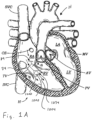
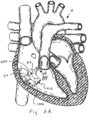
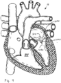
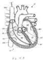
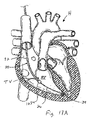
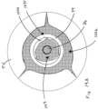
- FIGS 1A and 2A are cutaway views of the human heart H in diastolic and systolic phases, respectively.
- the right ventricle RV and left ventricle LV are separated from the right atrium RA and left atrium LA, respectively, by the tricuspid valve TV and mitral valve MV; i.e., the atrioventricular valves.
- the aortic valve AV separates the left ventricle LV from the ascending aorta (not identified) and the pulmonary valve PV separates the right ventricle from the pulmonary artery (also not identified).
- Each of these valves has flexible leaflets extending inward across the respective orifices that come together or "coapt" in the flowstream to form the one-way, fluid-occluding surfaces.
- the regurgitation reduction devices of the present application are described primarily with respect to the atrioventricular valves, and in particular the tricuspid valve. Therefore, anatomical structures of the right atrium RA and right ventricle RV will be explained in greater detail, though it should be understood that the devices described herein may equally be used to treat the mitral valve MV.
- the right atrium RA receives deoxygenated blood from the venous system through the superior vena cava SVC and the inferior vena cava IVC, the former entering the right atrium from above, and the latter from below.
- the coronary sinus CS is a collection of veins joined together to form a large vessel that collects deoxygenated blood from the heart muscle (myocardium), and delivers it to the right atrium RA.
- the venous blood that collects in the right atrium RA enters the tricuspid valve TV by expansion of the right ventricle RV.
- the right ventricle RV contracts to force the venous blood through the pulmonary valve PV and pulmonary artery into the lungs.
- the leaflets of the tricuspid valve TV close to prevent the venous blood from regurgitating back into the right atrium RA. It is during systole that regurgitation through the tricuspid valve TV becomes an issue, and then that the devices of the present application are most beneficial.
- a regurgitation reduction system includes a valved regurgitation reduction device 1034 and a device anchor 24.
- the valved regurgitation reduction device 1034 is placed in the tricuspid valve TV and held in place in the tricuspid valve TV by the anchor 24.
- the valved regurgitation reduction device 1034 can take a wide variety of forms.
- the illustrated valved regurgitation reduction device 1034 includes a valve 1000 (schematically illustrated check valve that can have any physical configuration) coupled to a coapting element 34.
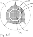
- FIG. 1A and 1B when the heart is in the diastolic phase, the valve 1000 opens and the tricuspid valve TV opens around the coapting element 34 of the valved regurgitation reduction device 1034. Blood flows from the right atrium RA to the right ventricle RV between the tricuspid valve TV and the coapting element 34 as indicated by arrows 1002 and/or through the valve 1000 as indicated by arrow 1004.
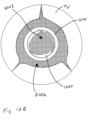
- Figure 1B illustrates space 1006 between the coapting element 34 and the tricuspid valve TV.
- the blank space 1008 in the coapting element 34 represents the valve 1000 being open when the heart is in the diastolic phase.
- the cross-hatching in Figure 1B illustrates areas through which blood flows. Cross-hatching similar to that shown in Figure 1B represents blood flow in other figures, unless otherwise indicated.
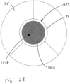
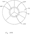
- FIG. 2A and 2B when the heart is in the systolic phase, the valve 1000 closes and the tricuspid valve TV closes around the coapting element 34 of the valved regurgitation reduction device 1034. Blood flow from the right ventricle RV to the right atrium RA is blocked by the tricuspid valve TV closing on the coapting element 34 and by the valve 1000 being closed and blocking blood flow as indicated by arrow 1010.
- Figure 2B illustrates the tricuspid valve sealing against the coapting element 34 and the tricuspid valve TV.
- the solid area 1012 in the coapting element 34 represents the valve 1000 being closed when the heart is in the systolic phase.
- the valved regurgitation reduction device 1034 can be adapted to reduce regurgitation of any heart valve.
- the valved regurgitation reduction device 1034 is placed in the mitral valve MV and held in place in the mitral valve MV by the anchor 24.
- the valve 1000 opens and the mitral valve MV opens around the coapting element 34 of the valved regurgitation reduction device 1034.
- valve 1000 closes and the mitral valve MV closes around the coapting element 34 of the valved regurgitation reduction device 1034. Blood flow from the left ventricle LV to the left atrium LA is blocked by the mitral valve MV closing on the coapting element 34 and by the valve 1000 being closed and blocking blood flow as indicated by arrow 1030.
- the valve 1000 of the valved regurgitation reduction device 1034 can take a wide variety of different forms.
- the valve 1000 can be configured to be installed transvascularly in the heart along with the coapting element 34.
- the valve 1000 and coapting element 34 may be expandable and collapsible to facilitate transvascular application in a heart.
- the valve 1000 may be configured for surgical application.
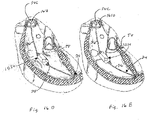
- Figures 5-11 illustrate a few of the many valve configurations that may be used. Any valve type may be used and some valves that are traditionally applied surgically may be modified for transvascular installation.
- Figure 5 illustrates an expandable valve for transvascular installation that is shown and described in US Patent No. 8,002,825 .
- FIG. 1 An example of a tri-leaflet valve is shown and described in Published Patent Cooperation Treaty Application No. WO 2000/42950 .
- An example of a tri-leaflet valve is shown and described in US Patent No. 5,928,281 .
- An example of a tri-leaflet valve is shown and described in US Patent No. 6,558,418 .
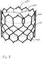
- Figures 6-8 illustrate an example of an expandable tri-leaflet valve.
- An example of an expandable tri-leaflet valve is the Edwards SAPIEN Transcatheter Heart Valve.
- the coapting element 34 may comprise a cage 900 of the expandable tri-leaflet valve with a covering 902 (see Figures 7 and 8 ).
- the covering 902 may cover the entire cage or a portion of it.
- the covering 902 may be configured to cover the portion of the cage 900 that is engaged by the tricuspid or mitral valve.
- the valve is a tri-leaflet valve compressed inside the cage 900.
- Figure 7 illustrates the cage 900 expanded and the valve 1000 in an open condition.
- Figure 8 illustrates the cage 900 expanded and the valve 1000 in a closed condition.
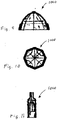
- Figures 9-11 illustrate an example of an expandable valve that is shown and described in US Patent No. 6,540,782 .
- a regurgitation reduction system can include a valved regurgitation reduction device 1034 and a device anchor 24.
- the valved regurgitation reduction device 1034 is placed in the tricuspid valve TV and held in place by the anchor 24.
- the valved regurgitation reduction device 1034 includes the valve 1000 of Figures 6-8 and the coapting element 34 comprises the cage 900, and cover 902 illustrated by Figures 6-8 .
- the cage 900 can take a wide variety of different forms.
- Figures 5-8 , 9-11 , 17B, and 17C illustrate a few of the possible cage configurations. However, any cage configuration capable of coapting with a native heart valve and supporting an artificial valve 1000 can be used.
- the cover 902 can take a wide variety of forms.
- the cover 902 can comprise one or more panels of bioprosthetic tissue sewn around portions of the frame 900.
- the cover 902 may be formed of a variety of xenograft sheet tissue, though bovine pericardial tissue is particularly preferred for its long history of use in cardiac implants, physical properties and relative availability. Other options are porcine or equine pericardium, for example.
- the cover 902 can be bioprosthetic tissue, such as bovine pericardium with a smooth side of the pericardium placed facing outward and a rough side facing inward. In the example illustrated by Figures 6-8 , the cover 902 has a proximal end that is open to fluid flow and a distal end that is also open.
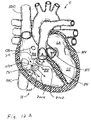
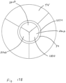
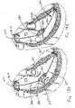
- FIG. 12A and 12B when the heart is in the diastolic phase, the valve 1000 opens and the tricuspid valve TV opens around the cage 900 and cover 902 of the valved regurgitation reduction device 1034. Blood flows from the right atrium RA to the right ventricle RV between the tricuspid valve TV and the cage 900 and cover 902 as indicated by arrows 2002 and/or through the valve 1000 as indicated by arrow 2004.
- Figure 12B illustrates space 2006 between the cage 900 and cover 902 and the tricuspid valve TV.
- the blank space 2008 represents the valve 1000 being open when the heart is in the diastolic phase.
- the cross-hatching in Figure 12B illustrates areas of blood flow.
- FIG. 13A and 13B when the heart is in the systolic phase, the valve 1000 closes and the tricuspid valve TV closes around the cage 900 and cover 902 of the valved regurgitation reduction device 1034. Blood flow from the right ventricle RV to the right atrium RA is blocked by the tricuspid valve TV closing on the cage 900 and cover 902, and by the valve 1000 being closed and blocking blood flow as indicated by arrow 2010.
- Figure 13B illustrates the tricuspid valve sealing against the cage 900 and cover 902.
- the tricuspid valve TV and the illustrated three cusps 2202 of the valve 1000 are shown as closed when the heart is in the systolic phase.
- a covering of pericardium or polymeric material may be provided over the cage to prevent abrasion of the leaflets against the cage. This covering can also serve to create a larger surface during coaptation.
- the valved regurgitation reduction device 1034 can be adapted to reduce regurgitation of any heart valve.
- the valved regurgitation reduction device 1034 is placed in the mitral valve MV where it is held in place by the anchor 24.
- the valve 1000 opens and the mitral valve MV opens around the cage 900 and cover 902 of the valved regurgitation reduction device 1034.
- valve 1000 closes and the mitral valve MV closes around the cage 900 and cover 902 of the valved regurgitation reduction device 1034. Blood flow from the left ventricle LV to the left atrium LA is blocked by the mitral valve MV closing on the cage 900 and cover 902 and by the valve 1000 being closed and blocking blood flow as indicated by arrow 2030.
- the anchor 24 can take a wide variety of different forms.
- the anchor can be introduced transvascularly or surgically.
- a few non-limiting examples of the many possible configurations for the anchor 24 are disclosed herein.
- Other anchor configurations may be implemented without departing from the scope of the present application.
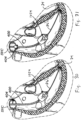
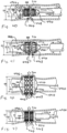
- Figures 15A and 15B are taken from Published Patent Cooperation Treaty Application No. WO 2013/173587 .
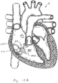
- Figures 15A and 15B show introduction of an anchoring catheter 20 into the right ventricle as a first step in deploying a valved regurgitation reduction device 1034 for reducing tricuspid valve regurgitation.
- the anchoring catheter 20 can enter the right atrium RA from the superior vena cava SVC after having been introduced to the subclavian vein (see Figure 20 ) using well-known methods, such as the Seldinger technique. Access for any of the devices disclosed herein may be femoral or subclavian.
- the anchoring catheter 20 preferably tracks over a pre-installed guide wire (not shown) that has been inserted into the subclavian vein and steered through the vasculature until it resides at the apex of the right ventricle.
- the physician advances the anchoring catheter 20 along the guide wire until its distal tip is touching at or near the ventricular apex, as seen in Figure 15A .
- Figure 15B shows retraction of a sheath 22 of the anchoring catheter 20 after installing a device anchor 24 at or near the apex of the right ventricle RV.
- the sheath 22 will generally be removed completely from the patient's body in favor of the anchoring catheter.
- the device anchor 24 is attached to an elongated anchor rail 26, which in some versions is constructed to have good capacity for torque.
- the anchor rail 26 may be constructed as a braided wire rod, or cable.
- the anchor 24 includes a plurality of circumferentially distributed and distally-directed sharp tines or barbs that pierce the tissue of the ventricular apex.
- the barbs 28 may be provided with an outward elastic bias so that they curl outward upon release from the sheath.
- the barbs are made of a super-elastic metal such as Nitinol.
- a super-elastic metal such as Nitinol.
- the device may be implanted with the assistance of a fluoroscope.
- a pigtail catheter may be placed in the right ventricle and contrast injected. This allows the user to see a clear outline of the annulus and the right ventricle.
- a frame of interest is selected (e.g., end systole) in which the annulus is clearly visible and the annulus to ventricular apex distance is minimized.
- the outline of the right ventricle, the annulus, and the pulmonary artery may be traced.
- the center of the annulus is then identified and a reference line placed 90° to it may be drawn extending to the right ventricular wall. This provides a clear linear target for anchoring.
- the anchor 24 is preferably located in the base of the ventricle between the septum and the free wall. Aligning the anchor rail 26 in this manner helps center the eventual positioning of a valved regurgitation reduction device 1034 of the system within the tricuspid leaflets.
- Figure 16A illustrates deployment of a valved regurgitation reduction device 1034 from a delivery catheter 32 that is disposed along the anchor rail 26.
- the valved regurgitation reduction device 1034 can be deployed from the delivery catheter 32 in the heart valve, such as the tricuspid valve TV or mitral valve.
- the deployed valved regurgitation reduction device 1034 can expand to the condition illustrated by Figures 16B and 16C or is expanded to the position illustrated by Figures 16B and 16C by an inflatable device.
- valved regurgitation reduction device 1034 fastens to a distal end of the delivery catheter 32, both of which slide along the anchor rail 26, which has been previously positioned as described above.
- the valved regurgitation reduction device 1034 resides within the tricuspid valve TV.
- Figure 16B illustrates the heart in the diastolic phase, with the leaflets of the tricuspid valve TV spaced apart from the valved regurgitation reduction device 1034.
- Figure 16C illustrates the heart in the systolic phase, with the leaflets closed in contact with the valved regurgitation reduction device 1034.
- the delivery catheter 32 optionally remains in the body as seen in Figure 20 , and the prefix "delivery” should not be considered to limit its function.
- a variety of valved regurgitation reduction devices 1034 are described herein, the common feature of which is providing a valved-plug of sorts within the heart valve leaflets to both mitigate or otherwise eliminate regurgitation in the systolic phase and enhance blood flow in the diastolic phase.
- valved regurgitation reduction device 1034 may be mounted to the anchor rail 26 and/or catheter 32 in a wide variety of different ways.
- the valved regurgitation reduction device 1034 may be mounted to the anchor rail with a strut structure where the anchor rail passes through the valved regurgitation reduction device 1034 (See Figures 18B and 18C ), by external wires where the anchor rail 26 does not pass through the valved regurgitation reduction device 1034 (See Figures 30A and 30B), and/or an outside surface of the valved regurgitation reduction device 1034 may be mounted to the anchor rail 26 and/or catheter 32 (See Figure 23 ).
- a locking mechanism can be coupled to the valved regurgitation reduction device 1034 to lock its position within the tricuspid valve TV and relative to the fixed anchor rail 26.
- a locking collet 40 along the length of the delivery catheter 32 permits the physician to selectively lock the position of the delivery catheter, and thus the connected valved regurgitation reduction device 1034, on the anchor rail 26.
- a crimpable section such as a stainless steel tube may be included on the delivery catheter 32 at a location near the skin entry point and spaced apart from the location of the coapting element 34.
- the physician need only position the coapting element 34 within the leaflets, crimp the catheter 32 onto the anchor rail 26, and then sever both the catheter and rail above the crimp point.
- the delivery catheter 32 is left in place after placement of the valved regurgitation reduction device 1034. Alternatively, the delivery catheter is removed, leaving only the anchor 24 and the valved regurgitation reduction device 1034.
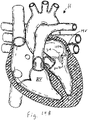
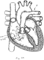
- an entire regurgitation reduction system 30 can be seen extending from near the apex of the right ventricle RV upward through the superior vena cava SVC and into the subclavian vein SV.
- a proximal length of the delivery catheter 32 including the locking collet 40 exits the subclavian vein SV through a puncture and remains implanted subcutaneously; preferably coiling upon itself as shown.
- the physician first ensures proper positioning of the valved regurgitation reduction device 1034 within the tricuspid valve TV, then locks the delivery catheter 32 with respect to the anchor rail 26 by actuating the locking collet 40, and then severs that portion of the delivery catheter 32 that extends proximally from the locking collet.
- the collet 40 and/or coiled portion of the delivery catheter 32 may be sutured or otherwise anchored in place to subcutaneous tissues outside the subclavian vein SV. It is also worth noting that since the delivery catheter 32 slides with respect to the anchor rail 26, it may be completely removed to withdraw the valved regurgitation reduction device 1034 and abort the procedure - either during or after implantation.
- the implant configuration is similar to that practiced when securing a pacemaker with an electrode in the right atrium muscle tissue with the leads extending to the associated pulse generator placed outside the subclavian vein. Indeed, the procedure may be performed in conjunction with the implant of a pacing lead.
- Figures 16D and 16E illustrate an example where the delivery catheter is removed, leaving only the anchor 24 and the valved regurgitation reduction device 1034.
- Figure 16D illustrates the heart in the diastolic phase, with the leaflets of the tricuspid valve TV spaced apart from the valved regurgitation reduction device 1034.
- Figure 16E illustrates the heart in the systolic phase, with the leaflets closed in contact with the valved regurgitation reduction device 1034.
- the rail 26 is connected to a stent 1610 disposed in the superior vena cava SVC to set the position of the valved regurgitation reduction device 1034, with the catheter removed.
- the anchor can take a wide variety of different forms.
- a multi-strut frame 184 includes a collar 188 that slideably couples and is optionally securable to the rail 26.
- the collar 188 has a plurality of, preferably three, struts 190 that angle outward from it in a proximal or atrial direction and terminate in small pads or feet 192.
- the feet 192 attach to a distal end of the valved regurgitation reduction device 1034.
- the struts 190 may be resilient such that the feet 192 apply radial outward forces to the valved regurgitation reduction device 1034 so as to maintain the distal end of the valved regurgitation reduction device 1034 open.
- a three- strut mechanical frame 152 is retained by a pair of end collars 162 that are optionally secured to a delivery catheter 32 and/or slideably coupled and optionally securable to the rail 26.
- the frame 152 is compressible and expands in its relaxed configuration.
- Figure 17C illustrates an inner strut frame 50 that includes a short tubular collar 54 that optionally fastens to the distal end of the delivery catheter 32 and/or which slideably couples and is optionally securable to the rail 26.
- a second tubular collar 58 holds together the distal ends of the struts 56 and attaches to a small ferrule 60 having a through bore that slides over the anchor rail 26.
- the second collar 58 and/or the small ferrule 60 slideably couple and are optionally securable to the rail 26.
- Each of the struts 56 has proximal and distal ends that are formed as a part of (or constrained within) these collars 54, 58 and a mid-portion that arcs radially outward to extend substantially parallel to the axis of the valved regurgitation reduction device 1034.
- the frame shape is thus a generally elongated oval. In the illustrated example, there are six struts 56 in the frame 50, although more or less could be provided.
- the struts 56 are desirably formed of a super-elastic material such as Nitinol so as to have a minimum amount of rigidity to form the generally cylindrical outline of the frame but maximum flexibility so that the frame deforms from the inward forces imparted by the heart valve leaflets.
- valved regurgitation reduction devices 1034 are described in the present application. Indeed, the present application provides a plurality of solutions for preventing regurgitation in atrioventricular valves, none of which should be viewed as necessarily more effective than another.
- the choice of valved regurgitation reduction device 1034 may depend partly on physician preference, partly on anatomical particularities, partly on the results of clinical examination of the condition of the patient, and other factors.
- the valved regurgitation reduction device 1034 can comprise a valve 1000 made at least partially from bioprosthetic tissue disposed within an expandable and contractible frame 900 that is at least partially covered 902 with bioprosthetic tissue.
- the frame 900 may be rigid after being expanded from the condition illustrated by Figure 6 to the condition illustrated by Figure 7 .
- the bioprosthetic tissue covering 902 helps reduce material interactions between the native leaflets and the inner mechanical frame.
- the regurgitation reduction device 1034 can be effectively deployed at either the tricuspid or the mitral valve.
- the former typically has three leaflet cusps defined around the orifice, the latter just two.
- the tissue-covered mechanical frame structure thus represents an effective co-optation element for both valves.
- FIG 18A illustrates deployment of a valved regurgitation reduction device 1034 from a delivery catheter 32 that is disposed along the anchor rail 26.
- the valved regurgitation reduction device 1034 can be deployed from the delivery catheter 32 in the heart valve, such as the tricuspid valve TV or mitral valve MV.
- the deployed valved regurgitation reduction device 1034 expands to the condition illustrated by Figures 18B and 18C or is expanded to the position illustrated by Figures 18B and 18C by an inflatable device.
- valved regurgitation reduction device 1034 illustrated by Figures 6-8 has a distal end mounted to the frame 184 illustrated by Figure 17A to slideably couple it to the rail 26.
- valved regurgitation reduction device 1034 illustrated by Figures 6-8 has both ends mounted to a frame 184 illustrated by Figure 17A to slideably couple it to the rail 26.
- FIGS 18A-18C illustrate deployment of a delivery catheter 32 advanced along the anchor rail 26 to position the valved regurgitation reduction device 1034 within the tricuspid valve TV.
- the valved regurgitation reduction device 1034 optionally fastens to a distal end of the delivery catheter 32, both of which slide along the anchor rail 26, which has been previously positioned as described above.
- the valved regurgitation reduction device 1034 resides within the tricuspid valve TV.
- Figure 18B illustrates the heart in the diastolic phase, with the leaflets of the tricuspid valve TV spaced apart from the valved regurgitation reduction device 1034.
- Figure 18C illustrates the heart in the systolic phase, with the leaflets closed in contact with the valved regurgitation reduction device 1034.
- the delivery catheter 32 optionally remains in the body as seen in Figure 20 .
- the frame 184 is connectable to the rail 26, the proximal end of the rail is connectable to another structure in the heart or body, and the delivery catheter 32 is removed from the body. This leaves only the valved regurgitation reduction device 1034 and an anchor 24.
- a locking mechanism is provided to lock the valved regurgitation reduction device 1034 in its position within the tricuspid valve TV and relative to the fixed anchor rail 26.
- a locking collet 40 along the length of the delivery catheter 32 and/or providing the frame 184 with a mechanism that is selectively lockable to the rail 26 permits the physician to selectively lock the position of the delivery catheter and/or the connected valved regurgitation reduction device 1034, on the anchor rail 26.
- Figures 18D and 18E illustrate an example, where the delivery catheter 32 of Figures 18A-18C is removed, leaving only the anchor 24 and the valved regurgitation reduction device 1034.
- Figure 18D illustrates the heart in the diastolic phase, with the leaflets of the tricuspid valve TV spaced apart from the valved regurgitation reduction device 1034.
- Figure 18E illustrates the heart in the systolic phase, with the leaflets closed in contact with the valved regurgitation reduction device 1034.
- the rail 26 is connected to a stent 1610 disposed in the superior vena cava SVC to set the position of the valved regurgitation reduction device 1034, with the catheter removed.
- the anchor 24 can take a wide variety of different forms.
- Figure 19A illustrates that when the heart is in the diastolic phase, the valve 1000 opens and the tricuspid valve TV opens around the cage 900 and cover 902 of the valved regurgitation reduction device 1034.
- the rail 26 is disposed inside the open valve 1000. Blood flows from the right atrium RA to the right ventricle RV between the tricuspid valve TV and the cage 900 and cover 902 as and through the valve 1000 around the rail 26.
- the valve 1000 closes around the rail 26 and the tricuspid valve TV closes around the cage 900 and cover 902 of the valved regurgitation reduction device 1034.
- the leaflets or cusps of the valve 1000 seal against one another and against the rail 26.
- the rail 26 or the portion of the rail that engages the valve 1000 can be covered, coated, or made from a material that is compatible with the valve.
- the rail 26 or the portion of the rail that engages the valve 1000 may be covered, coated, or made from the same material as the leaflets of the valve. Blood flow from the right ventricle RV to the right atrium RA is blocked by the tricuspid valve TV closing on the cage 900 and cover 902 and by the valve 1000 being closed against the rail 26.
- valved regurgitation reduction device 1034 illustrated by Figures 6-8 is mounted to wires 3000 that are part of the rail 26 and/or are disposed inside the delivery catheter 32.
- the wires 3000, rail 26, and /or delivery catheter 32 are adjustable to adjust the position and orientation of the valved regurgitation reduction device 1034 with respect to the tricuspid valve TV (or mitral valve MV).
- extending or retracting one or more, but less than all of the wires 3000 pivots the valved regurgitation reduction device 1034 to allow for axial alignment of the valved regurgitation reduction device 1034 with respect to the tricuspid valve TV (or mitral valve MV).
- FIG 22A illustrates that when the heart is in the diastolic phase, the valve 1000 opens and the tricuspid valve TV opens around the cage 900 and cover 902 of the valved regurgitation reduction device 1034.
- No rail 26 is disposed inside the open valve 1000.
- the valve 1000 closes and the tricuspid valve TV closes around the cage 900 and cover 902 of the valved regurgitation reduction device 1034.
- the leaflets or cusps of the valve 1000 seal against one another. Blood flow from the right ventricle RV to the right atrium RA is blocked by the tricuspid valve TV closing on the cage 900 and cover 902 and by the valve 1000 being closed.
- an external surface of the valved regurgitation reduction device 1034 illustrated by Figures 6-8 is attached to the rail 26 and/or the catheter 32.
- the valved regurgitation reduction device 1034 can be connected to a distal end of the catheter 32 and/or an outside surface of the valved regurgitation reduction device 1034 can include a connection 3202 that is slideable on the rail 26 until the valved regurgitation reduction device 1034 is positioned in the tricuspid valve TV (or mitral valve MV) and is then secured to the rail 26 to set the position of the valved regurgitation reduction device 1034 relative to the tricuspid valve TV (or mitral valve MV)
- the valve 1000 and tricuspid valve TV (or mitral valve MV) in the arrangement illustrated by Figure 23 open and close in the same manner as in the arrangement illustrated by Figure 21 (See Figures 22A and 22B ).
- Figures 24A-24C , 25A , and 25B illustrate an example where the valve 1000 of the valved regurgitation reduction device 1034 includes a sealing element 3302 and an outer skirt or ring 3304.
- the sealing element 3302 includes a substantially stationary center portion 3306 and radially outer portion 3308.
- the radially outer portion 3308 moves inward (see arrow 3305 in Figure 25A ) to open and radially outward to close (see arrow 3307 in Figure 25B ).
- the radially outer portion 3308 seals against the outer skirt or ring 3304.
- the valve 1000 illustrated by Figures 24A-24C , 25A and 25B is expandable so that it can be installed transvascularly.
- the valve 1000 illustrated by Figures 24A , 24B , 25A and 25B is constructed substantially as shown and described in US Patent No. 6,540,782 .
- Figure 24A illustrates deployment of a valved regurgitation reduction device 1034 from a delivery catheter 32 that is disposed along the anchor rail 26.
- the valved regurgitation reduction device 1034 can be deployed from the delivery catheter 32 in the heart valve, such as the tricuspid valve TV or mitral valve MV.
- the deployed valved regurgitation reduction device 1034 expands to the condition illustrated by Figures 24B and 24C or is expanded to the position illustrated by Figures 24B and 24C by an inflatable device.
- the rail 26 extends through center portion 3306 of the valve 1000 of the valved regurgitation reduction device 1034 to slideably couple the valved regurgitation reduction device 1034 to the rail 26.
- Figures 24A-24C illustrate deployment of a delivery catheter 32 advanced along the anchor rail 26 to position the valved regurgitation reduction device 1034 within the tricuspid valve TV.
- the center portion 3308 of the valved regurgitation reduction device 1034 optionally fastens to a distal end of the delivery catheter 32, both of which slide along the anchor rail 26, which has been positioned.
- the valved regurgitation reduction device 1034 resides within the tricuspid valve TV.
- Figure 24B illustrates the heart in the diastolic phase, with the leaflets of the tricuspid valve TV spaced apart from the valved regurgitation reduction device 1034.
- Figure 24C illustrates the heart in the systolic phase, with the leaflets closed in contact with the valved regurgitation reduction device 1034.
- the delivery catheter 32 optionally remains in the body as seen in Figure 20 .
- the center portion 3308 of the valve 1000 is connectable to the rail 26, the proximal end of the rail is connectable to another structure in the heart or body, and the delivery catheter 32 is removed from the body. This leaves only the valved regurgitation reduction device 1034 and an anchor 24.
- a locking mechanism is provided on the valved regurgitation reduction device 1034 to lock its position within the tricuspid valve TV and relative to the fixed anchor rail 26.
- a locking collet 40 along the length of the delivery catheter 32 and/or providing the center portion 3306 of the valve 1000 with a mechanism that is selectively lockable to the rail 26 permits the physician to selectively lock the position of the delivery catheter and/or the connected valved regurgitation reduction device 1034, on the anchor rail 26.
- Figure 25A illustrates that when the heart is in the diastolic phase, the valve 1000 opens and the tricuspid valve TV opens around the valved regurgitation reduction device 1034.
- the radially outer portion 3308 moves inward 3305 away from the outer skirt 3304 to open.
- the blood flows through gaps 3320 between the outer skirt 3304 and the sealing element 3302.
- the rail 26 is disposed inside the open valve 1000, but not in the gaps 3320. Blood flows from the right atrium RA to the right ventricle RV between the tricuspid valve TV and the valved regurgitation reduction device 1034 and through the valve 1000 around the rail 26.
- valve 1000 closes by movement (indicated by arrows 33307) of the valve element 3302 into contact with the skirt 3304 and the tricuspid valve TV closes around the valved regurgitation reduction device 1034.
- movement indicated by arrows 33307
- the tricuspid valve TV closes around the valved regurgitation reduction device 1034.
- the anchor 24 can take a wide variety of different forms. The following description provides non-limiting examples of catheter, railing, and anchoring systems.
- an anchoring catheter 360 is directed to or near the apex of the right ventricle using an L-shaped stabilizing catheter 362 secured within a coronary sinus.
- the catheter 362 is capable of deflecting into an L-shape, and would be advanced from the SVC, into the right atrium, then into the coronary sinus, which would provide a stabilizing feature for the guide catheter.
- the catheter 362 could be maneuvered further in or out of the coronary sinus such that the "elbow" of the L-shape is positioned directly above the center of the valve, then the anchor catheter 360 could be delivered through the lumen of the guide catheter 362 and out a port at the elbow of the L-shape.
- a temporary stiffening "stylet" (not shown) could be used through the anchor rail lumen to ensure the anchor is delivered directly downwards to the ideal point at the RV apex.
- the coapting element could instead be anchored directly to the annulus or a ring 4700 that is connected to the annulus (see Figures 38-43 ).
- a series of at least two anchors 370 could be deployed into the fibrous portion of the annulus, then cables or stabilizing rods 372 could be used to hang or suspend the valved regurgitation reduction device 1034 within the annulus plane.
- the ring 4700 illustrated by Figures 38-43 could be used to hang or suspend the valved regurgitation reduction device 1034 in the same or a similar way.
- Each support cable or rod 372 would need to be relatively taut, so as to prevent motion of the device towards the atrium during systole. Any number of support struts could be utilized.
- the support cables for suspending the valved regurgitation reduction device 1034 from the annulus could be relatively flexible, and thus the position and mobility of the device would be altered via tension in the cables.
- the support elements could be relatively stiff to decrease device motion, but this would require changing anchor position to reposition the coapting element.
- an anchor 376 to the RV apex is shown, the dual annulus anchors 370 might obviate the need for a ventricular anchor.
- FIG 28 illustrates an example where an adjustable stabilizing rod 380 is mounted on a delivery catheter 382 and secured to an anchor 384 within the coronary sinus.
- the stabilizing rod 380 attaches via an adjustable sleeve 386 to the catheter 382, thus suspending the attached valved regurgitation reduction device 1034 down into the tricuspid valve TV.
- a sliding mechanism on the adjustable sleeve 386 permits adjustment of the length between the coronary sinus anchor 384 and the valved regurgitation reduction device 1034, thus allowing positioning of the coapting element at the ideal location within the valve plane.
- this coronary sinus anchoring concept could also be coupled with a traditional anchor in the RV apex, as shown.
- Figure 29 illustrates an alternative delivery catheter 390 having a pivot joint 392 just above the valved regurgitation reduction device 1034 for angle adjustment. If a given combination of SVC access angle and/or RV anchor position resulted in a crooked valved regurgitation reduction device 1034 within the valve plane, the catheter 390 could be articulated using the pull wire (not shown) until proper alignment is achieved based on feedback from fluoroscopic views.
- Additional flex points could be added to further facilitate control of device angle, e.g. another flex point could be added distal to the valved regurgitation reduction device 1034 to compensate for the possible case that the RV wall angle (and thus the anchor angle) is skewed with respect to the valve plane. This would require an additional independent lumen within the catheter body 390 to facilitate translation of another pull wire to operate the second flex feature.
- a single flex point proximal to the valved regurgitation reduction device 1034 were determined to be sufficient for orienting the device, and if the catheter were rigid enough to resist the forces of systolic flow, the section 396 of the device distal to the coapting element could be removed all together.
- the catheter could contain a shape-set shaft comprised of Nitinol or another shape memory material, which would be released from a rigid delivery sheath into its "shaped" form in order to optimize device angle from the SVC. It could be possible to have a few catheter options of varying pre-set angles, yet choose only one after evaluation of the SVC-to-valve plane angle via angiographic images.
- FIGS. 30 and 31 show two ways to anchor the delivery catheter 400 to the superior vena cava SVC for stabilizing a valved regurgitation reduction device 1034.
- a variety of hooks or anchors 404 could extend from a second lumen within the catheter 402 with the ability to grab onto the SVC wall and pull the catheter in that direction.
- a stiffer element could extend outwards perpendicular to the catheter axis to butt up against the SVC wall and push the catheter in the opposite direction.
- such a mechanism could potentially be useful for achieving better coaxial alignment with the valve.
- Figures 32 and 33 show an example with pull wires 412 extending through the delivery catheter 414 for altering the position of the valved regurgitation reduction device 1034 within the tricuspid valve leaflets. If the valved regurgitation reduction device 1034 is located out of the middle of the valve leaflets such that it does not effectively plug any regurgitant jets, which can be seen on echocardiography, then one of the pull wires 412 can be shortened or lengthened in conjunction with rotating the catheter 414 to reposition the valved regurgitation reduction device 1034.
- pacemaker leads are frequently anchored in the right ventricle with chronic success
- the anchor for the present device would see significantly higher cyclic loads due to systolic pressure acting on the valved regurgitation reduction device 1034.
- anchoring a device in the ventricle may not be ideal.
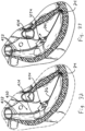
- An alternative anchoring approach could take advantage of the fairy collinear orientation of the superior and inferior vena cava, wherein, as seen in Figure 34 , two stent structures 420, 422 would effectively "straddle" the tricuspid valve by expanding one in the superior vena cava and the other in the inferior vena cava.
- valved regurgitation reduction device 1034 would then hang down through the tricuspid valve plane from an atrial shaft 426 attached to a connecting wire or rod 428 between the two caval stents 420, 422.
- the shaft 426 from which the coapting element 424 hangs would be fairly rigid under compressive and bending stresses.
- the valved regurgitation reduction device 1034 would desirably be positioned within the tricuspid valve TV using a sliding mechanism along the connecting rod 428 between the two caval stents.
- the coaxial orientation of the SVC and IVC could also be leveraged for delivering an anchor into the RV.
- a delivery catheter could be passed through the SVC into the IVC, and a "port" or hole off the side of the delivery catheter could be aligned with the center of the valve.
- the anchor could be passed through the lumen of the delivery system and out the port, resulting in a direct shot through the center of the annulus and to the RV wall in the ideal central anchor location.
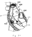
- a valved regurgitation reduction device 1034 could reside between the mitral valve leaflets with anchors on both the proximal and distal ends: one attaching to the septal wall, and the other anchoring in the left atrial appendage.
- the septal anchor could be a helical or hook-style anchor
- the left atrial appendage anchor could be an expandable metallic structure with a plurality of struts or wireforms designed to oppose against the appendage wall and provide stability to the coapting element.
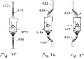
- Figures 35-37 are schematic views of a valved regurgitation reduction device 1034 mounted for lateral movement on a flexible delivery catheter 432 that features controlled buckling. It is challenging to reposition the valved regurgitation reduction device 1034 from an off-center location to the ideal central location within the valve plane, given a fixed angle from the SVC and a fixed anchor position in the RV.
- the device catheter 432 could be comprised of a fairly stiff shaft except for two relatively flexible regions 434, 436 directly proximal and distal to the coapting element section.
- the farthest distal section of the valved regurgitation reduction device 1034 could be locked down relative to the anchor rail over which it slides, and then the catheter 432 could be advanced distally thus compressing it and causing the two flexible sections 434, 436 to buckle outwards and displace the valved regurgitation reduction device 1034 laterally with respect to the catheter axis (see Figure 36 ).
- the user could employ a combination of sliding and rotating of the catheter to reposition the valved regurgitation reduction device 1034 within the valve. Instead of locking the distal end of the catheter onto an anchor rail before adjustment, if the catheter were comprised of multiple lumens, the outer lumen could slide distally relative to the inner lumen, thus producing the same buckling effect.
- Figures 38-43 illustrate an embodiment where the size of the valve annulus 300 is contracted or reduced in size as indicated by arrows 4701 before introduction of a valved regurgitation reduction device 1034 (or a coapting element disclosed by Published Patent Cooperation Treaty Application No. WO 2013/173587 ).
- a valved regurgitation reduction device 1034 or a coapting element disclosed by Published Patent Cooperation Treaty Application No. WO 2013/173587 .
- the size of the valve annulus 300 can be contracted or reduced in a wide variety of different ways.
- Figures 38-43 illustrate the use of a ring or stent 4700 to reduce or contract the valve annulus, but other devices and methods could be employed.
- valved regurgitation reduction device 1034 or combination of the valved regurgitation reduction devices 1034 described herein and/or coapting elements disclosed by Published Patent Cooperation Treaty Application No. WO 2013/173587 can be used in a valve annulus that has been contracted or reduced in size by a ring, stent, or other device or method.
- the ring or stent 4700 can take a wide variety of different forms.
- Figures 40-43 are modified versions of figures from US Patent No. 8,870,949 to Rowe.
- a device or devices disclosed by US Patent No. 8,870,949 is used or is modified to be used to contract or reduce the size of a heart valve, such as the tricuspid valve TV or the mitral valve MV.
- Figures 40-43 illustrate delivery of a ring or stent 4700.
- the stent or ring 4700 is introduced and positioned across the valve annulus 300 by being inserted at least partially through native valve leaflets 302 and expanded.
- the valved regurgitation reduction devices 1034 disclosed in this application and the coapting devices disclosed by Published Patent Cooperation Treaty Application No. WO 2013/173587 act in conjunction with the native valve leaflets 302, instead of completely replacing the functionality of the native valve leaflets 302.
- the ring or stent 4700 is positioned such that a distal end 4906 is at a position 4908 that is before the annulus 300 (see also Figure 38 ) or is positioned such that a proximal end 4910 is at a position 4912 that is after the annulus.
- two separate rings or stents 4700 are used, with one ring or stent at a position 4908 that is before the annulus 300 and one ring or stent 4700 positioned at a position 4912 that is after the annulus.
- the ring or stent 4700 may be introduced into the patient's body using a percutaneous delivery technique with the balloon portion 4902 of the balloon catheter 4900 deflated, and the ring or stent 4700 operably disposed thereon.
- the ring or stent 4700 can be contained in a radially crimped or compressed state.
- the stent or ring 4700 can be held in a compressed state for delivery, by, for example, containing the stent or ring 4700 within an outer covering or sheath 4701.
- the outer covering 4701 can be removed or retracted, or the stent or ring 4700 pushed through the outer covering 4701, to allow the self-expandable stent or ring 4700 to self-expand.
- an outer covering may not be needed to retain the ring or stent 4700 in a crimped state, but can nonetheless be used if desired (e.g. to reduce friction during delivery).
- the stent or ring 4700 includes projections 4710 of a grabbing mechanisms 4708 are disposed around the outside circumference stent or ring 4700.
- the stent or ring 4700 is introduced and positioned with respect to the valve annulus 300 and expanded.
- a diameter D1 of the regurgitant valve 300, 302 is larger than the diameter of a healthy valve in Figures 40-43 .
- outer sheath or covering 4701 can be retracted or removed from over the stent or ring 4700.
- the stent or ring 4700 can expand from its crimped or compressed diameter d to a predetermined or memorized diameter R once the sheath 201 is removed.
- the balloon portion 4902 of the balloon catheter 4900 is expanded to increase the diameter of the stent or ring 4700 from its relaxed diameter R ( Figure 41 ) to an over-expanded diameter OE such that the outer diameter of the stent or ring 4700 equals or exceeds the original diameter D1 of the annulus 300.
- the annulus 300 may expand beyond the diameter D1 as well.
- the projections 4710 of the grabbing mechanisms 4708 are forced to contact and can penetrate or otherwise engage (e.g. clamp or grab) the target tissue, which may include tissue on one or both sides of the annulus 300. This causes the stent or ring 4700 to adhere to the tissue on one or both sides of the annulus 300.
- the balloon portion 4902 of the balloon catheter 4900 can be deflated, and the balloon catheter 4900 removed.
- the stent or ring 4700 is formed of a shape memory material
- removing the expansion force of balloon 4902 from the stent or ring 4700 allows the stent or ring 4700 to return from an over-expanded diameter OE ( Figure 42 ) to a recoil or relaxed diameter R or some diameter between the over-expanded diameter OE and the recoil or relaxed diameter R.
- the diameter that the ring or stent 4700 returns to is closer to the relaxed diameter R than the over-expanded diameter OE.
- the manufacture of the ring or stent 4700 determines what the recoil diameter will be.
- the recoil diameter of a support structure comprising a shape memory alloy can be the memorized or functional diameter of the support structure.
- the recoil diameter of a support structure comprising, for example, stainless steel and/or cobalt chromium can be that of the natural or resting diameter of the support structure, once it inherently recoils from being over-expanded by the balloon 4902.
- the diameter of ring or stent 4700 decreases to the recoil diameter R
- the diameter of the annulus 300 also decreases to a final diameter D2.
- the annulus 300 decreases in diameter due to the projections 4710 of the ring or stent 4700 pulling the target tissue inward.
- the ring or stent 4700 is installed at the same time or a different time than the valved coapting device 1034.
- the ring or stent 4700 can be installed in the patient three to six months prior to installation of the valved coapting device 1034 or a prosthetic replacement valve (TTVR). This time allows tissue to grow into the ring or stent to form a stable or solid prosthetic annulus.
- the ring or stent 4700 may be coated to promote tissue growth.
- the ring or stent 4700 may be coated with a polymer, such as Dacron, etc. to promote tissue growth.
- WO 2013/173587 may be installed in the prosthetic orifice at the same time as the ring 4700. If regurgitation of the valve continues or worsens over time, the valved coapting device 1034 or a coapting device disclosed by Published Patent Cooperation Treaty Application No. WO 2013/173587 can be easily removed and the ring or stent 4700 provides a solid prosthetic seat for a prosthetic valve that replaces the regurgitant valve, instead of working with the regurgitant valve.
Claims (6)
- Système de réduction de régurgitation valvulaire destiné à une valvule cardiaque native ayant des feuillets natifs et un anneau, système de réduction de régurgitation valvulaire comprenant :une bague (4700) configurée pour réduire une taille de l'anneau ;un dispositif de réduction de régurgitation valvulaire (1034) qui comporte :un élément de coaptation (34) configuré pour agir en conjonction avec les feuillets natifs (302) ;une valvule (1000) couplé à l'élément de coaptation (34)un ancrage (24) configuré pour positionner le dispositif de réduction de regurgitation valvulaire (1034) entre les feuillets d'une valvule cardiaque native ;dans lequel l'élément de coaptation (34) est configuré par rapport à la valvule cardiaque native avec la taille d'anneau réduite pour former un espace entre les feuillets de la valvule cardiaque native et l'élément de coaptation (34) lorsque le coeur est dans une phase diastolique et de telle sorte que les feuillets de la valvule cardiaque native se scellent contre l'élément de coaptation (34) lorsque le coeur est dans la phase systolique ; etdans lequel la valvule (1000) couplée à l'élément de coaptation (34) est configurée pour s'ouvrir et permettre un écoulement à travers l'élément de coaptation (34) lorsque le coeur est dans une phase diastolique et pour se fermer et empêcher un écoulement à travers l'élément de coaptation (34) lorsque le coeur est dans la phase systolique.
- Système de réduction de régurgitation valvulaire selon la revendication 1, dans lequel l'élément de coaptation (34) est configuré pour former un espace entre une valvule tricuspide native et l'élément de coaptation (34) lorsque le coeur est dans une phase diastolique et de telle sorte que les feuillets de la valvule tricuspide native se scellent contre l'élément de coaptation (34) lorsque le coeur est dans la phase systolique.
- Système de réduction de régurgitation valvulaire selon la revendication 1, dans lequel l'élément de coaptation (34) est configuré pour former un espace entre une valvule mitrale native et l'élément de coaptation (34) lorsque le coeur est dans une phase diastolique et de telle sorte que les feuillets de la valvule mitrale native se scellent contre l'élément de coaptation (34) lorsque le coeur est dans la phase systolique.
- Système de réduction de régurgitation valvulaire selon la revendication 1, dans lequel l'élément de coaptation (34) et la valvule (1000) couplée à l'élément de coaptation (34) sont extensibles pour permettre au dispositif de réduction de régurgitation valvulaire (1034) d'être déployé par voie transvasculaire.
- Système de réduction de régurgitation valvulaire selon la revendication 1, dans lequel la valvule (1000) couplée à l'élément de coaptation (34) est une valvule de type à trois feuillets.
- Système de réduction de régurgitation valvulaire selon la revendication 1, dans lequel la valvule (1000) couplée à l'élément de coaptation (34) est disposé dans l'élément de coaptation (34).
Applications Claiming Priority (4)
| Application Number | Priority Date | Filing Date | Title |
|---|---|---|---|
| US201562249815P | 2015-11-02 | 2015-11-02 | |
| US201562273313P | 2015-12-30 | 2015-12-30 | |
| US201662291406P | 2016-02-04 | 2016-02-04 | |
| PCT/US2016/060035 WO2017079234A1 (fr) | 2015-11-02 | 2016-11-02 | Dispositifs et procédés de réduction de régurgitation valvulaire cardiaque |
Publications (3)
| Publication Number | Publication Date |
|---|---|
| EP3370649A1 EP3370649A1 (fr) | 2018-09-12 |
| EP3370649A4 EP3370649A4 (fr) | 2018-12-26 |
| EP3370649B1 true EP3370649B1 (fr) | 2023-03-15 |
Family
ID=58662661
Family Applications (1)
| Application Number | Title | Priority Date | Filing Date |
|---|---|---|---|
| EP16862838.6A Active EP3370649B1 (fr) | 2015-11-02 | 2016-11-02 | Dispositifs de réduction de régurgitation valvulaire cardiaque |
Country Status (3)
| Country | Link |
|---|---|
| US (1) | US20170143478A1 (fr) |
| EP (1) | EP3370649B1 (fr) |
| WO (1) | WO2017079234A1 (fr) |
Families Citing this family (49)
| Publication number | Priority date | Publication date | Assignee | Title |
|---|---|---|---|---|
| US8172856B2 (en) | 2002-08-02 | 2012-05-08 | Cedars-Sinai Medical Center | Methods and apparatus for atrioventricular valve repair |
| US9345573B2 (en) | 2012-05-30 | 2016-05-24 | Neovasc Tiara Inc. | Methods and apparatus for loading a prosthesis onto a delivery system |
| US10080657B2 (en) | 2013-03-07 | 2018-09-25 | Cedars-Sinai Medical Center | Catheter based apical approach heart prostheses delivery system |
| US10105221B2 (en) | 2013-03-07 | 2018-10-23 | Cedars-Sinai Medical Center | Method and apparatus for percutaneous delivery and deployment of a cardiovascular prosthesis |
| WO2016040526A1 (fr) | 2014-09-10 | 2016-03-17 | Cedars-Sinai Medical Center | Procédé et appareil de mise en place percutanée et de déploiement d'une prothèse valvulaire cardiaque |
| WO2016050751A1 (fr) | 2014-09-29 | 2016-04-07 | Martin Quinn | Dispositif et procédé de traitement de valvule cardiaque |
| US10758265B2 (en) | 2014-11-14 | 2020-09-01 | Cedars-Sinai Medical Center | Cardiovascular access and device delivery system |
| JP7068161B2 (ja) | 2015-07-23 | 2022-05-16 | セダーズ-シナイ メディカル センター | 心臓弁尖を固定するためのデバイス |
| USD856517S1 (en) | 2016-06-03 | 2019-08-13 | Musculoskeletal Transplant Foundation | Asymmetric tissue graft |
| WO2018140535A1 (fr) | 2017-01-25 | 2018-08-02 | Cedars-Sinai Medical Center | Dispositif pour la fixation de feuillets valvulaires cardiaques |
| US10869758B2 (en) * | 2017-02-06 | 2020-12-22 | Caisson Interventional Llc | Systems and methods for heart valve therapy |
| US10932909B2 (en) * | 2017-02-07 | 2021-03-02 | Shanghai Joy Medical Devices Co., Ltd | Device for treating regurgitation of tricuspid and implantation method therefor |
| US11337685B2 (en) | 2017-04-05 | 2022-05-24 | Opus Medical Therapies, LLC | Transcatheter anchoring assembly for a mitral valve, a mitral valve, and related methods |
| US10820992B2 (en) | 2017-04-05 | 2020-11-03 | Opus Medical Therapies, LLC | Transcatheter atrial sealing skirt, anchor, and tether and methods of implantation |
| US11103351B2 (en) | 2017-04-05 | 2021-08-31 | Opus Medical Therapies, LLC | Transcatheter atrial sealing skirt and related method |
| EP3606444B1 (fr) | 2017-04-05 | 2023-09-13 | Opus Medical Therapies, LLC | Jupe d'étanchéité auriculaire transcathéter, ancrage et attache |
| US11123187B2 (en) | 2017-04-05 | 2021-09-21 | Opus Medical Therapies, LLC | Transcatheter atrial anchors and methods of implantation |
| WO2019036810A1 (fr) | 2017-08-25 | 2019-02-28 | Neovasc Tiara Inc. | Prothèse de valvule mitrale transcathéter à déploiement séquentiel |
| EP3459469A1 (fr) | 2017-09-23 | 2019-03-27 | Universität Zürich | Dispositif occlusif médical |
| WO2019152598A2 (fr) | 2018-02-02 | 2019-08-08 | Cedars-Sinai Medical Center | Plateformes, dispositifs et procédés de pose pour réparation de valve triscupide |
| WO2019154927A1 (fr) * | 2018-02-09 | 2019-08-15 | The Provost, Fellows, Foundation Scholars, And The Other Members Of Board, Of The College Of The Holy And Undivided Trinity Of Queen Elizabeth Near Dublin | Dispositif thérapeutique de valvule cardiaque |
| WO2019195860A2 (fr) | 2018-04-04 | 2019-10-10 | Vdyne, Llc | Dispositifs et procédés d'ancrage d'une valvule cardiaque transcathéter |
| US11007061B2 (en) * | 2018-05-24 | 2021-05-18 | Edwards Lifesciences Corporation | Adjustable percutaneous heart valve repair system |
| US11278437B2 (en) | 2018-12-08 | 2022-03-22 | Vdyne, Inc. | Compression capable annular frames for side delivery of transcatheter heart valve replacement |
| US10321995B1 (en) | 2018-09-20 | 2019-06-18 | Vdyne, Llc | Orthogonally delivered transcatheter heart valve replacement |
| US11344413B2 (en) | 2018-09-20 | 2022-05-31 | Vdyne, Inc. | Transcatheter deliverable prosthetic heart valves and methods of delivery |
| US10595994B1 (en) | 2018-09-20 | 2020-03-24 | Vdyne, Llc | Side-delivered transcatheter heart valve replacement |
| US11071627B2 (en) | 2018-10-18 | 2021-07-27 | Vdyne, Inc. | Orthogonally delivered transcatheter heart valve frame for valve in valve prosthesis |
| US11109969B2 (en) | 2018-10-22 | 2021-09-07 | Vdyne, Inc. | Guidewire delivery of transcatheter heart valve |
| CA3118599A1 (fr) | 2018-11-08 | 2020-05-14 | Neovasc Tiara Inc. | Deploiement ventriculaire d'une prothese de valvule mitrale transcatheter |
| WO2020112714A1 (fr) | 2018-11-27 | 2020-06-04 | Boston Scientific Scimed, Inc. | Systèmes et procédés de traitement de valvules cardiaques régurgitantes |
| US11253359B2 (en) | 2018-12-20 | 2022-02-22 | Vdyne, Inc. | Proximal tab for side-delivered transcatheter heart valves and methods of delivery |
| US11273032B2 (en) | 2019-01-26 | 2022-03-15 | Vdyne, Inc. | Collapsible inner flow control component for side-deliverable transcatheter heart valve prosthesis |
| US11185409B2 (en) | 2019-01-26 | 2021-11-30 | Vdyne, Inc. | Collapsible inner flow control component for side-delivered transcatheter heart valve prosthesis |
| CN113543750A (zh) | 2019-03-05 | 2021-10-22 | 维迪内股份有限公司 | 用于正交经导管心脏瓣膜假体的三尖瓣反流控制装置 |
| US11173027B2 (en) | 2019-03-14 | 2021-11-16 | Vdyne, Inc. | Side-deliverable transcatheter prosthetic valves and methods for delivering and anchoring the same |
| US11076956B2 (en) | 2019-03-14 | 2021-08-03 | Vdyne, Inc. | Proximal, distal, and anterior anchoring tabs for side-delivered transcatheter mitral valve prosthesis |
| EP3946163A4 (fr) | 2019-04-01 | 2022-12-21 | Neovasc Tiara Inc. | Valve prothétique déployable de manière contrôlable |
| JP2022530764A (ja) | 2019-05-04 | 2022-07-01 | ブイダイン,インコーポレイテッド | 生来の弁輪での側方送達される人工心臓弁を展開するための締め付けデバイス及び方法 |
| EP3972673A4 (fr) | 2019-05-20 | 2023-06-07 | Neovasc Tiara Inc. | Dispositif d'introduction avec mécanisme d'hémostase |
| AU2020295566B2 (en) | 2019-06-20 | 2023-07-20 | Neovasc Tiara Inc. | Low profile prosthetic mitral valve |
| EP4009905B1 (fr) | 2019-08-05 | 2023-10-04 | Croivalve Ltd. | Appareil pour traiter une valvule cardiaque défectueuse |
| CN114599316A (zh) | 2019-08-20 | 2022-06-07 | 维迪内股份有限公司 | 用于可侧面递送经导管人工瓣膜的递送和取回装置和方法 |
| WO2021040996A1 (fr) | 2019-08-26 | 2021-03-04 | Vdyne, Inc. | Valvules prothétiques transcathéter à pose latérale et procédés pour leurs pose et ancrage |
| CN114641242A (zh) | 2019-09-26 | 2022-06-17 | 苏黎世大学 | 左心耳闭塞装置 |
| US11234813B2 (en) | 2020-01-17 | 2022-02-01 | Vdyne, Inc. | Ventricular stability elements for side-deliverable prosthetic heart valves and methods of delivery |
| EP4106677A2 (fr) * | 2020-02-20 | 2022-12-28 | Maurice Enriquez-Sarano | Dérivation de valve transcathéter et élément de valve |
| WO2022072687A1 (fr) | 2020-10-01 | 2022-04-07 | Opus Medical Therapies, LLC | Support d'ancrage transcathéter et procédés d'implantation |
| US20230263626A1 (en) * | 2020-11-23 | 2023-08-24 | Jiangsu Trulive Medtech Co., Ltd. | Transseptal mitral valve apparatus and implantation method using the same |
Family Cites Families (19)
| Publication number | Priority date | Publication date | Assignee | Title |
|---|---|---|---|---|
| US3365728A (en) | 1964-12-18 | 1968-01-30 | Edwards Lab Inc | Upholstered heart valve having a sealing ring adapted for dispensing medicaments |
| US3824629A (en) | 1969-03-24 | 1974-07-23 | D Shiley | Pivoted discoid heart valve having a changing pivot axis |
| US5814099A (en) | 1996-08-12 | 1998-09-29 | Bicer; Demetrio | Central opening curved bileaflet heart valve prosthesis |
| EP0850607A1 (fr) | 1996-12-31 | 1998-07-01 | Cordis Corporation | Prothèse de valve pour implantation dans des canaux corporels |
| US5928281A (en) | 1997-03-27 | 1999-07-27 | Baxter International Inc. | Tissue heart valves |
| US6338740B1 (en) | 1999-01-26 | 2002-01-15 | Edwards Lifesciences Corporation | Flexible heart valve leaflets |
| US6558418B2 (en) | 1999-01-26 | 2003-05-06 | Edwards Lifesciences Corporation | Flexible heart valve |
| EP1251803B1 (fr) * | 2000-02-02 | 2005-06-01 | Robert V. Snyders | Valvule cardiaque artificielle |
| US7077861B2 (en) | 2000-07-06 | 2006-07-18 | Medtentia Ab | Annuloplasty instrument |
| US20070185571A1 (en) * | 2006-02-06 | 2007-08-09 | The Cleveland Clinic Foundation | Apparatus and method for treating a regurgitant valve |
| SE530568C2 (sv) * | 2006-11-13 | 2008-07-08 | Medtentia Ab | Anordning och metod för förbättring av funktionen hos en hjärtklaff |
| WO2009052188A1 (fr) | 2007-10-15 | 2009-04-23 | Edwards Lifesciences Corporation | Valvule cardiaque transcathéter pourvue de microdispositifs d'ancrage |
| US20100262233A1 (en) * | 2009-04-12 | 2010-10-14 | Texas Tech University System | Mitral Valve Coaptation Plate For Mitral Valve Regurgitation |
| US20110257721A1 (en) * | 2010-04-15 | 2011-10-20 | Medtronic, Inc. | Prosthetic Heart Valves and Delivery Methods |
| US8357195B2 (en) | 2010-04-15 | 2013-01-22 | Medtronic, Inc. | Catheter based annuloplasty system and method |
| EP2478868A1 (fr) * | 2011-01-25 | 2012-07-25 | The Provost, Fellows, Foundation Scholars, and the other Members of Board, of the College of the Holy and Undivided Trinity of Queen Elizabeth | Dispositif servant d'implant |
| CA2840084C (fr) * | 2011-06-21 | 2019-11-05 | Foundry Newco Xii, Inc. | Dispositifs de valvule cardiaque prosthetiques et systemes et procedes associes |
| WO2013173587A1 (fr) | 2012-05-16 | 2013-11-21 | Edwards Lifesciences Corporation | Dispositifs et procédés de réduction de régurgitation valvulaire cardiaque |
| EP2849680B1 (fr) * | 2012-05-16 | 2019-01-09 | Edwards Lifesciences Corporation | Élément de coaptation pour réduire la régurgitation valvulaire cardiaque |
-
2016
- 2016-11-02 WO PCT/US2016/060035 patent/WO2017079234A1/fr active Application Filing
- 2016-11-02 EP EP16862838.6A patent/EP3370649B1/fr active Active
- 2016-11-02 US US15/341,415 patent/US20170143478A1/en not_active Abandoned
Also Published As
| Publication number | Publication date |
|---|---|
| EP3370649A4 (fr) | 2018-12-26 |
| EP3370649A1 (fr) | 2018-09-12 |
| US20170143478A1 (en) | 2017-05-25 |
| WO2017079234A1 (fr) | 2017-05-11 |
Similar Documents
| Publication | Publication Date | Title |
|---|---|---|
| EP3370649B1 (fr) | Dispositifs de réduction de régurgitation valvulaire cardiaque | |
| US11523901B2 (en) | Systems for placing a coapting member between valvular leaflets | |
| US10842476B2 (en) | Heart valve prosthesis and method | |
| EP2849680B1 (fr) | Élément de coaptation pour réduire la régurgitation valvulaire cardiaque | |
| CN109310500B (zh) | 心脏瓣膜修复设备及其植入方法 | |
| US9801715B2 (en) | Heart valve prosthesis | |
| EP2849681B1 (fr) | Dispositifs de réduction de régurgitation valvulaire cardiaque | |
| JP6773416B2 (ja) | 僧帽弁置換のための人工弁 | |
| US8029556B2 (en) | Method and apparatus for reshaping a ventricle | |
| US20070027533A1 (en) | Cardiac valve annulus restraining device | |
| CN107690323A (zh) | 用于置换二尖瓣的小外形人工心脏瓣膜 | |
| CN112955080A (zh) | 支架加载装置 | |
| US11850149B2 (en) | Prosthetic heart valve delivery system | |
| WO2022116140A1 (fr) | Dispositif de valvule cardiaque prothétique, système et procédés |
Legal Events
| Date | Code | Title | Description |
|---|---|---|---|
| STAA | Information on the status of an ep patent application or granted ep patent |
Free format text: STATUS: THE INTERNATIONAL PUBLICATION HAS BEEN MADE |
|
| PUAI | Public reference made under article 153(3) epc to a published international application that has entered the european phase |
Free format text: ORIGINAL CODE: 0009012 |
|
| STAA | Information on the status of an ep patent application or granted ep patent |
Free format text: STATUS: REQUEST FOR EXAMINATION WAS MADE |
|
| 17P | Request for examination filed |
Effective date: 20180604 |
|
| AK | Designated contracting states |
Kind code of ref document: A1 Designated state(s): AL AT BE BG CH CY CZ DE DK EE ES FI FR GB GR HR HU IE IS IT LI LT LU LV MC MK MT NL NO PL PT RO RS SE SI SK SM TR |
|
| AX | Request for extension of the european patent |
Extension state: BA ME |
|
| A4 | Supplementary search report drawn up and despatched |
Effective date: 20181123 |
|
| RIC1 | Information provided on ipc code assigned before grant |
Ipc: A61F 2/24 20060101AFI20181119BHEP |
|
| DAV | Request for validation of the european patent (deleted) | ||
| DAX | Request for extension of the european patent (deleted) | ||
| GRAP | Despatch of communication of intention to grant a patent |
Free format text: ORIGINAL CODE: EPIDOSNIGR1 |
|
| STAA | Information on the status of an ep patent application or granted ep patent |
Free format text: STATUS: GRANT OF PATENT IS INTENDED |
|
| INTG | Intention to grant announced |
Effective date: 20220426 |
|
| GRAS | Grant fee paid |
Free format text: ORIGINAL CODE: EPIDOSNIGR3 |
|
| GRAJ | Information related to disapproval of communication of intention to grant by the applicant or resumption of examination proceedings by the epo deleted |
Free format text: ORIGINAL CODE: EPIDOSDIGR1 |
|
| GRAL | Information related to payment of fee for publishing/printing deleted |
Free format text: ORIGINAL CODE: EPIDOSDIGR3 |
|
| STAA | Information on the status of an ep patent application or granted ep patent |
Free format text: STATUS: REQUEST FOR EXAMINATION WAS MADE |
|
| GRAP | Despatch of communication of intention to grant a patent |
Free format text: ORIGINAL CODE: EPIDOSNIGR1 |
|
| STAA | Information on the status of an ep patent application or granted ep patent |
Free format text: STATUS: GRANT OF PATENT IS INTENDED |
|
| INTC | Intention to grant announced (deleted) | ||
| INTG | Intention to grant announced |
Effective date: 20220922 |
|
| GRAA | (expected) grant |
Free format text: ORIGINAL CODE: 0009210 |
|
| STAA | Information on the status of an ep patent application or granted ep patent |
Free format text: STATUS: THE PATENT HAS BEEN GRANTED |
|
| AK | Designated contracting states |
Kind code of ref document: B1 Designated state(s): AL AT BE BG CH CY CZ DE DK EE ES FI FR GB GR HR HU IE IS IT LI LT LU LV MC MK MT NL NO PL PT RO RS SE SI SK SM TR |
|
| REG | Reference to a national code |
Ref country code: CH Ref legal event code: EP Ref country code: GB Ref legal event code: FG4D |
|
| REG | Reference to a national code |
Ref country code: DE Ref legal event code: R096 Ref document number: 602016078365 Country of ref document: DE |
|
| REG | Reference to a national code |
Ref country code: IE Ref legal event code: FG4D |
|
| REG | Reference to a national code |
Ref country code: AT Ref legal event code: REF Ref document number: 1553557 Country of ref document: AT Kind code of ref document: T Effective date: 20230415 |
|
| P01 | Opt-out of the competence of the unified patent court (upc) registered |
Effective date: 20230524 |
|
| REG | Reference to a national code |
Ref country code: LT Ref legal event code: MG9D |
|
| REG | Reference to a national code |
Ref country code: NL Ref legal event code: MP Effective date: 20230315 |
|
| PG25 | Lapsed in a contracting state [announced via postgrant information from national office to epo] |
Ref country code: RS Free format text: LAPSE BECAUSE OF FAILURE TO SUBMIT A TRANSLATION OF THE DESCRIPTION OR TO PAY THE FEE WITHIN THE PRESCRIBED TIME-LIMIT Effective date: 20230315 Ref country code: NO Free format text: LAPSE BECAUSE OF FAILURE TO SUBMIT A TRANSLATION OF THE DESCRIPTION OR TO PAY THE FEE WITHIN THE PRESCRIBED TIME-LIMIT Effective date: 20230615 Ref country code: LV Free format text: LAPSE BECAUSE OF FAILURE TO SUBMIT A TRANSLATION OF THE DESCRIPTION OR TO PAY THE FEE WITHIN THE PRESCRIBED TIME-LIMIT Effective date: 20230315 Ref country code: LT Free format text: LAPSE BECAUSE OF FAILURE TO SUBMIT A TRANSLATION OF THE DESCRIPTION OR TO PAY THE FEE WITHIN THE PRESCRIBED TIME-LIMIT Effective date: 20230315 Ref country code: HR Free format text: LAPSE BECAUSE OF FAILURE TO SUBMIT A TRANSLATION OF THE DESCRIPTION OR TO PAY THE FEE WITHIN THE PRESCRIBED TIME-LIMIT Effective date: 20230315 |
|
| REG | Reference to a national code |
Ref country code: AT Ref legal event code: MK05 Ref document number: 1553557 Country of ref document: AT Kind code of ref document: T Effective date: 20230315 |
|
| PG25 | Lapsed in a contracting state [announced via postgrant information from national office to epo] |
Ref country code: SE Free format text: LAPSE BECAUSE OF FAILURE TO SUBMIT A TRANSLATION OF THE DESCRIPTION OR TO PAY THE FEE WITHIN THE PRESCRIBED TIME-LIMIT Effective date: 20230315 Ref country code: NL Free format text: LAPSE BECAUSE OF FAILURE TO SUBMIT A TRANSLATION OF THE DESCRIPTION OR TO PAY THE FEE WITHIN THE PRESCRIBED TIME-LIMIT Effective date: 20230315 Ref country code: GR Free format text: LAPSE BECAUSE OF FAILURE TO SUBMIT A TRANSLATION OF THE DESCRIPTION OR TO PAY THE FEE WITHIN THE PRESCRIBED TIME-LIMIT Effective date: 20230616 Ref country code: FI Free format text: LAPSE BECAUSE OF FAILURE TO SUBMIT A TRANSLATION OF THE DESCRIPTION OR TO PAY THE FEE WITHIN THE PRESCRIBED TIME-LIMIT Effective date: 20230315 |
|
| PG25 | Lapsed in a contracting state [announced via postgrant information from national office to epo] |
Ref country code: SM Free format text: LAPSE BECAUSE OF FAILURE TO SUBMIT A TRANSLATION OF THE DESCRIPTION OR TO PAY THE FEE WITHIN THE PRESCRIBED TIME-LIMIT Effective date: 20230315 Ref country code: RO Free format text: LAPSE BECAUSE OF FAILURE TO SUBMIT A TRANSLATION OF THE DESCRIPTION OR TO PAY THE FEE WITHIN THE PRESCRIBED TIME-LIMIT Effective date: 20230315 Ref country code: PT Free format text: LAPSE BECAUSE OF FAILURE TO SUBMIT A TRANSLATION OF THE DESCRIPTION OR TO PAY THE FEE WITHIN THE PRESCRIBED TIME-LIMIT Effective date: 20230717 Ref country code: ES Free format text: LAPSE BECAUSE OF FAILURE TO SUBMIT A TRANSLATION OF THE DESCRIPTION OR TO PAY THE FEE WITHIN THE PRESCRIBED TIME-LIMIT Effective date: 20230315 Ref country code: EE Free format text: LAPSE BECAUSE OF FAILURE TO SUBMIT A TRANSLATION OF THE DESCRIPTION OR TO PAY THE FEE WITHIN THE PRESCRIBED TIME-LIMIT Effective date: 20230315 Ref country code: CZ Free format text: LAPSE BECAUSE OF FAILURE TO SUBMIT A TRANSLATION OF THE DESCRIPTION OR TO PAY THE FEE WITHIN THE PRESCRIBED TIME-LIMIT Effective date: 20230315 Ref country code: AT Free format text: LAPSE BECAUSE OF FAILURE TO SUBMIT A TRANSLATION OF THE DESCRIPTION OR TO PAY THE FEE WITHIN THE PRESCRIBED TIME-LIMIT Effective date: 20230315 |
|
| PGFP | Annual fee paid to national office [announced via postgrant information from national office to epo] |
Ref country code: GB Payment date: 20230914 Year of fee payment: 8 |
|
| PG25 | Lapsed in a contracting state [announced via postgrant information from national office to epo] |
Ref country code: SK Free format text: LAPSE BECAUSE OF FAILURE TO SUBMIT A TRANSLATION OF THE DESCRIPTION OR TO PAY THE FEE WITHIN THE PRESCRIBED TIME-LIMIT Effective date: 20230315 Ref country code: PL Free format text: LAPSE BECAUSE OF FAILURE TO SUBMIT A TRANSLATION OF THE DESCRIPTION OR TO PAY THE FEE WITHIN THE PRESCRIBED TIME-LIMIT Effective date: 20230315 Ref country code: IS Free format text: LAPSE BECAUSE OF FAILURE TO SUBMIT A TRANSLATION OF THE DESCRIPTION OR TO PAY THE FEE WITHIN THE PRESCRIBED TIME-LIMIT Effective date: 20230715 |
|
| PGFP | Annual fee paid to national office [announced via postgrant information from national office to epo] |
Ref country code: FR Payment date: 20230911 Year of fee payment: 8 |
|
| REG | Reference to a national code |
Ref country code: DE Ref legal event code: R097 Ref document number: 602016078365 Country of ref document: DE |
|
| PLBE | No opposition filed within time limit |
Free format text: ORIGINAL CODE: 0009261 |
|
| STAA | Information on the status of an ep patent application or granted ep patent |
Free format text: STATUS: NO OPPOSITION FILED WITHIN TIME LIMIT |
|
| PG25 | Lapsed in a contracting state [announced via postgrant information from national office to epo] |
Ref country code: SI Free format text: LAPSE BECAUSE OF FAILURE TO SUBMIT A TRANSLATION OF THE DESCRIPTION OR TO PAY THE FEE WITHIN THE PRESCRIBED TIME-LIMIT Effective date: 20230315 Ref country code: DK Free format text: LAPSE BECAUSE OF FAILURE TO SUBMIT A TRANSLATION OF THE DESCRIPTION OR TO PAY THE FEE WITHIN THE PRESCRIBED TIME-LIMIT Effective date: 20230315 |
|
| PGFP | Annual fee paid to national office [announced via postgrant information from national office to epo] |
Ref country code: IT Payment date: 20231010 Year of fee payment: 8 Ref country code: DE Payment date: 20230906 Year of fee payment: 8 |
|
| 26N | No opposition filed |
Effective date: 20231218 |