EP1143420A1 - Magnetic recording medium and magnetic storage apparatus - Google Patents
Magnetic recording medium and magnetic storage apparatus Download PDFInfo
- Publication number
- EP1143420A1 EP1143420A1 EP00310525A EP00310525A EP1143420A1 EP 1143420 A1 EP1143420 A1 EP 1143420A1 EP 00310525 A EP00310525 A EP 00310525A EP 00310525 A EP00310525 A EP 00310525A EP 1143420 A1 EP1143420 A1 EP 1143420A1
- Authority
- EP
- European Patent Office
- Prior art keywords
- layer
- magnetic
- recording medium
- magnetic recording
- initial
- Prior art date
- Legal status (The legal status is an assumption and is not a legal conclusion. Google has not performed a legal analysis and makes no representation as to the accuracy of the status listed.)
- Withdrawn
Links
- 230000005415 magnetization Effects 0.000 claims abstract description 43
- 239000000758 substrate Substances 0.000 claims abstract description 23
- 239000010410 layer Substances 0.000 claims description 261
- 239000002356 single layer Substances 0.000 claims description 30
- 239000000956 alloy Substances 0.000 claims description 29
- 229910045601 alloy Inorganic materials 0.000 claims description 29
- 239000010952 cobalt-chrome Substances 0.000 claims description 12
- 230000006641 stabilisation Effects 0.000 claims description 8
- 238000011105 stabilization Methods 0.000 claims description 8
- 229910000684 Cobalt-chrome Inorganic materials 0.000 claims description 6
- 229910019222 CoCrPt Inorganic materials 0.000 claims description 4
- 239000000463 material Substances 0.000 claims description 2
- -1 CoCrTa Inorganic materials 0.000 claims 1
- 238000010586 diagram Methods 0.000 description 32
- 230000001965 increasing effect Effects 0.000 description 16
- 229910052804 chromium Inorganic materials 0.000 description 8
- 230000007423 decrease Effects 0.000 description 8
- 239000000203 mixture Substances 0.000 description 7
- 230000003247 decreasing effect Effects 0.000 description 6
- 230000004048 modification Effects 0.000 description 6
- 238000012986 modification Methods 0.000 description 6
- 238000003917 TEM image Methods 0.000 description 4
- 229910000943 NiAl Inorganic materials 0.000 description 3
- NPXOKRUENSOPAO-UHFFFAOYSA-N Raney nickel Chemical compound [Al].[Ni] NPXOKRUENSOPAO-UHFFFAOYSA-N 0.000 description 3
- 239000000696 magnetic material Substances 0.000 description 3
- 238000010408 sweeping Methods 0.000 description 3
- 229910001149 41xx steel Inorganic materials 0.000 description 2
- 229910015372 FeAl Inorganic materials 0.000 description 2
- 230000002411 adverse Effects 0.000 description 2
- 238000010276 construction Methods 0.000 description 2
- 230000007547 defect Effects 0.000 description 2
- 230000000694 effects Effects 0.000 description 2
- 230000006872 improvement Effects 0.000 description 2
- 239000000314 lubricant Substances 0.000 description 2
- 229910052750 molybdenum Inorganic materials 0.000 description 2
- 238000005204 segregation Methods 0.000 description 2
- 239000000725 suspension Substances 0.000 description 2
- 229910052720 vanadium Inorganic materials 0.000 description 2
- FDUKWPWJJAHWEU-UHFFFAOYSA-N 9-chloro-7-(2-chlorophenyl)-3,5-dihydro-1h-[1,2,4]triazino[4,3-a][1,4]benzodiazepin-2-one Chemical compound C12=CC(Cl)=CC=C2N2CC(=O)NN=C2CN=C1C1=CC=CC=C1Cl FDUKWPWJJAHWEU-UHFFFAOYSA-N 0.000 description 1
- 239000000654 additive Substances 0.000 description 1
- 238000005275 alloying Methods 0.000 description 1
- 238000013459 approach Methods 0.000 description 1
- 230000008901 benefit Effects 0.000 description 1
- 229910052796 boron Inorganic materials 0.000 description 1
- 239000000470 constituent Substances 0.000 description 1
- 239000013078 crystal Substances 0.000 description 1
- 238000013461 design Methods 0.000 description 1
- 230000002542 deteriorative effect Effects 0.000 description 1
- 238000011161 development Methods 0.000 description 1
- 238000010790 dilution Methods 0.000 description 1
- 239000012895 dilution Substances 0.000 description 1
- 239000011521 glass Substances 0.000 description 1
- 230000001939 inductive effect Effects 0.000 description 1
- 230000003993 interaction Effects 0.000 description 1
- 238000007747 plating Methods 0.000 description 1
- 229910052697 platinum Inorganic materials 0.000 description 1
- 230000009467 reduction Effects 0.000 description 1
- 229910052719 titanium Inorganic materials 0.000 description 1
- 238000012546 transfer Methods 0.000 description 1
- 230000007704 transition Effects 0.000 description 1
- 229910052721 tungsten Inorganic materials 0.000 description 1
Images


Classifications
-
- G—PHYSICS
- G11—INFORMATION STORAGE
- G11B—INFORMATION STORAGE BASED ON RELATIVE MOVEMENT BETWEEN RECORD CARRIER AND TRANSDUCER
- G11B5/00—Recording by magnetisation or demagnetisation of a record carrier; Reproducing by magnetic means; Record carriers therefor
- G11B5/62—Record carriers characterised by the selection of the material
- G11B5/64—Record carriers characterised by the selection of the material comprising only the magnetic material without bonding agent
- G11B5/66—Record carriers characterised by the selection of the material comprising only the magnetic material without bonding agent the record carriers consisting of several layers
- G11B5/672—Record carriers characterised by the selection of the material comprising only the magnetic material without bonding agent the record carriers consisting of several layers having different compositions in a plurality of magnetic layers, e.g. layer compositions having differing elemental components or differing proportions of elements
-
- G—PHYSICS
- G11—INFORMATION STORAGE
- G11B—INFORMATION STORAGE BASED ON RELATIVE MOVEMENT BETWEEN RECORD CARRIER AND TRANSDUCER
- G11B11/00—Recording on or reproducing from the same record carrier wherein for these two operations the methods are covered by different main groups of groups G11B3/00 - G11B7/00 or by different subgroups of group G11B9/00; Record carriers therefor
- G11B11/10—Recording on or reproducing from the same record carrier wherein for these two operations the methods are covered by different main groups of groups G11B3/00 - G11B7/00 or by different subgroups of group G11B9/00; Record carriers therefor using recording by magnetic means or other means for magnetisation or demagnetisation of a record carrier, e.g. light induced spin magnetisation; Demagnetisation by thermal or stress means in the presence or not of an orienting magnetic field
-
- G—PHYSICS
- G11—INFORMATION STORAGE
- G11B—INFORMATION STORAGE BASED ON RELATIVE MOVEMENT BETWEEN RECORD CARRIER AND TRANSDUCER
- G11B5/00—Recording by magnetisation or demagnetisation of a record carrier; Reproducing by magnetic means; Record carriers therefor
-
- Y—GENERAL TAGGING OF NEW TECHNOLOGICAL DEVELOPMENTS; GENERAL TAGGING OF CROSS-SECTIONAL TECHNOLOGIES SPANNING OVER SEVERAL SECTIONS OF THE IPC; TECHNICAL SUBJECTS COVERED BY FORMER USPC CROSS-REFERENCE ART COLLECTIONS [XRACs] AND DIGESTS
- Y10—TECHNICAL SUBJECTS COVERED BY FORMER USPC
- Y10S—TECHNICAL SUBJECTS COVERED BY FORMER USPC CROSS-REFERENCE ART COLLECTIONS [XRACs] AND DIGESTS
- Y10S428/00—Stock material or miscellaneous articles
- Y10S428/90—Magnetic feature
-
- Y—GENERAL TAGGING OF NEW TECHNOLOGICAL DEVELOPMENTS; GENERAL TAGGING OF CROSS-SECTIONAL TECHNOLOGIES SPANNING OVER SEVERAL SECTIONS OF THE IPC; TECHNICAL SUBJECTS COVERED BY FORMER USPC CROSS-REFERENCE ART COLLECTIONS [XRACs] AND DIGESTS
- Y10—TECHNICAL SUBJECTS COVERED BY FORMER USPC
- Y10T—TECHNICAL SUBJECTS COVERED BY FORMER US CLASSIFICATION
- Y10T428/00—Stock material or miscellaneous articles
- Y10T428/24—Structurally defined web or sheet [e.g., overall dimension, etc.]
- Y10T428/24942—Structurally defined web or sheet [e.g., overall dimension, etc.] including components having same physical characteristic in differing degree
-
- Y—GENERAL TAGGING OF NEW TECHNOLOGICAL DEVELOPMENTS; GENERAL TAGGING OF CROSS-SECTIONAL TECHNOLOGIES SPANNING OVER SEVERAL SECTIONS OF THE IPC; TECHNICAL SUBJECTS COVERED BY FORMER USPC CROSS-REFERENCE ART COLLECTIONS [XRACs] AND DIGESTS
- Y10—TECHNICAL SUBJECTS COVERED BY FORMER USPC
- Y10T—TECHNICAL SUBJECTS COVERED BY FORMER US CLASSIFICATION
- Y10T428/00—Stock material or miscellaneous articles
- Y10T428/26—Web or sheet containing structurally defined element or component, the element or component having a specified physical dimension
- Y10T428/263—Coating layer not in excess of 5 mils thick or equivalent
- Y10T428/264—Up to 3 mils
- Y10T428/265—1 mil or less
Definitions
- the present invention generally relates to magnetic recording media and magnetic storage apparatuses, and more particularly to a magnetic recording medium and a magnetic storage apparatus which are suited for high-density recording.
- the recording density of longitudinal magnetic recording media has been increasing considerably, due to the reduction of media noise and the development of magnetoresistive and high-sensitivity spin-valve heads. Recording densities above 50 Gb/in2 have recently been demonstrated for hard disks. The demand for greater recording densities for better performing computers is however showing an increasing trend imposing greater challenges for the recording media and other component design.
- FIG. 1 is a cross sectional view showing an important part of a typical longitudinal magnetic recording medium.
- the magnetic recording medium is comprised of a substrate 1, a Cr or Cr-based underlayer 2, a Co-based magnetic layer 3 where information is written, and a C or DLC overlayer 4 which are stacked as shown in FIG. 1.
- An organic lubricant is coated on the overlayer 4.
- Lowering the media noise involves writing sharper magnetic transitions in the magnetic layer 3. This is generally achieved by increasing the media coercivity, decreasing the thickness of the magnetic layer 3, decreasing the grain size and grain size distribution of the magnetic layer 3, and magnetically isolating the grains of the magnetic layer 3.
- a higher signal-to-noise ratio (hereinafter simply referred to as SNR) is obtained when the grain sizes of the magnetic layer 3 are small and the distribution of the grain sizes is narrow.
- One approach to achieve small grain sizes for the magnetic layer 3 is to reduce the grain diameters of the underlayer 2. Using a Cr-based alloy including Mo, V, W, Ti or the like will lead to smaller grain diameters of the underlayer 2. In addition, a bi-layer underlayer structures sometimes lead to smaller grain diameters than single-layer underlayer structures. Addition of B to the Co-based alloy of the magnetic layer 3 also reduces the grain sizes of the magnetic layer 3.
- the small grains of the magnetic layer 3 adversely affect the thermal stability of the magnetic recording medium.
- the thermal stability of the magnetic layer 3 is represented by how large a thermal stabilization factor KuV/kT is, where Ku denotes the magnetic anisotropy, V the volume of the grain, T the temperature, and k the Boltzmann constant.
- Ku denotes the magnetic anisotropy
- V the volume of the grain
- T the temperature
- k the Boltzmann constant.
- the magnetic anisotropy Ku has to be increased.
- a large magnetic anisotropy field Hk means a large coercivity Hc at the nanosecond regime where normally, the writing of the information occurs for high-density recording media with high data transfer rates.
- High coercivity Hc at writing frequencies puts severe limitations on the write heads, since a large write current is required in order to write information on such magnetic recording media .
- Write currents, which can be produced by write heads, are severely limited due to difficulties in developing write heads with high magnetic moment.
- FIG. 2 is a diagram showing the overwrite performance of magnetic recording mediums having various coercivities at 100 ns sweeping time.
- the ordinate indicates the overwrite performance OW (dB)
- the abscissa indicates the coercivity Hc (Oe) at 100 ns sweeping time.
- the overwrite performance becomes restricted as may be seen from FIG. 2. But such an increase in the magnetic anisotropy field Hk with increasing magnetic anisotropy Ku can be restricted or reversed, if the increasing magnetic anisotropy Ku is also accompanied by an increase in the saturation magnetization Ms.
- the magnetic anisotropy Ku of the magnetic layer 3 is normally increased by adding elements such as Pt to the Co-based alloy which forms the magnetic layer 3.
- elements such as Pt
- the Co-content of the magnetic layer 3 may be increased in order to increase the magnetic anisotropy Ku.
- Increasing the Co-content of the magnetic layer 3 not only increases the magnetic anisotropy Ku, but also increases the saturation magnetization Ms.
- the magnetic layer 3 is usually made of a CoCr alloy in which Cr helps segregating the Co grains from each other. Such segregation is very important in achieving low media noise.
- targets with Cr concentrations of 18 to 26At% are used. A larger portion of the Cr stays in the grain boundaries, but still a considerable portion of the Cr remains within the grain. Further Pt of 8 to 14At% is added to obtain the necessary coercivity Hc and magnetic anisotropy Ku.
- the Co within the grain is thus diluted with the Cr and other additives, thereby considerably reducing the saturation magnetization Ms of the magnetic layer 3.
- the magnetic recording medium which has the magnetic layer 3 made of a single-layer structure, such dilution of the Co is inevitable considering the segregation which is needed to obtain a high SNR.
- FIG. 3 is a diagram showing a trend in increasing SNR with increasing coercivity.
- the ordinate indicates the SNR (dB) of the magnetic recording medium (or media SNR)
- the abscissa indicates the coercivity Hc (Oe) of the recording medium (or media coercivity).
- the media coercivity can be increased by forming the magnetic layer 3 from a magnetic material having a high magnetic anisotropy Ku.
- the high magnetic anisotropy Ku of the magnetic material should be accompanied by an increase in the saturation magnetization Ms to have a good overwrite performance.
- the coercivity Hc can be improved by improving the in-plane c-axis orientation of the magnetic layer 3.
- the improved in-plane c-axis orientation also results in an increase in remanent magnetization Mr which decreases dc-erased noise.
- the in-plane c-axis orientation is promoted for the magnetic layer 3 made of Co-based alloys having preferred orientations of the (1120) face grown epitaxially on the (200) face of the Cr underlayer 2 or, the (1010) face grown epitaxially on the (211) face of a NiAl underlayer 2.
- a lattice mismatch between the underlayer 2 and the magnetic layer 3 leads to stacking faults which may decrease the coercivity Hc.
- the lattice mismatch may be minimized by alloying the Cr underlayer 2 with an element such as Mo, V and W.
- a few monolayers in the magnetic layer 3 may be non-magnetic due to stresses or defects in the hcp-bcc interface.
- non-magnetic or slightly magnetic hcp thin intermediate layer may be used to decrease such defects and to improve the in-plane coercivity, as proposed in United States Patents No.5,820,963 and No.5,848,386, for example.
- a decrease in the media noise may also be achieved by decreasing a parameter Mrt, where Mr denotes the remanent magnetization and t the thickness of the magnetic layer 3.
- Mr denotes the remanent magnetization and t the thickness of the magnetic layer 3.
- the parameter Mrt can be decreased by reducing the media thickness or by decreasing the saturation magnetization Ms of the magnetic layer 3.
- the decrease in the media thickness beyond a certain point does not decrease the media noise any further.
- the magnetic grains become thermally unstable, thereby decreasing the coercivity Hc and thus increasing the media noise.
- the SNR is a maximum. Therefore, for a particular Mrt value, it is better to have a higher saturation magnetization Ms and a smaller media thickness, than to have a lower saturation magnetization Ms and a larger media thickness combination.
- embodiments of the present invention aim generally to provide a novel and useful magnetic recording medium and magnetic storage apparatus, in which the problems described above are eliminated.
- Another and more specific aim is to provide a magnetic recording medium and a magnetic storage apparatus, which can simultaneously improve the SNR, overwrite performance and thermal stability.
- Still another aim is to provide a magnetic recording medium provided with a substrate and a magnetic layer disposed above the substrate, wherein the magnetic layer includes an initial layer located closer to the substrate and a final layer located further away from the substrate than the initial layer, a saturation magnetization M Sa of the initial layer, a saturation magnetization M Sb of the final layer, and a saturation magnetization M Stot of the magnetic layer as a whole satisfy a relationship M Sa ⁇ M Stot ⁇ M Sb .
- a further aim of these embodiments is to provide a magnetic recording medium provided with a substrate and a magnetic layer disposed above the substrate, wherein the magnetic layer includes an initial layer located closer to the substrate and a final layer located further away from the substrate than the initial layer, a saturation magnetization M Sa of the initial layer, a saturation magnetization M Sb of the final layer, and a saturation magnetization M Stot of the magnetic layer as a whole satisfy a relationship M Sa >M Stot >M Sb .
- the magnetic layer as a whole may have a signal-to-noise ratio higher than that obtained solely by the initial layer and also higher than that obtained solely by the final layer.
- the magnetic layer as a whole may have a coercivity higher than a coercivity of a medium solely made up of an equally thick initial layer and lower than a coercivity of a medium solely made up of an equally thick final layer.
- the initial layer may be made of a CoCr x1 alloy where x1 denotes an At% content satisfying 15 ⁇ xl ⁇ 27, and the final layer may be made of a CoCr x2 alloy where x2 denotes an At% content satisfying 10 ⁇ x2 ⁇ 24.
- the initial layer may be made of a CoCrB y alloy where y denotes an At% content satisfying 1 ⁇ y ⁇ 15
- the final layer may be made of a CoCrB z alloy where z denotes an At% content satisfying 0 ⁇ z ⁇ 10.
- a further aim is to provide a magnetic storage apparatus comprising a head, and at least one magnetic recording medium having a magnetic layer structure recited above. According to these embodiments of the present invention, it is possible to simultaneously improve the SNR, overwrite performance and thermal stability.
- FIG. 4 is a cross sectional view showing an important part of a first embodiment of a magnetic recording medium according to the present invention.
- the magnetic recording medium includes a substrate 11, a Cr or Cr-based underlayer 12, a Co-based magnetic layer 13 where information is written and a C or DLC overlayer 14 which are stacked as shown in FIG. 4.
- An organic lubricant is coated on the overlayer 14.
- the magnetic layer 13 has a bi-layer structure which is formed by an initial layer 21 and a final layer 22 which is formed on the initial layer 21.
- a saturation magnetization M Sa of the initial layer 21, a saturation magnetization M Sb of the final layer 22, and a saturation magnetization M Stot of the magnetic layer 13 as a whole, are set so as to satisfy a relationship M Sa ⁇ M Stot ⁇ M Sb .
- the magnetic recording medium having the magnetic layer 13 has a SNR which is higher than that of the known magnetic recording medium having the magnetic layer with the single-layer structure corresponding to only the initial layer 21 or only the final layer 22.
- the initial layer 21 is made of a Co-based alloy such as CoCr, CoCrPt, CoCrTa, CoCrPtB, CoCrPtTa, CoCrPtBCu, CoCrPtTaB, CoCrPtTaNb, CoCrPtW, and alloys thereof.
- a Co-based alloy such as CoCr, CoCrPt, CoCrTa, CoCrPtB, CoCrPtTa, CoCrPtBCu, CoCrPtTaB, CoCrPtTaNb, CoCrPtW, and alloys thereof.
- the final layer 22 is made of a Co-based alloy such as CoCr, CoCrPt, CoCrTa, CoCrPtB, CoCrPtTa, CoCrPtBCu, CoCrPtTaB, CoCrPtTaNb, CoCrPtW, and alloys thereof.
- a Co-based alloy such as CoCr, CoCrPt, CoCrTa, CoCrPtB, CoCrPtTa, CoCrPtBCu, CoCrPtTaB, CoCrPtTaNb, CoCrPtW, and alloys thereof.
- the initial layer 21 and the final layer 22 are made of CoCr alloys
- a CoCr x1 alloy is used for the initial layer 21, where x1 denotes an At% content satisfying 15 ⁇ x1 ⁇ 27
- a CoCr x2 alloy is used for the final layer 22, where x2 denotes an At% content satisfying 10 ⁇ x2 ⁇ 24.
- the initial layer 21 and the final layer 22 are made of CoCrB alloys
- a CoCrB y alloy is used for the initial layer 21, where y denotes an At% content satisfying 1 ⁇ y ⁇ 15
- a CoCrB z alloy is used for the final layer 22, where z denotes an At% content satisfying 0 ⁇ z ⁇ 10.
- the substrate 11 may be made of an Al-based alloy plated with NiP, glass with or without a NiP plating, Si, SiC, or the like.
- the underlayer 12 may be made of non-magnetic NiAl, FeAl, Cr, Cr-based alloys such as CrMo, CrMoW, CrTi, CrV and CrW, or an alloy with a B2 crystal structure.
- the thickness of the underlayer 12 is set to approximately 1 to 25 nm.
- the thickness of the underlayer 12 is set to approximately 5 to 80 nm.
- FIG. 5 is a diagram for explaining the SNR performance of the first embodiment of the magnetic recording medium.
- the ordinate indicates the SNR (dB)
- the abscissa indicates the thicknesses (nm) of the initial layer 21 and the final layer 22.
- FIG. 5 shows the SNR for a case where the initial layer 21 is made of Co 59 Cr 24 Pt 9 B 8 , and the final layer 22 is made of Co 62 Cr 22 Pt 10 B 6 .
- CCPB indicates CoCrPtB with the following numbers indicating the Cr, Pt and B concentrations in At%.
- FIG. 5 a point where the thickness of the initial layer 21 is 0 nm corresponds to the known magnetic layer which has the single-layer structure made of Co 62 Cr 22 Pt 10 B 6 and having a thickness of 20 nm. Similarly, a point where the thickness of the initial layer 21 is 20 nm corresponds to the known magnetic layer which has the single-layer structure made of Co 59 Cr 24 Pt 9 B 8 and having a thickness of 20 nm.
- Other points in FIG. 5 correspond to the magnetic layer 13 of this first embodiment having the bi-layer structure, which is formed by the initial layer 21 and the final layer 22, but all with a total thickness of 20 nm. Accordingly, FIG.
- this first embodiment shows a comparison of the SNR obtained by this first embodiment and the SNR obtained by the known magnetic layer having the single-layer structure.
- this first embodiment shows an improvement of approximately 1.5 dB in the SNR as compared to the known magnetic layer having the single-layer structure.
- FIG. 6 is a diagram showing the SNR performances of the first embodiment of the magnetic recording medium for various magnetic layer compositions.
- the ordinate indicates the SNR (dB), and various magnetic layer compositions are shown along the abscissa.
- a dark shaded part indicates the SNR of this first embodiment for a case where the initial and final layers 21 and 22 both have the thickness of 10 nm, and a lightly shaded part and a non-shaded part on both sides respectively indicate cases where the magnetic layer 13 is made up solely of the initial layer 21 having the thickness of 20 nm and the magnetic layer 13 is made up solely of the final layer 22 having the thickness of 20 nm.
- the lightly shaded part and the non-shaded part on both sides of the dark shaded part respectively correspond to the data of the known magnetic layer having the single-layer structure.
- CCPB indicates CoCrPtB
- CCPT indicates CoCrPtTa
- CCPTB indicates CoCrPtTaB
- the following numbers indicate the concentrations of Cr and each of the subsequent constituent elements in At%.
- FIG. 7 is a diagram showing the saturation magnetization of the first embodiment of the magnetic recording medium.
- the ordinate indicates the saturation magnetization Ms (emu/cc), and the abscissa indicates the thicknesses (nm) of the initial layer 21 and the final layer 22 which form the magnetic layer 13.
- the saturation magnetization Ms obtained in this first embodiment is higher than that obtained solely by the initial layer 21, that is, the known magnetic layer having the single-layer structure made up solely of the initial layer 21 having the thickness of 20 nm.
- FIG. 8 is a diagram showing the coercivity of the first embodiment of the magnetic recording medium.
- the ordinate indicates the coercivity Hc (Oe)
- the abscissa indicates the thicknesses (nm) of the initial layer 21 and the final layer 22 which form the magnetic layer 13.
- the coercivity Hc obtained in this first embodiment is higher than that obtained solely by the initial layer 21, that is, the known magnetic layer having the single-layer structure made up solely of the initial layer 21 having the thickness of 20 nm.
- FIG. 9 is a diagram showing the overwrite performance of the first embodiment of the magnetic recording medium.
- the ordinate indicates the overwrite performance OW (dB)
- the abscissa indicates the thicknesses (nm) of the initial layer 21 and the final layer 22 which form the magnetic layer 13.
- the same designations are used as in FIG. 5.
- the overwrite performance OW obtained in this first embodiment is higher than that obtained solely by the final layer 22, that is, the known magnetic layer having the single-layer structure made up solely of the initial layer 21 having the thickness of 20 nm.
- FIG. 10 is a diagram for explaining the coercivity at 100 ns of the first embodiment of the magnetic recording medium.
- the ordinate indicates the coercivity Hc (kOe) at 100 ns, and various magnetic layer compositions are shown along the abscissa. The same designations are used as in FIG. 6.
- the coercivity Hc at 100 ns obtained in this first embodiment is higher than that obtained solely by the initial layer 21, that is, the known magnetic layer having the single-layer structure made up solely of the initial layer 21 having the thickness of 20 nm.
- FIG. 11 is a diagram for explaining the thermal stabilization factor of the first embodiment of the magnetic recording medium.
- the ordinate indicates the thermal stabilization factor KuV/kT, and various magnetic layer compositions are shown along the abscissa. The same designations are used as in FIG. 6.
- the thermal stability factor KuV/kT obtained in this first embodiment is higher than that obtained solely by the initial layer 21, that is, the known magnetic layer having the single-layer structure made up solely of the initial layer 21 having the thickness of 20 nm.
- FIG. 12 is a diagram for explaining the magnetic anisotropy of the first embodiment of the magnetic recording medium.
- the ordinate indicates the magnetic anisotropy Ku (x10 6 erg/cc)
- the abscissa indicates the thicknesses (nm) of the initial layer 21 and the final layer 22 which form the magnetic layer 13.
- the same designations are used as in FIG. 5.
- the magnetic anisotropy Ku obtained in this first embodiment is higher than that obtained solely by the initial layer 21, that is, the known magnetic layer having the single-layer structure made up solely of the initial layer 21 having the thickness of 20 nm.
- the initial layer 21 has a good overwrite performance OW, but the saturation magnetization Ms and the thermal stabilization factor KuV/kT are lower than those of the final layer 22.
- the final layer 22 has high saturation magnetization Ms and thermal stabilization factor KuV/kT, but the overwrite performance OW is lower than that of the initial layer 21.
- the magnetic layer 13 formed by the combination of the initial layer 21 and the final layer 22 has overwrite performance OW and thermal stabilization factor KuV/kT which are improved over those obtained by the known magnetic layer having the single-layer structure and made up solely of the final layer 22.
- a saturation magnetization M Sa of the initial layer 21, a saturation magnetization M Sb of the final layer 22, and a saturation magnetization M Stot of the magnetic layer 13 as a whole are set so as to satisfy a relationship M Sa >M Stot >M Sb .
- the magnetic recording medium having the magnetic layer 13 has a SNR which is higher than that of the known magnetic recording medium having the magnetic layer with the single-layer structure corresponding to only the initial layer 21 or only the final layer 22.
- FIG. 13 is a diagram showing the SNR performance of the second embodiment of the magnetic recording medium according to the present invention.
- the ordinate indicates the SNR (dB)
- the abscissa indicates the thicknesses (nm) of the initial layer 21 and the final layer 22.
- FIG. 13 shows the SNR for a case where the initial layer 21 is made of Co 65 Cr 21 Pt 12 Ta 2
- the final layer 22 is made of Co 62 Cr 22 Pt 9 B 7 .
- the same designations are used as in FIGS. 5 and 6.
- the saturation magnetization Ms of the initial layer 21 is 420 emu/cc
- the saturation magnetization Ms of the final layer 22 is 300 emu/cc
- the saturation magnetization Ms of the magnetic layer 13 as a whole is 370 emu/cc.
- FIG. 13 a point where the thickness of the initial layer 21 is 0 nm corresponds to the known magnetic layer which has the single-layer structure made of Co 62 Cr 22 Pt 9 B 7 and having a thickness of 20 nm. Similarly, a point where the thickness of the initial layer 21 is 20 nm corresponds to the known magnetic layer which has the single-layer structure made of Co 65 Cr 21 Pt 12 Ta 2 and having a thickness of 20 nm. Other points in FIG. 13 correspond to the magnetic layer 13 of this second embodiment having the bi-layer structure, which is formed by the initial layer 21 and the final layer 22, but all with a total thickness of 20 nm. Accordingly, FIG.
- this second embodiment shows a comparison of the SNR obtained by this second embodiment and the SNR obtained by the known magnetic layer having the single-layer structure, similarly to FIG. 5 described above.
- this second embodiment shows an improvement of approximately 1.5 dB in the SNR as compared to the known magnetic layer having the single-layer structure.
- FIG. 14 is a diagram for explaining the grain diameter of the known magnetic layer having the single-layer structure
- FIG. 15 is a diagram for explaining the grain diameter of the magnetic layer having the bi-layer structure of the first embodiment.
- FIG. 14 shows the grain diameter distribution and (b) shows the transmission electron microscopy (TEM) image of the magnetic layer having the single-layer structure made of CCPB22-10-6 with a thickness of 20 nm.
- TEM transmission electron microscopy
- FIG. 15 shows the grain diameter distribution and (b) shows the transmission electron microscopy (TEM) image of the magnetic layer having the bi-layer structure of the first embodiment made of a CCPB24-9-8 initial layer 21 with a thickness of 10 nm and a CCPB22-10-6 final layer 22 with a thickness of 10 nm.
- TEM transmission electron microscopy
- FIG. 16 is a diagram for explaining the grain diameter of the known magnetic layer having the single-layer structure
- FIG. 17 is a diagram for explaining the grain diameter of the magnetic layer having the bi-layer structure of the second embodiment.
- FIG. 16 shows the grain diameter distribution and (b) shows the transmission electron microscopy (TEM) image of the magnetic layer having the single-layer structure made of CCPB24-9-8 with a thickness of 20 nm.
- TEM transmission electron microscopy
- FIG. 17 shows the grain diameter distribution and (b) shows the transmission electron microscopy (TEM) image of the magnetic layer having the bi-layer structure of the second embodiment made of a CCPB22-10-6 initial layer 21 with a thickness of 10 nm and a CCPB24-9-8 final layer 22 with a thickness of 10 nm.
- TEM transmission electron microscopy
- first and second embodiments can bring out the advantageous features of both the initial and final layers 21 and 22.
- FIG. 18 is a diagram for explaining the differences in the characteristics obtained by the present invention and the prior art magnetic recording medium having the magnetic layer with a bi-layer structure.
- magnetic recording mediums proposed in United States Patents No.5,772,857 and No.5,952,097 have a magnetic layer with a bi-layer structure.
- a bi-layer structure is made of a CoCrTa initial layer and a CoCrPtTa final layer, for example, and are not constructed to improve the SNR of the bi-layer relative to both the initial and final layers.
- FIG. 18 shows the SNR obtained by the magnetic layer having the bi-layer structure proposed in the United States Patents No.5,772,857 and No.5,952,097.
- the SNR obtained is an average value between the SNRs of the initial and final layers, and the SNR obtained is not improved relative to both the SNRs of the initial and final layers. Therefore, the bi-layer structure proposed in the United States Patents No.5,772,857 and No.5,952,097 is completely different from the bi-layer structure employed in the present invention.
- FIG. 19 is a cross sectional view showing an important part of this embodiment of the magnetic storage apparatus according to the present invention
- FIG. 20 is a plan view showing the important part of this embodiment of the magnetic storage apparatus.
- the magnetic storage apparatus generally includes a housing 113.
- a motor 114, a hub 115, a plurality of magnetic recording media 116, a plurality of recording and reproducing (read and write) heads 117, a plurality of suspensions 118, a plurality of arms 119, and an actuator unit 120 are provided within the housing 113.
- the magnetic recording media 116 are mounted on the hub 115 which is rotated by the motor 114.
- the recording and reproducing head 117 is made up of a reproducing head such as a MR or GMR head, and a recording head such as an inductive head.
- Each recording and reproducing head 117 is mounted on the tip end of a corresponding arm 119 via the suspension 118.
- the arms 119 are moved by the actuator unit 120.
- the basic construction of this magnetic storage apparatus is known, and a detailed description thereof will be omitted in this specification.
- This embodiment of the magnetic storage apparatus is characterized by the magnetic recording media 116.
- Each magnetic recording medium 116 has the structure of any of the embodiments of the magnetic recording medium described above, or the modification of the embodiments described hereunder.
- the number of magnetic recording media 116 is not limited to three, and only one, two or four or more magnetic recording mediums 116 may be provided.
- the basic construction of the magnetic storage apparatus is not limited to that shown in FIGS. 19 and 20.
- the magnetic recording medium used in the present invention is not limited to a magnetic disk.
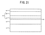
- FIG. 21 is a cross sectional view showing an important part of a modification of the first and second embodiments of the magnetic recording medium.
- those parts which are the same as those corresponding parts in FIG. 4 are designated by the same reference numerals, and a description thereof will be omitted.
- This modification may be applied to each of the first and second embodiments of the magnetic recording medium described above. As shown in FIG. 21, this modification additionally includes an intermediate layer 23 which is provided between the underlayer 12 and the initial layer 21 of the magnetic layer 13.
- the intermediate layer 23 is made of a CoCr-based alloy, for example, and has a thickness of approximately 1 to 5 nm.
- the intermediate layer 23 may also be made of a hcp non-magnetic or slightly magnetic material. The provision of the intermediate layer 23 helps increase the coercivity Hc and reduce the media noise.
Landscapes
- Magnetic Record Carriers (AREA)
Applications Claiming Priority (2)
| Application Number | Priority Date | Filing Date | Title |
|---|---|---|---|
| JP2000107077 | 2000-04-07 | ||
| JP2000107077A JP4028154B2 (ja) | 2000-04-07 | 2000-04-07 | 磁気記録媒体及び磁気記憶装置 |
Publications (1)
| Publication Number | Publication Date |
|---|---|
| EP1143420A1 true EP1143420A1 (en) | 2001-10-10 |
Family
ID=18620122
Family Applications (1)
| Application Number | Title | Priority Date | Filing Date |
|---|---|---|---|
| EP00310525A Withdrawn EP1143420A1 (en) | 2000-04-07 | 2000-11-28 | Magnetic recording medium and magnetic storage apparatus |
Country Status (4)
| Country | Link |
|---|---|
| US (1) | US6610424B1 (ko) |
| EP (1) | EP1143420A1 (ko) |
| JP (1) | JP4028154B2 (ko) |
| KR (1) | KR100778812B1 (ko) |
Cited By (1)
| Publication number | Priority date | Publication date | Assignee | Title |
|---|---|---|---|---|
| EP1343147A2 (en) * | 2002-03-06 | 2003-09-10 | Fujitsu Limited | Magnetic recording medium and magnetic storage apparatus |
Families Citing this family (11)
| Publication number | Priority date | Publication date | Assignee | Title |
|---|---|---|---|---|
| EP1863017A3 (en) * | 2000-11-29 | 2008-01-23 | Fujitsu Ltd. | Magnetic recording medium and magnetic storage apparatus |
| JP2002208126A (ja) * | 2001-01-05 | 2002-07-26 | Fuji Electric Co Ltd | 磁気記録媒体、磁気記録媒体の製造方法、および磁気記録装置 |
| JP2004079062A (ja) | 2002-08-15 | 2004-03-11 | Fujitsu Ltd | 磁気記録媒体 |
| US7504166B2 (en) * | 2003-06-16 | 2009-03-17 | Seagate Technology Llc | Magnetic recording media having five element alloy deposited using pulsed direct current sputtering |
| US7592079B1 (en) | 2003-07-03 | 2009-09-22 | Seagate Technology Llc | Method to improve remanence-squareness-thickness-product and coercivity profiles in magnetic media |
| US7393601B1 (en) | 2004-08-05 | 2008-07-01 | Seagate Technology Llc | Weak antiferromagnetically coupled media with a five element magnetic alloy and a low moment stabilizing layer |
| JP2006309922A (ja) * | 2005-03-31 | 2006-11-09 | Fujitsu Ltd | 磁気記録媒体及び磁気記録装置 |
| JP2008159144A (ja) * | 2006-12-22 | 2008-07-10 | Fuji Electric Device Technology Co Ltd | 長手磁気記録媒体 |
| KR101683135B1 (ko) * | 2009-03-13 | 2016-12-06 | 시게이트 테크놀로지 엘엘씨 | 수직자기기록매체 |
| US8580409B2 (en) * | 2009-11-09 | 2013-11-12 | HGST Netherlands B.V. | Perpendicular magnetic recording media having a dual onset layer |
| US9093101B2 (en) | 2011-02-28 | 2015-07-28 | Seagate Technology Llc | Stack including a magnetic zero layer |
Citations (8)
| Publication number | Priority date | Publication date | Assignee | Title |
|---|---|---|---|---|
| US4792486A (en) * | 1985-03-28 | 1988-12-20 | Victor Company Of Japan, Ltd. | Perpendicular magnetic recording medium |
| US4798765A (en) * | 1985-03-28 | 1989-01-17 | Victor Company Of Japan Ltd. | Perpendicular magnetic recording medium |
| US5147732A (en) * | 1988-09-28 | 1992-09-15 | Hitachi, Ltd. | Longitudinal magnetic recording media and magnetic memory units |
| US5772857A (en) * | 1995-11-21 | 1998-06-30 | Seagate Technology, Inc. | Method of manufacturing CoCrTa/CoCrTaPt bi-layer magnetic thin films |
| US5849386A (en) * | 1996-04-26 | 1998-12-15 | Hmt Technology Corporation | Magnetic recording medium having a prelayer |
| US5851643A (en) * | 1993-11-11 | 1998-12-22 | Hitachi, Ltd. | Magnetic recording media and magnetic recording read-back system which uses such media |
| US5922442A (en) * | 1996-04-26 | 1999-07-13 | Hmt Technology Corporation | Magnetic recording medium having a CoCr alloy interlayer of a low saturation magnetization |
| US6168861B1 (en) * | 1997-12-12 | 2001-01-02 | Seagate Technology Llc | High coercivity, high signal-to-noise ratio dual magnetic layer media |
Family Cites Families (3)
| Publication number | Priority date | Publication date | Assignee | Title |
|---|---|---|---|---|
| US5848386A (en) | 1996-05-28 | 1998-12-08 | Ricoh Company, Ltd. | Method and system for translating documents using different translation resources for different portions of the documents |
| US5820963A (en) | 1997-04-02 | 1998-10-13 | Komag, Incorporated | Method of manufacturing a thin film magnetic recording medium having low MrT value and high coercivity |
| JPH11238221A (ja) * | 1998-02-20 | 1999-08-31 | Fujitsu Ltd | 磁気記録媒体及び磁気ディスク装置 |
-
2000
- 2000-04-07 JP JP2000107077A patent/JP4028154B2/ja not_active Expired - Fee Related
- 2000-11-22 US US09/721,097 patent/US6610424B1/en not_active Expired - Fee Related
- 2000-11-28 EP EP00310525A patent/EP1143420A1/en not_active Withdrawn
- 2000-12-04 KR KR1020000073049A patent/KR100778812B1/ko not_active IP Right Cessation
Patent Citations (9)
| Publication number | Priority date | Publication date | Assignee | Title |
|---|---|---|---|---|
| US4792486A (en) * | 1985-03-28 | 1988-12-20 | Victor Company Of Japan, Ltd. | Perpendicular magnetic recording medium |
| US4798765A (en) * | 1985-03-28 | 1989-01-17 | Victor Company Of Japan Ltd. | Perpendicular magnetic recording medium |
| US5147732A (en) * | 1988-09-28 | 1992-09-15 | Hitachi, Ltd. | Longitudinal magnetic recording media and magnetic memory units |
| US5851643A (en) * | 1993-11-11 | 1998-12-22 | Hitachi, Ltd. | Magnetic recording media and magnetic recording read-back system which uses such media |
| US5772857A (en) * | 1995-11-21 | 1998-06-30 | Seagate Technology, Inc. | Method of manufacturing CoCrTa/CoCrTaPt bi-layer magnetic thin films |
| US5952097A (en) * | 1995-11-21 | 1999-09-14 | Seagate Technology, Inc. | CoCrTa/Cocrptta bi-layer magnetic thin films |
| US5849386A (en) * | 1996-04-26 | 1998-12-15 | Hmt Technology Corporation | Magnetic recording medium having a prelayer |
| US5922442A (en) * | 1996-04-26 | 1999-07-13 | Hmt Technology Corporation | Magnetic recording medium having a CoCr alloy interlayer of a low saturation magnetization |
| US6168861B1 (en) * | 1997-12-12 | 2001-01-02 | Seagate Technology Llc | High coercivity, high signal-to-noise ratio dual magnetic layer media |
Cited By (3)
| Publication number | Priority date | Publication date | Assignee | Title |
|---|---|---|---|---|
| EP1343147A2 (en) * | 2002-03-06 | 2003-09-10 | Fujitsu Limited | Magnetic recording medium and magnetic storage apparatus |
| EP1343147A3 (en) * | 2002-03-06 | 2005-04-13 | Fujitsu Limited | Magnetic recording medium and magnetic storage apparatus |
| US6881496B2 (en) | 2002-03-06 | 2005-04-19 | Fujitsu Limited | Antiferromagnetically coupled magnetic recording medium possessing three coupled magnetic layers and magnetic storage apparatus |
Also Published As
| Publication number | Publication date |
|---|---|
| US6610424B1 (en) | 2003-08-26 |
| KR100778812B1 (ko) | 2007-11-22 |
| KR20010090701A (ko) | 2001-10-19 |
| JP2001291223A (ja) | 2001-10-19 |
| JP4028154B2 (ja) | 2007-12-26 |
Similar Documents
| Publication | Publication Date | Title |
|---|---|---|
| JP4761224B2 (ja) | 垂直磁気記録媒体 | |
| EP1298648B1 (en) | Magnetic recording medium and magnetic storage apparatus | |
| EP1346348B1 (en) | Magnetic recording medium and magnetic storage apparatus | |
| US20090226763A1 (en) | Perpendicular magnetic recording medium, production process thereof, and magnetic recording and reproducing apparatus | |
| US20050129985A1 (en) | Perpendicular magnetic recording media | |
| US6610424B1 (en) | Magnetic recording medium and magnetic storage apparatus | |
| US7427446B2 (en) | Magnetic recording medium with antiparallel magnetic layers and CrN based underlayer, magnetic storage apparatus and method of producing magnetic recording medium | |
| US9972352B2 (en) | Antiferromagnetic coupling layers | |
| US7241517B2 (en) | Magnetic recording medium and magnetic storage apparatus | |
| US6551728B1 (en) | Magnetic recording medium and magnetic storage apparatus | |
| KR20020060332A (ko) | 초고밀도기록을 위한 수직 기록용 자성 박막 | |
| US6677051B1 (en) | Magnetic recording medium with dual magnetic layers having specific composition requirements and a magnetic storage apparatus | |
| JP5516283B2 (ja) | 垂直磁気記録媒体 | |
| JP4634267B2 (ja) | 垂直磁気記録媒体 | |
| US7049013B2 (en) | Magnetic recording medium and method of producing the same, and magnetic storage apparatus | |
| JP3987080B2 (ja) | 磁気記録媒体及び磁気記憶装置 | |
| JP4534402B2 (ja) | 垂直磁気記録媒体及びその製造方法 | |
| JP2005317199A (ja) | 磁気記録媒体及び磁気記憶装置 | |
| JP2000200409A (ja) | 磁気記録媒体 |
Legal Events
| Date | Code | Title | Description |
|---|---|---|---|
| PUAI | Public reference made under article 153(3) epc to a published international application that has entered the european phase |
Free format text: ORIGINAL CODE: 0009012 |
|
| AK | Designated contracting states |
Kind code of ref document: A1 Designated state(s): AT BE CH CY DE DK ES FI FR GB GR IE IT LI LU MC NL PT SE TR Kind code of ref document: A1 Designated state(s): DE FR GB |
|
| AX | Request for extension of the european patent |
Free format text: AL;LT;LV;MK;RO;SI |
|
| 17P | Request for examination filed |
Effective date: 20011029 |
|
| AKX | Designation fees paid |
Free format text: DE FR GB |
|
| 17Q | First examination report despatched |
Effective date: 20061115 |
|
| RAP1 | Party data changed (applicant data changed or rights of an application transferred) |
Owner name: SHOWA DENKO K.K. |
|
| GRAP | Despatch of communication of intention to grant a patent |
Free format text: ORIGINAL CODE: EPIDOSNIGR1 |
|
| STAA | Information on the status of an ep patent application or granted ep patent |
Free format text: STATUS: THE APPLICATION IS DEEMED TO BE WITHDRAWN |
|
| 18D | Application deemed to be withdrawn |
Effective date: 20110601 |