EP1143260A2 - Vorrichtung zur Funkpeilung und Positionsbestimmung - Google Patents
Vorrichtung zur Funkpeilung und Positionsbestimmung Download PDFInfo
- Publication number
- EP1143260A2 EP1143260A2 EP01301673A EP01301673A EP1143260A2 EP 1143260 A2 EP1143260 A2 EP 1143260A2 EP 01301673 A EP01301673 A EP 01301673A EP 01301673 A EP01301673 A EP 01301673A EP 1143260 A2 EP1143260 A2 EP 1143260A2
- Authority
- EP
- European Patent Office
- Prior art keywords
- output
- directional antenna
- receiving
- radio wave
- sum
- Prior art date
- Legal status (The legal status is an assumption and is not a legal conclusion. Google has not performed a legal analysis and makes no representation as to the accuracy of the status listed.)
- Withdrawn
Links
Images


Classifications
-
- G—PHYSICS
- G01—MEASURING; TESTING
- G01S—RADIO DIRECTION-FINDING; RADIO NAVIGATION; DETERMINING DISTANCE OR VELOCITY BY USE OF RADIO WAVES; LOCATING OR PRESENCE-DETECTING BY USE OF THE REFLECTION OR RERADIATION OF RADIO WAVES; ANALOGOUS ARRANGEMENTS USING OTHER WAVES
- G01S3/00—Direction-finders for determining the direction from which infrasonic, sonic, ultrasonic or electromagnetic waves, or particle emission, not having a directional significance, are being received
- G01S3/02—Direction-finders for determining the direction from which infrasonic, sonic, ultrasonic or electromagnetic waves, or particle emission, not having a directional significance, are being received using radio waves
- G01S3/14—Systems for determining direction or deviation from predetermined direction
- G01S3/28—Systems for determining direction or deviation from predetermined direction using amplitude comparison of signals derived simultaneously from receiving antennas or antenna systems having differently-oriented directivity characteristics
- G01S3/32—Systems for determining direction or deviation from predetermined direction using amplitude comparison of signals derived simultaneously from receiving antennas or antenna systems having differently-oriented directivity characteristics derived from different combinations of signals from separate antennas, e.g. comparing sum with difference
- G01S3/36—Systems for determining direction or deviation from predetermined direction using amplitude comparison of signals derived simultaneously from receiving antennas or antenna systems having differently-oriented directivity characteristics derived from different combinations of signals from separate antennas, e.g. comparing sum with difference the separate antennas having differently-oriented directivity characteristics
-
- H—ELECTRICITY
- H01—ELECTRIC ELEMENTS
- H01Q—ANTENNAS, i.e. RADIO AERIALS
- H01Q21/00—Antenna arrays or systems
- H01Q21/06—Arrays of individually energised antenna units similarly polarised and spaced apart
- H01Q21/08—Arrays of individually energised antenna units similarly polarised and spaced apart the units being spaced along or adjacent to a rectilinear path
-
- H—ELECTRICITY
- H01—ELECTRIC ELEMENTS
- H01Q—ANTENNAS, i.e. RADIO AERIALS
- H01Q25/00—Antennas or antenna systems providing at least two radiating patterns
- H01Q25/02—Antennas or antenna systems providing at least two radiating patterns providing sum and difference patterns
-
- H—ELECTRICITY
- H01—ELECTRIC ELEMENTS
- H01Q—ANTENNAS, i.e. RADIO AERIALS
- H01Q3/00—Arrangements for changing or varying the orientation or the shape of the directional pattern of the waves radiated from an antenna or antenna system
- H01Q3/26—Arrangements for changing or varying the orientation or the shape of the directional pattern of the waves radiated from an antenna or antenna system varying the relative phase or relative amplitude of energisation between two or more active radiating elements; varying the distribution of energy across a radiating aperture
- H01Q3/28—Arrangements for changing or varying the orientation or the shape of the directional pattern of the waves radiated from an antenna or antenna system varying the relative phase or relative amplitude of energisation between two or more active radiating elements; varying the distribution of energy across a radiating aperture varying the amplitude
-
- H—ELECTRICITY
- H01—ELECTRIC ELEMENTS
- H01Q—ANTENNAS, i.e. RADIO AERIALS
- H01Q3/00—Arrangements for changing or varying the orientation or the shape of the directional pattern of the waves radiated from an antenna or antenna system
- H01Q3/26—Arrangements for changing or varying the orientation or the shape of the directional pattern of the waves radiated from an antenna or antenna system varying the relative phase or relative amplitude of energisation between two or more active radiating elements; varying the distribution of energy across a radiating aperture
- H01Q3/30—Arrangements for changing or varying the orientation or the shape of the directional pattern of the waves radiated from an antenna or antenna system varying the relative phase or relative amplitude of energisation between two or more active radiating elements; varying the distribution of energy across a radiating aperture varying the relative phase between the radiating elements of an array
- H01Q3/34—Arrangements for changing or varying the orientation or the shape of the directional pattern of the waves radiated from an antenna or antenna system varying the relative phase or relative amplitude of energisation between two or more active radiating elements; varying the distribution of energy across a radiating aperture varying the relative phase between the radiating elements of an array by electrical means
- H01Q3/40—Arrangements for changing or varying the orientation or the shape of the directional pattern of the waves radiated from an antenna or antenna system varying the relative phase or relative amplitude of energisation between two or more active radiating elements; varying the distribution of energy across a radiating aperture varying the relative phase between the radiating elements of an array by electrical means with phasing matrix
-
- G—PHYSICS
- G01—MEASURING; TESTING
- G01S—RADIO DIRECTION-FINDING; RADIO NAVIGATION; DETERMINING DISTANCE OR VELOCITY BY USE OF RADIO WAVES; LOCATING OR PRESENCE-DETECTING BY USE OF THE REFLECTION OR RERADIATION OF RADIO WAVES; ANALOGOUS ARRANGEMENTS USING OTHER WAVES
- G01S5/00—Position-fixing by co-ordinating two or more direction or position line determinations; Position-fixing by co-ordinating two or more distance determinations
- G01S5/02—Position-fixing by co-ordinating two or more direction or position line determinations; Position-fixing by co-ordinating two or more distance determinations using radio waves
- G01S5/04—Position of source determined by a plurality of spaced direction-finders
Definitions
- the present invention relates to a direction and position finding apparatus which receives an radio wave and determines a direction of arrival and a position of an emission source thereof with high accuracy.
- One of the well-known basic direction finding apparatuses to detect a direction of arrival of radio wave is, for example, Yagi antenna which detects the direction of arrival of the radio wave using a directional antenna.
- Another direction finding apparatus is disclosed in the Japanese Patent Application No. H3-67789, which uses a non-directional antenna and two directional antennas to determine an approximate direction based on an output corresponding to a summing pattern of the two directional antenna patterns and another output from the non-directional antenna, and further to perform a direction finding based on the output corresponding to the summing pattern and another output corresponding to a differential pattern of the two directional antenna patterns.
- the present invention is made to solve the problems described above, and an object thereof is to provide a direction and position finding apparatus capable of not only detecting a direction of arrival of radio wave with high accuracy, but also performing a highly accurate position finding of an emission source thereof.
- An invention defined in claim 1 of the present invention provides a direction and position finding apparatus comprising: a first directional antenna which rotates with a desired wave angle; a first phase sum and difference combining means for outputting a sum and a difference of outputs from said first directional antenna; a first differential gain control means for controlling a gain of the differential component of the output of said first directional antenna; a first receiving means for receiving the sum component from said first phase sum and difference combining means; a second receiving means for receiving an output from said first differential gain control means; a first subtraction means for subtracting one output from the other output of said first and said second receiving means; a first calculation means for determining a direction of arrival of radio wave based on an output from said first subtraction means; a second directional antenna which rotates with a desired wave angle; a second phase sum and difference combining means for outputting a sum and a difference of outputs of said second directional antenna; a second differential gain control means for controlling a gain of the differential component of the output from said second directional antenna
- An invention defined in claim 2 of the present invention provides a direction and position finding apparatus in accordance with claim 1, in which said directional antennas use at least two vertical polarized waves, and thereby, said apparatus constructed as described above also provides an advantageous effect that it can determine the direction and the position of the emission source of the radio wave based on the summing outputs and the differential outputs of the outputs from the two vertical polarized wave antennas.
- An invention defined in claim 3 of the present invention provides a direction and position finding apparatus in accordance with claim 1, in which said apparatus uses a vertical polarized wave directional antenna with acute horizontal directivity and a vertical polarized wave directional antenna with acute vertical directivity, and thereby, said apparatus constructed as described above also provides an advantageous effect that it can determine the direction and the position of the emission source of the radio wave based on the summing output and the differential output of the output from the vertical polarized wave directional antenna with acute vertical directivity and also by the summing output and the differential output of an antenna pattern of the vertical polarized wave directional antenna with acute horizontal directivity.
- An invention defined in claim 4 of the present invention provides a direction and position finding apparatus in accordance with claim 1, in which each of said first and said second phase sum and difference combining means can vary a phase difference in the output from each said directional antennas, and thereby, said apparatus constructed as described above also provides an advantageous effect that, since a setting of the phase difference can be varied, said apparatus can determine the direction and the position of the emission source of the radio wave based on the summing output and the differential output of the output from the directional antenna, which have been generated as a resultant formed by shifting a phase difference.
- An invention defined in claim 5 of the present invention provides a direction and position finding apparatus in accordance with claim 1, in which the position of the emission source of the radio wave is determined by controlling the gain of the differential component of the output from the directional antenna, and thereby, said apparatus constructed as described above also provides an advantageous effect that it can determine the direction of arrival of the radio wave by interlockingly rotating those two directional antennas to maximize the summing output and also determine the position of the emission source of the radio wave by controlling a wave angle while controlling a gain of the differential output.
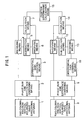
- Fig. 1 is a block diagram of a direction and position finding apparatus according to the present invention.
- this direction and position finding apparatus comprises a one-column two-row vertical polarized wave directional antenna 1 with acute vertical directivity and a two-column one-row vertical polarized wave directional antenna 8 with acute horizontal directivity.
- the directional antenna 1 and another directional antenna 8 can interlockingly rotate with respective predetermined wave angles.
- Each of phase sum and difference combining means 2 and 9 respectively receives a signal received by each of the directional antennas 1 and 8, and generates summing signal and differential signal of each of those two received signals to output them.
- each of the phase sum and difference combining means 2 and 9 can respectively set the phase difference of each of these two directional antennas 1 and 8 to a desired value.
- Each of gain control means 3 and 10 respectively controls gain of the differential signal outputted from each of the phase sum and difference combining means 2 and 9.
- Each of receiving means 4 and 11 respectively detects the summing signal outputted from each of the phase sum and difference combining means 2 and 9, and each of receiving means 6 and 13 respectively detects the gain controlled differential signal outputted from each of the gain control means 3 and 10.
- Each of subtraction means 5 and 12 respectively calculates difference between the detected output from each of the receiving means 4 and 11 and that from each of the receiving means 6 and 13.
- Each of calculation means 7 and 14 respectively determines a direction of arrival of radio wave based on the output from each of the subtraction means 5 and 12 and each of these results is applied to a position determining means 15 to determine a position of an emission source of the radio wave.
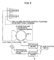
- Figs. 2 and 3 respectively depict cases where each of the phase sum and difference combining means 2 and 9 in Fig. 1 combines the signals received by the directional antenna 1 or 8 with the phases shifted to each other by ⁇ /4 to form the summing signal, and with the phase shifted to each other by 3 ⁇ /4 to form the differential signal.
- the one-column two-row vertical polarized wave directional antenna 1 and the two-column one-row vertical polarized wave directional antenna 8, which are oriented toward the same direction and have predetermined directivities respectively, and are adjustable in their wave angles, and also are rotated interlockingly with each other, output received signals corresponding to respective horizontal and vertical planes (hereafter each being referred to as an antenna pattern).
- Each of the antenna patterns of the respective directional antennas 1 and 8 is inputted to the phase sum and difference combining means 2 or 9 respectively and is divided into a summing signal output (hereafter referred to as a ⁇ pattern) formed by combining the received signals with a phase shifted by ⁇ /4 to each other and a differential signal output (hereafter referred to as a ⁇ pattern) formed by combining them with a phase shifted by 3 ⁇ /4 to each other.
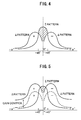
- the antenna patterns of the respective directional antenna 1 and 8 are shown in Figs. 4 and 5.
- reference character ⁇ designates an azimuth angle.
- Each of the ⁇ patterns outputted from the phase sum and difference combining means 2 and 9 is inputted to the gain control means 3 or 10 and after the gain is controlled, inputted to the receiving means 6 or 13 respectively.
- the ⁇ patterns are inputted to the receiving means 4 and 11 without any modification.
- the receiving means 4, 6 and the receiving means 11, 13 respectively output detection signals of the summing outputs or those of the differential outputs to the subtraction means 5 or 12.
- the subtraction means 5 and 12 respectively subtract the detection signals of the differential outputs from those of the summing outputs to generate angle properties of those differences (hereafter referred to as a ⁇ - ⁇ pattern), and respectively output the angle properties to the calculation means 7 or 14.
- a ⁇ - ⁇ pattern formed by a difference therebetween shows a steep variation in level in the vicinity of a front side of the antenna. This indicates that the beam width of the antenna is equivalently getting narrower than the ⁇ pattern. Accordingly, a highly accurate direction finding can be achieved by using an output corresponding to this ⁇ - ⁇ pattern.
- the ⁇ - ⁇ pattern can be shifted by employing an amplifier in the gain control means and thereby manually controlling or automatically controlling using AGC (automatic Gain Control) means a gain of the ⁇ pattern.
- AGC Automatic Gain Control
- Fig. 5 shows that the higher ⁇ - ⁇ pattern indicates more steep directivity to obtain higher accuracy, and the lower ⁇ - ⁇ pattern indicates more moderate directivity. This gain control makes it possible to detect a maximum point of an arrival position of the radio wave.
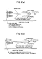
- Fig. 6(a) shows a directivity of one-column two-row vertical polarized wave directional antenna 1
- Fig. 6(b) shows a directivity of two-column one-row vertical polarized wave directional antenna 8.
- the directivity is designated as being directed in up and down (vertical) direction and left and right (horizontal) direction. Because of the combination of the directional lines, the one-column two-row vertical polarized wave directional antenna 1 shows a steep shaped output of ⁇ - ⁇ pattern in its directivity along the up and down (vertical) direction.
- the two-column one-row vertical polarized wave directional antenna 8 shows a steep shaped output of ⁇ - ⁇ pattern in its directivity along the left and right (horizontal) direction. Combining these directivities allows to detect a desired point in a space.
- the calculation means 7 and 14 shown in Fig. 1 respectively calculate the level of the ⁇ pattern as rotating the directional antennas 1 and 8 to determine the directions with the maximum levels thereof and thus to detect the direction of arrival of the radio wave. Further by controlling the outputs of the ⁇ pattern using the differential gain control means 3 and 10 as well as controlling the wave angles of the directional antennas 1 and 8, the position can be determined.
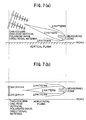
- Fig. 7 shows an embodiment for measuring a direction and a position of an emission source of an radio wave along an extending direction of a road by a direction and position finding apparatus in accordance with the present invention.
- the upper (a) is a side elevation view and the lower (b) is a plan view.
- the directional antenna is set to have a wave angle to determine a measuring range on the road surface. Controlling an azimuth angle to maximize the ⁇ pattern and controlling a gain of the ⁇ pattern allow to measure the position of the emission source of the radio wave.
- a range on the road a road width
- the position of the emission source of the radio wave can be measured by horizontally rotating the antenna in the left and right direction.
- Fig. 8 is a plan view illustrating alternative embodiment.
- the measuring range can be determined by setting the directional antenna to have the wave angle. Then, controlling the wave angle to maximize the ⁇ pattern and controlling the gain of the ⁇ pattern allow to measure the position range of the emission source of the radio wave. Furthermore, controlling the wave angle of the directional antenna and horizontally rotating the antenna in the left and right direction allow to measure the position of the emission source of the radio wave in the wider range on traffic lane.
- the apparatus according to the present invention is constructed so that the direction of arrival of the radio wave is determined by interlockingly rotating two directional antennas to maximize the ⁇ pattern of the directivity in each of the two directional antennas and the position of the emission source of the radio wave is determined by controlling the wave angle while controlling the gain of the ⁇ pattern output, such an advantageous effect can be obtained that a highly accurate direction and position finding operation can be performed with a simple antenna configuration.
Landscapes
- Physics & Mathematics (AREA)
- Engineering & Computer Science (AREA)
- General Physics & Mathematics (AREA)
- Radar, Positioning & Navigation (AREA)
- Remote Sensing (AREA)
- Variable-Direction Aerials And Aerial Arrays (AREA)
- Radar Systems Or Details Thereof (AREA)
Applications Claiming Priority (2)
| Application Number | Priority Date | Filing Date | Title |
|---|---|---|---|
| JP2000061351 | 2000-03-07 | ||
| JP2000061351A JP2001249173A (ja) | 2000-03-07 | 2000-03-07 | 電波方位・位置探知装置 |
Publications (2)
| Publication Number | Publication Date |
|---|---|
| EP1143260A2 true EP1143260A2 (de) | 2001-10-10 |
| EP1143260A3 EP1143260A3 (de) | 2002-12-11 |
Family
ID=18581498
Family Applications (1)
| Application Number | Title | Priority Date | Filing Date |
|---|---|---|---|
| EP01301673A Withdrawn EP1143260A3 (de) | 2000-03-07 | 2001-02-23 | Vorrichtung zur Funkpeilung und Positionsbestimmung |
Country Status (4)
| Country | Link |
|---|---|
| US (1) | US6373435B2 (de) |
| EP (1) | EP1143260A3 (de) |
| JP (1) | JP2001249173A (de) |
| CA (1) | CA2332688A1 (de) |
Cited By (4)
| Publication number | Priority date | Publication date | Assignee | Title |
|---|---|---|---|---|
| GB2496030A (en) * | 2011-10-26 | 2013-05-01 | Boeing Co | Monopulse radar |
| WO2021133872A1 (en) * | 2019-12-23 | 2021-07-01 | Radius Networks, Inc. | High confidence isolated presence detection in fine resolution region |
| US11532032B2 (en) | 2019-02-01 | 2022-12-20 | Radius Networks, Inc. | Location sensitive queues management |
| US11823165B2 (en) | 2020-02-05 | 2023-11-21 | Radius Networks, Inc. | Associating prior arrangements with on-premise manual transactions and concomitant presence of actor's presence-advertising emitter in fine resolution region |
Families Citing this family (8)
| Publication number | Priority date | Publication date | Assignee | Title |
|---|---|---|---|---|
| JP2003107144A (ja) * | 2001-09-28 | 2003-04-09 | Matsushita Electric Ind Co Ltd | 電波方位位置探知装置 |
| JP2009198363A (ja) * | 2008-02-22 | 2009-09-03 | Omron Corp | 電波探知装置および方法 |
| US9366756B2 (en) * | 2008-12-06 | 2016-06-14 | Thales Canada Inc | RF tag reader for accurate position determination |
| JP5025739B2 (ja) * | 2010-01-05 | 2012-09-12 | 中国電力株式会社 | 無線通信システム |
| RU2476900C1 (ru) * | 2011-10-27 | 2013-02-27 | Научно-Исследовательский Испытательный Центр Систем Связи Федерального Государственного Учреждения "27 Центральный Научно-Исследовательский Институт Минобороны России" | Способ определения координат источников радиоизлучений |
| KR101747789B1 (ko) * | 2016-04-14 | 2017-06-15 | 국방과학연구소 | 듀얼편파안테나와 가변 이득감쇠기를 이용한 선형편파 추적 시스템 및 그 제어 방법 |
| DE112017007937B4 (de) * | 2017-10-23 | 2022-03-03 | Mitsubishi Electric Corporation | Kommunikationseinrichtung, Steuerungsverfahren und Steuerungsprogramm |
| CN110109052B (zh) * | 2019-05-23 | 2021-12-31 | 中国人民解放军战略支援部队信息工程大学 | 一种阵元位置误差条件下的目标测向和阵元位置估计方法 |
Family Cites Families (5)
| Publication number | Priority date | Publication date | Assignee | Title |
|---|---|---|---|---|
| US4387373A (en) * | 1977-04-21 | 1983-06-07 | Westinghouse Electric Corp. | Synthetic monopulse radar |
| GB2253107B (en) * | 1982-03-05 | 1993-01-13 | Philips Electronic Associated | Locating moving radio sources |
| JPH0238886A (ja) * | 1988-07-28 | 1990-02-08 | Mitsubishi Electric Corp | レーダ装置 |
| US5526001A (en) * | 1992-12-11 | 1996-06-11 | Litton Systems Inc. | Precise bearings only geolocation in systems with large measurements bias errors |
| JP3522153B2 (ja) * | 1999-05-28 | 2004-04-26 | 松下電器産業株式会社 | 方位・位置探知装置 |
-
2000
- 2000-03-07 JP JP2000061351A patent/JP2001249173A/ja active Pending
-
2001
- 2001-01-26 CA CA002332688A patent/CA2332688A1/en not_active Abandoned
- 2001-01-31 US US09/772,932 patent/US6373435B2/en not_active Expired - Fee Related
- 2001-02-23 EP EP01301673A patent/EP1143260A3/de not_active Withdrawn
Cited By (6)
| Publication number | Priority date | Publication date | Assignee | Title |
|---|---|---|---|---|
| GB2496030A (en) * | 2011-10-26 | 2013-05-01 | Boeing Co | Monopulse radar |
| US8633850B2 (en) | 2011-10-26 | 2014-01-21 | The Boeing Company | Identifying a location of a target object using a monopulse radar system and space-time adaptive processing (STAP) |
| US11532032B2 (en) | 2019-02-01 | 2022-12-20 | Radius Networks, Inc. | Location sensitive queues management |
| WO2021133872A1 (en) * | 2019-12-23 | 2021-07-01 | Radius Networks, Inc. | High confidence isolated presence detection in fine resolution region |
| US11609319B2 (en) | 2019-12-23 | 2023-03-21 | Radius Networks, Inc. | High confidence isolated presence detection in fine resolution region |
| US11823165B2 (en) | 2020-02-05 | 2023-11-21 | Radius Networks, Inc. | Associating prior arrangements with on-premise manual transactions and concomitant presence of actor's presence-advertising emitter in fine resolution region |
Also Published As
| Publication number | Publication date |
|---|---|
| JP2001249173A (ja) | 2001-09-14 |
| EP1143260A3 (de) | 2002-12-11 |
| US6373435B2 (en) | 2002-04-16 |
| CA2332688A1 (en) | 2001-09-07 |
| US20010020916A1 (en) | 2001-09-13 |
Similar Documents
| Publication | Publication Date | Title |
|---|---|---|
| US6373435B2 (en) | Radio direction and position finding apparatus | |
| US7193930B2 (en) | Quantitative echo sounder and method of quantitative sounding of fish | |
| US4706031A (en) | Method and system for detecting an object with a radio wave | |
| US10551494B2 (en) | Road information detection apparatus and road information detection method | |
| US6759982B2 (en) | Radio direction and position finding apparatus | |
| EP0241992A2 (de) | Funkpeiler | |
| WO1997001767A1 (en) | Vehicle-ground surface measurement system | |
| JPH01320486A (ja) | 水中の物体、特に係留機雷のソナーによる識別方法 | |
| JP3522153B2 (ja) | 方位・位置探知装置 | |
| KR20190054654A (ko) | 차량용 레이더 제어 장치 및 방법 | |
| HK1067707A (en) | Radiowave location detector for bearing and position determination | |
| WO2019150483A1 (ja) | 速度算出装置、速度算出方法、及び、プログラム | |
| KR102577806B1 (ko) | 빔 조향 전파고도계 및 컨벡스 최적화를 이용한 빔 조향 방법 | |
| RU2235830C1 (ru) | Способ определения местоположения пробойника в грунте и устройство для его реализации | |
| JP2005121421A (ja) | 海上用rcs計測装置 | |
| RU2073878C1 (ru) | Фазовый пеленгатор сканирующих источников | |
| NO822326L (no) | Radiopeilearrangement. | |
| JP2591482B2 (ja) | 目標検出回路 | |
| JP2619144B2 (ja) | 方向探知装置 | |
| RU2206906C1 (ru) | Способ определения местоположения пробойника в грунте и устройство для его реализации | |
| CA1119705A (en) | Method and arrangement for lateral determination with two-channel direction finders | |
| RU2638174C1 (ru) | Способ определения угловых координат цели с помощью линейной антенной решетки | |
| JP2001264405A (ja) | 移動体の3次元位置及び3次元角度の検出方法とその検出装置 | |
| JP2002181912A (ja) | 方探装置 | |
| SE411596B (sv) | For elektromagnetisk stralning kenslig anordning, inrettad att lokalisera en sendare |
Legal Events
| Date | Code | Title | Description |
|---|---|---|---|
| PUAI | Public reference made under article 153(3) epc to a published international application that has entered the european phase |
Free format text: ORIGINAL CODE: 0009012 |
|
| AK | Designated contracting states |
Kind code of ref document: A2 Designated state(s): AT BE CH CY DE DK ES FI FR GB GR IE IT LI LU MC NL PT SE TR |
|
| AX | Request for extension of the european patent |
Free format text: AL;LT;LV;MK;RO;SI |
|
| PUAL | Search report despatched |
Free format text: ORIGINAL CODE: 0009013 |
|
| AK | Designated contracting states |
Kind code of ref document: A3 Designated state(s): AT BE CH CY DE DK ES FI FR GB GR IE IT LI LU MC NL PT SE TR |
|
| AX | Request for extension of the european patent |
Free format text: AL;LT;LV;MK;RO;SI |
|
| 17P | Request for examination filed |
Effective date: 20030605 |
|
| AKX | Designation fees paid |
Designated state(s): DE FR GB IT |
|
| STAA | Information on the status of an ep patent application or granted ep patent |
Free format text: STATUS: THE APPLICATION HAS BEEN WITHDRAWN |
|
| 18W | Application withdrawn |
Effective date: 20060919 |