EP1142653A2 - Roll cooling and/or lubricating device for cold strip rolling mills, in particular fine strip and foil rolling mills - Google Patents
Roll cooling and/or lubricating device for cold strip rolling mills, in particular fine strip and foil rolling mills Download PDFInfo
- Publication number
- EP1142653A2 EP1142653A2 EP01107353A EP01107353A EP1142653A2 EP 1142653 A2 EP1142653 A2 EP 1142653A2 EP 01107353 A EP01107353 A EP 01107353A EP 01107353 A EP01107353 A EP 01107353A EP 1142653 A2 EP1142653 A2 EP 1142653A2
- Authority
- EP
- European Patent Office
- Prior art keywords
- nozzle bars
- roll
- strip
- nozzle
- longitudinal axis
- Prior art date
- Legal status (The legal status is an assumption and is not a legal conclusion. Google has not performed a legal analysis and makes no representation as to the accuracy of the status listed.)
- Granted
Links
Images


Classifications
-
- B—PERFORMING OPERATIONS; TRANSPORTING
- B21—MECHANICAL METAL-WORKING WITHOUT ESSENTIALLY REMOVING MATERIAL; PUNCHING METAL
- B21B—ROLLING OF METAL
- B21B37/00—Control devices or methods specially adapted for metal-rolling mills or the work produced thereby
- B21B37/28—Control of flatness or profile during rolling of strip, sheets or plates
- B21B37/30—Control of flatness or profile during rolling of strip, sheets or plates using roll camber control
- B21B37/32—Control of flatness or profile during rolling of strip, sheets or plates using roll camber control by cooling, heating or lubricating the rolls
-
- B—PERFORMING OPERATIONS; TRANSPORTING
- B21—MECHANICAL METAL-WORKING WITHOUT ESSENTIALLY REMOVING MATERIAL; PUNCHING METAL
- B21B—ROLLING OF METAL
- B21B27/00—Rolls, roll alloys or roll fabrication; Lubricating, cooling or heating rolls while in use
- B21B27/06—Lubricating, cooling or heating rolls
- B21B27/10—Lubricating, cooling or heating rolls externally
-
- B—PERFORMING OPERATIONS; TRANSPORTING
- B21—MECHANICAL METAL-WORKING WITHOUT ESSENTIALLY REMOVING MATERIAL; PUNCHING METAL
- B21B—ROLLING OF METAL
- B21B1/00—Metal-rolling methods or mills for making semi-finished products of solid or profiled cross-section; Sequence of operations in milling trains; Layout of rolling-mill plant, e.g. grouping of stands; Succession of passes or of sectional pass alternations
- B21B1/40—Metal-rolling methods or mills for making semi-finished products of solid or profiled cross-section; Sequence of operations in milling trains; Layout of rolling-mill plant, e.g. grouping of stands; Succession of passes or of sectional pass alternations for rolling foils which present special problems, e.g. because of thinness
-
- B—PERFORMING OPERATIONS; TRANSPORTING
- B21—MECHANICAL METAL-WORKING WITHOUT ESSENTIALLY REMOVING MATERIAL; PUNCHING METAL
- B21B—ROLLING OF METAL
- B21B45/00—Devices for surface or other treatment of work, specially combined with or arranged in, or specially adapted for use in connection with, metal-rolling mills
- B21B45/02—Devices for surface or other treatment of work, specially combined with or arranged in, or specially adapted for use in connection with, metal-rolling mills for lubricating, cooling, or cleaning
- B21B45/0203—Cooling
- B21B45/0209—Cooling devices, e.g. using gaseous coolants
- B21B45/0215—Cooling devices, e.g. using gaseous coolants using liquid coolants, e.g. for sections, for tubes
- B21B45/0233—Spray nozzles, Nozzle headers; Spray systems
Definitions
- the invention relates to a roller cooling and / or Lubrication device for cold strip rolling mills, especially fine strip and film rolling mills, assigned to the individual rolls the side plates of the roller stands of one or more Rolling stands attached to the nozzle bars into which the width of the Roller spray nozzles built in and relative to them assigned rollers independently of one another transversely to the direction of travel of the rolled strip can be adjusted in planes parallel to the strip plane are used to regulate the belt tension over the bandwidth a change in the effective roll bale diameter and / or influencing the roller lubrication with a pressure and / or quantity and / or temperature controlled supply of Rolling oil or emulsions.
- the flatness control of the rolled strip at one Cold strip rolling mill which with a from DE 34 19 261 C3 known roller cooling and / or lubricating device generic type is based on a change of the spray pattern on the surface of the work rolls sprayed rolling oil or sprayed emulsions.
- the spray pattern is changed by adjusting each Work roll of the rolling mill associated nozzle bar relative to Work roll independent of the other nozzle bar across Belt running direction in a plane parallel to the belt plane and a pressure and / or quantity and / or temperature controlled Supply of rolling oil or emulsions causes.
- Fine and foil tape on a known one Flatness control equipped quarto or sexto roll stand rolled is characterized by high quality with regard to dimensional and shape accuracy as well as flatness.
- a disadvantage of roller cooling and / or lubricating devices The generic type for cold strip rolling mills is the insufficient one Accessibility of the nozzle bars with the spray nozzles and the associated control valves, so that repair and Maintenance work on the nozzle bars cumbersome and are time consuming.
- the invention has for its object the regulation of Strip flatness in cold strip rolling mills using the generic type Roll cooling and / or lubricating device to optimize unwanted strip tension deviations in zones leveled rolled strip, and the accessibility of the in the Nozzle bar of the roller cooling and / or lubricating device built-in spray nozzles and their associated control valves in the With a view to simplification and acceleration of to improve necessary repair and maintenance work.
- the spray angle of the spray nozzles of the nozzle bars with reference on the rolls, which in the roll cooling and / or lubrication device by pivoting the nozzle bar the longitudinal axis of the bar is adjustable, represents another Command value in addition to the adjustability of the nozzle bar relative to the respective assigned roller across Direction of tape travel as well as the change in quantity, pressure and the temperature of the rolling oil sprayed onto the rolls or the sprayed emulsions to change the spray pattern on the Roll surface in the context of a strip flatness control
- Spray angle of the spray nozzles as an additional manipulated variable enables optimization of the strip flatness control.
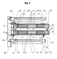
- the four-high rolling mill stand 1 according to FIG. 1 is not by two roller stand shown formed in which in not shown chocks a lower and an upper Work roll 2, 3 and a lower and an upper backup roll 4, 5 are rotatably mounted.
- Roll cooling and / or lubrication device for the work rolls 2, 3 and the support rollers 4, 5 each consist of a nozzle bar 7, 8 for the work rolls 2, 3 and a nozzle bar 9, 10 for each the support rollers 4, 5.
- nozzle bars 7-10 are across the width of the rollers Spray nozzles 11 with upstream, as solenoid valves trained control valves 12 for applying cooling oil and / or emulsions installed on the rollers 2-5.
- the the Backing rolls 3, 4 assigned to the nozzle bars 9, 10 are stationary, while the nozzle bars 7, 8 assigned to the work rolls 2, 3 in the direction of arrow b, c in the direction of its longitudinal axis 13-13 transversely to the tape running direction a over the bandwidth and around their longitudinal axis 13-13 are pivotable.
- the respective supply of rolling oil and / or emulsions the adjustable nozzle bar 7, 8 and the stationary Nozzle bar 9, 10 becomes pressure and / or quantity and / or temperature controlled.
- nozzle bars 7, 8 At the two ends 15, 16 of the work rolls 2, 3 assigned two nozzle bars 7, 8 are adapters 17 rotatable and displaceable mounting of the nozzle bars around and in Direction of the longitudinal axis 13-13 on two hollow journals 18, 19 attached, in side plates 20, 21 on the two Roller stands, not shown, of the four-high rolling mill stand 1 are installed, the supply of the coolant or Emulsions to the spray nozzles installed in the nozzle bars 7, 8 11 and the associated control valves 12 through a feed line 22 in a side plate 20, the cavity 23 of the in Side plate 20 built-in bearing pin 18, the interior 24 of the adapter 17 seated on the journal 18 and the Distribution channel 25 of the nozzle bars 7, 8 takes place.
- the supply of the coolant to the nozzle bars 7, 8 can also by a feed line 22 in each of the two side plates 20, 21, in these built-in hollow journals 18, 19, the on this seated adapter 17 and the distribution channel 25 of the Nozzle bars are made.
- the connecting cables for the control valves 12 of the spray nozzles 11 the nozzle bars 7, 8 are in several flexible protective tubes 30 merged, the length of the connecting cable Control valves is dimensioned such that a pivoting of the Nozzle bar 7, 8 around the bar longitudinal axis 13-13 is possible.
- Temperature sensor 31 for detecting the size of the thermal Roll bales outside the maximum range and in Roll center by measuring the temperature of the roll surface integrated to adjust the roll gap model.
- Deviating from the above-described embodiment of the new roller cooling and lubrication device Possibility of an additional movability and a Pivotal movement of the nozzle bars 9, 10 for the support rollers 4, 5 in the direction of or around the longitudinal axis of the beam to provide.
- the nozzle bars 7, 8 can be moved for the work rolls 2, 3 and the nozzle bar 9, 10 for the Back-up rolls 4, 5 together or independently or only a movability of the nozzle bars 7, 8 for the Work rolls 2, 3 from a maintenance position remote from the roll in the working position and from the working position to the Maintenance position should be considered.
Landscapes
- Engineering & Computer Science (AREA)
- Mechanical Engineering (AREA)
- Metal Rolling (AREA)
- Control Of Metal Rolling (AREA)
Abstract
Description
Die Erfindung betrifft eine Walzenkühl- und/oder Schmiervorrichtung für Kaltbandwalzwerke, insbesondere Feinband- und Folienwalzwerke, mit den einzelnen Walzen zugeordneten, an den Seitenschildern der Walzenständern eines oder mehrerer Walzgerüste angebrachten Düsenbalken, in die über die Breite der Walzen Sprühdüsen eingebaut und die relativ zu den ihnen zugeordneten Walzen unabhängig voneinander quer zur Laufrichtung des Walzbandes in zur Bandebene parallelen Ebenen verstellbar sind, zur Regelung der Bandzugspannung über die Bandbreite durch eine Änderung des wirksamen Walzenballendurchmessers und/oder eine Beeinflussung der Walzenschmierung mit einer druck- und/oder mengen- und/oder temperaturgeregelten Zuführung von Walzöl oder Emulsionen.The invention relates to a roller cooling and / or Lubrication device for cold strip rolling mills, especially fine strip and film rolling mills, assigned to the individual rolls the side plates of the roller stands of one or more Rolling stands attached to the nozzle bars into which the width of the Roller spray nozzles built in and relative to them assigned rollers independently of one another transversely to the direction of travel of the rolled strip can be adjusted in planes parallel to the strip plane are used to regulate the belt tension over the bandwidth a change in the effective roll bale diameter and / or influencing the roller lubrication with a pressure and / or quantity and / or temperature controlled supply of Rolling oil or emulsions.
Die Planheitsregelung des Walzbandes bei einem Kaltbandwalzwerk, das mit einer aus der DE 34 19 261 C3 bekannten Walzenkühl- und/oder Schmiervorrichtung der gattungsgemäßen Art ausgerüstet ist, beruht auf einer Änderung des Sprühbildes des auf die Oberfläche der Arbeitswalzen aufgesprühten Walzöls oder von aufgesprühten Emulsionen. Die Änderung des Sprühbildes wird durch eine Verstellung des jeder Arbeitswalze des Walzwerks zugeordneten Düsenbalkens relativ zur Arbeitswalze unabhängig vom jeweils anderen Düsenbalken quer zur Bandlaufrichtung in einer zur Bandebene parallelen Ebene und eine druck- und/oder mengen- und/oder temperaturgeregelte Zuführung von Walzöl oder Emulsionen bewirkt. The flatness control of the rolled strip at one Cold strip rolling mill, which with a from DE 34 19 261 C3 known roller cooling and / or lubricating device generic type is based on a change of the spray pattern on the surface of the work rolls sprayed rolling oil or sprayed emulsions. The The spray pattern is changed by adjusting each Work roll of the rolling mill associated nozzle bar relative to Work roll independent of the other nozzle bar across Belt running direction in a plane parallel to the belt plane and a pressure and / or quantity and / or temperature controlled Supply of rolling oil or emulsions causes.
Fein- und Folienband, das auf einem mit der bekannten Planheitsregelung ausgerüsteten Quarto- oder Sextowalzgerüst gewalzt wird, zeichnet sich durch eine hohe Qualität hinsichtlich Maß- und Formgenauigkeit sowie Planheit aus.Fine and foil tape on a known one Flatness control equipped quarto or sexto roll stand rolled is characterized by high quality with regard to dimensional and shape accuracy as well as flatness.
Nachteilig bei Walzenkühl- und/oder Schmiervorrichtungen der gattungsgemäßen Art für Kaltbandwalzwerke ist die unzureichende Zugängigkeit der Düsenbalken mit den Sprühdüsen und den zugehörigen Steuerventilen, so daß Reparatur- und Wartungsarbeiten an den Düsenbalken umständlich und zeitaufwendig sind.A disadvantage of roller cooling and / or lubricating devices The generic type for cold strip rolling mills is the insufficient one Accessibility of the nozzle bars with the spray nozzles and the associated control valves, so that repair and Maintenance work on the nozzle bars cumbersome and are time consuming.
Die in der DE 94 18 359.7 U1 beschriebene Konstruktion einer Walzenkühl- und/oder Schmiervorrichtung für Kaltbandwalzwerke mit bandeinlaufseitig an den beiden Walzenständern eines Walzgerüstes angeordneten, in vertikaler Richtung verfahrbaren Hubbalken sowie auf diesen in horizontaler Richtung verfahrbaren Schlitten mit Tragarmen für die Düsenbalken zum Verfahren derselben aus einer walzenfernen Wartungsposition in die Arbeitsposition an die Walzen und aus der Arbeitsposition in die Wartungsposition ist technisch aufwendig.The construction described in DE 94 18 359.7 U1 Roll cooling and / or lubrication device for cold strip rolling mills with one on the roll infeed side on the two roll stands Roll stand arranged, movable in the vertical direction Walking beam and movable on it in the horizontal direction Carriage with support arms for the nozzle bars for moving the same from a maintenance position remote from the roller into the Working position on the rollers and from the working position in the Maintenance position is technically complex.
Der Erfindung liegt die Aufgabe zugrunde, die Regelung der Bandplanheit bei Kaltbandwalzwerken mittels der gattungsgemäßen Walzenkühl- und/oder Schmiervorrichtung zu optimieren, um unerwünschte Bandzugspannungsabweichungen zonenweise im gewalzten Band auszuregeln, und die Zugängigkeit der in die Düsenbalken der Walzenkühl- und/oder Schmiervorrichtung eingebauten Sprühdüsen und deren zugehörigen Steuerventile im Hinblick auf eine Vereinfachung und eine Beschleunigung von notwendigen Reparatur- und Wartungsarbeiten zu verbessern. The invention has for its object the regulation of Strip flatness in cold strip rolling mills using the generic type Roll cooling and / or lubricating device to optimize unwanted strip tension deviations in zones leveled rolled strip, and the accessibility of the in the Nozzle bar of the roller cooling and / or lubricating device built-in spray nozzles and their associated control valves in the With a view to simplification and acceleration of to improve necessary repair and maintenance work.
Diese Aufgabe ist erfindungsgemäß gelöst durch eine Walzenkühl- und/oder Schmiervorrichtung für Kaltbandwalzwerke mit den Merkmalen des Patentanspruchs 1.This object is achieved by a Roll cooling and / or lubrication device for cold strip rolling mills with the features of claim 1.
Die Unteransprüche beinhalten vorteilhafte und zweckmäßige Weiterbildungen der Erfindung.The sub-claims contain advantageous and expedient Developments of the invention.
Der Ansprühwinkel der Sprühdüsen der Düsenbalken mit Bezug auf die Walzen, der bei der erfindungsgemäßen Walzenkühl- und/oder Schmiervorrichtung durch Schwenken der Düsenbalken um die Balkenlängsachse einstellbar ist, stellt eine weitere Stellgröße zusätzlich zu der Verstellbarkeit der Düsenbalken relativ zu der jeweils zugeordneten Walze quer zur Bandlaufrichtung sowie der Veränderung der Menge, des Drucks und der Temperatur des auf die Walzen aufgesprühten Walzöls oder der aufgesprühten Emulsionen zur Änderung des Sprühbildes auf der Walzenoberfläche im Rahmen einer Bandplanheitsregelung dar. Der Ansprühwinkel der Spühdüsen als zusätzliche Stellgröße ermöglicht eine Optimierung der Bandplanheitsregelung. Durch ein Schwenken der Düsenbalken um 180° können die Sprühdüsen auf einfache Weise aus der walzennahen Betriebsposition in eine walzenabgewandte Wartungsposition zur einfachen und schnellen Durchführung von erforderlichen Wartungs- und Reparaturarbeiten gebracht werden.The spray angle of the spray nozzles of the nozzle bars with reference on the rolls, which in the roll cooling and / or lubrication device by pivoting the nozzle bar the longitudinal axis of the bar is adjustable, represents another Command value in addition to the adjustability of the nozzle bar relative to the respective assigned roller across Direction of tape travel as well as the change in quantity, pressure and the temperature of the rolling oil sprayed onto the rolls or the sprayed emulsions to change the spray pattern on the Roll surface in the context of a strip flatness control Spray angle of the spray nozzles as an additional manipulated variable enables optimization of the strip flatness control. Through a The spray nozzles can swivel the nozzle bar by 180 ° simple way from the operating position close to the roller into one Maintenance position facing away from the roller for simple and quick Carrying out necessary maintenance and repair work to be brought.
Die Erfindung ist nachstehend anhand schematischer Zeichnungen einer bei einem Quartowalzgerüst eingesetzten Walzenkühl- und Schmiervorrichtung erläutert, wobei die Zeichnungsfiguren folgendes darstellen:
- Fig. 1
- eine perspektivische Darstellung eines Quartowalzgerüstes mit Düsenbalken zum Kühlen und Schmieren der Arbeitswalzen und der Stützwalzen,
- Fig. 2
- eine Vorderansicht der Düsenbalken nach Fig. 1,
- Fig. 3
- eine Schnittdarstellung einer Dreh- und Schiebelagerung eines Endes eines in der Betriebsposition befindlichen Düsenbalkens und
- Fig. 4
- eine Schnittdarstellung einer Dreh- und Schiebelagerung eines Düsenbalkens in der gegenüber der Darstellung in Fig. 3 um 180° gedrehten Wartungsposition.
- Fig. 1
- a perspective view of a four-high rolling mill with nozzle bars for cooling and lubricating the work rolls and the backup rolls,
- Fig. 2
- 2 shows a front view of the nozzle bar according to FIG. 1,
- Fig. 3
- a sectional view of a rotary and sliding bearing of one end of a nozzle bar in the operating position and
- Fig. 4
- a sectional view of a rotary and sliding bearing of a nozzle bar in the maintenance position rotated by 180 ° compared to the illustration in FIG. 3.
Das Quartowalzgerüst 1 nach Fig. 1 wird durch zwei nicht
dargestellte Walzenständer gebildet, in denen in nicht
dargestellten Einbaustücken eine untere und eine obere
Arbeitswalze 2, 3 sowie eine untere und eine obere Stützwalze 4,
5 drehbar gelagert sind.The four-high rolling mill stand 1 according to FIG. 1 is not by two
roller stand shown formed in which in not
shown chocks a lower and an
Die für die Planheitsregelung des Walzbandes 6 einsetzbare
Walzenkühl- und/oder Schmiervorrichtung für die Arbeitswalzen 2,
3 und die Stützwalzen 4, 5 besteht aus je einem Düsenbalken 7, 8
für die Arbeitswalzen 2, 3 und je einem Düsenbalken 9, 10 für
die Stützwalzen 4, 5.Which can be used for the flatness control of the rolled
In die Düsenbalken 7-10 sind über die Breite der Walzen
Sprühdüsen 11 mit vorgeschalteten, als Elektromagnetventile
ausgebildeten Steuerventilen 12 zum Aufbringen von Kühlöl
und/oder Emulsionen auf die Walzen 2-5 eingebaut. Die den
Stützwalzen 3, 4 zugeordneten Düsenbalken 9, 10 sind stationär,
während die den Arbeitswalzen 2, 3 zugeordneten Düsenbalken 7, 8
in Pfeilrichtung b, c in Richtung ihrer Längsachse 13-13 quer
zur Bandlaufrichtung a über die Bandbreite verfahrbar und um
ihre Längsachse 13-13 schwenkbar sind. In the nozzle bars 7-10 are across the width of the
Die jeweilige Zuführung von Walzöl und/oder Emulsionen zu
den verstellbaren Düsenbalken 7, 8 und den stationären
Düsenbalken 9, 10 wird druck- und/oder mengen- und/oder
temperaturgeregelt.The respective supply of rolling oil and / or emulsions
the
Durch ein Verschieben der Düsenbalken 7, 8 in Richtung der
Balkenlängsachse 13-13 quer zur Laufrichtung a des Walzbandes 6
und durch ein Schwenken der Düsenbalken 7, 8 um die
Balkenlängsachse 13-13 zum Einstellen des Ansprühwinkels der
Sprühdüsen 11 zu den Arbeitswalzen 2, 3 werden die
Sprühzonenbreite der Düsen 11 auf den Arbeitswalzen 2, 3 und das
Sprühbild der Sprühdüsen 11 eingestellt. Die Regelung von Druck,
Temperatur und Menge des den Düsenbalken 7, 8 zugeführten
Walzöls beziehungsweise der zugeführten Emulsionen beeinflußt
die Kühlung der Arbeitswalzen 2, 3 und damit die Größe und die
Schnelligkeit der Änderung des wirksamen
Walzenballendurchmessers und des von diesem abhängigen
Walzspaltes 14 zwischen den Arbeitswalzen 2, 3 beziehungsweise
der Schmierung der Arbeitswalzen.By moving the
Die durch eine nicht dargestellte Planheitsmeßrolle im
Bandauslauf hinter dem Walzensatz gemessenen Werte der
Bandzugspannungsverteilung über die Breite des Walzbandes 6
werden in einem Rechner aufgearbeitet und zur Regelung der
Kühlung und/oder der Schmierung der Arbeitswalzen 2, 3 mittels
der verfahrbaren und schwenkbaren Düsenbalken 7, 8 verwendet.The by a flatness measuring roller, not shown in
Belt outlet behind the roller set measured values of
Strip tension distribution over the width of the rolled
Durch eine genaue Positionierung der in Richtung der
Balkenlängsachse 13-13 quer zur Bandlaufrichtung a verfahrbaren
und um die Balkenlängsachse schwenkbaren Düsenbalken 7, 8 mit
den Sprühdüsen 11 können unerwünschte
Bandzugspannungsabweichungen zonenweise im gewalzten Band 6
ausgeregelt und dadurch ein planes Bandes erzeugt werden.By accurately positioning the towards the
Beam longitudinal axis 13-13 can be moved transversely to the strip running direction a
and with the
An den beiden Enden 15, 16 der den Arbeitswalzen 2, 3
zugeordneten beiden Düsenbalken 7, 8 sind Adapter 17 zur
drehbaren und verschiebbaren Lagerung der Düsenbalken um und in
Richtung der Balkenlängsachse 13-13 auf zwei hohlen Lagerzapfen
18, 19 angebracht, die in Seitenschilder 20, 21 an den beiden
nicht dargestellten Walzenständern des Quartowalzgerüstes 1
eingebaut sind, wobei die Zuführung des Kühlmittels bzw. der
Emulsionen zu den in den Düsenbalken 7, 8 eingebauten Sprühdüsen
11 und den zugehörigen Steuerventilen 12 durch eine Zuleitung 22
in einem Seitenschild 20, den Hohlraum 23 des in das
Seitenschild 20 eingebauten Lagerzapfens 18, den Innenraum 24
des auf dem Lagerzapfen 18 sitzenden Adapters 17 und den
Verteilerkanal 25 der Düsenbalken 7, 8 erfolgt.At the two
Die Zuführung des Kühlmittels zu den Düsenbalken 7, 8 kann
auch durch jeweils eine Zuleitung 22 in beiden Seitenschildern
20, 21, die in diese eingebauten hohlen Lagerzapfen 18, 19, die
auf diesen sitzenden Adapter 17 und den Verteilerkanal 25 der
Düsenbalken erfolgen.The supply of the coolant to the
Auf den beiden Lagerzapfen 18, 19 der Düsenbalken 7, 8 sind
hydraulische Stellzylinder 26, 27 mit an den Adaptern 17
angreifenden Stellkolben 28 zum Verschieben der Düsenbalken 7, 8
in Pfeilrichtung b, c quer zur Laufrichtung a des Walzbandes 6
angeordnet.On the two
An die beiden Seitenschilde 20, 21 ist je ein an einem
Adapter 17 angreifender Drehantrieb 29 zum Schwenken der
Düsenbalken 7, 8 um ihre Längsachse 13-13 angebaut. On the two
Die Anschlußkabel für die Steuerventile 12 der Sprühdüsen 11
der Düsenbalken 7, 8 sind in mehreren flexiblen Schutzschläuchen
30 zusammengeführt, wobei die Länge der Anschlußkabel der
Steuerventile derart bemessen ist, daß ein Schwenken der
Düsenbalken 7, 8 um die Balkenlängsachse 13-13 möglich ist.The connecting cables for the
Bei Reparatur- und Wartungsarbeiten an den Sprühdüsen 11
werden die Düsenbalken 7, 8 aus der Betriebsposition gemäß Fig.
3 um 180° in die Wartungsposition gemäß Fig. 4 geschwenkt, in
der die den Arbeitswalzen 2, 3 abgewandten Sprühdüsen 11 frei
zugängig sind. Wartungs- und Reparaturarbeiten an den
Steuerventilen 12 der Düsenbalken 7, 8 werden zweckmäßig in der
Betriebsposition der Düsenbalken gemäß Fig. 3 durchgeführt.During repair and maintenance work on the
In die Düsenbalken 7, 8 für die Arbeitswalzen 2, 3 sind
Temperaturfühler 31 zur Erfassung der Größe des thermischen
Walzenballens außerhalb der maximalen Bandbreite und in
Walzenmitte durch eine Temperaturmessung der Walzenoberfläche
zum Abgleich des Walzspaltmodells integriert.In the
Abweichend von der vorbeschriebenen Ausführungsform der
neuen Walzenkühl- und Schmiervorrichtung besteht die
Möglichkeit, zusätzlich eine Verschiebbarkeit und eine
Verschwenkbarkeit der Düsenbalken 9, 10 für die Stützwalzen 4, 5
in Richtung der beziehungsweise um die Balkenlängsachse
vorzusehen. Ferner kann eine Verfahrbarkeit der Düsenbalken 7, 8
für die Arbeitswalzen 2, 3 und der Düsenbalken 9, 10 für die
Stützwalzen 4, 5 zusammen oder unabhängig voneinander oder
lediglich eine Verfahrbarkeit der Düsenbalken 7, 8 für die
Arbeitswalzen 2, 3 aus einer walzenfernen Wartungsposition in
die Arbeitsposition und aus der Arbeitsposition in die
Wartungsposition in Betracht gezogen werden. Deviating from the above-described embodiment of the
the new roller cooling and lubrication device
Possibility of an additional movability and a
Pivotal movement of the
Claims (6)
Applications Claiming Priority (2)
| Application Number | Priority Date | Filing Date | Title |
|---|---|---|---|
| DE10017579 | 2000-04-08 | ||
| DE10017579 | 2000-04-08 |
Publications (3)
| Publication Number | Publication Date |
|---|---|
| EP1142653A2 true EP1142653A2 (en) | 2001-10-10 |
| EP1142653A3 EP1142653A3 (en) | 2004-01-02 |
| EP1142653B1 EP1142653B1 (en) | 2005-02-09 |
Family
ID=7638092
Family Applications (1)
| Application Number | Title | Priority Date | Filing Date |
|---|---|---|---|
| EP01107353A Expired - Lifetime EP1142653B1 (en) | 2000-04-08 | 2001-03-24 | Roll cooling and/or lubricating device for cold strip rolling mills, in particular fine strip and foil rolling mills |
Country Status (4)
| Country | Link |
|---|---|
| US (1) | US6598448B1 (en) |
| EP (1) | EP1142653B1 (en) |
| JP (1) | JP2001347305A (en) |
| DE (2) | DE10043281B4 (en) |
Cited By (9)
| Publication number | Priority date | Publication date | Assignee | Title |
|---|---|---|---|---|
| EP1775039A1 (en) * | 2005-10-14 | 2007-04-18 | ACHENBACH BUSCHHÜTTEN GmbH | Spray nozzle valve for mounting in a nozzle bar |
| CN101683660B (en) * | 2008-09-28 | 2011-07-20 | 宝山钢铁股份有限公司 | Control method of tandem cold rolling mill emulsion section cooling |
| WO2011134216A1 (en) * | 2010-04-27 | 2011-11-03 | 中冶南方工程技术有限公司 | Blocking method for emulsion side channeling |
| WO2011134219A1 (en) * | 2010-04-27 | 2011-11-03 | 中冶南方工程技术有限公司 | Emulsion side channeling blocking device |
| CN102974617A (en) * | 2012-12-05 | 2013-03-20 | 江苏永钢集团有限公司 | Roller cooler transverse positioning device |
| CN104105554A (en) * | 2012-02-15 | 2014-10-15 | 西门子Vai金属科技有限责任公司 | Low maintenance nozzle mixer unit for roll nip lubrication |
| EP3251762A1 (en) | 2016-06-02 | 2017-12-06 | Primetals Technologies Austria GmbH | Lubricating device for applying a lubricant when rolling a product to be rolled |
| CN111589863A (en) * | 2020-05-28 | 2020-08-28 | 天津市宇润德金属制品有限公司 | Be used for steel sheet to press thin processing system |
| CN114535300A (en) * | 2016-10-17 | 2022-05-27 | 首要金属科技奥地利有限责任公司 | Cooling of rolls of a rolling stand |
Families Citing this family (17)
| Publication number | Priority date | Publication date | Assignee | Title |
|---|---|---|---|---|
| DE10352546A1 (en) * | 2003-09-04 | 2005-03-31 | Sms Demag Ag | Method and device for applying an adjustable tensile stress distribution, in particular in the edge regions of cold-rolled metal strips |
| DE102005042020A1 (en) * | 2005-09-02 | 2007-03-08 | Sms Demag Ag | Method for lubricating and cooling rolls and metal strip during rolling, in particular during cold rolling, of metal strips |
| CH702087A1 (en) * | 2009-10-20 | 2011-04-29 | Bba Innova Ag | Roll cooling apparatus. |
| CN101829681A (en) * | 2010-04-27 | 2010-09-15 | 中冶南方工程技术有限公司 | Intermediate roll-scurrying vacancy emulsion channeling blocking device |
| CN101837370B (en) * | 2010-04-27 | 2012-05-02 | 中冶南方工程技术有限公司 | Method for blocking emulsion fluid channeling from middle roll shifting vacant site |
| CN102049417B (en) * | 2010-11-04 | 2012-11-14 | 山东钢铁股份有限公司 | Combined adjustable type rolling machine roll collar cooling device |
| EP2676744A1 (en) * | 2012-06-22 | 2013-12-25 | Siemens VAI Metals Technologies GmbH | Device for sprinkling a rolling plant and method for extracting/inserting said system from/in said rolling cage |
| CN102861773B (en) * | 2012-09-25 | 2015-06-17 | 宝鸡凸鹏金属材料有限责任公司 | Lubricating method for rolling titanium precision thin strips |
| US20160101451A1 (en) * | 2014-10-09 | 2016-04-14 | Josef Froehling Gmbh & Co. Kg | Rolling Device and Rolling Process |
| CN105478497A (en) * | 2015-12-08 | 2016-04-13 | 无锡华工薄板有限公司 | Rotating washing device for cold-rolled band steel |
| CN105798071B (en) * | 2016-05-26 | 2018-03-13 | 中冶南方工程技术有限公司 | Shape rolling mill on-line cooling device |
| CN111633043A (en) * | 2020-07-07 | 2020-09-08 | 北京鑫山重工技术有限责任公司 | Reinforcing steel bar lubricating device |
| IT202100005663A1 (en) * | 2021-03-10 | 2022-09-10 | Danieli Off Mecc | PROCESS AND PLANT FOR THE PRODUCTION OF FLAT LAMINATED PRODUCTS |
| CN114042768A (en) * | 2021-10-08 | 2022-02-15 | 中冶南方工程技术有限公司 | Strip steel oil removing method, strip steel oil removing device and rolling mill |
| CN114054510B (en) * | 2021-11-05 | 2022-11-15 | 燕山大学 | Near-isothermal heatable roller with roller end heat dissipation function and control method thereof |
| CN114798723B (en) * | 2022-04-28 | 2024-08-02 | 青岛中兴源模具有限公司 | Cold rolling die |
| CN115488168B (en) * | 2022-09-26 | 2023-06-20 | 马鞍山延隆新材料科技有限公司 | Lubricating and cooling device for producing high-rolling-capacity high-ductility cold-rolled ribbed steel bars |
Citations (7)
| Publication number | Priority date | Publication date | Assignee | Title |
|---|---|---|---|---|
| DE3419261A1 (en) * | 1984-05-23 | 1985-11-28 | Achenbach Buschhütten GmbH, 5910 Kreuztal | DEVICE FOR DETECTING AND REGULATING THE PLANNESS OF BAND-SHAPED ROLLING MATERIAL, IN PARTICULAR FINE-BANDING, FOR COLD ROLLING MILLS |
| GB2207373A (en) * | 1985-10-11 | 1989-02-01 | Joseph Donald Svatos | Rolling mill coolant system |
| EP0374538A2 (en) * | 1988-12-05 | 1990-06-27 | Norandal Usa, Inc. | Spray system for rolling mill |
| EP0542640A1 (en) * | 1991-10-24 | 1993-05-19 | United Engineering, Inc. | Method and apparatus for cooling rolling mill rolls |
| JPH0615315A (en) * | 1992-06-30 | 1994-01-25 | Hitachi Ltd | Heat crown controller for rolling rolls |
| DE9418359U1 (en) * | 1994-11-17 | 1995-01-12 | Achenbach Buschhütten GmbH, 57223 Kreuztal | Roll cooling and / or lubricating device for cold strip rolling mills, especially fine strip rolling mills |
| US5460023A (en) * | 1991-09-13 | 1995-10-24 | International Rolling Mill Consultants Inc. | Roll surface restoration system and method |
Family Cites Families (5)
| Publication number | Priority date | Publication date | Assignee | Title |
|---|---|---|---|---|
| FR2459238A1 (en) * | 1979-06-20 | 1981-01-09 | Rhone Poulenc Agrochimie | PROCESS FOR THE PREPARATION OF BENZOXAZOLONE |
| GB2156255A (en) * | 1984-03-23 | 1985-10-09 | Davy Mckee | Rolling mill |
| EP0205295B1 (en) * | 1985-06-10 | 1990-12-05 | DAVY McKEE (POOLE) LIMITED | Improvements relating to the lubrication of rolling mills |
| US4706480A (en) * | 1985-10-11 | 1987-11-17 | Svatos Joseph D | Rolling mill cooling system |
| US5524465A (en) * | 1991-03-29 | 1996-06-11 | Hitachi, Ltd. | Work rolls crossing type mill, rolling system and rolling method |
-
2000
- 2000-09-02 DE DE10043281A patent/DE10043281B4/en not_active Expired - Fee Related
-
2001
- 2001-03-24 EP EP01107353A patent/EP1142653B1/en not_active Expired - Lifetime
- 2001-03-24 DE DE50105274T patent/DE50105274D1/en not_active Expired - Lifetime
- 2001-04-05 JP JP2001107111A patent/JP2001347305A/en not_active Withdrawn
- 2001-04-06 US US09/827,705 patent/US6598448B1/en not_active Expired - Fee Related
Patent Citations (7)
| Publication number | Priority date | Publication date | Assignee | Title |
|---|---|---|---|---|
| DE3419261A1 (en) * | 1984-05-23 | 1985-11-28 | Achenbach Buschhütten GmbH, 5910 Kreuztal | DEVICE FOR DETECTING AND REGULATING THE PLANNESS OF BAND-SHAPED ROLLING MATERIAL, IN PARTICULAR FINE-BANDING, FOR COLD ROLLING MILLS |
| GB2207373A (en) * | 1985-10-11 | 1989-02-01 | Joseph Donald Svatos | Rolling mill coolant system |
| EP0374538A2 (en) * | 1988-12-05 | 1990-06-27 | Norandal Usa, Inc. | Spray system for rolling mill |
| US5460023A (en) * | 1991-09-13 | 1995-10-24 | International Rolling Mill Consultants Inc. | Roll surface restoration system and method |
| EP0542640A1 (en) * | 1991-10-24 | 1993-05-19 | United Engineering, Inc. | Method and apparatus for cooling rolling mill rolls |
| JPH0615315A (en) * | 1992-06-30 | 1994-01-25 | Hitachi Ltd | Heat crown controller for rolling rolls |
| DE9418359U1 (en) * | 1994-11-17 | 1995-01-12 | Achenbach Buschhütten GmbH, 57223 Kreuztal | Roll cooling and / or lubricating device for cold strip rolling mills, especially fine strip rolling mills |
Non-Patent Citations (1)
| Title |
|---|
| PATENT ABSTRACTS OF JAPAN vol. 018, no. 217 (M-1594), 19. April 1994 (1994-04-19) -& JP 06 015315 A (HITACHI LTD;OTHERS: 01), 25. Januar 1994 (1994-01-25) * |
Cited By (12)
| Publication number | Priority date | Publication date | Assignee | Title |
|---|---|---|---|---|
| EP1775039A1 (en) * | 2005-10-14 | 2007-04-18 | ACHENBACH BUSCHHÜTTEN GmbH | Spray nozzle valve for mounting in a nozzle bar |
| CN101683660B (en) * | 2008-09-28 | 2011-07-20 | 宝山钢铁股份有限公司 | Control method of tandem cold rolling mill emulsion section cooling |
| WO2011134216A1 (en) * | 2010-04-27 | 2011-11-03 | 中冶南方工程技术有限公司 | Blocking method for emulsion side channeling |
| WO2011134219A1 (en) * | 2010-04-27 | 2011-11-03 | 中冶南方工程技术有限公司 | Emulsion side channeling blocking device |
| CN104105554A (en) * | 2012-02-15 | 2014-10-15 | 西门子Vai金属科技有限责任公司 | Low maintenance nozzle mixer unit for roll nip lubrication |
| US9566623B2 (en) | 2012-02-15 | 2017-02-14 | Primetals Technologies Austria GmbH | Low maintenance nozzle mixer unit for roll nip lubrication |
| CN102974617A (en) * | 2012-12-05 | 2013-03-20 | 江苏永钢集团有限公司 | Roller cooler transverse positioning device |
| EP3251762A1 (en) | 2016-06-02 | 2017-12-06 | Primetals Technologies Austria GmbH | Lubricating device for applying a lubricant when rolling a product to be rolled |
| WO2017207622A1 (en) | 2016-06-02 | 2017-12-07 | Primetals Technologies Austria GmbH | Lubrication device for applying a lubricant when rolling a rolling material |
| US11440067B2 (en) | 2016-06-02 | 2022-09-13 | Primetals Technologies Austria GmbH | Lubricating device for applying a lubricant when rolling a rolling material |
| CN114535300A (en) * | 2016-10-17 | 2022-05-27 | 首要金属科技奥地利有限责任公司 | Cooling of rolls of a rolling stand |
| CN111589863A (en) * | 2020-05-28 | 2020-08-28 | 天津市宇润德金属制品有限公司 | Be used for steel sheet to press thin processing system |
Also Published As
| Publication number | Publication date |
|---|---|
| US6598448B1 (en) | 2003-07-29 |
| EP1142653B1 (en) | 2005-02-09 |
| DE10043281B4 (en) | 2004-04-15 |
| EP1142653A3 (en) | 2004-01-02 |
| DE10043281A1 (en) | 2001-10-18 |
| JP2001347305A (en) | 2001-12-18 |
| DE50105274D1 (en) | 2005-03-17 |
Similar Documents
| Publication | Publication Date | Title |
|---|---|---|
| DE10043281B4 (en) | Roller cooling and / or lubricating device for cold strip rolling mills, especially fine strip and foil rolling mills | |
| EP1142652B1 (en) | Cold strip rolling mill, in particular fine strip and foil rolling mill, with a roll cooling and/or lubricating device for cold strip rolling mills, in particular fine strip and foil rolling mills | |
| EP2403663B1 (en) | Method and cooling device for cooling the rollers of a roll stand | |
| DE3419261C3 (en) | Roll cooling and / or lubricating device for cold strip rolling mills, especially fine strip rolling mills | |
| EP2846940B1 (en) | Device for cooling rolls | |
| DE68912671T2 (en) | Double-strip continuous casting machine with guide and cooling for the casting product for high-speed casting of products with a liquid core. | |
| DE3616070A1 (en) | ROLLER COOLING DEVICE AND METHOD | |
| WO2010034481A2 (en) | Rolling apparatus | |
| EP3150291B1 (en) | Method and device for cooling a roller which is arranged in a rolling stand | |
| DE19524729A1 (en) | Method and device for rolling strips with a non-uniform thickness and / or length distribution across their width | |
| DE3507846C1 (en) | Device for greasing workpieces during forming and during rolling, in particular a roller conveyor lubricator | |
| DE2505324A1 (en) | ROLLED MATERIAL CLAMPING DEVICE FOR A ROLLING MILL | |
| EP1827735A1 (en) | Method and device for continuous casting of metals | |
| DE3047496A1 (en) | "METHOD AND DEVICE FOR CONTINUOUSLY SMOOTHING AND EVENLY COOLING A BALE OF A ROLLING CYLINDER ARRANGED IN A RELATED WORKING DEVICE" | |
| EP0058869B1 (en) | Guiding support stand in the driving and/or straightening range of a continuous casting plant | |
| DE3607527A1 (en) | DEVICE FOR REGULATING THE PLANNESS AND THICKNESS OF ROLLING STRIP IN A MULTI-ROLLING ROLLING DEVICE | |
| DE19905833C2 (en) | Device for introducing lubricant into the roll gap of a hot rolling mill | |
| EP3515615B1 (en) | Roll treatment during operation | |
| DE9418359U1 (en) | Roll cooling and / or lubricating device for cold strip rolling mills, especially fine strip rolling mills | |
| EP3453466A1 (en) | Rolling mill for rolling a metallic product and method for operating a rolling mill | |
| DE10117096B4 (en) | Device for untwisting rolled billets | |
| DE102022204686A1 (en) | Two-roller casting device for producing a cast metal strip, and method for cooling and/or cleaning an outer surface of a casting roll of a two-roller casting device | |
| DE3523483A1 (en) | ROLLER COOLING AND / OR LUBRICATION DEVICE FOR COLD-TAPE ROLLING MILLS, IN PARTICULAR FINE-TAPE ROLLING MILLS | |
| DE4107205A1 (en) | Rolled steel cooling and hydraulic transport appts. - has inlet funnel connected to upper and lower nozzle heads and symmetrical T-profiles which form compact cooling tube unit | |
| DE102016006401A1 (en) | Scraper device for a multi-roll rolling mill |
Legal Events
| Date | Code | Title | Description |
|---|---|---|---|
| PUAI | Public reference made under article 153(3) epc to a published international application that has entered the european phase |
Free format text: ORIGINAL CODE: 0009012 |
|
| AK | Designated contracting states |
Kind code of ref document: A2 Designated state(s): AT BE CH CY DE DK ES FI FR GB GR IE IT LI LU MC NL PT SE TR |
|
| AX | Request for extension of the european patent |
Free format text: AL;LT;LV;MK;RO;SI |
|
| PUAL | Search report despatched |
Free format text: ORIGINAL CODE: 0009013 |
|
| AK | Designated contracting states |
Kind code of ref document: A3 Designated state(s): AT BE CH CY DE DK ES FI FR GB GR IE IT LI LU MC NL PT SE TR |
|
| AX | Request for extension of the european patent |
Extension state: AL LT LV MK RO SI |
|
| 17P | Request for examination filed |
Effective date: 20040325 |
|
| GRAP | Despatch of communication of intention to grant a patent |
Free format text: ORIGINAL CODE: EPIDOSNIGR1 |
|
| AKX | Designation fees paid |
Designated state(s): DE FR GB IT |
|
| GRAS | Grant fee paid |
Free format text: ORIGINAL CODE: EPIDOSNIGR3 |
|
| GRAA | (expected) grant |
Free format text: ORIGINAL CODE: 0009210 |
|
| AK | Designated contracting states |
Kind code of ref document: B1 Designated state(s): DE FR GB IT |
|
| REG | Reference to a national code |
Ref country code: GB Ref legal event code: FG4D Free format text: NOT ENGLISH |
|
| GBT | Gb: translation of ep patent filed (gb section 77(6)(a)/1977) |
Effective date: 20050209 |
|
| REG | Reference to a national code |
Ref country code: IE Ref legal event code: FG4D Free format text: GERMAN |
|
| REF | Corresponds to: |
Ref document number: 50105274 Country of ref document: DE Date of ref document: 20050317 Kind code of ref document: P |
|
| PLBE | No opposition filed within time limit |
Free format text: ORIGINAL CODE: 0009261 |
|
| STAA | Information on the status of an ep patent application or granted ep patent |
Free format text: STATUS: NO OPPOSITION FILED WITHIN TIME LIMIT |
|
| ET | Fr: translation filed | ||
| 26N | No opposition filed |
Effective date: 20051110 |
|
| PGFP | Annual fee paid to national office [announced via postgrant information from national office to epo] |
Ref country code: FR Payment date: 20110401 Year of fee payment: 11 |
|
| PGFP | Annual fee paid to national office [announced via postgrant information from national office to epo] |
Ref country code: GB Payment date: 20110324 Year of fee payment: 11 |
|
| PGFP | Annual fee paid to national office [announced via postgrant information from national office to epo] |
Ref country code: IT Payment date: 20110331 Year of fee payment: 11 Ref country code: DE Payment date: 20110524 Year of fee payment: 11 |
|
| GBPC | Gb: european patent ceased through non-payment of renewal fee |
Effective date: 20120324 |
|
| REG | Reference to a national code |
Ref country code: FR Ref legal event code: ST Effective date: 20121130 |
|
| REG | Reference to a national code |
Ref country code: DE Ref legal event code: R119 Ref document number: 50105274 Country of ref document: DE Effective date: 20121002 |
|
| PG25 | Lapsed in a contracting state [announced via postgrant information from national office to epo] |
Ref country code: FR Free format text: LAPSE BECAUSE OF NON-PAYMENT OF DUE FEES Effective date: 20120402 Ref country code: GB Free format text: LAPSE BECAUSE OF NON-PAYMENT OF DUE FEES Effective date: 20120324 |
|
| PG25 | Lapsed in a contracting state [announced via postgrant information from national office to epo] |
Ref country code: IT Free format text: LAPSE BECAUSE OF NON-PAYMENT OF DUE FEES Effective date: 20120324 |
|
| PG25 | Lapsed in a contracting state [announced via postgrant information from national office to epo] |
Ref country code: DE Free format text: LAPSE BECAUSE OF NON-PAYMENT OF DUE FEES Effective date: 20121002 |