EP1140477B1 - Automated green tire conveyance system - Google Patents
Automated green tire conveyance system Download PDFInfo
- Publication number
- EP1140477B1 EP1140477B1 EP98963973A EP98963973A EP1140477B1 EP 1140477 B1 EP1140477 B1 EP 1140477B1 EP 98963973 A EP98963973 A EP 98963973A EP 98963973 A EP98963973 A EP 98963973A EP 1140477 B1 EP1140477 B1 EP 1140477B1
- Authority
- EP
- European Patent Office
- Prior art keywords
- tire
- press
- green
- elevator
- monorail
- Prior art date
- Legal status (The legal status is an assumption and is not a legal conclusion. Google has not performed a legal analysis and makes no representation as to the accuracy of the status listed.)
- Expired - Lifetime
Links
- 238000000034 method Methods 0.000 claims description 36
- 239000000969 carrier Substances 0.000 claims description 21
- 230000033001 locomotion Effects 0.000 claims description 17
- 238000012546 transfer Methods 0.000 claims description 9
- 238000013519 translation Methods 0.000 claims description 3
- 230000032258 transport Effects 0.000 description 34
- 238000003860 storage Methods 0.000 description 29
- 230000008569 process Effects 0.000 description 19
- 239000000872 buffer Substances 0.000 description 13
- 238000004519 manufacturing process Methods 0.000 description 11
- 239000011324 bead Substances 0.000 description 10
- 229920001971 elastomer Polymers 0.000 description 9
- 238000000465 moulding Methods 0.000 description 8
- 230000007246 mechanism Effects 0.000 description 6
- 241000282414 Homo sapiens Species 0.000 description 5
- 230000002787 reinforcement Effects 0.000 description 4
- 238000013461 design Methods 0.000 description 3
- 230000008901 benefit Effects 0.000 description 2
- 238000004891 communication Methods 0.000 description 2
- 150000001875 compounds Chemical class 0.000 description 2
- 239000000470 constituent Substances 0.000 description 2
- 238000010276 construction Methods 0.000 description 2
- 238000004132 cross linking Methods 0.000 description 2
- 238000003780 insertion Methods 0.000 description 2
- 230000037431 insertion Effects 0.000 description 2
- 238000012423 maintenance Methods 0.000 description 2
- 239000000463 material Substances 0.000 description 2
- 238000012986 modification Methods 0.000 description 2
- 230000004048 modification Effects 0.000 description 2
- 229920000642 polymer Polymers 0.000 description 2
- 238000012545 processing Methods 0.000 description 2
- 241000254043 Melolonthinae Species 0.000 description 1
- 230000005540 biological transmission Effects 0.000 description 1
- 230000015572 biosynthetic process Effects 0.000 description 1
- 238000010586 diagram Methods 0.000 description 1
- 239000000806 elastomer Substances 0.000 description 1
- 239000004744 fabric Substances 0.000 description 1
- 239000000835 fiber Substances 0.000 description 1
- 239000000945 filler Substances 0.000 description 1
- 238000009434 installation Methods 0.000 description 1
- 238000012432 intermediate storage Methods 0.000 description 1
- 238000007726 management method Methods 0.000 description 1
- 230000037361 pathway Effects 0.000 description 1
- 210000000006 pectoral fin Anatomy 0.000 description 1
- 238000003672 processing method Methods 0.000 description 1
- 239000012536 storage buffer Substances 0.000 description 1
- 239000000126 substance Substances 0.000 description 1
Images


Classifications
-
- B—PERFORMING OPERATIONS; TRANSPORTING
- B29—WORKING OF PLASTICS; WORKING OF SUBSTANCES IN A PLASTIC STATE IN GENERAL
- B29D—PRODUCING PARTICULAR ARTICLES FROM PLASTICS OR FROM SUBSTANCES IN A PLASTIC STATE
- B29D30/00—Producing pneumatic or solid tyres or parts thereof
- B29D30/005—General arrangement or lay-out of plants for the processing of tyres or parts thereof
-
- B—PERFORMING OPERATIONS; TRANSPORTING
- B65—CONVEYING; PACKING; STORING; HANDLING THIN OR FILAMENTARY MATERIAL
- B65G—TRANSPORT OR STORAGE DEVICES, e.g. CONVEYORS FOR LOADING OR TIPPING, SHOP CONVEYOR SYSTEMS OR PNEUMATIC TUBE CONVEYORS
- B65G47/00—Article or material-handling devices associated with conveyors; Methods employing such devices
- B65G47/52—Devices for transferring articles or materials between conveyors i.e. discharging or feeding devices
- B65G47/60—Devices for transferring articles or materials between conveyors i.e. discharging or feeding devices to or from conveyors of the suspended, e.g. trolley, type
- B65G47/61—Devices for transferring articles or materials between conveyors i.e. discharging or feeding devices to or from conveyors of the suspended, e.g. trolley, type for articles
-
- B—PERFORMING OPERATIONS; TRANSPORTING
- B29—WORKING OF PLASTICS; WORKING OF SUBSTANCES IN A PLASTIC STATE IN GENERAL
- B29D—PRODUCING PARTICULAR ARTICLES FROM PLASTICS OR FROM SUBSTANCES IN A PLASTIC STATE
- B29D30/00—Producing pneumatic or solid tyres or parts thereof
- B29D30/0016—Handling tyres or parts thereof, e.g. supplying, storing, conveying
- B29D2030/0022—Handling green tyres, e.g. transferring or storing between tyre manufacturing steps
Definitions
- the present invention relates to automated monorail conveyance systems for transporting green tires (i.e., unvulcanized tires) within a tire manufacturing factory and more specifically to an elevator system incorporated in the monorail conveyance system for transferring the green tire from a monorail to a tire molding press.
- green tires i.e., unvulcanized tires
- Tire manufacturing factories are arranged into separate areas within which specific tire manufacturing operations take place.
- Two manufacturing steps having major significance in relation to the present invention are the tire assembly process and the tire curing, or vulcanizing process. These two processes take place in separate locations within a manufacturing operation, typically within a single building of the tire building factory.
- tires are assembled in an uncured or unvulcanized state in one part of a factory, and then moved to another part of the factory where they are inserted into heated tire presses wherein the tire is molded under heat and pressure and, in the same process, vulcanized.
- the tire assembly process involves the use of a tire building machine which includes a cylindrical assembly drum upon which such tire components as the inner liner, the cord-reinforced plies, the beads and the sidewalls of the "green carcass” are assembled into a cylindrical shape.
- the green carcass then undergoes an initial "blow up” into a toroidal shape more closely resembling a typical tire.
- the blow-up process typically coincides with the installation upon the green carcass of the belt structure, fabric overlay and tread cap, all of which are typically assembled upon a separate "ring” into which the green carcass is expanded during the blow-up process.
- the green tire After the green tire has been assembled, it must be moved to the portion of the tire-manufacturing facility or building wherein the tire is molded and cured.
- the molding and curing are performed in a heated tire molding press in which the external rubber surfaces of the green tire are shaped, as with the tread pattern, under pressure.
- the tire molding press also heats the tire so as to induce the curing or vulcanizing process during which the previously uncured rubber undergoes thermally induced chemical changes that result in the formation of the kinds of firm, stabilized, shape-holding rubber that is typical of a finished tire.
- the two above-described processes are separated in time by the transport of the green tires from the tire assembly area to the location of the curing presses.
- the transport of the green tires involves a layover of the green tires within an intermediate storage area.
- a given green tire is stored until an appropriate press, one that is suited for that specific type of green tire, is ready to receive the tire.
- the tires that are assembled in a typical tire-building process are commonly not all of the same type or size.
- multiple types of tires are assembled in the tire-building region of the factory.
- each different tire type (or size) must be cured in a press that has been set up to receive specific tire types and to shape and cure the specific tire types.
- a multiplicity of considerations come into play in the period of time from when the tire is assembled to when it is cured.
- One consideration is whether or not the tire must be physically transported to the intervening storage area prior to being moved to the curing press.
- Tire transport typically involves the use of such vehicles as fork-lift trucks or similar wheeled vehicles upon which the green tires can be loaded for transport and then unloaded.
- Another consideration is that each different tire type must be accounted for and readily retrievable from within the storage area. That is, each green tire must be easily identifiable so that it can be retrieved from the storage area and then transported to the appropriate tire curing press for insertion into the press as soon as the appropriate press becomes available to receive the green tire.
- the manufacturing facility must be designed to accommodate the wheeled transfer vehicles, that is, it must have wide surfaces "roads" upon which the wheeled vehicles can travel with sufficient room so as to minimize the chances of a collision between the vehicle and stationary objects or with other vehicles or with people.
- the storage area must be large enough to accommodate sufficient numbers of each given type of tire so that at no time, ideally, will any curing press or presses be removed from service for want of a tire in need of molding and curing.
- the storage area also acts as a buffer zone from which a supply of green tires can be withdrawn even if there is a slowdown in the tire assembly process due to disabled machinery or other hold-up problems.
- Tires that are moved from the assembly area to the storage area and then to the curing area are labeled in the assembly area. That is, a tag of some sort is put on the tire, identifying its type, size and other parameters which determine the specific curing press type to which it is to be delivered for final molding and vulcanizing.
- the tag is also placed in such a location on the tire as to indicate the green tire's proper orientation when it is finally delivered to, and loaded into, the curing press. That is to say, the orientation of the tire within the curing press is not random. Rather the tire is preferably placed in the press at a precise rotational orientation determined by numerous factors that are not specifically relevant to the present invention and are therefore not discussed herein.
- Robot arms are used to move the green tires to and from the pallets, which, at the time of loading or unloading, may or may not be situated upon a conveyor vehicle.
- FIGURE 5 in the Nakagawa patent shows a conveyor system that appears to incorporate a monorail, though the term “monorail” is not used per se within the patent.
- the Nakagawa patent addresses centrally located automated control from a site within the factory.
- the '219 patent also refers to the use of a "demand signal," which is not specified as being by wire or radio, as a communication link with the rail-borne “trucks.”
- the apparent monorail trucks of the '219 patent are able to deliver tires directly into the tire presses.
- the Nakagawa patent also includes a buffer storage area located between the tire-building part and the tire press part of the factory.
- One object of the present invention is to provide an automated monorail transport system for automating that part of the tire manufacturing process that involves the transport of tires from the location of green tire assembly to the location of the curing presses where the green tires are molded and vulcanized.
- Another object of the present invention is to provide an automated monorail transport system to minimize the portion of factory floor area that would otherwise be given over to roadways wide enough to safely accommodate both human beings and powered wheeled vehicles.
- Yet another object of the present invention is to provide an automated monorail transport system that maintains a real-time, computer-based accounting of the location in storage or in transport of each green tire according to type and curing press to which it is to be delivered.
- Still another object of the present invention is to provide an automated monorail transport system with automated means by which to rotate each green tire to an optimal angular orientation prior to insertion into the tire molding press.
- Another object of the present invention is to provide an automated monorail transport system that reduces the number of monorail carriers used to transport green tires from the buffer storage to the curing presses.
- Another object of the present invention is to provide an automated monorail transport system that reduces the number of human beings involved in the physical handling, loading and unloading of green tires and to eliminate both the ergonomic problems associated with manual handling of green tires and the potential for manual-induced damage to uncured tires.
- Still another object of the present invention is to provide an automated monorail transport system with automated means for identifying and sorting green tires during transport from the tire assembly area to the tire curing/vulcanizing area of the factory.
- Another object of the present invention is to provide an automated monorail transport system that incorporates multiple tire-storage buffers between the monorail and the tire press.
- a further object of the present invention is to provide an automated monorail transport system that accommodates tire presses of the kind that open vertically.
- Yet another object of the present invention is to provide an automated monorail transport system with central computer management of the automated monorail tire transport system.
- the present invention relates to automated monorail conveyance systems for transporting green tires (i.e., unvulcanized tires) within a tire manufacturing factory. More specifically, the present invention relates to the transport of a plurality of green tires to a plurality of tire curing presses. It includes a monorail track upon which ride one or more monorail transport carriers.
- the conveyance system is characterized by one or more elevator systems located near each of the plurality of the tire presses for receiving green tires from the monorail carriers.
- Each of the elevator systems has an elevator that is vertically moveable for conveying green tires from the monorail carriers to a loader of the tire press.
- the elevator can ride upon a vertical support rail and includes a supporting arm with a basket mounted at the distal end of the arm. In operation, the basket receives a green tire from a monorail truck at a first location and is then moveable along a vertical path to a second location where the green tire is unloaded from the basket by a loader of the press.
- the supporting arm and basket of the elevator system can be angularly moveable in a horizontal plane about a vertical axis extending through the vertical support rail.
- the elevator system can also be moveable in horizontal linear translation from the second location to a third location where the tire is unloaded by a press loader.
- a tire-grasping portion of each of the monorail carriers can angularly orient each green tire about the tire's axis such that subsequent angular motions of the elevator system and the press loader are taken into account in delivering the green tire at a predetermined angular orientation to the press.
- the basket of the elevator system in conjunction with the press loader associated with each press act functions as a buffer storage for the green tires in process.
- the present invention is also directed to a method for conveying a plurality of green tires to a plurality of tire-curing presses with one or more monorail transport carriers.
- the method includes a transferring step wherein each green tire is transferred from one of the monorail carriers to a loader of a tire press.
- the transferring step includes movement of a green tire along a vertical path from a first location where the tire is transferred from the monorail carrier to an elevator to a second location.
- the transferring step can include angular movement of the green tire within a horizontal plane from its position at the first location to its position at the second location where the green tire can be transferred to the loader of the press.
- the transferring step of the present invention can also involve a horizontal translation movement of the green tire from the second location to a third location where the green tire is transferred to the loader of the press.
- the method of the invention can also include a step of angularly orienting each green tire about its axis while still being carried by the monorail carrier in such a way that subsequent angular motions while transferring the green tire are accounted for placing the tire in the tire press at a predetermined angular orientation.
- the method of the invention further includes providing a buffer storage for the green tires between the location where the green tire is transferred to the elevator system from the monorail carrier and the press loader.
- Axial and “Axially” means the lines or directions that are parallel to the axis of rotation of the tire.
- Bead or “Bead Core” generally means that part of the tire comprising an annular tensile member of radially inner beads that are associated with holding the tire to the rim; the beads being wrapped by ply cords and shaped, with or without other reinforcement elements such as flippers, chippers, apexes or fillers, toe guards and chafers.
- Belt Structure or "Reinforcement Belts” or “Belt Package” means at least two annular layers or plies of parallel cords, woven or unwoven, underlying the tread, unanchored to the bead, and having both left and right cord angles in the range from 18° to 30° relative to the equatorial plane of the tire.
- Carcass means the tire structure apart from the belt structure, the tread, and the undertread over the plies, but including the beads.
- “Casing” means the carcass, belt structure, beads, sidewalls and all other components of the tire excepting the tread and undertread.
- “Circumferential” most often means circular lines or directions extending along the perimeter of the surface of the annular tread perpendicular to the axial direction; it can also refer to the direction of the sets of adjacent circular curves whose radii define the axial curvature of the tread, as viewed in cross section.
- Core means one of the reinforcement strands, including fibers, with which the plies and belts are reinforced.
- “Crown” or “Tire Crown” means the tread, tread shoulders and the immediately adjacent portions of the sidewalls.
- “Curing” is the same as “vulcanizing” which refers to the cross-linking of the polymers comprising the elastomeric rubber compounds which are, by weight, the main constituents of tires.
- Elevator system refers to the intermediate tire conveying device which receives individual green tires from the monorail carrier and moves the tires to within grasping range of the loaders on a tire press.
- Inner Liner means the layer or layers of elastomer or other material that form the inside surface of a tubeless tire and that contain the inflating gas or air within the tire.
- “Lateral” means a direction parallel to the axial direction.
- Molding is the process by which a green tire is subjected to heat and pressure within a curing press that imprinted the tire's finished shape and structure and vulcanizes the tire's uncured rubber components.
- Ply means a cord-reinforced layer of rubber-coated radially deployed or otherwise parallel cords.
- Ring and radially mean directions radially toward or away from the axis of rotation of the tire.
- Shader means the upper portion of sidewall just below the tread edge.
- “Sidewall” means that portion of a tire between the tread and the bead.
- Thread Cap refers to the tread and the underlying material into which the tread pattern is molded.
- Thread width means the arc length of the tread surface in the plane that includes the axis of rotation of the tire.
- Vulcanizing is the same as “curing” which refers to the cross-linking of the polymers comprising the elastomeric rubber compounds which are, by weight, the main constituents of tires.
- GTAMS GREEN TIRE AUTOMATED MONORAIL SYSTEM
- FIGURE 1 shows a schematic floor layout of an automated green tire conveyance system 10 contained within a tire factory.
- the tire factory comprises two main regions which the green tire conveyance system services: a tire building area 12 , where the green tires are assembled on tire-building drums and then expanded into characteristic toroidal tire shapes, and the tire press area 14.
- the tire press area 14 contains a plurality of pairs of presses 40 , which are also designated by the letter P . Adjacent to the rows of presses P are rails 16 along which run a plurality of self-powered, monorail carriers 18 . Each of the carriers 18 transports a single green tire from the tire assembly area to the specific presses P that are prepared to receive, mold and cure specific types and models of green tires.
- tires for large vehicles such as earth-moving vehicles are sent to presses that are prepared to receive large tires, while low-profile passenger vehicle tires are conveyed by the monorail system to other types of presses.
- Tires are moved from the tire building area 12 by way of exit portal 25 and then onto the monorail carriers 18 which run on the monorail tracks 16 which lead to the tire presses designated by P .
- the GTAMS can include a monorail carrier maintenance and/or buffer storage loop 20 and a main control center 21.
- Green tires can be stored in the buffer storage loop 20 if the system is not ready to immediately transfer the tires to the press area 14 .
- the main control center 21 comprises a system of computers and software and radio transmission systems such as for example the type of system disclosed in U.S. Patent No. 4,268,219 of Nakagawa et al., which work together to accomplish the following green-tire transport functions:
- each monorail conveyor carrier 18 carries a device that is able to read the tags, such as barcode labels that are placed on each green tire 24 , as is shown in FIGURE 2A .
- tags such as barcode labels that are placed on each green tire 24
- FIGURE 2A Typically, individual tags, such as barcode labels are affixed to each green tire at or near the completion of the tire building process within the tire building area 12 of the factory 10 .
- Each monorail conveyor carrier 18 carries a single green tire 24 in such a way that the tire's equatorial plane is horizontal, which means that the tire's axis is vertically oriented.
- the monorail carrier's tire-grasping mechanism 26 can grasp the tire 10 by one of the tire's bead regions.
- each monorail carrier 18 is able to rotate the tire about the tire's axis in order to find and read the tire's barcode label, which specifies the tire type and the angular orientation (about the tire's axis) at which the tire should be disposed when the tire is delivered to the press 40 ( FIGURE 2A).
- the green tire 24 carried by the monorail carrier 18 can be rotated for two purposes: (1) so that the barcode can be oriented in order to be read by the barcode reader/scanner; and (2) so that the green tire can be properly angularly oriented so that, when the green tire 24 is loaded by the press loader 38 into the press 40 ( FIGURE 2A ), the tire's angular orientation within the press will be in accordance with the specific tire's design needs
- the tire can be angularly oriented to take into account the uniqueness of each green tire with respect to the location of the lettering on the sidewalls of the tire as well as taking into account the location of the "tread splice" and other artifacts of both tire design and tire construction.
- the information contained in the barcode also informs the main control center 21 as to the type of tire being carried on each particular carrier 18 .
- the geographic location of each tire inside the factory is continually monitored and known at the main control center as a result of the two-way radio frequency (RF) communication link between the main control center and each monorail carrier 18 .
- RF radio frequency
- each carrier 18 The tire grasping mechanism 26 of each carrier 18 is able to angularly orient each tire 24 in such a way as to take into account the angular motions of the press loader 38 and the elevator 30 .
- each green tire 24 arrives within the respective press at a predetermined angular orientation with respect to that press.
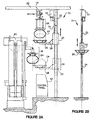
- FIGURE 2A shows, in summary, a monorail carrier 18 suspended from a monorail 22 .
- Green tire 24 is suspended by the carrier's tire-grasping mechanism 26 , which can expand or contract in order to grasp or release the green tire 24 .
- the tire-grasping mechanism 26 of the monorail carrier 18 releases the green tire 24 into an elevator system 31 which includes a basket 28 attached to an elevator 30 that rides on a vertical support rail 32 .
- FIGURE 2B shows a second view of the elevator system 31 , with its elevator 30 , vertical support rail 32 , and the chain or cable 34 driven by conventional means, such as the motor 33 , to raise or lower the basket 28 and the elevator 30 .
- Elevator system generally refers to the intermediate tire conveying system, comprising an elevator 30 with an attached basket 28 that can move upward or downward in a vertical path with respect to vertical support 32 , which receives individual green tires from the monorail carrier and moves the tires to within grasping range of the press loader 38 by each tire press 40 as discussed hereinafter.
- the monorail carrier 18 deposits the green tire 24 at a first or upper location in the basket 28 attached to the elevator 30 , after which the elevator 30 moves along a vertical path to a second or lower position or location 36 , as shown in FIGURE 2A .
- the green tire 24 in the basket 28 attached to the elevator 30 in the lower position 36 can then be carried in the basket 28 , as the basket moves through a circular arc with respect to elevator 30 , the radius of which arc is defined by the arm 29 which supports the basket 28 .
- the basket can either move through the arc in conjunction with its movement along the vertical path or subsequent to arriving at the lower location where the green tire is transferred to the loader 38 , which is typically an integral part of the tire press 40 .
- the arm portion of the loader 38 rotates within a horizontal plane in such a way as to allow the loader to retrieve the tire 24 from the elevator basket 28 and then deliver the tire into the press 40 .
- a control panel 42 at the site of the press 40 allows onsite manual control and override of the automated processes in the event of emergencies or in case of the need for specialized control or override of the automated processes.
- FIGURE 3A shows the tire press 40 in the open position, with the upper mold half 44 raised.
- the press loaders 38 which operate in conjunction with each press 40 have two degrees of motion: they can move up and down, and they can rotate within a horizontal plane. For example, as shown in FIGURE 2A , loaders 38 can retrieve green tires from the basket 28 of the elevator system 31 and then move each green tire 24 into the press 40 .
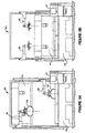
- FIGURE 3B shows the tire press 40 in the closed position, with the upper mold half 44 in a lowered position in relation to the lower mold half 46 . The press 40 is closed after the tires 24 have been loaded into the press.
- FIGURE 4 is a top view of the lower part 46 of the press 40 .
- Superstructure 50 supports the vertical support rails 32 of the elevator system 31 with its elevator 30 and the elevator's basket 28 and moveable arm 29 .
- the basket 28 is able to swing through an angular arc ⁇ within a horizontal plane from the first location where the basket 28 receives the green tire 24 to the lower, second location prior to the green tire being handed off to the loader 38 of the press.
- the arm of the loader 38 is able to pivot through an angle ⁇ about the loader's vertical support structure 49 as it receives the tire 24 from the basket 28 of the elevator 30 (which is unlabelled as such in FIGURE 4 and shows only the vertical support rail or girder 32 upon which the elevator moves upward or downward).
- the top part or mold half 44 of the press 40 lifts vertically upward from the lower part or mold half 46 of the press.
- Older style presses, ones of the "watch-case” design had upper mold sections that opened by hinging backward in such a way that the lower mold sections of the press were directly accessible from above.
- the older watch-case style presses allowed for the loading of the green tires into the press directly from above, rather than requiring them to be brought in from the side, as in the case of the newer style presses in which the upper mold section rises vertically rather than hinging backward and out of the way.
- the elevator system 31 of the present invention and the associated parts such as the vertical support rail or beam 32 , the elevator 30 and arm 29 and the basket.
- the elevator 30 receives in the basket 28 the green tire 24 from the monorail carrier 18 at a first location.
- the elevator 30 is then lowered with its basket to a second location at which the arm and basket can angularly move within a horizontal plane with respect to the elevator so that the tire can be transferred to the press loader 38 of the press 40 .
- the press loader 38 loads the green tire by moving the tire horizontally into the press.
- the basket 28 is generally unmovably attached to the arm 2 9, it is also within the terms of the invention to provide a power system (not shown) that rotates the basket 28 with respect to arm 29 so that the angular position at which the green tire is loaded into a tire press can be easily controlled.
- the elevator system 31 and its related parts, shown in FIGURES 2A, 2B, 4 and 5A, are an essential feature of the present invention.
- the elevator system 31 allows for the automated transfer of green tires into the new style tire presses, i.e., presses which have top mold halves 44 that lift vertically off from the bottom mold halves 31 of the present invention.
- Another significant advantage of using the elevator system, as an intermediate step in the transfer of the green tire from the monorail to the tire press is that the elevator 30 provides an inherent intermediate tire storage or buffer for tires awaiting processing within each respective tire press 40 while the monorail carrier is free to transfer another green tire to another press.
- Earlier style automated green tire transfer systems most notably the one described in U.S.
- Patent 4,268,219 by Nakagawa et al. allowed a remotely controlled overhead conveyor system to deliver green tires directly into older style presses in which the top of the press, when open, was hinged back out of the way from the bottom of the press. That is to say, the top of the old-style watch-case press did not interfere with the vertical delivery of the tire directly downward into the press.
- the disadvantage of these prior art systems was that more monorail carriers were required or the transfer was slower because the monorail carrier was held up at a specific press until the tire was inserted therein.
- the present invention reduces the need for monorail carriers because the use of the elevator system 31 introduces an additional tire buffer storage system right at the location of each of the tire presses whereby a green tire can be delivered and immediately transferred into a basket 28 to free up the monorail carrier. Moreover, the tires can then be transferred to the tire loader associated with each press so that two tires are in the tire buffer storage provided at each press, i.e. one in the basket and the other in the loader.
- the elevator systems in conjunction with the press loaders associated with each tire press, provide at the site of each press, a two-tier tire storage buffer, thereby increasing the efficiency and speed of transporting green tires from the building area 12 to the tire press area 14 .
- FIGURE 5A shows a second embodiment of an elevator system 54 .
- the vertical support rail 56 of the elevator system 54 is suspended from an upper support beam 59 which, in FIGURE 5A , is ceiling-suspended.
- the vertical support rail 56 is not mounted upon or anchored to the floor, as is the embodiment shown in FIGURES 2A and 2B .
- the monorail carrier 18 delivers the green tire 24 into the basket 28 when the basket is in the elevated position 58 at a first location along a vertical path which is parallel to an axis through rail 56 .
- the basket 28 is then lowered, and rotated i.e., pivoted within a horizontal plane about the elevator's vertical support rail 56 , into a third position or location where the green tire 24 can be retrieved by the loader 38 and then loaded into the press 40.
- FIGURE 5B shows, in simplified schematic form, a third embodiment of the elevator system 63 wherein the arm 29 that supports the basket 28 is not able to rotate in a horizontal plane about the ceiling mounted vertical support post 57 .
- the elevator's basket 28 receives the tire from a monorail carrier (not shown) when the elevator system 63 is in the location designated by A .
- the elevator system then moves translationally, under the power of conventional means such as motor 62 , along the upper rail 60 to the location designated by B at which point the green tire 24 can be received by the loader 38 associated with a press, not shown in FIGURE 5B .
Landscapes
- Engineering & Computer Science (AREA)
- Mechanical Engineering (AREA)
- Moulds For Moulding Plastics Or The Like (AREA)
- Tyre Moulding (AREA)
- Heating, Cooling, Or Curing Plastics Or The Like In General (AREA)
- Automobile Manufacture Line, Endless Track Vehicle, Trailer (AREA)
Applications Claiming Priority (1)
| Application Number | Priority Date | Filing Date | Title |
|---|---|---|---|
| PCT/US1998/026724 WO2000035665A2 (en) | 1998-12-16 | 1998-12-16 | Automated green tire conveyance system |
Publications (2)
| Publication Number | Publication Date |
|---|---|
| EP1140477A2 EP1140477A2 (en) | 2001-10-10 |
| EP1140477B1 true EP1140477B1 (en) | 2003-03-12 |
Family
ID=22268486
Family Applications (1)
| Application Number | Title | Priority Date | Filing Date |
|---|---|---|---|
| EP98963973A Expired - Lifetime EP1140477B1 (en) | 1998-12-16 | 1998-12-16 | Automated green tire conveyance system |
Country Status (9)
| Country | Link |
|---|---|
| EP (1) | EP1140477B1 (enExample) |
| JP (1) | JP4510297B2 (enExample) |
| AU (1) | AU1919199A (enExample) |
| BR (1) | BR9816089A (enExample) |
| CA (1) | CA2354403C (enExample) |
| DE (1) | DE69812192T2 (enExample) |
| ES (1) | ES2194384T3 (enExample) |
| WO (1) | WO2000035665A2 (enExample) |
| ZA (1) | ZA997449B (enExample) |
Families Citing this family (8)
| Publication number | Priority date | Publication date | Assignee | Title |
|---|---|---|---|---|
| US6908584B2 (en) | 2002-08-16 | 2005-06-21 | John R. Cole | Apparatus and method for locking a tire vulcanizing press |
| ES2293812B2 (es) * | 2003-08-07 | 2010-02-18 | John R. Cole | Aparato y metodo para bloquear una prensa de vulcanizacion de cubiertas. |
| FI125064B (fi) * | 2005-06-01 | 2015-05-15 | Cimcorp Oy | Rengasaihion siirrin |
| ITTO20060476A1 (it) * | 2006-06-28 | 2007-12-29 | Bridgestone Corp | Dispositivo di presa telescopico per il trasferimento di un pneumatico |
| JP5206090B2 (ja) * | 2008-04-24 | 2013-06-12 | 横浜ゴム株式会社 | 未加硫タイヤの供給方法、供給装置及び供給システム |
| ITMI20122233A1 (it) * | 2012-12-27 | 2014-06-28 | Pirelli | Metodo ed impianto per gestire pneumatici crudi |
| KR102398234B1 (ko) * | 2014-11-18 | 2022-05-13 | 하부르크-프로이덴베르거 마쉬넨바우 게엠베하 | 타이어 미가공품을 처리하기 위한 타이어 가열 프레스 및 운송 설비의 배치 방법 |
| BR112019006179B1 (pt) * | 2016-10-11 | 2022-09-20 | Pirelli Tyre S.P.A. | Método para manusear um pneu verde, e, instalação para a produção de pneus |
Family Cites Families (18)
| Publication number | Priority date | Publication date | Assignee | Title |
|---|---|---|---|---|
| NL251776A (enExample) * | 1959-05-19 | |||
| US3053400A (en) * | 1959-09-08 | 1962-09-11 | Us Rubber Co | Automatic tire carcass loading apparatus |
| DD117200A1 (enExample) * | 1974-12-10 | 1976-01-05 | ||
| JPS51126275A (en) * | 1975-04-25 | 1976-11-04 | Kobe Steel Ltd | Suspending * conveying and equipping method for green tire |
| JPS51123286A (en) * | 1975-04-21 | 1976-10-27 | Kobe Steel Ltd | Suspending * conveying and equipping apparatus for green tire |
| FR2308565A1 (fr) * | 1975-04-21 | 1976-11-19 | Kobe Steel Ltd | Procede et dispositif de transport de pneumatiques non vulcanises |
| IT1143821B (it) * | 1977-08-12 | 1986-10-22 | F A T A Fabbrica Ed Apparecchi | Sistema per l alimentazione di prodotti di materiale elastomero crudo ad autoclavi di vulcanizzazione |
| US4778060A (en) * | 1985-09-30 | 1988-10-18 | The Uniroyal Goodrich Tire Company | Tire processing system |
| JPH0772009B2 (ja) * | 1989-12-07 | 1995-08-02 | 住友ゴム工業株式会社 | 生タイヤ搬送装置 |
| JP2686375B2 (ja) * | 1991-04-23 | 1997-12-08 | 三菱重工業株式会社 | タイヤ製造装置 |
| JP2547740Y2 (ja) * | 1991-12-27 | 1997-09-17 | 横浜ゴム株式会社 | 加硫機へのグリーンタイヤの供給装置 |
| JP3116244B2 (ja) * | 1991-12-27 | 2000-12-11 | 横浜ゴム株式会社 | 成形工程と加硫工程との間のグリーンタイヤの搬送供給方法及びその装置 |
| JPH0797175A (ja) * | 1993-09-28 | 1995-04-11 | Bridgestone Corp | 輪状体の搬送装置 |
| JPH07117055A (ja) * | 1993-10-21 | 1995-05-09 | Kobe Steel Ltd | タイヤ加硫機に対するローダシステム及びローダ方法 |
| US5395150A (en) * | 1993-10-29 | 1995-03-07 | National Feedscrew & Machining Ind., Inc. | Loader basket assembly for tire press |
| JP2825218B2 (ja) * | 1994-05-27 | 1998-11-18 | 株式会社神戸製鋼所 | タイヤ搬送ローダ |
| JPH0857858A (ja) * | 1994-08-25 | 1996-03-05 | Kobe Steel Ltd | タイヤ加硫システム |
| JP3520940B2 (ja) * | 1995-08-25 | 2004-04-19 | 横浜ゴム株式会社 | グリーンタイヤの保管搬送方法及びその装置 |
-
1998
- 1998-12-16 AU AU19191/99A patent/AU1919199A/en not_active Abandoned
- 1998-12-16 WO PCT/US1998/026724 patent/WO2000035665A2/en not_active Ceased
- 1998-12-16 ES ES98963973T patent/ES2194384T3/es not_active Expired - Lifetime
- 1998-12-16 BR BR9816089-3A patent/BR9816089A/pt active Search and Examination
- 1998-12-16 EP EP98963973A patent/EP1140477B1/en not_active Expired - Lifetime
- 1998-12-16 CA CA002354403A patent/CA2354403C/en not_active Expired - Fee Related
- 1998-12-16 JP JP2000587957A patent/JP4510297B2/ja not_active Expired - Fee Related
- 1998-12-16 DE DE69812192T patent/DE69812192T2/de not_active Expired - Fee Related
-
1999
- 1999-12-02 ZA ZA9907449A patent/ZA997449B/xx unknown
Also Published As
| Publication number | Publication date |
|---|---|
| CA2354403A1 (en) | 2000-06-22 |
| DE69812192D1 (de) | 2003-04-17 |
| EP1140477A2 (en) | 2001-10-10 |
| JP2002532284A (ja) | 2002-10-02 |
| CA2354403C (en) | 2007-08-28 |
| AU1919199A (en) | 2000-07-03 |
| JP4510297B2 (ja) | 2010-07-21 |
| BR9816089A (pt) | 2001-08-21 |
| ZA997449B (en) | 2000-06-05 |
| WO2000035665A2 (en) | 2000-06-22 |
| ES2194384T3 (es) | 2003-11-16 |
| DE69812192T2 (de) | 2003-11-20 |
| WO2000035665A3 (en) | 2000-08-03 |
Similar Documents
| Publication | Publication Date | Title |
|---|---|---|
| US6746557B2 (en) | Bead loading method and apparatus | |
| US7195047B2 (en) | Tire manufacturing module and method of manufacturing tires | |
| US6499980B1 (en) | Automated green tire conveyance system | |
| EP1140477B1 (en) | Automated green tire conveyance system | |
| US20040238102A1 (en) | Method for manufacturing tires on a flexible manufacturing system | |
| JP5907953B2 (ja) | 車両の車輪用タイヤの構築における成形ドラムの管理の制御方法、および車両の車輪用タイヤの生産用プラント | |
| US7802975B2 (en) | Loading apparatus for assembly and disassembly of a tire curing mold | |
| US6773530B2 (en) | Method for manufacturing tires on a flexible manufacturing system | |
| US7785061B2 (en) | Apparatus and method for reorienting a tire and core assembly in a tire manufacturing line | |
| EP1295705B1 (en) | Stabilizer for cantilevered tire building drum | |
| JPWO2007091315A1 (ja) | タイヤの製造方法および製造設備 | |
| JPH08174709A (ja) | シングルステージ式タイヤ成形システム | |
| US5035567A (en) | Unloader for tire building system | |
| JP5206090B2 (ja) | 未加硫タイヤの供給方法、供給装置及び供給システム | |
| MXPA01005919A (en) | Automated green tire conveyance system | |
| KR102159663B1 (ko) | 차륜용 타이어를 생산하는 설비 및 방법 | |
| US20250108577A1 (en) | Tire manufacturing method and manufacturing system | |
| US6523594B1 (en) | Tire retreading plant |
Legal Events
| Date | Code | Title | Description |
|---|---|---|---|
| PUAI | Public reference made under article 153(3) epc to a published international application that has entered the european phase |
Free format text: ORIGINAL CODE: 0009012 |
|
| 17P | Request for examination filed |
Effective date: 20010716 |
|
| AK | Designated contracting states |
Kind code of ref document: A2 Designated state(s): DE ES FR GB IT |
|
| GRAG | Despatch of communication of intention to grant |
Free format text: ORIGINAL CODE: EPIDOS AGRA |
|
| 17Q | First examination report despatched |
Effective date: 20020508 |
|
| GRAG | Despatch of communication of intention to grant |
Free format text: ORIGINAL CODE: EPIDOS AGRA |
|
| GRAH | Despatch of communication of intention to grant a patent |
Free format text: ORIGINAL CODE: EPIDOS IGRA |
|
| GRAH | Despatch of communication of intention to grant a patent |
Free format text: ORIGINAL CODE: EPIDOS IGRA |
|
| GRAA | (expected) grant |
Free format text: ORIGINAL CODE: 0009210 |
|
| AK | Designated contracting states |
Designated state(s): DE ES FR GB IT |
|
| REG | Reference to a national code |
Ref country code: GB Ref legal event code: FG4D |
|
| REF | Corresponds to: |
Ref document number: 69812192 Country of ref document: DE Date of ref document: 20030417 Kind code of ref document: P |
|
| ET | Fr: translation filed | ||
| REG | Reference to a national code |
Ref country code: ES Ref legal event code: FG2A Ref document number: 2194384 Country of ref document: ES Kind code of ref document: T3 |
|
| PLBE | No opposition filed within time limit |
Free format text: ORIGINAL CODE: 0009261 |
|
| STAA | Information on the status of an ep patent application or granted ep patent |
Free format text: STATUS: NO OPPOSITION FILED WITHIN TIME LIMIT |
|
| 26N | No opposition filed |
Effective date: 20031215 |
|
| PGFP | Annual fee paid to national office [announced via postgrant information from national office to epo] |
Ref country code: ES Payment date: 20071219 Year of fee payment: 10 |
|
| PGFP | Annual fee paid to national office [announced via postgrant information from national office to epo] |
Ref country code: IT Payment date: 20071217 Year of fee payment: 10 |
|
| PGFP | Annual fee paid to national office [announced via postgrant information from national office to epo] |
Ref country code: GB Payment date: 20071106 Year of fee payment: 10 |
|
| PGFP | Annual fee paid to national office [announced via postgrant information from national office to epo] |
Ref country code: DE Payment date: 20071228 Year of fee payment: 10 |
|
| PGFP | Annual fee paid to national office [announced via postgrant information from national office to epo] |
Ref country code: FR Payment date: 20071204 Year of fee payment: 10 |
|
| GBPC | Gb: european patent ceased through non-payment of renewal fee |
Effective date: 20081216 |
|
| REG | Reference to a national code |
Ref country code: FR Ref legal event code: ST Effective date: 20090831 |
|
| PG25 | Lapsed in a contracting state [announced via postgrant information from national office to epo] |
Ref country code: DE Free format text: LAPSE BECAUSE OF NON-PAYMENT OF DUE FEES Effective date: 20090701 |
|
| PG25 | Lapsed in a contracting state [announced via postgrant information from national office to epo] |
Ref country code: GB Free format text: LAPSE BECAUSE OF NON-PAYMENT OF DUE FEES Effective date: 20081216 |
|
| REG | Reference to a national code |
Ref country code: ES Ref legal event code: FD2A Effective date: 20081217 |
|
| PG25 | Lapsed in a contracting state [announced via postgrant information from national office to epo] |
Ref country code: FR Free format text: LAPSE BECAUSE OF NON-PAYMENT OF DUE FEES Effective date: 20081231 Ref country code: ES Free format text: LAPSE BECAUSE OF NON-PAYMENT OF DUE FEES Effective date: 20081217 |
|
| PG25 | Lapsed in a contracting state [announced via postgrant information from national office to epo] |
Ref country code: IT Free format text: LAPSE BECAUSE OF NON-PAYMENT OF DUE FEES Effective date: 20081216 |