EP1139493A2 - Elektrischer Verbinder zum Anschluss von elektrischen Leitern an ein elektrisches Gerät - Google Patents
Elektrischer Verbinder zum Anschluss von elektrischen Leitern an ein elektrisches Gerät Download PDFInfo
- Publication number
- EP1139493A2 EP1139493A2 EP01106458A EP01106458A EP1139493A2 EP 1139493 A2 EP1139493 A2 EP 1139493A2 EP 01106458 A EP01106458 A EP 01106458A EP 01106458 A EP01106458 A EP 01106458A EP 1139493 A2 EP1139493 A2 EP 1139493A2
- Authority
- EP
- European Patent Office
- Prior art keywords
- contact carrier
- electrical connector
- insulation displacement
- connector according
- displacement contacts
- Prior art date
- Legal status (The legal status is an assumption and is not a legal conclusion. Google has not performed a legal analysis and makes no representation as to the accuracy of the status listed.)
- Granted
Links
Images


Classifications
-
- H—ELECTRICITY
- H01—ELECTRIC ELEMENTS
- H01R—ELECTRICALLY-CONDUCTIVE CONNECTIONS; STRUCTURAL ASSOCIATIONS OF A PLURALITY OF MUTUALLY-INSULATED ELECTRICAL CONNECTING ELEMENTS; COUPLING DEVICES; CURRENT COLLECTORS
- H01R9/00—Structural associations of a plurality of mutually-insulated electrical connecting elements, e.g. terminal strips or terminal blocks; Terminals or binding posts mounted upon a base or in a case; Bases therefor
- H01R9/03—Connectors arranged to contact a plurality of the conductors of a multiconductor cable, e.g. tapping connections
- H01R9/031—Connectors arranged to contact a plurality of the conductors of a multiconductor cable, e.g. tapping connections for multiphase cables, e.g. with contact members penetrating insulation of a plurality of conductors
-
- H—ELECTRICITY
- H01—ELECTRIC ELEMENTS
- H01R—ELECTRICALLY-CONDUCTIVE CONNECTIONS; STRUCTURAL ASSOCIATIONS OF A PLURALITY OF MUTUALLY-INSULATED ELECTRICAL CONNECTING ELEMENTS; COUPLING DEVICES; CURRENT COLLECTORS
- H01R12/00—Structural associations of a plurality of mutually-insulated electrical connecting elements, specially adapted for printed circuits, e.g. printed circuit boards [PCB], flat or ribbon cables, or like generally planar structures, e.g. terminal strips, terminal blocks; Coupling devices specially adapted for printed circuits, flat or ribbon cables, or like generally planar structures; Terminals specially adapted for contact with, or insertion into, printed circuits, flat or ribbon cables, or like generally planar structures
- H01R12/70—Coupling devices
- H01R12/71—Coupling devices for rigid printing circuits or like structures
- H01R12/75—Coupling devices for rigid printing circuits or like structures connecting to cables except for flat or ribbon cables
-
- H—ELECTRICITY
- H01—ELECTRIC ELEMENTS
- H01R—ELECTRICALLY-CONDUCTIVE CONNECTIONS; STRUCTURAL ASSOCIATIONS OF A PLURALITY OF MUTUALLY-INSULATED ELECTRICAL CONNECTING ELEMENTS; COUPLING DEVICES; CURRENT COLLECTORS
- H01R13/00—Details of coupling devices of the kinds covered by groups H01R12/70 or H01R24/00 - H01R33/00
- H01R13/46—Bases; Cases
- H01R13/516—Means for holding or embracing insulating body, e.g. casing, hoods
-
- H—ELECTRICITY
- H01—ELECTRIC ELEMENTS
- H01R—ELECTRICALLY-CONDUCTIVE CONNECTIONS; STRUCTURAL ASSOCIATIONS OF A PLURALITY OF MUTUALLY-INSULATED ELECTRICAL CONNECTING ELEMENTS; COUPLING DEVICES; CURRENT COLLECTORS
- H01R12/00—Structural associations of a plurality of mutually-insulated electrical connecting elements, specially adapted for printed circuits, e.g. printed circuit boards [PCB], flat or ribbon cables, or like generally planar structures, e.g. terminal strips, terminal blocks; Coupling devices specially adapted for printed circuits, flat or ribbon cables, or like generally planar structures; Terminals specially adapted for contact with, or insertion into, printed circuits, flat or ribbon cables, or like generally planar structures
- H01R12/70—Coupling devices
- H01R12/71—Coupling devices for rigid printing circuits or like structures
- H01R12/712—Coupling devices for rigid printing circuits or like structures co-operating with the surface of the printed circuit or with a coupling device exclusively provided on the surface of the printed circuit
- H01R12/716—Coupling device provided on the PCB
- H01R12/718—Contact members provided on the PCB without an insulating housing
-
- H—ELECTRICITY
- H01—ELECTRIC ELEMENTS
- H01R—ELECTRICALLY-CONDUCTIVE CONNECTIONS; STRUCTURAL ASSOCIATIONS OF A PLURALITY OF MUTUALLY-INSULATED ELECTRICAL CONNECTING ELEMENTS; COUPLING DEVICES; CURRENT COLLECTORS
- H01R13/00—Details of coupling devices of the kinds covered by groups H01R12/70 or H01R24/00 - H01R33/00
- H01R13/40—Securing contact members in or to a base or case; Insulating of contact members
- H01R13/42—Securing in a demountable manner
- H01R13/428—Securing in a demountable manner by resilient locking means on the contact members; by locking means on resilient contact members
- H01R13/432—Securing in a demountable manner by resilient locking means on the contact members; by locking means on resilient contact members by stamped-out resilient tongue snapping behind shoulder in base or case
-
- Y—GENERAL TAGGING OF NEW TECHNOLOGICAL DEVELOPMENTS; GENERAL TAGGING OF CROSS-SECTIONAL TECHNOLOGIES SPANNING OVER SEVERAL SECTIONS OF THE IPC; TECHNICAL SUBJECTS COVERED BY FORMER USPC CROSS-REFERENCE ART COLLECTIONS [XRACs] AND DIGESTS
- Y10—TECHNICAL SUBJECTS COVERED BY FORMER USPC
- Y10S—TECHNICAL SUBJECTS COVERED BY FORMER USPC CROSS-REFERENCE ART COLLECTIONS [XRACs] AND DIGESTS
- Y10S439/00—Electrical connectors
- Y10S439/901—Connector hood or shell
- Y10S439/903—Special latch for insert
Definitions
- the invention relates to an electrical connector for connecting electrical Conductors to an electrical device, insulation displacement contacts being provided, which are held in a contact carrier.
- Such an electrical connector is for a fixed, through the use of Insulation displacement contacts but also releasable connection from an electrical Device provided with one or more electrical conductors.
- DE 197 55 530 describes a device for electrical strain relief and / or optical cable known in which the insulation displacement in a corresponding Forming are firmly connected to a housing in which one for Insulation clamps provided cable guide part and a conductor guide part with be screwed onto a union nut.
- the invention is therefore based on the object of an electrical connector trained in such a way that a simple assembly is possible.
- an electrical connector for connection created from electrical conductors to an electrical device from a receptacle, a contact carrier, which is in the receptacle is arranged insulation displacement contacts in the contact carrier are held, and locking means by means of which the contact carrier in the receptacle is held.
- This design allows using the contact carrier pre-assemble the insulation displacement terminals and then insert them into the receptacle, where it automatically by means of the locking means in a simple manner locked.
- the contact carrier can be automated or by hand in the Recording socket are used.
- the locking means can be in the form of a wart-like cam in the receiving socket be formed, which engage in an annular groove in the contact carrier.
- This Locking means can be easily produced with plastic parts become.
- the locking means can alternatively from a recess in the contact carrier and a mounting pin that can be inserted into the recess is.
- the fastening pin can be attached to a plate-shaped fastening element be provided in a slot between two parallel spaced Walls of a housing of the electrical device can be inserted, wherein the mounting pin engages in the recess in the contact carrier and wherein molded the fastener on a lid of the electrical device is. In this way, the contact carrier is automatically in the receptacle set when the housing of the electrical device is closed becomes.
- the insulation displacement contacts are preferably in receiving slots in the contact carrier held by means of latches. This enables the insulation displacement contacts just slide it into the contact carrier so that it is there automatically latch.
- the insulation displacement contacts at their device-side connection ends with plug connections are provided so that without complex connection work such as soldering etc. Cable lugs attached or the connection ends in bores or contact springs a PCB can be inserted.
- the insulation displacement contacts are inserted into the contact carrier, in which they automatically lock.
- the one with the insulation displacement contacts equipped contact carrier is inserted into the socket, in which it automatically locks.
- the contact carrier When inserting the contact carrier the terminal ends of the insulation displacement contacts automatically into them assigned contact elements inserted in the electrical device, for example in the contact springs. So it is not soldering or complex Assembly work required; the electrical connection can even can be produced on site without special tools.
- the invention also relates to a contact carrier with insulation displacement contacts, which are held in the contact carrier and locking means, by means of which the contact carrier are held in a receptacle can, the insulation displacement contacts provided with a connection end by means of which they are inserted into a cable lug or a contact spring can be.
- the invention further relates to an electrical device with an electrical connector as described above.
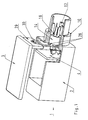
- an electrical device 1 is shown, the housing 2 and has a cover 3.
- a circuit board 4 is arranged inside the housing, which serves as a carrier for electronic components, not shown.
- a plurality of contacts 5 are inserted, each resilient Have double legs.
- a cylindrical receptacle 10 is mounted on it Inside is provided with guide ribs 12.
- the side wall of the case 2, on which the mounting socket is attached, is double-walled,
- a contact carrier 14 is arranged in the interior of the receptacle slot-shaped recesses 16 is provided.
- each recess 16 is one Insulation displacement contact 18 arranged on one side with two opposite one another Insulation displacement terminals 20 and on the other hand with a pin-shaped Connection end 22 is provided.
- Each insulation displacement contact points in the middle a locking tab 24 which cooperate with a shoulder 26 in the contact carrier 14 can.
- the contact carrier is provided with three cutouts 28, one of which is shown in FIG. 1 only two can be seen.
- the third recess is in relation to the upper recess mirror image of the front recess, arranged diagonally below.
- the cover 3 of the device 1 is provided with a fastening element 29 which a locking pin 30 is arranged, which in one of the recesses 28th can intervene.
- the insulation displacement contacts are made of metal and the contact carrier is made made of an insulating plastic.
- the assembly of the electrical connection coming from the contact carrier with the Insulation displacement contacts and the receptacle is made in the following Way: First, the contact carrier 14 with the insulation displacement contacts 18 equipped by pushing them into the recess 16 until the locking tab 24 engages behind the shoulder 26 of the contact carrier. The insulation displacement contacts 18 are then firmly received in the contact carrier. Then the in this way equipped contact carrier from the outside in the receiving socket 10 so inserted that the connection ends 22 of the insulation displacement contacts 18 in the Extend inside the electrical device. The correct alignment of the contact carrier is ensured by the guide rib 12 with a suitable Groove in the contact carrier interacts. When inserting the contact carrier the connection ends 22 of the insulation displacement contacts between the double legs of contacts 5 inserted so that there the electrical contact done automatically.
- the cover 3 is placed on the housing 2, the fastener 29 of the lid 2 in the space between the two side walls of the housing can dip and the locking pin 30 engages in the recess 28 in the contact carrier.
- the recess 28 and the locking pin 30 then act as a locking means by means of which Contact carrier is held firmly in the receptacle.
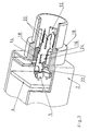
- FIGS. 4 and 5 A second embodiment is shown in FIGS. 4 and 5, wherein for the Components known from the first embodiment have the same reference numerals be used. In this regard, reference is made to the above explanations.
- the electrical device is also here with a cylindrical receptacle 10 provided, in which the contact carrier 14 is inserted.
- the insulation displacement contacts 18 are not provided with latching tabs provided, but with mounting tabs 25, by means of which they on the contact carrier 14 are attached.
- the contact carrier 14 is in the second embodiment with an apron 38 provided which surrounds the insulation displacement contacts 20 of the insulation displacement contacts.
- apron 38 On On the inside of the apron 38, guide ribs 40 are formed, which act as an anti-rotation device serve for a pressure part, which are pressed into the apron 38 can and the conductors to be connected in the free space between the opposite Insulation displacement 20 presses.
- On the outside of the apron 38 a sealing ring 42 is arranged.
- the contacts 5 have in the second Embodiment no double leg, but are as resilient socket contacts executed.
- the locking means for fixing the contact carrier 14 in the receptacle 10 consist of an annular groove 32 in the second embodiment the outer circumference of the contact carrier 14 and of wart-shaped cams 34 the inner wall of the receptacle 10. If the with the insulation displacement contacts 18 equipped contact carrier 14 inserted into the receptacle 10 the cams 34 snap into the groove 32, an additional step 36 bears on the contact carrier 14 on the end face of the receiving connector 10. At the Pushing the contact carrier into the receptacle is the pin-shaped Terminal ends 22 of the insulation displacement contacts 18 are pushed back into the contacts 5.
Landscapes
- Connections By Means Of Piercing Elements, Nuts, Or Screws (AREA)
- Coupling Device And Connection With Printed Circuit (AREA)
- Details Of Connecting Devices For Male And Female Coupling (AREA)
- Multi-Conductor Connections (AREA)
- Connector Housings Or Holding Contact Members (AREA)
Abstract
Description
- 1:
- Elektrisches Gerät
- 2:
- Gehäuse
- 3:
- Deckel
- 4:
- Leiterplatte
- 5:
- Kontakt
- 10:
- Aufnahmestutzen
- 12:
- Führungsrippe
- 14:
- Kontaktträger
- 16:
- Ausnehmung
- 18:
- Schneidklemmkontakt
- 20:
- Schneidklemme
- 22:
- Anschlußende
- 24:
- Rastlasche
- 25:
- Befestigungslasche
- 26:
- Schulter
- 28:
- Aussparung
- 29:
- Befestigungselement
- 30:
- Verriegelungszapfen
- 32:
- Nut
- 34:
- Nocken
- 36:
- Absatz
- 38:
- Schürze
- 40:
- Führungsrippe
- 42:
- Dichtring
Claims (12)
- Elektrischer Verbinder zum Anschließen von elektrischen Leitern an ein elektrisches Gerät (1), bestehend aus einem Aufnahmestutzen (10), einem Kontaktträger (14), der in dem Aufnahmestutzen angeordnet ist, Schneidklemmkontakten (18), die in dem Kontaktträger (14) gehalten sind, und Arretierungsmitteln (28, 30; 32, 34), mittels denen der Kontaktträger (14) im Aufnahmestutzen (10) gehalten ist.
- Elektrischer Verbinder nach Anspruch 1, dadurch gekennzeichnet, daß der Kontaktträger (14) mittels Polarisationsmitteln (12) im Aufnahmestutzen (10) verdrehsicher gehalten ist.
- Elektrischer Verbinder nach Anspruch 1 oder 2, dadurch gekennzeichnet, daß die Arretierungsmittel aus warzenförmigen Nocken (34) im Aufnahmestutzen (10) und einer ringförmigen Nut (32) im Kontaktträger (14) bestehen, in die die Nocken eingreifen.
- Elektrischer Verbinder nach Anspruch 1 oder 2, dadurch gekennzeichnet, daß die Arretierungsmittel aus mindestens einer Ausnehmung (28) im Kontaktträger (14) und einem Befestigungszapfen (30) bestehen, der in die Ausnehmung einfügbar ist.
- Elektrischer Verbinder nach Anspruch 4, dadurch gekennzeichnet, daß der Befestigungszapfen an einem plattenförmigen Befestigungselement (29) vorgesehen ist und daß das Befestigungselement in einen Schlitz zwischen zwei parallel beabstandeten Wänden in einem Gehäuse (2) eines elektrischen Gerätes (1) einfügbar ist, wobei der Befestigungszapfen (30) in die Ausnehmung (28) im Kontaktträger (14) eingreift.
- Elektrischer Verbinder nach einem der vorstehenden Ansprüche, dadurch gekennzeichnet, daß das Befestigungselement an einem Deckel (3) des elektrischen Gerätes angeformt ist.
- Elektrischer Verbinder nach einem der vorstehenden Ansprüche, dadurch gekennzeichnet, daß die Schneidklemmkontakte (18) in Ausnehmungen (16) im Kontaktträger mittels Rastlaschen (24) gehalten sind.
- Elektrischer Verbinder nach Anspruch 7, dadurch gekennzeichnet, daß die Schneidklemmkontakte (18) von der Leiteranschlußseite des Aufnahmestutzens einsetzbar sind, wobei die Rastlaschen (24) hinter einer Schulter (26) in der Ausnehmung (16) im Kontaktträger verrasten.
- Elektrischer Verbinder nach einem der vorstehenden Ansprüche, dadurch gekennzeichnet, daß die geräteseitigen Anschlußenden der Schneidklemmkontakte mit Steckanschlüssen (22) für Kabelschuhe versehen sind.
- Elektrischer Verbinder nach einem der Ansprüche 1 bis 7, dadurch gekennzeichnet, daß die geräteseitigen Anschlußenden der Schneidklemmkontakte (18) mit stiftförmigen Anschlußenden (22) versehen sind, die in Bohrungen oder Kontaktfedern einer Leiterplatte (4) einfügbar sind.
- Kontaktträger (14) mit Schneidklemmkontakten (18), die in dem Kontaktträger gehalten sind, und Arretierungsmitteln (28; 32), mittels denen der Kontaktträger (14) in einem Aufnahmestutzen (10) gehalten werden kann, wobei die Schneidklemmkontakte (18) mit einem Anschlußende versehen sind, mittels dem sie in einen Kabelschuh oder eine Kontaktfeder eingesteckt werden können.
- Elektrisches Gerät (1) mit einem elektrischen Verbinder nach einem der Ansprüche 1 bis 10.
Applications Claiming Priority (4)
| Application Number | Priority Date | Filing Date | Title |
|---|---|---|---|
| DE20005868U DE20005868U1 (de) | 2000-03-30 | 2000-03-30 | Elektrischer Verbinder |
| DE20005868U | 2000-03-30 | ||
| DE20005870U | 2000-03-30 | ||
| DE20005870U DE20005870U1 (de) | 2000-03-30 | 2000-03-30 | Elektrischer Anschluss |
Publications (3)
| Publication Number | Publication Date |
|---|---|
| EP1139493A2 true EP1139493A2 (de) | 2001-10-04 |
| EP1139493A3 EP1139493A3 (de) | 2002-03-27 |
| EP1139493B1 EP1139493B1 (de) | 2003-10-08 |
Family
ID=26056177
Family Applications (1)
| Application Number | Title | Priority Date | Filing Date |
|---|---|---|---|
| EP01106458A Expired - Lifetime EP1139493B1 (de) | 2000-03-30 | 2001-03-23 | Elektrischer Verbinder zum Anschluss von elektrischen Leitern an ein elektrisches Gerät |
Country Status (6)
| Country | Link |
|---|---|
| US (1) | US6551144B2 (de) |
| EP (1) | EP1139493B1 (de) |
| JP (1) | JP3437839B2 (de) |
| AT (1) | ATE251807T1 (de) |
| DE (1) | DE50100736D1 (de) |
| ES (1) | ES2211680T3 (de) |
Cited By (1)
| Publication number | Priority date | Publication date | Assignee | Title |
|---|---|---|---|---|
| CN101847808A (zh) * | 2010-05-11 | 2010-09-29 | 上海图越电子有限公司 | Sma射频同轴连接器 |
Families Citing this family (11)
| Publication number | Priority date | Publication date | Assignee | Title |
|---|---|---|---|---|
| TW592402U (en) * | 2002-12-25 | 2004-06-11 | Lorom Ind Co Ltd | Cable distribution plate |
| DE20318593U1 (de) * | 2003-12-02 | 2004-02-26 | Harting Electric Gmbh & Co. Kg | Anordnung eines Elementes in einem Rundsteckverbinder |
| US7396259B2 (en) * | 2005-06-29 | 2008-07-08 | Fci Americas Technology, Inc. | Electrical connector housing alignment feature |
| JP4594198B2 (ja) * | 2005-09-02 | 2010-12-08 | 株式会社オートネットワーク技術研究所 | 電気接続箱 |
| DE102007031727A1 (de) * | 2006-08-31 | 2008-03-20 | Zf Friedrichshafen Ag | Verbindungselement zum Verbinden von elektrischen Leitern |
| CN200959432Y (zh) * | 2006-09-22 | 2007-10-10 | 富士康(昆山)电脑接插件有限公司 | 电连接器 |
| JP4285706B2 (ja) * | 2007-02-20 | 2009-06-24 | 日本航空電子工業株式会社 | コネクタ及びそれを備えた装置 |
| CN101599604A (zh) * | 2008-06-04 | 2009-12-09 | 鸿富锦精密工业(深圳)有限公司 | 线缆连接器 |
| JP6803734B2 (ja) * | 2016-12-01 | 2020-12-23 | イリソ電子工業株式会社 | 電子部品及び撮像装置 |
| CN109950719B (zh) * | 2017-12-20 | 2020-12-04 | 中航光电科技股份有限公司 | 一种射频同轴连接器 |
| CN119447840A (zh) * | 2025-01-09 | 2025-02-14 | 天津宜科自动化股份有限公司 | 一种绝缘刺破式圆形连接器结构 |
Family Cites Families (24)
| Publication number | Priority date | Publication date | Assignee | Title |
|---|---|---|---|---|
| US4629269A (en) | 1977-10-25 | 1986-12-16 | Allied Corporation | Electrical connector with environmental seal |
| GB2020917A (en) * | 1977-12-20 | 1979-11-21 | Winster Eng Ltd | Electrical connection device |
| DE3042293C2 (de) | 1980-11-08 | 1985-03-07 | Standard Elektrik Lorenz Ag, 7000 Stuttgart | Elektrischer Steckverbinder |
| EP0128472A2 (de) | 1983-06-03 | 1984-12-19 | Litton Systems, Inc. | Vor Ort reparierbarer vergossener Steckverbinder |
| JPH031903Y2 (de) * | 1985-05-13 | 1991-01-21 | ||
| US5046961A (en) * | 1990-11-26 | 1991-09-10 | Hubbell Incorporated | Positive locking electrical plug |
| AUPM658794A0 (en) * | 1994-07-04 | 1994-07-28 | Alcatel Components Limited | Electrical connector element |
| DE19504013C1 (de) * | 1995-02-07 | 1996-07-18 | Lumberg Karl Gmbh & Co | Anschlußvorrichtung zur wahlfreien Herstellung eines wiederverwendbaren elektrischen Anschlusses bzw. Abgriffs an mehradrigen elektrischen Leitungen |
| US5626486A (en) * | 1995-03-10 | 1997-05-06 | The Whitaker Corporation | High voltage low current connector interface with compressible terminal site seal |
| DE19605083A1 (de) * | 1995-03-24 | 1996-09-26 | Siemens Ag | Kabelanschlußeinrichtung |
| DE29512585U1 (de) | 1995-08-04 | 1995-11-30 | Phoenix Contact Gmbh & Co., 32825 Blomberg | Leiteranschlußelement |
| US5609499A (en) * | 1995-08-15 | 1997-03-11 | Hon Hai Precision Ind. Co., Ltd. | Cable connector assembly with reinforcement structure |
| US5871376A (en) | 1996-05-03 | 1999-02-16 | Tsai; Yen Hui | Electrical connector for computers |
| JPH10125408A (ja) * | 1996-10-17 | 1998-05-15 | Dai Ichi Denshi Kogyo Kk | 電気コネクタ及び電気コネクタへの結線方法 |
| DE19755530C2 (de) | 1997-06-18 | 2001-06-28 | Harting Kgaa | Einrichtung zur Zugentlastung elektrischer oder optischer Kabel |
| DE19725732C2 (de) | 1997-06-18 | 2000-09-28 | Harting Kgaa | Einrichtung zur Zugentlastung elektrischer oder optischer Kabel |
| DE19807938A1 (de) | 1997-12-18 | 1999-08-26 | Whitaker Corp | Steckverbinder bestehend aus einem Gehäuse und mindestens einem Kontakt |
| US6004172A (en) | 1998-04-01 | 1999-12-21 | Tri-Star Electronics International, Inc. | Two piece pin/socket contact |
| EP0961378B2 (de) * | 1998-05-28 | 2012-07-18 | Harting Electric GmbH & Co. KG | Kabeleinführung |
| ES2209284T3 (es) | 1998-06-19 | 2004-06-16 | Manfred Fladung Gmbh | Conector electrico reparable in situ. |
| DE19830799A1 (de) | 1998-07-09 | 2000-01-13 | Delphi Automotive Systems Gmbh | Elektrischer Verbinder |
| US6168478B1 (en) * | 1998-08-28 | 2001-01-02 | Lucent Technologies, Inc. | Snap type retention mechanism for connector terminals |
| JP3313329B2 (ja) * | 1998-10-21 | 2002-08-12 | ヒロセ電機株式会社 | 多極防水コネクタ |
| US6250963B1 (en) * | 1999-08-30 | 2001-06-26 | Osram Sylvania Inc. | Connector shell, connector assembly and method of fabricating same |
-
2001
- 2001-03-23 ES ES01106458T patent/ES2211680T3/es not_active Expired - Lifetime
- 2001-03-23 AT AT01106458T patent/ATE251807T1/de not_active IP Right Cessation
- 2001-03-23 DE DE50100736T patent/DE50100736D1/de not_active Expired - Fee Related
- 2001-03-23 EP EP01106458A patent/EP1139493B1/de not_active Expired - Lifetime
- 2001-03-27 JP JP2001090761A patent/JP3437839B2/ja not_active Expired - Fee Related
- 2001-03-29 US US09/821,197 patent/US6551144B2/en not_active Expired - Fee Related
Cited By (2)
| Publication number | Priority date | Publication date | Assignee | Title |
|---|---|---|---|---|
| CN101847808A (zh) * | 2010-05-11 | 2010-09-29 | 上海图越电子有限公司 | Sma射频同轴连接器 |
| CN101847808B (zh) * | 2010-05-11 | 2012-08-15 | 上海图越电子有限公司 | Sma射频同轴连接器 |
Also Published As
| Publication number | Publication date |
|---|---|
| JP2001297825A (ja) | 2001-10-26 |
| US6551144B2 (en) | 2003-04-22 |
| JP3437839B2 (ja) | 2003-08-18 |
| EP1139493A3 (de) | 2002-03-27 |
| US20010027051A1 (en) | 2001-10-04 |
| DE50100736D1 (de) | 2003-11-13 |
| ES2211680T3 (es) | 2004-07-16 |
| ATE251807T1 (de) | 2003-10-15 |
| EP1139493B1 (de) | 2003-10-08 |
Similar Documents
| Publication | Publication Date | Title |
|---|---|---|
| DE69120688T2 (de) | Mehrpoliger abgeschirmter verbinder mit gemeinsamer erdung | |
| DE60027611T2 (de) | Kabelverbinder mit gesteuerter Impedanz | |
| DE19746637C1 (de) | HF-Koaxial-Winkelsteckverbinderteil sowie Verfahren zum automatischen Zusammenbau | |
| DE68921165T2 (de) | Abgeschirmte Steckbuchse mit niedrigem Profil. | |
| DE102004038123B4 (de) | Elektrischer Stecker und elektrische Steckeraufnahme | |
| DE69524935T2 (de) | Abgeschirmte verbinderanordnung | |
| DE69313100T2 (de) | Abgeschirmte elektrische Verbinderanordnung | |
| DE102009056517B4 (de) | Steckverbinderanordnung mit erstem und zweitem Stecker und Gegenstecker | |
| EP1814202A2 (de) | Kupplung | |
| DE9101288U1 (de) | LAN-Schnittstelle | |
| DE19813458A1 (de) | Elektrischer Verbinder | |
| DE102008060642B4 (de) | Steckverbinder mit Erdungsplatte | |
| DE9311781U1 (de) | Kabelstecker für vieladrige Kabel | |
| DE20014791U1 (de) | Mehrpoliger Steckverbinder für elektronische Signalleitungen | |
| EP1575131A1 (de) | Elektrischer Steckverbinder | |
| EP1139493B1 (de) | Elektrischer Verbinder zum Anschluss von elektrischen Leitern an ein elektrisches Gerät | |
| DE4001104A1 (de) | Steckverbindung | |
| DE10008932A1 (de) | Elektrischer Stecker | |
| EP1154521B1 (de) | Steckverbinder und Verfahren zur Montage eines Steckverbinders | |
| EP3963674B1 (de) | Schnittstelle für leiterplatte | |
| DE102010034975A1 (de) | Elektronische Schaltung | |
| EP2099097A1 (de) | Verbindungsvorrichtung für die Leiter von zwei Kabeln | |
| EP2648285B1 (de) | Steckverbinder zur Montage in eine Gehäuseöffnung eines Gehäuses | |
| EP2381542A1 (de) | USB Steckbuchse | |
| EP1401062A1 (de) | Hausgeräte-Steckkontaktsystem |
Legal Events
| Date | Code | Title | Description |
|---|---|---|---|
| PUAI | Public reference made under article 153(3) epc to a published international application that has entered the european phase |
Free format text: ORIGINAL CODE: 0009012 |
|
| AK | Designated contracting states |
Kind code of ref document: A2 Designated state(s): AT BE CH CY DE DK ES FI FR GB GR IE IT LI LU MC NL PT SE TR |
|
| AX | Request for extension of the european patent |
Free format text: AL;LT;LV;MK;RO;SI |
|
| PUAL | Search report despatched |
Free format text: ORIGINAL CODE: 0009013 |
|
| AK | Designated contracting states |
Kind code of ref document: A3 Designated state(s): AT BE CH CY DE DK ES FI FR GB GR IE IT LI LU MC NL PT SE TR |
|
| AX | Request for extension of the european patent |
Free format text: AL;LT;LV;MK;RO;SI |
|
| RIC1 | Information provided on ipc code assigned before grant |
Free format text: 7H 01R 4/24 A, 7H 01R 13/639 B |
|
| 17P | Request for examination filed |
Effective date: 20020524 |
|
| 17Q | First examination report despatched |
Effective date: 20020722 |
|
| AKX | Designation fees paid |
Free format text: AT BE CH CY DE DK ES FI FR GB GR IE IT LI LU MC NL PT SE TR |
|
| GRAH | Despatch of communication of intention to grant a patent |
Free format text: ORIGINAL CODE: EPIDOS IGRA |
|
| GRAH | Despatch of communication of intention to grant a patent |
Free format text: ORIGINAL CODE: EPIDOS IGRA |
|
| GRAA | (expected) grant |
Free format text: ORIGINAL CODE: 0009210 |
|
| AK | Designated contracting states |
Kind code of ref document: B1 Designated state(s): AT BE CH CY DE DK ES FI FR GB GR IE IT LI LU MC NL PT SE TR |
|
| PG25 | Lapsed in a contracting state [announced via postgrant information from national office to epo] |
Ref country code: FI Free format text: LAPSE BECAUSE OF FAILURE TO SUBMIT A TRANSLATION OF THE DESCRIPTION OR TO PAY THE FEE WITHIN THE PRESCRIBED TIME-LIMIT Effective date: 20031008 Ref country code: CY Free format text: LAPSE BECAUSE OF FAILURE TO SUBMIT A TRANSLATION OF THE DESCRIPTION OR TO PAY THE FEE WITHIN THE PRESCRIBED TIME-LIMIT Effective date: 20031008 Ref country code: NL Free format text: LAPSE BECAUSE OF FAILURE TO SUBMIT A TRANSLATION OF THE DESCRIPTION OR TO PAY THE FEE WITHIN THE PRESCRIBED TIME-LIMIT Effective date: 20031008 Ref country code: TR Free format text: LAPSE BECAUSE OF FAILURE TO SUBMIT A TRANSLATION OF THE DESCRIPTION OR TO PAY THE FEE WITHIN THE PRESCRIBED TIME-LIMIT Effective date: 20031008 Ref country code: IE Free format text: LAPSE BECAUSE OF FAILURE TO SUBMIT A TRANSLATION OF THE DESCRIPTION OR TO PAY THE FEE WITHIN THE PRESCRIBED TIME-LIMIT Effective date: 20031008 |
|
| REG | Reference to a national code |
Ref country code: GB Ref legal event code: FG4D Free format text: NOT ENGLISH |
|
| REG | Reference to a national code |
Ref country code: CH Ref legal event code: EP |
|
| REG | Reference to a national code |
Ref country code: CH Ref legal event code: NV Representative=s name: TROESCH SCHEIDEGGER WERNER AG |
|
| REG | Reference to a national code |
Ref country code: IE Ref legal event code: FG4D Free format text: GERMAN |
|
| REF | Corresponds to: |
Ref document number: 50100736 Country of ref document: DE Date of ref document: 20031113 Kind code of ref document: P |
|
| RAP2 | Party data changed (patent owner data changed or rights of a patent transferred) |
Owner name: HARTING ELECTRIC GMBH & CO. KG |
|
| GBT | Gb: translation of ep patent filed (gb section 77(6)(a)/1977) |
Effective date: 20031208 |
|
| PG25 | Lapsed in a contracting state [announced via postgrant information from national office to epo] |
Ref country code: DK Free format text: LAPSE BECAUSE OF FAILURE TO SUBMIT A TRANSLATION OF THE DESCRIPTION OR TO PAY THE FEE WITHIN THE PRESCRIBED TIME-LIMIT Effective date: 20040108 Ref country code: SE Free format text: LAPSE BECAUSE OF FAILURE TO SUBMIT A TRANSLATION OF THE DESCRIPTION OR TO PAY THE FEE WITHIN THE PRESCRIBED TIME-LIMIT Effective date: 20040108 Ref country code: GR Free format text: LAPSE BECAUSE OF FAILURE TO SUBMIT A TRANSLATION OF THE DESCRIPTION OR TO PAY THE FEE WITHIN THE PRESCRIBED TIME-LIMIT Effective date: 20040108 |
|
| NLT2 | Nl: modifications (of names), taken from the european patent patent bulletin |
Owner name: HARTING ELECTRIC GMBH & CO. KG |
|
| NLV1 | Nl: lapsed or annulled due to failure to fulfill the requirements of art. 29p and 29m of the patents act | ||
| PG25 | Lapsed in a contracting state [announced via postgrant information from national office to epo] |
Ref country code: LU Free format text: LAPSE BECAUSE OF NON-PAYMENT OF DUE FEES Effective date: 20040323 |
|
| PG25 | Lapsed in a contracting state [announced via postgrant information from national office to epo] |
Ref country code: MC Free format text: LAPSE BECAUSE OF NON-PAYMENT OF DUE FEES Effective date: 20040331 Ref country code: BE Free format text: LAPSE BECAUSE OF NON-PAYMENT OF DUE FEES Effective date: 20040331 |
|
| ET | Fr: translation filed | ||
| REG | Reference to a national code |
Ref country code: IE Ref legal event code: FD4D |
|
| REG | Reference to a national code |
Ref country code: ES Ref legal event code: FG2A Ref document number: 2211680 Country of ref document: ES Kind code of ref document: T3 |
|
| PLBE | No opposition filed within time limit |
Free format text: ORIGINAL CODE: 0009261 |
|
| STAA | Information on the status of an ep patent application or granted ep patent |
Free format text: STATUS: NO OPPOSITION FILED WITHIN TIME LIMIT |
|
| 26N | No opposition filed |
Effective date: 20040709 |
|
| BERE | Be: lapsed |
Owner name: *HARTING K.G.A.A. Effective date: 20040331 |
|
| PG25 | Lapsed in a contracting state [announced via postgrant information from national office to epo] |
Ref country code: PT Free format text: LAPSE BECAUSE OF NON-PAYMENT OF DUE FEES Effective date: 20040308 |
|
| PGFP | Annual fee paid to national office [announced via postgrant information from national office to epo] |
Ref country code: AT Payment date: 20090324 Year of fee payment: 9 Ref country code: ES Payment date: 20090317 Year of fee payment: 9 |
|
| PGFP | Annual fee paid to national office [announced via postgrant information from national office to epo] |
Ref country code: CH Payment date: 20090326 Year of fee payment: 9 Ref country code: GB Payment date: 20090324 Year of fee payment: 9 |
|
| PGFP | Annual fee paid to national office [announced via postgrant information from national office to epo] |
Ref country code: DE Payment date: 20090320 Year of fee payment: 9 Ref country code: IT Payment date: 20090318 Year of fee payment: 9 |
|
| PGFP | Annual fee paid to national office [announced via postgrant information from national office to epo] |
Ref country code: FR Payment date: 20090325 Year of fee payment: 9 |
|
| REG | Reference to a national code |
Ref country code: CH Ref legal event code: PL |
|
| GBPC | Gb: european patent ceased through non-payment of renewal fee |
Effective date: 20100323 |
|
| PG25 | Lapsed in a contracting state [announced via postgrant information from national office to epo] |
Ref country code: AT Free format text: LAPSE BECAUSE OF NON-PAYMENT OF DUE FEES Effective date: 20100323 |
|
| REG | Reference to a national code |
Ref country code: FR Ref legal event code: ST Effective date: 20101130 |
|
| PG25 | Lapsed in a contracting state [announced via postgrant information from national office to epo] |
Ref country code: FR Free format text: LAPSE BECAUSE OF NON-PAYMENT OF DUE FEES Effective date: 20100331 |
|
| PG25 | Lapsed in a contracting state [announced via postgrant information from national office to epo] |
Ref country code: DE Free format text: LAPSE BECAUSE OF NON-PAYMENT OF DUE FEES Effective date: 20101001 Ref country code: CH Free format text: LAPSE BECAUSE OF NON-PAYMENT OF DUE FEES Effective date: 20100331 Ref country code: LI Free format text: LAPSE BECAUSE OF NON-PAYMENT OF DUE FEES Effective date: 20100331 |
|
| PG25 | Lapsed in a contracting state [announced via postgrant information from national office to epo] |
Ref country code: GB Free format text: LAPSE BECAUSE OF NON-PAYMENT OF DUE FEES Effective date: 20100323 Ref country code: IT Free format text: LAPSE BECAUSE OF NON-PAYMENT OF DUE FEES Effective date: 20100323 |
|
| REG | Reference to a national code |
Ref country code: ES Ref legal event code: FD2A Effective date: 20110415 |
|
| PG25 | Lapsed in a contracting state [announced via postgrant information from national office to epo] |
Ref country code: ES Free format text: LAPSE BECAUSE OF NON-PAYMENT OF DUE FEES Effective date: 20110404 |
|
| PG25 | Lapsed in a contracting state [announced via postgrant information from national office to epo] |
Ref country code: ES Free format text: LAPSE BECAUSE OF NON-PAYMENT OF DUE FEES Effective date: 20100324 |