EP1138926A2 - Luftansaugkanalsystem für eine Brennkraftmaschine - Google Patents
Luftansaugkanalsystem für eine Brennkraftmaschine Download PDFInfo
- Publication number
- EP1138926A2 EP1138926A2 EP01104236A EP01104236A EP1138926A2 EP 1138926 A2 EP1138926 A2 EP 1138926A2 EP 01104236 A EP01104236 A EP 01104236A EP 01104236 A EP01104236 A EP 01104236A EP 1138926 A2 EP1138926 A2 EP 1138926A2
- Authority
- EP
- European Patent Office
- Prior art keywords
- air intake
- intake duct
- flat
- exhaust gas
- duct system
- Prior art date
- Legal status (The legal status is an assumption and is not a legal conclusion. Google has not performed a legal analysis and makes no representation as to the accuracy of the status listed.)
- Granted
Links
- 238000002485 combustion reaction Methods 0.000 title claims description 7
Images
Classifications
-
- F—MECHANICAL ENGINEERING; LIGHTING; HEATING; WEAPONS; BLASTING
- F02—COMBUSTION ENGINES; HOT-GAS OR COMBUSTION-PRODUCT ENGINE PLANTS
- F02M—SUPPLYING COMBUSTION ENGINES IN GENERAL WITH COMBUSTIBLE MIXTURES OR CONSTITUENTS THEREOF
- F02M35/00—Combustion-air cleaners, air intakes, intake silencers, or induction systems specially adapted for, or arranged on, internal-combustion engines
- F02M35/10—Air intakes; Induction systems
- F02M35/10209—Fluid connections to the air intake system; their arrangement of pipes, valves or the like
- F02M35/10222—Exhaust gas recirculation [EGR]; Positive crankcase ventilation [PCV]; Additional air admission, lubricant or fuel vapour admission
-
- F—MECHANICAL ENGINEERING; LIGHTING; HEATING; WEAPONS; BLASTING
- F02—COMBUSTION ENGINES; HOT-GAS OR COMBUSTION-PRODUCT ENGINE PLANTS
- F02M—SUPPLYING COMBUSTION ENGINES IN GENERAL WITH COMBUSTIBLE MIXTURES OR CONSTITUENTS THEREOF
- F02M26/00—Engine-pertinent apparatus for adding exhaust gases to combustion-air, main fuel or fuel-air mixture, e.g. by exhaust gas recirculation [EGR] systems
- F02M26/13—Arrangement or layout of EGR passages, e.g. in relation to specific engine parts or for incorporation of accessories
- F02M26/17—Arrangement or layout of EGR passages, e.g. in relation to specific engine parts or for incorporation of accessories in relation to the intake system
- F02M26/21—Arrangement or layout of EGR passages, e.g. in relation to specific engine parts or for incorporation of accessories in relation to the intake system with EGR valves located at or near the connection to the intake system
-
- F—MECHANICAL ENGINEERING; LIGHTING; HEATING; WEAPONS; BLASTING
- F02—COMBUSTION ENGINES; HOT-GAS OR COMBUSTION-PRODUCT ENGINE PLANTS
- F02M—SUPPLYING COMBUSTION ENGINES IN GENERAL WITH COMBUSTIBLE MIXTURES OR CONSTITUENTS THEREOF
- F02M26/00—Engine-pertinent apparatus for adding exhaust gases to combustion-air, main fuel or fuel-air mixture, e.g. by exhaust gas recirculation [EGR] systems
- F02M26/13—Arrangement or layout of EGR passages, e.g. in relation to specific engine parts or for incorporation of accessories
- F02M26/38—Arrangement or layout of EGR passages, e.g. in relation to specific engine parts or for incorporation of accessories with two or more EGR valves disposed in parallel
-
- F—MECHANICAL ENGINEERING; LIGHTING; HEATING; WEAPONS; BLASTING
- F02—COMBUSTION ENGINES; HOT-GAS OR COMBUSTION-PRODUCT ENGINE PLANTS
- F02M—SUPPLYING COMBUSTION ENGINES IN GENERAL WITH COMBUSTIBLE MIXTURES OR CONSTITUENTS THEREOF
- F02M26/00—Engine-pertinent apparatus for adding exhaust gases to combustion-air, main fuel or fuel-air mixture, e.g. by exhaust gas recirculation [EGR] systems
- F02M26/65—Constructional details of EGR valves
- F02M26/70—Flap valves; Rotary valves; Sliding valves; Resilient valves
-
- F—MECHANICAL ENGINEERING; LIGHTING; HEATING; WEAPONS; BLASTING
- F02—COMBUSTION ENGINES; HOT-GAS OR COMBUSTION-PRODUCT ENGINE PLANTS
- F02M—SUPPLYING COMBUSTION ENGINES IN GENERAL WITH COMBUSTIBLE MIXTURES OR CONSTITUENTS THEREOF
- F02M26/00—Engine-pertinent apparatus for adding exhaust gases to combustion-air, main fuel or fuel-air mixture, e.g. by exhaust gas recirculation [EGR] systems
- F02M26/13—Arrangement or layout of EGR passages, e.g. in relation to specific engine parts or for incorporation of accessories
- F02M26/42—Arrangement or layout of EGR passages, e.g. in relation to specific engine parts or for incorporation of accessories having two or more EGR passages; EGR systems specially adapted for engines having two or more cylinders
- F02M26/44—Arrangement or layout of EGR passages, e.g. in relation to specific engine parts or for incorporation of accessories having two or more EGR passages; EGR systems specially adapted for engines having two or more cylinders in which a main EGR passage is branched into multiple passages
Definitions
- the invention relates to an air intake duct system for an internal combustion engine an air intake duct housing that is individual to each cylinder of the Comprises internal combustion engine leading air intake ducts, with a Exhaust gas recirculation duct, the exhaust gas recirculation into the individual air intake ducts can be controlled by one valve element each.
- Such an air intake duct system is, for example, from DE-A1-198 16 266 known.
- This air intake duct system ensures exhaust gas recirculation without the disadvantage that in full load operation of the internal combustion engine when no exhaust gas it is returned to a pressure equalization between the individual Cylinder of the engine leading air intake ducts comes, which makes Vibration behavior of the intake air in the engine is disturbed and the Filling the cylinder is reduced. Attaching the individual channels with the respective valve sections is difficult to construct and expensive.
- the air intake duct system Has cover element which is arranged on the air intake duct housing in this way is that between the cover member and the air intake duct housing Exhaust gas recirculation channel is formed, the cover element being the Flat slide elements designed valve elements and a Has drive mechanism for adjusting the flat slide elements and each Air intake duct has an exhaust gas inlet opening with a flat seat, which with the Flat slide element interacts.
- the flat slide elements are as Flat rotary slide elements, wherein the exhaust gas inlet opening as semicircular ring pieces are formed.
- the drive mechanism can be a Be rack and pinion drive, each flat rotary valve element Gear is assigned.
- a Drive for example an electric motor, can be mounted in the cover element.
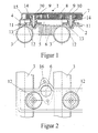
- Air intake duct system 1 the valve position once in the open position and once in the closed position is shown. It should be clear that the Valve positions are aligned in the same way.
- Fig. 1 shows the air intake duct system 1 according to the invention in section.
- the Air intake duct system has an air intake duct housing 2 for the individual leading each cylinder of an internal combustion engine, not shown Air intake ducts 3.
- On the air intake duct housing 2 is known Way, a cover element 4 arranged, for example by screwing. Between the cover element 4 and the air intake duct housing 2 is on this Formed an exhaust gas recirculation channel 5 via an exhaust gas inlet 6 Exhaust gas is supplied.
- a drive mechanism 7 is located on the cover element 4 arranged, which consists of a rack 8 and 9 gears.
- the Gears 9 are in turn connected to shafts 10 which on their Air intake duct housing 2 facing side flat slide elements 11, which in the present case, as can be seen from FIG. 2, as flat rotary slide elements are executed.
- These flat rotary slide elements act with exhaust gas inlet openings 12 and flat seats 13 together and in this way enable one Exhaust gas recirculation into the air intake ducts 3.
- the left valve position is in the open position and the right valve position is shown in the closed position.
- the Flat rotary slide elements 11 are each by a spring 14 which on Cover element 4 supports against the corresponding flat seat 13 below Bias held.
- the drive mechanism 7 is in the present case by a cover 15 is closed.
- Fig. 2 shows a top view of part of the invention Air intake duct system 1. It can be clearly seen here that the Exhaust gas inlet openings 12 in the present case as semicircular ring pieces are executed. Furthermore, the exhaust gas inlet 6 with a connecting flange 16 shown.
Landscapes
- Engineering & Computer Science (AREA)
- Chemical & Material Sciences (AREA)
- Combustion & Propulsion (AREA)
- Mechanical Engineering (AREA)
- General Engineering & Computer Science (AREA)
- Exhaust-Gas Circulating Devices (AREA)
- Mechanically-Actuated Valves (AREA)
- Control Of Throttle Valves Provided In The Intake System Or In The Exhaust System (AREA)
- Characterised By The Charging Evacuation (AREA)
Abstract
Description
- Fig. 1
- eine Schnittansicht eines Teils des erfindungsgemäßen Luftansaugkanalsystems, und
- Fig. 2
- eine Draufsicht des erfindungsgemäßen Luftansaugkanalsystems.
Claims (5)
- Luftansaugkanalsystem für eine Brennkraftmaschine mit einem Luftansaugkanalgehäuse, das einzelne zu jedem Zylinder der Brennkraftmaschine führende Luftansaugkanäle aufweist, mit einem Abgasrückführkanal, dessen Abgasrückführung in die einzelnen Luftansaugkanäle durch jeweils ein Ventilelement steuerbar ist, dadurch gekennzeichnet, daß das Luftansaugkanalsystem (1) ein Deckelelement (4) aufweist, das auf dem Luftansaugkanalgehäuse (2) derart angeordnet ist, daß zwischen dem Deckelelement (4) und dem Luftansaugkanalgehäuse (2) der Abgasrückführkanal (5) ausgeformt ist, wobei das Deckelelement (4) die als Flachschieberelemente (11) ausgeführten Ventilelemente sowie einen Antriebsmechanismus (7) zur Verstellung der Flachschieberelemente (11) aufweist und jeder Luftansaugkanal (3) eine Abgaseinlaßöffnung (12) mit einem Flachsitz (13) aufweist, der mit dem Flachschieberelement (11) zusammenwirkt.
- Luftansaugkanalsystem nach Anspruch 1 oder 2, dadurch gekennzeichnet, daß die Flachschieberelemente (11) als Flachdrehschieberelemente ausgebildet sind, wobei die Abgaseinlaßöffnungen (12) als halbkreisförmige Ringstücke ausgebildet sind.
- Luftansaugkanalsystem nach Anspruch 3, dadurch gekennzeichnet, daß der Antriebsmechanismus (7) aus einem Zahnstange-Zahnrad-Antrieb (8, 9), wobei jedem Flachdrehschieberelement ein Zahnrad (9) zugeordnet ist.
- Luftansaugkanalsystem nach Anspruch 3 oder 4, dadurch gekennzeichnet, daß ein Flachdrehschieberelement (11) durch eine Feder (14) gegenüber dem entsprechenden Flachsitz (13) vorgespannt ist.
- Luftansaugkanalsystem nach einem der vorherigen Ansprüche, dadurch gekennzeichnet, dass ein Antrieb, beispielsweise ein Elektromotor in dem Deckelelement (4) gelagert ist.
Applications Claiming Priority (2)
| Application Number | Priority Date | Filing Date | Title |
|---|---|---|---|
| DE10015210 | 2000-03-27 | ||
| DE10015210A DE10015210A1 (de) | 2000-03-27 | 2000-03-27 | Luftansaugkanlsystem für eine Brennkraftmaschine |
Publications (3)
| Publication Number | Publication Date |
|---|---|
| EP1138926A2 true EP1138926A2 (de) | 2001-10-04 |
| EP1138926A3 EP1138926A3 (de) | 2002-07-17 |
| EP1138926B1 EP1138926B1 (de) | 2003-11-05 |
Family
ID=7636585
Family Applications (1)
| Application Number | Title | Priority Date | Filing Date |
|---|---|---|---|
| EP01104236A Expired - Lifetime EP1138926B1 (de) | 2000-03-27 | 2001-02-22 | Luftansaugkanalsystem für eine Brennkraftmaschine |
Country Status (3)
| Country | Link |
|---|---|
| EP (1) | EP1138926B1 (de) |
| DE (2) | DE10015210A1 (de) |
| ES (1) | ES2204770T3 (de) |
Citations (1)
| Publication number | Priority date | Publication date | Assignee | Title |
|---|---|---|---|---|
| DE19816266A1 (de) | 1998-04-11 | 1999-10-14 | Pierburg Ag | Luftansaugkanalsystem für eine Brennkraftmaschine |
Family Cites Families (4)
| Publication number | Priority date | Publication date | Assignee | Title |
|---|---|---|---|---|
| JP2714770B2 (ja) * | 1995-03-27 | 1998-02-16 | 昭和アルミニウム株式会社 | 吸気マニホルド |
| JPH09273452A (ja) * | 1996-04-09 | 1997-10-21 | Hino Motors Ltd | 排ガス再循環装置 |
| JP3809696B2 (ja) * | 1997-03-25 | 2006-08-16 | 株式会社豊田自動織機 | 内燃機関の排気ガス再循環装置 |
| BR9812326A (pt) * | 1997-09-16 | 2001-12-18 | Mann & Hummel Filter | Dispositivo para recircular gás de exaustão em ummotor de combustão |
-
2000
- 2000-03-27 DE DE10015210A patent/DE10015210A1/de not_active Withdrawn
-
2001
- 2001-02-22 EP EP01104236A patent/EP1138926B1/de not_active Expired - Lifetime
- 2001-02-22 ES ES01104236T patent/ES2204770T3/es not_active Expired - Lifetime
- 2001-02-22 DE DE50100888T patent/DE50100888D1/de not_active Expired - Lifetime
Patent Citations (1)
| Publication number | Priority date | Publication date | Assignee | Title |
|---|---|---|---|---|
| DE19816266A1 (de) | 1998-04-11 | 1999-10-14 | Pierburg Ag | Luftansaugkanalsystem für eine Brennkraftmaschine |
Also Published As
| Publication number | Publication date |
|---|---|
| EP1138926B1 (de) | 2003-11-05 |
| EP1138926A3 (de) | 2002-07-17 |
| DE10015210A1 (de) | 2001-10-04 |
| DE50100888D1 (de) | 2003-12-11 |
| ES2204770T3 (es) | 2004-05-01 |
Similar Documents
| Publication | Publication Date | Title |
|---|---|---|
| EP2102468B1 (de) | Mehrstufige turboladeranordnung | |
| DE19614474B4 (de) | Luftansaugkanalsystem für Brennkraftmaschinen | |
| DE10346250B4 (de) | Abgaskühler mit einem Bypass | |
| DE102005005190A1 (de) | Abgaskühleranordnung für ein Kraftfahrzeug | |
| DE102009008011A1 (de) | Verbrennungsmotor | |
| DE69910269T2 (de) | Brennkraftmaschine mit einer kompakten Ansaugeinrichtung | |
| EP1138926B1 (de) | Luftansaugkanalsystem für eine Brennkraftmaschine | |
| EP1388652B1 (de) | Ansaugkanalsystem | |
| EP1462624B1 (de) | Sekundärluftventil | |
| DE102009012211A1 (de) | Klappenvorrichtung für eine Verbrennungskraftmaschine | |
| DE10101412A1 (de) | Abgasrückführeinrichtung für eine Brennkraftmaschine | |
| EP1508684A1 (de) | Abgaseinleitvorrichtung für eine Brennkraftmaschine | |
| DE69103117T2 (de) | Brennkraftmaschine mit einer Vorrichtung zum Einblasen von Luft in die Abgasanlage. | |
| DE19526241B4 (de) | Lufteinlaßkanalsystem für Brennkraftmaschinen | |
| DE102009057497A1 (de) | Klappenventil zur Einleitung und Steuerung eines Frischluftstromes und eines Abgasrückführstromes | |
| WO2016102256A1 (de) | Ventil zur steuerung eines gasstroms, flüssigkeitsabscheider, entlüftungssystem und verbrennungsmotor mit einem derartigen ventil | |
| EP1020635B1 (de) | Brennluftansaugrohrabschnitt für Dieselbrennkraftmaschinen | |
| DE102004002641A1 (de) | Modulare Ansaugvorrichtung | |
| DE19714311A1 (de) | Luftansaugkanalsystem für Brennkraftmaschinen | |
| DE102017215365B4 (de) | Ölabscheide- und Motorbelüftungseinrichtung | |
| DE102007048301B4 (de) | Ventilanordnung eines Abgasrückführungssystems | |
| AT413864B (de) | Einlasssammler für eine brennkraftmaschine | |
| DE102016211724B4 (de) | AGR-Kühler-Anordnung mit selektiv tätigem Bypassventil | |
| DE102016211725A1 (de) | Ventilanordnung für AGR-Kühler | |
| DE102008009349B4 (de) | Ventil eines Abgasrückführungssystems |
Legal Events
| Date | Code | Title | Description |
|---|---|---|---|
| PUAI | Public reference made under article 153(3) epc to a published international application that has entered the european phase |
Free format text: ORIGINAL CODE: 0009012 |
|
| 17P | Request for examination filed |
Effective date: 20010222 |
|
| AK | Designated contracting states |
Kind code of ref document: A2 Designated state(s): AT BE CH CY DE DK ES FI FR GB GR IE IT LI LU MC NL PT SE TR |
|
| AX | Request for extension of the european patent |
Free format text: AL;LT;LV;MK;RO;SI |
|
| PUAL | Search report despatched |
Free format text: ORIGINAL CODE: 0009013 |
|
| AK | Designated contracting states |
Kind code of ref document: A3 Designated state(s): AT BE CH CY DE DK ES FI FR GB GR IE IT LI LU MC NL PT SE TR |
|
| AX | Request for extension of the european patent |
Free format text: AL;LT;LV;MK;RO;SI |
|
| RAP1 | Party data changed (applicant data changed or rights of an application transferred) |
Owner name: PIERBURG GMBH |
|
| 17Q | First examination report despatched |
Effective date: 20020924 |
|
| AKX | Designation fees paid |
Designated state(s): DE ES FR GB IT |
|
| GRAH | Despatch of communication of intention to grant a patent |
Free format text: ORIGINAL CODE: EPIDOS IGRA |
|
| GRAS | Grant fee paid |
Free format text: ORIGINAL CODE: EPIDOSNIGR3 |
|
| GRAA | (expected) grant |
Free format text: ORIGINAL CODE: 0009210 |
|
| AK | Designated contracting states |
Kind code of ref document: B1 Designated state(s): DE ES FR GB IT |
|
| REG | Reference to a national code |
Ref country code: GB Ref legal event code: FG4D Free format text: NOT ENGLISH |
|
| REF | Corresponds to: |
Ref document number: 50100888 Country of ref document: DE Date of ref document: 20031211 Kind code of ref document: P |
|
| REG | Reference to a national code |
Ref country code: IE Ref legal event code: FG4D Free format text: GERMAN |
|
| PGFP | Annual fee paid to national office [announced via postgrant information from national office to epo] |
Ref country code: FR Payment date: 20040209 Year of fee payment: 4 |
|
| GBT | Gb: translation of ep patent filed (gb section 77(6)(a)/1977) |
Effective date: 20040126 |
|
| REG | Reference to a national code |
Ref country code: ES Ref legal event code: FG2A Ref document number: 2204770 Country of ref document: ES Kind code of ref document: T3 |
|
| REG | Reference to a national code |
Ref country code: IE Ref legal event code: FD4D |
|
| ET | Fr: translation filed | ||
| PLBE | No opposition filed within time limit |
Free format text: ORIGINAL CODE: 0009261 |
|
| STAA | Information on the status of an ep patent application or granted ep patent |
Free format text: STATUS: NO OPPOSITION FILED WITHIN TIME LIMIT |
|
| 26N | No opposition filed |
Effective date: 20040806 |
|
| PG25 | Lapsed in a contracting state [announced via postgrant information from national office to epo] |
Ref country code: IT Free format text: LAPSE BECAUSE OF NON-PAYMENT OF DUE FEES Effective date: 20050222 Ref country code: GB Free format text: LAPSE BECAUSE OF NON-PAYMENT OF DUE FEES Effective date: 20050222 |
|
| GBPC | Gb: european patent ceased through non-payment of renewal fee |
Effective date: 20050222 |
|
| PG25 | Lapsed in a contracting state [announced via postgrant information from national office to epo] |
Ref country code: FR Free format text: LAPSE BECAUSE OF NON-PAYMENT OF DUE FEES Effective date: 20051031 |
|
| REG | Reference to a national code |
Ref country code: FR Ref legal event code: ST Effective date: 20051031 |
|
| PGFP | Annual fee paid to national office [announced via postgrant information from national office to epo] |
Ref country code: ES Payment date: 20060227 Year of fee payment: 6 |
|
| REG | Reference to a national code |
Ref country code: ES Ref legal event code: FD2A Effective date: 20070223 |
|
| PG25 | Lapsed in a contracting state [announced via postgrant information from national office to epo] |
Ref country code: ES Free format text: LAPSE BECAUSE OF NON-PAYMENT OF DUE FEES Effective date: 20070223 |
|
| PGFP | Annual fee paid to national office [announced via postgrant information from national office to epo] |
Ref country code: DE Payment date: 20120419 Year of fee payment: 12 |
|
| REG | Reference to a national code |
Ref country code: DE Ref legal event code: R119 Ref document number: 50100888 Country of ref document: DE Effective date: 20130903 |
|
| PG25 | Lapsed in a contracting state [announced via postgrant information from national office to epo] |
Ref country code: DE Free format text: LAPSE BECAUSE OF NON-PAYMENT OF DUE FEES Effective date: 20130903 |