EP1138555B2 - Dispositif de support et de guidage d'un faisceau de fils électriquement conducteurs permettant de suivre les déplacements d'un siège avant de véhicule automobile - Google Patents
Dispositif de support et de guidage d'un faisceau de fils électriquement conducteurs permettant de suivre les déplacements d'un siège avant de véhicule automobile Download PDFInfo
- Publication number
- EP1138555B2 EP1138555B2 EP01400782.7A EP01400782A EP1138555B2 EP 1138555 B2 EP1138555 B2 EP 1138555B2 EP 01400782 A EP01400782 A EP 01400782A EP 1138555 B2 EP1138555 B2 EP 1138555B2
- Authority
- EP
- European Patent Office
- Prior art keywords
- plate
- bundle
- band
- flexible
- support
- Prior art date
- Legal status (The legal status is an assumption and is not a legal conclusion. Google has not performed a legal analysis and makes no representation as to the accuracy of the status listed.)
- Expired - Lifetime
Links
- 238000006073 displacement reaction Methods 0.000 title description 4
- 239000000463 material Substances 0.000 claims description 8
- 239000004743 Polypropylene Substances 0.000 claims description 3
- -1 polypropylene Polymers 0.000 claims description 3
- 229920001155 polypropylene Polymers 0.000 claims description 3
- 229920003023 plastic Polymers 0.000 claims description 2
- 239000004033 plastic Substances 0.000 claims description 2
- 239000004020 conductor Substances 0.000 description 4
- 229920002457 flexible plastic Polymers 0.000 description 3
- 230000003014 reinforcing effect Effects 0.000 description 3
- 230000002787 reinforcement Effects 0.000 description 2
- 241000909536 Gobiesocidae Species 0.000 description 1
- 239000011324 bead Substances 0.000 description 1
- 238000010438 heat treatment Methods 0.000 description 1
- 238000009434 installation Methods 0.000 description 1
- 238000000465 moulding Methods 0.000 description 1
Images


Classifications
-
- B—PERFORMING OPERATIONS; TRANSPORTING
- B60—VEHICLES IN GENERAL
- B60N—SEATS SPECIALLY ADAPTED FOR VEHICLES; VEHICLE PASSENGER ACCOMMODATION NOT OTHERWISE PROVIDED FOR
- B60N2/00—Seats specially adapted for vehicles; Arrangement or mounting of seats in vehicles
- B60N2/02—Seats specially adapted for vehicles; Arrangement or mounting of seats in vehicles the seat or part thereof being movable, e.g. adjustable
- B60N2/04—Seats specially adapted for vehicles; Arrangement or mounting of seats in vehicles the seat or part thereof being movable, e.g. adjustable the whole seat being movable
- B60N2/06—Seats specially adapted for vehicles; Arrangement or mounting of seats in vehicles the seat or part thereof being movable, e.g. adjustable the whole seat being movable slidable
-
- B—PERFORMING OPERATIONS; TRANSPORTING
- B60—VEHICLES IN GENERAL
- B60N—SEATS SPECIALLY ADAPTED FOR VEHICLES; VEHICLE PASSENGER ACCOMMODATION NOT OTHERWISE PROVIDED FOR
- B60N2/00—Seats specially adapted for vehicles; Arrangement or mounting of seats in vehicles
- B60N2/02—Seats specially adapted for vehicles; Arrangement or mounting of seats in vehicles the seat or part thereof being movable, e.g. adjustable
- B60N2/0224—Non-manual adjustments, e.g. with electrical operation
- B60N2/0244—Non-manual adjustments, e.g. with electrical operation with logic circuits
- B60N2/0264—Non-manual adjustments, e.g. with electrical operation with logic circuits characterised by the type of electrical connection, e.g. wiring, plugs or USB
-
- B—PERFORMING OPERATIONS; TRANSPORTING
- B60—VEHICLES IN GENERAL
- B60N—SEATS SPECIALLY ADAPTED FOR VEHICLES; VEHICLE PASSENGER ACCOMMODATION NOT OTHERWISE PROVIDED FOR
- B60N2/00—Seats specially adapted for vehicles; Arrangement or mounting of seats in vehicles
- B60N2/70—Upholstery springs ; Upholstery
- B60N2/7094—Upholstery springs
-
- B—PERFORMING OPERATIONS; TRANSPORTING
- B60—VEHICLES IN GENERAL
- B60R—VEHICLES, VEHICLE FITTINGS, OR VEHICLE PARTS, NOT OTHERWISE PROVIDED FOR
- B60R16/00—Electric or fluid circuits specially adapted for vehicles and not otherwise provided for; Arrangement of elements of electric or fluid circuits specially adapted for vehicles and not otherwise provided for
- B60R16/02—Electric or fluid circuits specially adapted for vehicles and not otherwise provided for; Arrangement of elements of electric or fluid circuits specially adapted for vehicles and not otherwise provided for electric constitutive elements
- B60R16/0207—Wire harnesses
- B60R16/0215—Protecting, fastening and routing means therefor
-
- H—ELECTRICITY
- H02—GENERATION; CONVERSION OR DISTRIBUTION OF ELECTRIC POWER
- H02G—INSTALLATION OF ELECTRIC CABLES OR LINES, OR OF COMBINED OPTICAL AND ELECTRIC CABLES OR LINES
- H02G11/00—Arrangements of electric cables or lines between relatively-movable parts
- H02G11/006—Arrangements of electric cables or lines between relatively-movable parts using extensible carrier for the cable, e.g. self-coiling spring
Definitions
- the present invention relates to a device for supporting and guiding a bundle of electrically conductive yarns intended in particular for connecting an electrical equipment integral with the seat of a front seat of a motor vehicle to the battery for powering the vehicle. in order to follow the movements, imposed by the occupant, of the seat relative to the floor of the vehicle.
- the front seats of current motor vehicles increasingly include equipment requiring a power supply, such as for example electric motors for adjusting the seat to a position chosen by the occupant, a heating sheet of the seat cushion, an airbag, a non-fastening indicator of the safety belt, an audio compact disc magazine, all generally secured to the seat base in the lower part thereof.
- a power supply such as for example electric motors for adjusting the seat to a position chosen by the occupant, a heating sheet of the seat cushion, an airbag, a non-fastening indicator of the safety belt, an audio compact disc magazine, all generally secured to the seat base in the lower part thereof.
- the harness connecting the battery pack to the seat usually travels at floor level under the carpet placed on it.
- the beam connecting it to the floor has a deformable portion located under the seat. This deformable portion has a generally curved shape and a length allowing the longitudinal and / or vertical movements of the seat.
- the portion of the beam below the seat is usually wrapped to form a compact bead.
- the operation of tape-wrapping the beam remains imprecise and not easy.
- the orientation of the beam under the seat remains random because it, although being wrapped, can twist or get stuck when adjusting the seat position.
- the connectors used to connect the harness of the seat to the harness leading to the battery of the vehicle are generally elements reported at the time of assembly or are already connected to one of the beams to be connected, seat or floor side. These connectors may be disconnected and lost before or during installation.
- FR-A-2,750,265 which represents the state of the art closest, describes a device for guiding an electrical harness between a fixed element and a movable element of a motor vehicle.
- This device is formed by a chain with articulated links, provided with a median channel for passage of electrical harness and U-shaped members locking links between them.
- Each link is formed by an elongated body having, at one of its ends, a ball joint connected to this body by a constriction and, at the other of its ends, a housing opening for receiving the ball joint of the next link .
- This known device is thus an extremely complex embodiment and is therefore expensive.
- the present invention aims to eliminate the above disadvantages of known devices for supporting an electrical harness.
- the document WO 98/40465 and the document US 3473769 also present devices for supporting and guiding a deformable beam of electrically conductive wires.
- the invention proposes a device for supporting and guiding a deformable bundle of electrically conductive wires as defined in claim 1.
- the flexible arched strip is made of a flexible plastic material, such as polypropylene.
- the electrical harness fastening means in the trough of the flexible strip comprise stud fasteners mounted articulated at regular intervals on one of the walls of the chute and snap-fastened at their free ends on the other side wall of the flexible band.
- the device further comprises a fixing means for fixing to the plate the end portion of the electrical harness located in the vicinity of the junction zone between the flexible strip and the plate.
- this fastening means is a clamping collar.
- the flexible band comprises at least one hook or clip for fixing the upper end of the flexible band by snapping this end to the movable part.
- the plate comprises means for positioning and fixing the support and constituted in particular by one or more positioning bars and one or more fixing pins capable of forcibly engaging in conjugally shaped openings of the support.
- the plate further comprises at least one electrical connector attached thereto and allowing the connection of the conductors son of the beam.
- the device comprises spacing means provided on the plate, for forming a space between the plate and the support for receiving therein one or more electrical connectors fixed under the plate and allowing the connection of the conductive wires of an electrical harness leading to the power source.
- the device for supporting and guiding a bundle of electrically conductive wires according to the invention will be described in application to a front seat of a motor vehicle.
- the reference 1 designates a frame member of the seat of a front seat (not shown) of a motor vehicle and intended to support the occupant of the seat.
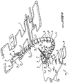
- the device of the invention is located under the reinforcing element 1 and is arranged to support and guide a deformable beam of electrically conductive wires 2, visible in figure 1 , to enable this beam to follow the movements of the reinforcement element 1 of the seat such as a longitudinal displacement to the vehicle in front of or behind it, a vertical displacement relative to the floor 3 of the vehicle, see even a slight rotation around a vertical axis perpendicular to this floor.
- the electrical harness 2 is designed to electrically connect an equipment secured to the seat, for example the reinforcing element 1, such as for example an electric motor for adjusting the seat position to the vehicle battery.
- This device comprises an elongated and arched flexible strip 4 located under the armature element 1 being disposed in a plane approximately vertical to the floor 3 of the vehicle.
- the flexible strip 4 may be made of a flexible plastic material, such as polypropylene, and comprise a plurality of elements 5 joined to each other by smaller transverse zones 6 constituting film hinges so as to allow a deformation of the strip 4 towards the front or rear of the vehicle and / or upwards and downwards with respect to the floor 3.
- a flexible plastic material such as polypropylene
- the flexible strip 4 is similar to a caterpillar portion.
- the flexible band 4 has its upper end fixed to the reinforcing element 1 by at least one folded portion 7 secured to the dorsal side of the band 4 and forming a snap hook or fastening clip to a straight portion of the rod 1 of the reinforcement element 1.
- the end of the band 4 comprises two attachment parts 7 located in extension of one another to snap respectively on two parallel straight portions of rod 1a as shown in FIG. figure 2 .
- This last figure shows that the end of the strip 4 may comprise a third attachment portion 7 snap-fastened to a rod portion connecting the two parallel portions perpendicular to them.
- the lower end of the flexible band 4 is secured to a plate 8 fixed to the floor 3.
- the end portion of the band 4 fixed to the plate 8 comprises a housing 9 secured to the plate 8 and in which is housed in part the electrical harness 2 which passes through the housing 9 protruding therefrom forming before forming a baffle deformation.
- the portion of the harness 2 can be fixed in the housing 9 by a clamping collar 10 of flexible plastic material and the housing is closed by a cover 11 mounted hinged to one of the side walls of the housing 9 by two hinges 12 films coming from of material with two vertical plates 13 of the housing 9.
- the cover 11 is locked by blades 14 integral with the latter and whose ends are configured to snap respectively on fixing feet 15 secured to the plate 8 perpendicular to that and adjacent to the side wall of the housing 9 opposite to the two wall elements 13.
- the cover 11 has an opening 11a allowing the free passage of the clamp 10 when the latter firmly holds the part of the beam 2 in the housing 9 and that the cover 11 is folded in the locked position on this housing.
- the flexible strip 4 is in the form of a chute in which is fixed the electric harness 2 which is in intimate contact with the inner face of the strip 4 all along thereof.
- the side walls of the beam housing chute 2 are constituted by small plates 16 extending at regular intervals along the two edges of the strip 4 projecting radially inwardly thereof, that is, to say of its internal face as opposed to its dorsal face having the attachment portions 7.
- the harness 2 is trapped and held firmly in the chute defined by the transverse plates 16 by fasteners 17 forming crampons mounted articulated at regular intervals on some of the transverse plates 16 located on the same side of the flexible strip 4 and whose ends free ends are shaped to allow snap fastening of the fasteners 17 on the transverse plates vis-à-vis 16 located on the other side of the strip 4.
- Each fastener 17 can be hinged to the corresponding transverse plate 16 by a hinge film From the material with the plate 16. In this way, the electrical harness 2 is maintained in the channel of the strip 4 without being able to leave it during longitudinal and / or vertical displacements of the seat cushion.
- the flexible strip 4 and the transverse plates 16, the attachment parts 7, the fasteners 17 and the housing 9 can be made in one piece by molding a plastic material.
- This flexible material of the band 4 can be slightly twisted to allow a slight rotation of the seat around a vertical axis or for a catch of the games between the various positioning elements of the seat relative to the floor 3.
- the plate 8 is provided with positioning means relative to the floor 3 and comprising a tongue 18 of lesser thickness than the plate 8 located in a plane below the plane of the plate to engage under the carpet of the vehicle disposed on the floor 3, one or more bar-shaped positioning members 19 extending vertically above the plate 8 to position themselves under the slide of the seat and one or more centering pins 20 protruding from below the plate 8 to engage respectively in openings of the combined shape of the floor 3.
- the plate 8 further comprises means for fixing the floor 3 and constituted by one or more ridged pins 21 called fir tree engaging elastically in openings conjugates of the floor 3.
- the plate 8 may include fastening means, such as openings 22, adapted to receive one or more electrical connectors mounted on the plate 8 for the connection of the conductors son of the beam 2 coming out of the housing 9.
- the plate 8 fixed to the floor 3 can define relative to it a space in which connectors can be arranged under the plate 8 and for connecting the conductors son of a harness (not shown) leading to the vehicle battery.
- This space may be in the form of an arcuate or U-shaped cross-section cup made in the floor 3.
- the electrical interconnection of the connection connector (s) of the bundle 2 and the connection connector (s) of the bundle leading to the battery can be ensured. by conductive tracks engraved on the plate 8 or embedded therein.
- the mounting of the support device and guide of the invention is as follows. First, before mounting the seat in the passenger compartment of the vehicle, the flexible strip 4 is fixed by the attachment means 7 to the frame member 1 of the seat of this seat. Then, the electrical harness 2 is positioned in the housing of the duct slot 4 and the fasteners 17 are folded to be locked by snapping to the corresponding transverse plates 16 of the strip 4 to trap the beam 2 in the chute. The collar 10 is then tightened to firmly hold the beam portion 2 in the housing 9 which is an area subject to significant effort and likely to leave the beam of its housing. The electrical connectors are then mounted on the plate 8 and the conductor son of the beam 2 integral with the flexible band 4 are connected to the corresponding inputs of these connectors.
- the seat is then mounted in the vehicle, in the tilted position forward supported on a front portion of the seat and the leads of the beam leading to the battery are connected to the corresponding inputs of the connectors fixed under the plate 8 which is then positioned on the floor 3 and attached thereto.
- the device according to the invention is shaped so as to support, maintain and protect the portion of the electrically conductive wire bundle located under the seat and guide this beam portion during longitudinal and / or vertical movements of the seat.
- This device also supports connectors for connecting the harness secured to the seat to the harness leading to the battery.
Landscapes
- Engineering & Computer Science (AREA)
- Mechanical Engineering (AREA)
- Aviation & Aerospace Engineering (AREA)
- Transportation (AREA)
- Seats For Vehicles (AREA)
- Current-Collector Devices For Electrically Propelled Vehicles (AREA)
- Installation Of Indoor Wiring (AREA)
Description
- La présente invention concerne un dispositif de support et de guidage d'un faisceau de fils électriquement conducteurs destiné en particulier à relier un équipement électrique solidaire de l'assise d'un siège avant d'un véhicule automobile à la batterie d'alimentation du véhicule de façon à suivre les déplacements, imposés par l'occupant, du siège relativement au plancher du véhicule.
- Les sièges avant des véhicules automobiles actuels comportent de plus en plus des équipements nécessitant une alimentation électrique, tels que par exemple des moteurs électriques pour le réglage du siège à une position choisie par l'occupant, une nappe chauffante de l'assise du siège, un sac gonflable de sécurité, un témoin de non bouclage de la ceinture de sécurité, un chargeur de disques compacts audio, tous généralement solidaires de l'assise du siège en partie inférieure de celle-ci.
- Le faisceau électrique reliant la batterie d'alimentation au siège chemine généralement au niveau du plancher sous la moquette posée sur celui-ci. Pour suivre les déplacements du siège, le faisceau reliant celui-ci au plancher comporte une portion déformable située sous le siège. Cette portion déformable a une forme généralement courbée et une longueur permettant les déplacements longitudinaux et/ou verticaux du siège.
- Afin de limiter les risques d'accrochage du faisceau avec un élément voisin, tel que par exemple le pied d'un passager situé derrière le siège avant, la portion du faisceau en dessous du siège est généralement enrubannée pour former un cordon compact. Cependant, l'opération consistant à enrubanner par un ruban adhésif le faisceau reste imprécise et peu aisée.
- En outre, l'orientation du faisceau sous le siège reste aléatoire car celui-ci, bien qu'étant enrubanné, peut se vriller ou se coincer lors du réglage de la position du siège.
- Par ailleurs, les connecteurs utilisés pour relier le faisceau solidaire du siège au faisceau menant à la batterie du véhicule sont généralement des éléments rapportés au moment du montage ou sont déjà branchés à l'un des faisceaux à connecter, côté siège ou côté plancher. Ces connecteurs risquent donc de se débrancher et de se perdre avant le montage ou pendant celui-ci.
-
FR-A-2 750 265 - Ce dispositif connu est ainsi d'une réalisation extrêmement complexe et est par conséquent coûteux.
- La présente invention a pour but d'éliminer les inconvénients ci-dessus des dispositifs connus de support d'un faisceau électrique.
- Le document
WO 98/40465 US 3473769 présentent aussi des dispositifs de support et de guidage d'un faisceau déformable de fils électriquement conducteurs. - A cet effet, l'invention propose un dispositif de support et de guidage d'un faisceau déformable de fils électriquement conducteurs tel que défini dans la revendication 1.
- Avantageusement, la bande flexible cambrée est réalisée en une matière plastique souple, telle que du polypropylène.
- De préférence, les moyens de fixation du faisceau électrique dans la goulotte de la bande flexible comprennent des attaches formant crampons montées articulées à intervalles réguliers sur l'une des parois de la goulotte et fixées par encliquetage à leurs extrémités libres sur l'autre paroi latérale de la bande flexible.
- Le dispositif comprend en outre un moyen de fixation permettant de fixer à la platine la partie d'extrémité du faisceau électrique située au voisinage de la zone de jonction entre la bande flexible et la platine.
- Avantageusement, ce moyen de fixation est un collier de serrage.
- La bande flexible comprend au moins un crochet ou agrafe permettant de fixer l'extrémité supérieure de la bande flexible par encliquetage de cette extrémité à la partie mobile.
- La platine comprend des moyens de positionnement et de fixation au support et constitués notamment par une ou plusieurs barrettes de positionnement et un ou plusieurs pions de fixation aptes à s'engager à force dans des ouvertures de forme conjuguée du support.
- La platine comprend en outre au moins un connecteur électrique fixé sur celle-ci et permettant le branchement des fils conducteurs du faisceau.
- Avantageusement, le dispositif comprend des moyens d'espacement prévus sur la platine, permettant de former un espace entre la platine et le support pour recevoir dans celui-ci un ou plusieurs connecteurs électriques fixés sous la platine et permettant le branchement des fils conducteurs d'un faisceau électrique menant à la source d'alimentation.
- L'invention sera mieux comprise et d'autres buts, caractéristiques, détails et avantages de celle-ci apparaîtront plus clairement dans la description explicative qui va suivre faite en référence aux dessins annexés donnés uniquement à titre d'exemple illustrant un mode de réalisation de l'invention et dans lesquels :
- la
figure 1 est une vue en perspective du dispositif de support et de guidage d'un faisceau électrique conforme à l'invention ; - la
figure 2 représente le dispositif de lafigure 1 appliqué à un siège avant de véhicule automobile ; et - la
figure 3 est une vue en perspective de dessous suivant la flèche III du dispositif de lafigure 2 . - Le dispositif de support et de guidage d'un faisceau de fils électriquement conducteurs conforme à l'invention va être décrit en application à un siège avant de véhicule automobile.
- En se reportant aux figures, la référence 1 désigne un élément d'armature de l'assise d'un siège avant (non représenté) de véhicule automobile et destiné à supporter l'occupant du siège.
- Le dispositif de l'invention est situé sous l'élément d'armature 1 et est agencé de façon à supporter et guider un faisceau déformable de fils électriquement conducteurs 2, visible en
figure 1 , pour permettre à ce faisceau de suivre les déplacements de l'élément d'armature 1 de l'assise tels qu'un déplacement longitudinal au véhicule en avant ou en arrière de celui-ci, un déplacement vertical relativement au plancher 3 du véhicule, voir même une légère rotation autour d'un axe vertical perpendiculaire à ce plancher. - Le faisceau électrique 2 est conçu pour relier électriquement un équipement solidaire de l'assise, par exemple de l'élément d'armature 1, tel que par exemple un moteur électrique permettant le réglage en position du siège, à la batterie du véhicule.
- Ce dispositif comprend une bande flexible allongée et cambrée 4 située sous l'élément d'armature 1 en étant disposée dans un plan approximativement vertical au plancher 3 du véhicule.
- La bande flexible 4 peut être réalisée en une matière plastique souple, telle que du polypropylène, et comprendre une pluralité d'éléments 5 liés les uns aux autres par des zones transversales de moindre épaisseur 6 constituant des charnières films de façon à permettre une déformation de la bande 4 vers l'avant ou l'arrière du véhicule et/ou vers le haut et le bas par rapport au plancher 3.
- La bande flexible 4 s'apparente à une portion de chenille.
- La bande flexible 4 a son extrémité supérieure fixée à l'élément d'armature 1 par au moins une partie repliée 7 solidaire de la face dorsale de bande 4 et formant crochet ou agrafe de fixation par encliquetage à une portion droite de tige la de l'élément d'armature 1. Comme représenté en
figure 1 , l'extrémité de la bande 4 comporte deux parties d'accrochage 7 situées en prolongement l'une de l'autre pour s'encliqueter respectivement sur deux parties droites parallèles de tige la comme représenté enfigure 2 . Cette dernière figure montre que l'extrémité de la bande 4 peut comporter une troisième partie d'accrochage 7 fixée par encliquetage à une portion de tige la raccordant les deux portions parallèles la perpendiculairement à celles-ci. - L'extrémité inférieure de la bande flexible 4 est solidaire d'une platine 8 fixée au plancher 3. A cet effet, la partie d'extrémité de la bande 4 fixée à la platine 8 comporte un boîtier 9 solidaire de la platine 8 et dans lequel est logé en partie le faisceau électrique 2 qui traverse le boîtier 9 en faisant saillie de celui-ci en formant avant sa sortie une déformation en chicane.
- La partie du faisceau électrique 2 peut être fixée dans le boîtier 9 par un collier de serrage 10 en matière plastique souple et le boîtier est fermé par un couvercle 11 monté articulé à l'une des parois latérales du boîtier 9 par deux charnières films 12 venant de matière avec deux plaques verticales 13 du boîtier 9. Le couvercle 11 est verrouillé par des lames 14 solidaires de celui-ci et dont les extrémités sont configurées pour s'encliqueter respectivement sur des pieds de fixation 15 solidaires de la platine 8 perpendiculairement à celle-ci et adjacents à la paroi latérale du boîtier 9 opposée aux deux éléments de paroi 13. Le couvercle 11 comporte une ouverture 11a permettant le libre passage du collier de serrage 10 lorsque ce dernier maintient fermement la partie du faisceau 2 dans le boîtier 9 et que le couvercle 11 est rabattu en position verrouillée sur ce boîtier.
- La bande flexible 4 est en forme de goulotte dans laquelle est fixé le faisceau électrique 2 qui est en contact intime avec la face interne de la bande 4 tout le long de celle-ci. Les parois latérales de la goulotte de logement du faisceau 2 sont constituées par de petites plaques 16 s'étendant à intervalles réguliers le long des deux bords de la bande 4 en faisant saillie radialement vers l'intérieur de celle-ci, c'est-à-dire de sa face interne par opposition à sa face dorsale comportant les parties d'accrochage 7.
- Le faisceau électrique 2 est emprisonné et maintenu fermement dans la goulotte définie par les plaques transversales 16 par des attaches 17 formant crampons montées articulées à intervalles réguliers sur certaines des plaques transversales 16 situées d'un même côté de la bande flexible 4 et dont les extrémités libres sont conformées pour permettre la fixation par encliquetage des attaches 17 sur les plaques transversales en vis-à-vis 16 situées de l'autre côté de la bande 4. Chaque attache 17 peut être articulée à la plaque transversale correspondante 16 par une charnière film venant de matière avec la plaque 16. De la sorte, le faisceau électrique 2 est maintenu dans la goulotte de la bande 4 sans pouvoir sortir de celle-ci lors des déplacements longitudinaux et/ou verticaux de l'assise du siège.
- La bande flexible 4 et les plaques transversales 16, les parties d'accrochage 7, les attaches 17 et le boîtier 9 peuvent être réalisés en une seule pièce par moulage d'une matière plastique. Cette matière souple de la bande 4 peut être légèrement vrillée pour autoriser une légère rotation du siège autour d'un axe vertical ou pour un rattrapage des jeux entre les différents éléments de positionnement du siège par rapport au plancher 3.
- La platine 8 est pourvue de moyens de positionnement relativement au plancher 3 et comprenant une languette 18 de moindre épaisseur que la platine 8 située dans un plan en-dessous du plan de la platine pour s'engager sous la moquette du véhicule disposée sur le plancher 3, un ou plusieurs éléments de positionnement 19 en forme de barrette s'étendant verticalement au-dessus de la platine 8 pour se positionner sous la glissière du siège et un ou plusieurs pions de centrage 20 faisant saillie d'en-dessous de la platine 8 pour s'engager respectivement dans des ouvertures de forme conjuguée du plancher 3. La platine 8 comprend en outre des moyens de fixation au plancher 3 et constitués par un ou plusieurs pions striés 21 dits en sapin s'engageant à force élastiquement dans des ouvertures conjuguées du plancher 3.
- La platine 8 peut comporter des moyens de fixation, tels que des ouvertures 22, aptes à recevoir un ou plusieurs connecteurs électriques montés sur la platine 8 pour le branchement des fils conducteurs du faisceau 2 sortant du boîtier 9. La platine 8 fixée au plancher 3 peut définir relativement à celui-ci un espace dans lequel des connecteurs peuvent être disposés sous la platine 8 et permettant de brancher les fils conducteurs d'un faisceau électrique (non représenté) menant à la batterie d'alimentation du véhicule. Cet espace peut être en forme de cuvette à section transversale arquée ou en U réalisée dans le plancher 3. L'interconnexion électrique du ou des connecteurs de branchement du faisceau 2 et du ou des connecteurs de branchement du faisceau menant à la batterie peut être assurée par des pistes conductrices gravées à la platine 8 ou noyées dans celle-ci.
- Le montage du dispositif de support et de guidage de l'invention s'effectue comme suit. Tout d'abord, avant le montage du siège dans l'habitacle du véhicule, la bande flexible 4 est fixée par les moyens d'accrochage 7 à l'élément d'armature 1 de l'assise de ce siège. Ensuite, le faisceau électrique 2 est positionné dans la goulotte de logement de la bande 4 et les attaches 17 sont rabattues pour être verrouillées par encliquetage aux plaques transversales correspondantes 16 de la bande 4 pour emprisonner le faisceau 2 dans la goulotte. Le collier 10 est alors serré pour maintenir fermement la partie de faisceau 2 dans le boîtier 9 qui est une zone sujette à des efforts importants et susceptibles de sortir le faisceau de son logement. Les connecteurs électriques sont alors montés sur la platine 8 et les fils conducteurs du faisceau 2 solidaires de la bande souple 4 sont reliés aux entrées correspondantes de ces connecteurs. Le siège est ensuite monté dans le véhicule, en position basculée vers l'avant en appui sur une partie avant de l'assise et les fils conducteurs du faisceau menant à la batterie sont reliés aux entrées correspondantes des connecteurs fixés sous la platine 8 qui est alors positionnée sur le plancher 3 et fixée à celui-ci.
- Le dispositif conforme à l'invention est conformé de façon à supporter, maintenir et protéger la portion du faisceau à fils électriquement conducteurs située sous le siège et guider cette portion de faisceau lors des déplacements longitudinaux et/ou verticaux du siège. Ce dispositif supporte en outre les connecteurs permettant de relier le faisceau électrique solidaire du siège au faisceau électrique menant à la batterie.
Claims (9)
- Dispositif de support et de guidage d'un faisceau déformable de fils électriquement conducteurs (2) permettant de relier une batterie d'alimentation d'un véhicule automobile à un équipement alimenté par la batterie d'alimentation et solidaire d'une partie mobile, qui est l'assise d'un siège avant de véhicule automobile, relativement à un support (3), qui est le plancher du véhicule, le dispositif de suport comprenant une bande flexible cambrée (4) ayant la forme d'une goulotte pour le logement du faisceau de fils, située sous la partie mobile (1) dans un plan approximativement vertical au support (3) et ayant son extrémité inférieure solidaire d'une platine (8) apte à être fixée au support (3) et son extrémité supérieure comprend un moyen (7) permettant de la fixer à la partie mobile (1) et comprenant des moyens de fixation (17) permettant d'emprisonner le faisceau (2) dans la goulotte en contact intime à la face interne de la bande flexible cambrée (4), de façon à permettre au faisceau (2) de suivre les déformations de la bande flexible cambrée (4) résultant des déplacements de la partie mobile (1) au moins dans deux directions orthogonales respectivement perpendiculaires au support (3) et parallèle à celui-ci, la bande flexible cambrée (4) comprenant une pluralité d'éléments (5) liés les uns aux autres par des zones transversales de moindre épaisseur (6) constituant des charnières films caractérisé en ce que la goulotte a ses parois latérales définies par de petites plaques (16) transversales respectivement aux bords de la bande flexible (4) en s'étendant à intervalles réguliers le long des deux bords de la bande flexible (4) en faisant saillie radialement vers l'intérieur de celle-ci.
- Dispositif selon la revendication 1, caractérisé en ce que la bande flexible cambrée (4) est réalisée en une matière plastique souple, telle que du polypropylène.
- Dispositif selon l'une des revendications précédentes, caractérisé en ce que les moyens de fixation (17) comprennent des attaches formant crampons montées articulées à Intervalles réguliers sur l'une des parois de la goulotte de la bande flexible (4) et fixées par encliquetage à leurs extrémités libres sur l'autre paroi latérale de la bande flexible (4).
- Dispositif selon l'une des revendications précédentes, caractérisé en ce qu'il comprend un moyen de fixation (10) permettant de fixer à la platine (8) la partie d'extrémité du faisceau (2) située au voisinage de la zone de jonction (9) entre la bande flexible (4) et la platine (8).
- Dispositif selon la revendication 4 caractérisé en ce que ledit moyen de fixation (10) est un collier de serrage.
- Dispositif selon l'une des revendications précédentes, caractérisé en ce que ledit moyen (7) comprend au moins un crochet ou agrafe permettant de fixer l'extrémité supérieure de la bande flexible (4) par encliquetage de cette extrémité à la partie mobile (1).
- Dispositif selon l'une des revendications précédentes, caractérisé en ce que la platine (8) comprend des moyens de positionnement et de fixation au support (3) et constitués notamment par une ou plusieurs barrettes de positionnement (19) et un ou plusieurs pions de fixation (21) aptes à s'engager à force dans des ouvertures de forme conjuguée du support (3).
- Dispositif selon l'une des revendications précédentes, caractérisé en ce que la platine (8) comprend au moins un connecteur électrique fixé sur celle-ci et permettant le branchement des fils conducteurs du faisceau (2).
- Dispositif selon l'une des revendications précédentes, caractérisé en ce qu'il comprend des moyens d'espacement prévus sur la platine (8), permettant de former un espace entre la platine (8) et le support (3) pour recevoir dans celui-ci un ou plusieurs connecteurs électriques fixés sous la platine (8) et permettant le branchement des fils conducteurs d'un faisceau électrique menant à la source d'alimentation.
Priority Applications (1)
| Application Number | Priority Date | Filing Date | Title |
|---|---|---|---|
| DE60107000.3T DE60107000T3 (de) | 2000-03-28 | 2001-03-27 | Vorrichtung zum Tragen und Führen eines Bündels elektrischer Leiter, welche das Folgen von Bewegungen eines Vordersitzes eines Kraftfahrzeugs gestatten |
Applications Claiming Priority (2)
| Application Number | Priority Date | Filing Date | Title |
|---|---|---|---|
| FR0003907 | 2000-03-28 | ||
| FR0003907A FR2807229B1 (fr) | 2000-03-28 | 2000-03-28 | Dispositif de support et de guidage d'un faisceau de fils electriquement conducteurs permettant de suivre les deplacements d'un siege avant de vehicule automobile |
Publications (4)
| Publication Number | Publication Date |
|---|---|
| EP1138555A2 EP1138555A2 (fr) | 2001-10-04 |
| EP1138555A3 EP1138555A3 (fr) | 2002-07-24 |
| EP1138555B1 EP1138555B1 (fr) | 2004-11-10 |
| EP1138555B2 true EP1138555B2 (fr) | 2017-01-25 |
Family
ID=8848570
Family Applications (1)
| Application Number | Title | Priority Date | Filing Date |
|---|---|---|---|
| EP01400782.7A Expired - Lifetime EP1138555B2 (fr) | 2000-03-28 | 2001-03-27 | Dispositif de support et de guidage d'un faisceau de fils électriquement conducteurs permettant de suivre les déplacements d'un siège avant de véhicule automobile |
Country Status (5)
| Country | Link |
|---|---|
| EP (1) | EP1138555B2 (fr) |
| AT (1) | ATE281955T1 (fr) |
| DE (1) | DE60107000T3 (fr) |
| ES (1) | ES2231400T3 (fr) |
| FR (1) | FR2807229B1 (fr) |
Families Citing this family (17)
| Publication number | Priority date | Publication date | Assignee | Title |
|---|---|---|---|---|
| JP3949432B2 (ja) * | 2001-11-14 | 2007-07-25 | 矢崎総業株式会社 | ハーネス弛み吸収装置 |
| FR2859046B1 (fr) * | 2003-08-21 | 2005-10-21 | Renault Sa | Agencement pour le raccordement electrique d'un element d'amenagement interieur |
| US7718894B2 (en) * | 2003-10-15 | 2010-05-18 | Igus Gmbh | Line guide device |
| DE202004005848U1 (de) * | 2003-10-15 | 2005-02-24 | Igus Spritzgussteile für die Industrie GmbH | Leitungsführungseinrichtung |
| DE202004005800U1 (de) | 2004-04-08 | 2005-08-25 | Igus Gmbh | Energieführungskette |
| US20060202526A1 (en) | 2005-03-08 | 2006-09-14 | Stephan Achs | Vehicle seat, especially a motor vehicle seat |
| FR2883423B1 (fr) * | 2005-03-16 | 2007-04-20 | Renault Sas | Raccordement electrique d'un element d'amenagement interieur d'un vehicule automobile |
| DE102007004989B4 (de) * | 2007-02-01 | 2016-12-01 | Jungheinrich Aktiengesellschaft | Verbindungskabel zwischen einer Batterie und einem Antriebsmotor eines Flurförderzeugs |
| FR2924390B1 (fr) | 2007-12-03 | 2010-02-26 | Renault Sas | Raccordement electrique d'un element d'amenagement interieur d'un vehicule automobile |
| DE102008007071B4 (de) * | 2008-01-31 | 2017-03-23 | Murrplastik Systemtechnik Gmbh | Leitungsführungsanordnung |
| DE102008027869A1 (de) * | 2008-06-11 | 2009-12-17 | Dr.Ing.H.C.F.Porsche Aktiengesellschaft | Kabelführungssystem |
| CN102576993B (zh) * | 2010-05-17 | 2015-04-22 | 矢崎总业株式会社 | 电线的布线结构 |
| DE202013105149U1 (de) | 2013-11-14 | 2013-11-27 | Igus Gmbh | Leitungsführung |
| DE202014101366U1 (de) | 2014-03-24 | 2014-03-28 | Igus Gmbh | Leitungsführungseinrichtung mit einstückigem Gelenk, entsprechendes Kettenglied und Gelenkband |
| DE202014101546U1 (de) | 2014-04-01 | 2014-05-26 | Igus Gmbh | Strangartige Leitungsführungseinrichtung, insbesondere für Kapillarröhrchen oder dergleichen |
| US10286813B1 (en) | 2018-01-16 | 2019-05-14 | Ford Global Technologies, Llc | Forward member and harness engagement element to manipulate wiring harness between underside of a seat and floor of a vehicle |
| FR3167780A1 (fr) * | 2024-10-17 | 2026-04-24 | Stellantis Auto Sas | Dispositif de guidage et de maintien d’un câble monté en aveugle |
Family Cites Families (6)
| Publication number | Priority date | Publication date | Assignee | Title |
|---|---|---|---|---|
| DE9016870U1 (de) * | 1990-12-13 | 1992-04-16 | W.L. Gore & Associates Gmbh, 8011 Putzbrunn | Leitungsführungsanordnung |
| EP0544027B1 (fr) * | 1991-11-26 | 1997-03-05 | W.L. Gore & Associates GmbH | Remplacement pour chaines de guidage pour câbles |
| US5292178A (en) * | 1992-07-15 | 1994-03-08 | General Motors Corporation | Front seat for two-door vehicle |
| FR2750265B1 (fr) * | 1996-06-24 | 1998-09-04 | Peugeot | Dispositif de guidage d'au moins un faisceau electrique |
| US6011318A (en) * | 1998-04-16 | 2000-01-04 | Lear Automotive Dearborn, Inc. | Wire harness for vehicle seat |
| DE19837231A1 (de) * | 1998-08-17 | 2000-02-24 | Kabelschlepp Gmbh | Leitungsführungsanordnung |
-
2000
- 2000-03-28 FR FR0003907A patent/FR2807229B1/fr not_active Expired - Fee Related
-
2001
- 2001-03-27 DE DE60107000.3T patent/DE60107000T3/de not_active Expired - Lifetime
- 2001-03-27 EP EP01400782.7A patent/EP1138555B2/fr not_active Expired - Lifetime
- 2001-03-27 ES ES01400782T patent/ES2231400T3/es not_active Expired - Lifetime
- 2001-03-27 AT AT01400782T patent/ATE281955T1/de not_active IP Right Cessation
Also Published As
| Publication number | Publication date |
|---|---|
| EP1138555A3 (fr) | 2002-07-24 |
| DE60107000T2 (de) | 2005-12-01 |
| DE60107000D1 (de) | 2004-12-16 |
| ES2231400T3 (es) | 2005-05-16 |
| EP1138555A2 (fr) | 2001-10-04 |
| EP1138555B1 (fr) | 2004-11-10 |
| DE60107000T3 (de) | 2017-06-22 |
| FR2807229A1 (fr) | 2001-10-05 |
| FR2807229B1 (fr) | 2002-06-28 |
| ATE281955T1 (de) | 2004-11-15 |
Similar Documents
| Publication | Publication Date | Title |
|---|---|---|
| EP1138555B1 (fr) | Dispositif de support et de guidage d'un faisceau de fils électriquement conducteurs permettant de suivre les déplacements d'un siège avant de véhicule automobile | |
| EP2115837B1 (fr) | Dispositif de fixation pour chemin de cables en fils | |
| FR2545996A1 (fr) | Bagues de protection pour lignes a hautes tension | |
| FR2963495A1 (fr) | Couvre fil, procede de cablage de fil et connecteur electrique | |
| EP0284488B1 (fr) | Faisceau électrique de véhicule automobile | |
| FR2783976A1 (fr) | Connecteur electrique muni d'un dispositif de verrouillage empechant un detachament involontaire | |
| FR2579693A1 (fr) | Goujon a souder et agrafe se montant sur ce goujon | |
| EP0191667A1 (fr) | Chemin de câble en treillis | |
| FR2731496A1 (fr) | Dispositif de raccordement d'angle pour conduit a corps en gouttiere et couvercle tel que moulure, plinthe ou goulotte, notamment pour appareillage electrique | |
| EP0744088B1 (fr) | Fiche electrique du type fiche anglaise | |
| FR2922691A1 (fr) | Agrafe pour le maintien de cables ou faisceaux, notamment sur la caisse ou la carrosserie d'un vehicule automobile. | |
| FR2924391A3 (fr) | Raccordement electrique d'un element d'amenagement interieur d'un vehicule automobile | |
| FR2973755A1 (fr) | Dispositif et procede de montage d'un mecanisme d'essuie-vitre | |
| FR2650545A1 (fr) | Boitier de verrouillage pour systeme de ceinture de securite de vehicule | |
| FR3072153B1 (fr) | Dispositif de fixation d'un cordon a une paroi | |
| EP1359653B1 (fr) | Elément constitutif d'une goulotte avec agrafes de retenue de câbles intégrées et goulotte comprenant un ou plusieurs éléments constitutifs de ce type | |
| FR2863217A1 (fr) | Dispositif de fixation d'un coussin d'un siege arriere dans un vehicule automobile | |
| EP0056534A1 (fr) | Pare-chocs pour chariot destiné à recevoir des marchandises diverses, notamment dans les magasins à grande surface | |
| WO2019135036A1 (fr) | Structure de support d'un element adapte pour etre fixe sur un pied avant d'un vehicule | |
| FR2684531A1 (fr) | Systeme de rappel d'une coiffre pour coussin, procede d'assemblage et moyens pour la mise en óoeuvre. | |
| FR2706092A1 (fr) | Dispositif de liaison électrique entre un poste de radio et ses différents équipements et accessoires. | |
| FR3119212A1 (fr) | Agrafe d’attache pour le montage d’un élément allongé sur un support | |
| EP2177398A1 (fr) | Feu de signalisation arrière pour véhicule automobile | |
| WO2018138422A1 (fr) | Systeme de fixation decablessur une barre conductrice rigide | |
| EP1170159A1 (fr) | Elément d'aménagement intérieur d'un habitacle de véhicule automobile |
Legal Events
| Date | Code | Title | Description |
|---|---|---|---|
| PUAI | Public reference made under article 153(3) epc to a published international application that has entered the european phase |
Free format text: ORIGINAL CODE: 0009012 |
|
| AK | Designated contracting states |
Kind code of ref document: A2 Designated state(s): AT BE CH CY DE DK ES FI FR GB GR IE IT LI LU MC NL PT SE TR |
|
| AX | Request for extension of the european patent |
Free format text: AL;LT;LV;MK;RO;SI |
|
| PUAL | Search report despatched |
Free format text: ORIGINAL CODE: 0009013 |
|
| AK | Designated contracting states |
Kind code of ref document: A3 Designated state(s): AT BE CH CY DE DK ES FI FR GB GR IE IT LI LU MC NL PT SE TR |
|
| AX | Request for extension of the european patent |
Free format text: AL;LT;LV;MK;RO;SI |
|
| 17P | Request for examination filed |
Effective date: 20030108 |
|
| AKX | Designation fees paid |
Designated state(s): AT BE CH CY DE DK ES FI FR GB GR IE IT LI LU MC NL PT SE TR |
|
| 17Q | First examination report despatched |
Effective date: 20030627 |
|
| GRAP | Despatch of communication of intention to grant a patent |
Free format text: ORIGINAL CODE: EPIDOSNIGR1 |
|
| GRAS | Grant fee paid |
Free format text: ORIGINAL CODE: EPIDOSNIGR3 |
|
| GRAA | (expected) grant |
Free format text: ORIGINAL CODE: 0009210 |
|
| AK | Designated contracting states |
Kind code of ref document: B1 Designated state(s): AT BE CH CY DE DK ES FI FR GB GR IE IT LI LU MC NL PT SE TR |
|
| PG25 | Lapsed in a contracting state [announced via postgrant information from national office to epo] |
Ref country code: AT Free format text: LAPSE BECAUSE OF FAILURE TO SUBMIT A TRANSLATION OF THE DESCRIPTION OR TO PAY THE FEE WITHIN THE PRESCRIBED TIME-LIMIT Effective date: 20041110 Ref country code: TR Free format text: LAPSE BECAUSE OF FAILURE TO SUBMIT A TRANSLATION OF THE DESCRIPTION OR TO PAY THE FEE WITHIN THE PRESCRIBED TIME-LIMIT Effective date: 20041110 Ref country code: FI Free format text: LAPSE BECAUSE OF FAILURE TO SUBMIT A TRANSLATION OF THE DESCRIPTION OR TO PAY THE FEE WITHIN THE PRESCRIBED TIME-LIMIT Effective date: 20041110 Ref country code: NL Free format text: LAPSE BECAUSE OF FAILURE TO SUBMIT A TRANSLATION OF THE DESCRIPTION OR TO PAY THE FEE WITHIN THE PRESCRIBED TIME-LIMIT Effective date: 20041110 Ref country code: IE Free format text: LAPSE BECAUSE OF FAILURE TO SUBMIT A TRANSLATION OF THE DESCRIPTION OR TO PAY THE FEE WITHIN THE PRESCRIBED TIME-LIMIT Effective date: 20041110 |
|
| REG | Reference to a national code |
Ref country code: GB Ref legal event code: FG4D Free format text: NOT ENGLISH |
|
| REG | Reference to a national code |
Ref country code: CH Ref legal event code: EP |
|
| REG | Reference to a national code |
Ref country code: IE Ref legal event code: FG4D Free format text: FRENCH |
|
| REF | Corresponds to: |
Ref document number: 60107000 Country of ref document: DE Date of ref document: 20041216 Kind code of ref document: P |
|
| PG25 | Lapsed in a contracting state [announced via postgrant information from national office to epo] |
Ref country code: GR Free format text: LAPSE BECAUSE OF FAILURE TO SUBMIT A TRANSLATION OF THE DESCRIPTION OR TO PAY THE FEE WITHIN THE PRESCRIBED TIME-LIMIT Effective date: 20050210 Ref country code: SE Free format text: LAPSE BECAUSE OF FAILURE TO SUBMIT A TRANSLATION OF THE DESCRIPTION OR TO PAY THE FEE WITHIN THE PRESCRIBED TIME-LIMIT Effective date: 20050210 Ref country code: DK Free format text: LAPSE BECAUSE OF FAILURE TO SUBMIT A TRANSLATION OF THE DESCRIPTION OR TO PAY THE FEE WITHIN THE PRESCRIBED TIME-LIMIT Effective date: 20050210 |
|
| GBT | Gb: translation of ep patent filed (gb section 77(6)(a)/1977) |
Effective date: 20050126 |
|
| PG25 | Lapsed in a contracting state [announced via postgrant information from national office to epo] |
Ref country code: LU Free format text: LAPSE BECAUSE OF NON-PAYMENT OF DUE FEES Effective date: 20050327 Ref country code: CY Free format text: LAPSE BECAUSE OF FAILURE TO SUBMIT A TRANSLATION OF THE DESCRIPTION OR TO PAY THE FEE WITHIN THE PRESCRIBED TIME-LIMIT Effective date: 20050327 |
|
| PG25 | Lapsed in a contracting state [announced via postgrant information from national office to epo] |
Ref country code: CH Free format text: LAPSE BECAUSE OF NON-PAYMENT OF DUE FEES Effective date: 20050331 Ref country code: LI Free format text: LAPSE BECAUSE OF NON-PAYMENT OF DUE FEES Effective date: 20050331 Ref country code: MC Free format text: LAPSE BECAUSE OF NON-PAYMENT OF DUE FEES Effective date: 20050331 Ref country code: BE Free format text: LAPSE BECAUSE OF NON-PAYMENT OF DUE FEES Effective date: 20050331 |
|
| NLV1 | Nl: lapsed or annulled due to failure to fulfill the requirements of art. 29p and 29m of the patents act | ||
| REG | Reference to a national code |
Ref country code: ES Ref legal event code: FG2A Ref document number: 2231400 Country of ref document: ES Kind code of ref document: T3 |
|
| REG | Reference to a national code |
Ref country code: IE Ref legal event code: FD4D |
|
| PLBI | Opposition filed |
Free format text: ORIGINAL CODE: 0009260 |
|
| PLAX | Notice of opposition and request to file observation + time limit sent |
Free format text: ORIGINAL CODE: EPIDOSNOBS2 |
|
| BERE | Be: lapsed |
Owner name: PEUGEOT CITROEN AUTOMOBILES SA Effective date: 20050331 |
|
| 26 | Opposition filed |
Opponent name: IGUS GMBH Effective date: 20050805 |
|
| REG | Reference to a national code |
Ref country code: CH Ref legal event code: PL |
|
| PLAF | Information modified related to communication of a notice of opposition and request to file observations + time limit |
Free format text: ORIGINAL CODE: EPIDOSCOBS2 |
|
| PLBB | Reply of patent proprietor to notice(s) of opposition received |
Free format text: ORIGINAL CODE: EPIDOSNOBS3 |
|
| REG | Reference to a national code |
Ref country code: GB Ref legal event code: 746 Effective date: 20070116 |
|
| BERE | Be: lapsed |
Owner name: S.A. *PEUGEOT CITROEN AUTOMOBILES Effective date: 20050331 |
|
| PG25 | Lapsed in a contracting state [announced via postgrant information from national office to epo] |
Ref country code: PT Free format text: LAPSE BECAUSE OF NON-PAYMENT OF DUE FEES Effective date: 20050410 |
|
| PGFP | Annual fee paid to national office [announced via postgrant information from national office to epo] |
Ref country code: ES Payment date: 20080307 Year of fee payment: 8 |
|
| PLAB | Opposition data, opponent's data or that of the opponent's representative modified |
Free format text: ORIGINAL CODE: 0009299OPPO |
|
| REG | Reference to a national code |
Ref country code: ES Ref legal event code: FD2A Effective date: 20090328 |
|
| PG25 | Lapsed in a contracting state [announced via postgrant information from national office to epo] |
Ref country code: ES Free format text: LAPSE BECAUSE OF NON-PAYMENT OF DUE FEES Effective date: 20090328 |
|
| APBM | Appeal reference recorded |
Free format text: ORIGINAL CODE: EPIDOSNREFNO |
|
| APBP | Date of receipt of notice of appeal recorded |
Free format text: ORIGINAL CODE: EPIDOSNNOA2O |
|
| APAH | Appeal reference modified |
Free format text: ORIGINAL CODE: EPIDOSCREFNO |
|
| APBQ | Date of receipt of statement of grounds of appeal recorded |
Free format text: ORIGINAL CODE: EPIDOSNNOA3O |
|
| REG | Reference to a national code |
Ref country code: GB Ref legal event code: S47 Free format text: CANCELLATION OF ENTRY; APPLICATION FOR CANCELLATION OF ENTRY ON THE REGISTER OF A LICENCE OF RIGHT FILED ON 3 FEBRUARY 2014 |
|
| REG | Reference to a national code |
Ref country code: DE Ref legal event code: R085 Ref document number: 60107000 Country of ref document: DE Effective date: 20140204 |
|
| REG | Reference to a national code |
Ref country code: GB Ref legal event code: 732E Free format text: REGISTERED BETWEEN 20140410 AND 20140416 |
|
| APBU | Appeal procedure closed |
Free format text: ORIGINAL CODE: EPIDOSNNOA9O |
|
| RAP2 | Party data changed (patent owner data changed or rights of a patent transferred) |
Owner name: IGUS GMBH |
|
| REG | Reference to a national code |
Ref country code: DE Ref legal event code: R082 Ref document number: 60107000 Country of ref document: DE Representative=s name: PATENTANWAELTE LIPPERT, STACHOW & PARTNER, DE |
|
| REG | Reference to a national code |
Ref country code: FR Ref legal event code: TP Owner name: IGUS GMBH, DE Effective date: 20140602 |
|
| REG | Reference to a national code |
Ref country code: GB Ref legal event code: S47 Free format text: ENTRY CANCELLED; NOTICE IS HEREBY GIVEN THAT THE LICENCE OF RIGHT ENTRY ON THE REGISTER FOR THE FOLLOWING PATENT WAS CANCELLED ON 18 JUNE 2014 IGUS GMBH DEVICE FOR SUPPORTING AND GUIDING A BUNDLE OF ELECTRICALLY CONDUCTIVE WIRES ALLOWING TO FOLLOW THE DISPLACEMENTS OF A FRONT SEAT OF A MOTOR VEHICLE |
|
| REG | Reference to a national code |
Ref country code: DE Ref legal event code: R081 Ref document number: 60107000 Country of ref document: DE Owner name: IGUS GMBH, DE Free format text: FORMER OWNER: PEUGEOT CITROEN AUTOMOBILES S.A., NEUILLY-SUR-SEINE, FR Effective date: 20140620 Ref country code: DE Ref legal event code: R082 Ref document number: 60107000 Country of ref document: DE Representative=s name: PATENTANWAELTE LIPPERT, STACHOW & PARTNER, DE Effective date: 20140620 Ref country code: DE Ref legal event code: R082 Ref document number: 60107000 Country of ref document: DE Representative=s name: LIPPERT STACHOW PATENTANWAELTE RECHTSANWAELTE , DE Effective date: 20140620 |
|
| PGFP | Annual fee paid to national office [announced via postgrant information from national office to epo] |
Ref country code: IT Payment date: 20150326 Year of fee payment: 15 |
|
| PGFP | Annual fee paid to national office [announced via postgrant information from national office to epo] |
Ref country code: GB Payment date: 20150324 Year of fee payment: 15 |
|
| REG | Reference to a national code |
Ref country code: FR Ref legal event code: PLFP Year of fee payment: 16 |
|
| GBPC | Gb: european patent ceased through non-payment of renewal fee |
Effective date: 20160327 |
|
| PUAH | Patent maintained in amended form |
Free format text: ORIGINAL CODE: 0009272 |
|
| STAA | Information on the status of an ep patent application or granted ep patent |
Free format text: STATUS: PATENT MAINTAINED AS AMENDED |
|
| 27A | Patent maintained in amended form |
Effective date: 20170125 |
|
| AK | Designated contracting states |
Kind code of ref document: B2 Designated state(s): AT BE CH CY DE DK ES FI FR GB GR IE IT LI LU MC NL PT SE TR |
|
| REG | Reference to a national code |
Ref country code: DE Ref legal event code: R102 Ref document number: 60107000 Country of ref document: DE |
|
| PG25 | Lapsed in a contracting state [announced via postgrant information from national office to epo] |
Ref country code: GB Free format text: LAPSE BECAUSE OF NON-PAYMENT OF DUE FEES Effective date: 20160327 |
|
| PG25 | Lapsed in a contracting state [announced via postgrant information from national office to epo] |
Ref country code: IT Free format text: LAPSE BECAUSE OF NON-PAYMENT OF DUE FEES Effective date: 20160327 |
|
| REG | Reference to a national code |
Ref country code: FR Ref legal event code: PLFP Year of fee payment: 17 |
|
| REG | Reference to a national code |
Ref country code: FR Ref legal event code: PLFP Year of fee payment: 18 |
|
| PGFP | Annual fee paid to national office [announced via postgrant information from national office to epo] |
Ref country code: FR Payment date: 20200325 Year of fee payment: 20 |
|
| PGFP | Annual fee paid to national office [announced via postgrant information from national office to epo] |
Ref country code: DE Payment date: 20200526 Year of fee payment: 20 |
|
| REG | Reference to a national code |
Ref country code: DE Ref legal event code: R071 Ref document number: 60107000 Country of ref document: DE |