EP1136360A2 - Vorrichtung zum Umreifen von Packstücken - Google Patents
Vorrichtung zum Umreifen von Packstücken Download PDFInfo
- Publication number
- EP1136360A2 EP1136360A2 EP01105074A EP01105074A EP1136360A2 EP 1136360 A2 EP1136360 A2 EP 1136360A2 EP 01105074 A EP01105074 A EP 01105074A EP 01105074 A EP01105074 A EP 01105074A EP 1136360 A2 EP1136360 A2 EP 1136360A2
- Authority
- EP
- European Patent Office
- Prior art keywords
- gripper
- edge protection
- particular according
- strapping
- magazine
- Prior art date
- Legal status (The legal status is an assumption and is not a legal conclusion. Google has not performed a legal analysis and makes no representation as to the accuracy of the status listed.)
- Withdrawn
Links
Images


Classifications
-
- B—PERFORMING OPERATIONS; TRANSPORTING
- B65—CONVEYING; PACKING; STORING; HANDLING THIN OR FILAMENTARY MATERIAL
- B65B—MACHINES, APPARATUS OR DEVICES FOR, OR METHODS OF, PACKAGING ARTICLES OR MATERIALS; UNPACKING
- B65B13/00—Bundling articles
- B65B13/18—Details of, or auxiliary devices used in, bundling machines or bundling tools
- B65B13/181—Details of, or auxiliary devices used in, bundling machines or bundling tools applying edge protecting members during bundling
Definitions
- the invention relates to a device for strapping of packages, using a gripper edge protection bracket before strapping the package edges in the area the strapping plane, which edge protection angle be taken from a magazine.
- Such devices are known on the market.
- the Grippers form suction cups, by means of which the in the edge protection bracket consisting of hard cardboard be recorded and held.
- Disadvantageous with these after the suction principle working grippers of such devices is the fact that the suction effect when dirty the suction cups can wear off. Is reduced the suction effect even with edge protection angles with not particularly smooth surface. It can therefore happen that edge protection angles are not recorded correctly and created as intended.
- the object of the invention is based on the object a largely reliable device of the aforementioned kind to indicate such that with certainty Always use the edge protection bracket as specified the gripper on the corners of the package in the area of the strapping level be placed.
- the edge protection angles which are mainly made of hard cardboard, are always reliably moved into their position protecting the package by means of the grippers. This results from the fact that the grippers no longer work on the suction principle, but instead use needles to grasp the edge protection angle. Therefore, only the needle tips of the needle grippers enter the material of the edge protection angles. This does not have a detrimental effect on the strength of the edge protection brackets, since the needle immersion path is only minimal.
- the needle grippers work reliably even at edge protection angles with little smooth surfaces. They also work reliably with dust, etc. Then the needle grippers can be manufactured cost-effectively. Only lifting units for needle movement are to be provided on the grippers.
- the needle grippers can be of different structures. So that the needle grippers always find the edge protection angles in the correct position, they lie horizontally one above the other in magazines. It proves advantageous according to the invention if the edge protection angles are removed in the strapping plane. The distances to be covered up to the edge of the package can thus be kept short, combined with a shortened strapping process while increasing the cost-effectiveness of such devices.
- the gripper forms two legs approximately at an angle of 90 ° to each other, from which legs the needles for gripping each leg move in a common plane. The puncture force thus acts in the sense of firmly inserting the edge protection angle into the 90 ° angle of the gripper, that is to say in its gripping mouth.
- each of the four edge protection angle contact points is assigned a gripper with the associated magazine.
- the magazines hanging from the gallows, can be moved horizontally out of the strapping plane.
- the upper magazines are located on a walking beam. The latter is positioned according to the height of the package to be strapped in each case, so that the upper magazines are always also provided in a position which is favorable in terms of loading technology. So that the upper magazines are not strapped, they move out of the strapping plane before strapping. It is technically advantageous if the grippers lie and work in a plane parallel to the strapping plane.
- edge protection angles are put on, in that the edge protection angles brought into the contact position are held by the grippers with retracted needles until they are fixed on the package by strapping.
- the upper and lower magazines each move in directions pointing away from one another for loading from the strapping plane.
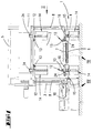
- the device designated as a whole by the number 1 for strapping packages 2 is in portal construction created.
- the device 1 has two parallel vertical columns 3, 4, which at the top by a horizontal yoke 5 are connected.
- With the number 6 is a schematic indicated conveyor line on which the package 2 is moved by the device 1.
- the package 2 itself is on a reusable pallet 7 placed, which in turn rests on the conveyor line 6.
- the vertical columns 3, 4 carry the guides 8 for that Lacing means designed as a plastic flat band 9.
- the latter is known per se and therefore not described in more detail initially U-shaped around the package 2 placed such that the U-web is the top the package 2 is facing.
- the connection in The area between the free leg ends is done by means of a horizontal lance 10 which the strapping means 9 in the area between the feet of the pallet 7 promotes through.
- a connection with the help of a welding lamella also possible.
- To tighten the strap 9 to be able to ensure the package 2 the conveyor line 6 in the strapping plane X-X divided designed.
- the strapping means 9 initially by means of the lance 10 in the direction of the vertical column 4 below the package 2 move. From there it then passes through the guides 8 in a position around the package 2. After tightening of the strapping means 9 around the package then the sealing process can be done.
- the device 1 contains high packages 2 walking beams 11 guided by the vertical columns 3, 4.
- the grippers 12 are needle grippers. This is possible because the edge protection angle 13 usually consist of hard cardboard.
- the edge protection bracket 13 are in the magazines 14 in a horizontal position one above the other; that means the corner edges point up like a ridge.
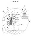
- each gripper 12 includes a carrier 17, whose free longitudinal edge 18 has a rectangular center has a cutout 19 forming a gripper mouth, the base of which is aligned with the longitudinal edge 18. Both sides of the cutout 19 are in the carrier 17th four in a parallel position Needles 20 out.
- each gripper 12 has two approximately at 90 ° to each other Leg 19, from which in a common Level the needles 20 towards each other for gripping drive.
- each gripper 12 sits on a telescopic Arm 24, which in turn rotatably guided horizontally is. While the assigned to the lower package edges Gripper 12 from the arms 15 via the tandem lifting device 16 are worn, are the upper package edges assigned gripper 12 in a suitable manner fixed on the walking beam 11. However, they work with each other similar, so that the description below limited to only one gripper, namely that assigned to the lower left package edge Gripper 12.
- Each carrier 17 is seated on two extendable lifting rods 25 of a sled 26. This in turn is one Axis 27 rotatably assigned to a support slide 28, which support carriage 28 by means of the tandem lifting device 16 in the direction of the associated package edge is relocatable.
- Each magazine 14 is designed as a double magazine. It owns the two in parallel Magazine chambers 29, 30, in each of which a stack of Edge protection angles 13 lying on top of one another in a rider shape. Each magazine stack is by means of one lower edge protection angle attacking drag beam 31 displaceable in the height direction. For this purpose each magazine 14 is assigned a drive 32 which takes the drag beam 31 via a belt drive 33.
- Each magazine 14 is suspended from a gallows 34 the strapping plane X-X shiftable.
- the gallows 34 of the Upper magazines 14 are assigned to the walking beam 11.
- the two lower magazines 14 are against it supported by bottom vertical supports 35, which the latter carry the gallows 34 assigned to them.
- the Moving the lower magazines 14 out of the strapping plane during the strapping process it is not necessary since they are below the package 2 and accordingly do not interfere with the strapping process.
- the movability is only required if the magazine chambers 29, 30 should be loaded.
- the grippers 12 each move so that they are above the relevant one Magazine chamber 29 and 30 lie.
- the upper and lower magazines 14 are used for loading each in directions pointing away from each other Move strapping plane X-X.
- each gripper 12 After a package 2 by means of the conveyor line (6) has moved into the corresponding strapping position, stops conveyor line 6. It is also located each gripper 12 in the downward position, in which is its gripper mouth above an edge protection angle 13 lies. There are now the edge protection angles 13 by means of the respective trailing beam 31 in the upward direction shifted, the upper edge protection angle 13 drives into the gripper mouth. The removal of the Edge protection angle 13 can, however, also by mutual Movement of the gripper 12 and the edge protection angle 13 done. There is now an edge protection bracket 13 in each gripper 12, so the Edge protection angle takeover by merely extending the needle, as illustrated in FIGS. 5 and 12. The needle tips 20 'engage in the material of the Leg of the edge protection bracket 13 a. A possibility of avoiding the edge protection angle 13 not so that the edge protection angle is certain 13 is detected.
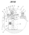
- the next step is that the relevant edge protection angle 13, as shown in FIG. 5 is shown in dash-dot lines, in the downward direction move while the gripper 12 is moving up thereafter, as FIG. 6 emphasizes, to rotate its axis 27, so that the edge protector 13 in question Alignment to the facing edge of the package.
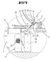
- the tandem lifting device 16 each gripper 12 in the contact position to the package edge brought and there with retracted needles 20 as long held until the strapping process is complete.
- the upper magazines become the strapping process 14 shifted from the strapping plane X-X, so that the Strapping process is not affected.
- the grippers 12 move back to their starting position back while the top magazines 14 drive back into the strapping plane. After further transportation of the package 2, this can then be another Obtain tying as shown in FIG. 3.
Landscapes
- Engineering & Computer Science (AREA)
- Mechanical Engineering (AREA)
- Basic Packing Technique (AREA)
Abstract
Description
Damit die oberen Magazine jedoch nicht mit umreift werden, fahren sie vor dem Umreifen aus der Umreifungsebene. Arbeitstechnisch vorteilhaft ist es, wenn die Greifer in einer zur Umreifungsebene parallelen Ebene liegen und arbeiten. Sie haben daher stets die vorschriftsmäßige Ausrichtung für ein Anlegen der Kantenschutzwinkel. Weitere Vorteile ergeben sich ferner beim Anlegen der Kantenschutzwinkel dadurch, dass die in die Anlagestellung gebrachten Kantenschutzwinkel von den Greifern mit rückgezogenen Nadeln so lange gehalten werden, bis sie durch Umreifen am Packstück festliegen. Schließlich ist noch hervorzuheben, dass die oberen und unteren Magazine jeweils in voneinander weg weisenden Richtungen zum Beladen aus der Umreifungsebene verfahren.
- Fig. 1
- eine Frontansicht der Vorrichtung mit in Beladestellung gebrachtem Packstück vor dem Anlegen der von den Greifern gehaltenen Kantenschutzwinkel,
- Fig. 2
- die Seitenansicht gemäß Pfeilrichtung II in Fig. 1,
- Fig. 3
- in perspektivischer Darstellung das von einer Palette getragene und umschnürte Packstück unter Verwendung der Kantenschutzwinkel,
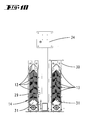
- Fig. 4
- in vergrößertem Maßstab den Ausschnitt nach der Linie IV-IV in Fig. 1, wobei der Greifer auf den obersten Kantenschutzwinkel des Magazins aufsetzt,
- Fig. 5
- die Folgedarstellung der Fig. 4, und zwar bei abgesenkten Kantenschutzwinkeln und aufwärtsgefahrenem Greifer,
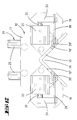
- Fig. 6
- die Folgedarstellung der Fig. 5, jedoch bei in die Ansetzposition geschwenktem Greifer,
- Fig. 7
- die Folgedarstellung der Fig. 6, wobei abweichend gegenüber dieser der Greifer mit dem Kantenschutzwinkel in die Anlagestellung zu der zugekehrten Packstückkante getreten ist,
- Fig. 8
- eine perspektivische Darstellung eines Magazins,
- Fig. 9
- in Einzeldarstellung eine Ansicht des Magazins bei fortgelassenen Abdeckungen,
- Fig. 10
- den Schnitt nach der Linie X-X in Fig. 9,
- Fig. 11
- in perspektivischer Darstellung den Greifer mit Blick in das die Nadeln aufweisende Greifermaul und
- Fig. 12
- einen Längsschnitt durch den Greifer mit in Wirkung zu einem Kantenschutzwinkel gebrachten Nadeln.
Claims (16)
- Vorrichtung (1) zum Unireifen von Packstücken (2), wobei mittels Greifer (12) Kantenschutzwinkel (13) vor dem Umreifen auf die Packstückkanten im Bereich der Umreifungsebene (X-X) gelegt werden, welche Kantenschutzwinkel (13) einem Magazin (14) entnommen werden, dadurch gekennzeichnet, dass der Greifer (12) ein Nadelgreifer ist.
- Vorrichtung (1) nach Anspruch 1 oder insbesondere danach, dadurch gekennzeichnet, dass die Kantenschutzwinkel (13) in den Magazinen (14) in Horizontallage übereinanderliegen.
- Vorrichtung (1) nach einem oder mehreren der vorhergehenden Ansprüche oder insbesondere danach, dadurch gekennzeichnet, dass die Kantenschutzwinkel (13) in der Umreifungsebene (X-X) dem Magazin entnommen werden.
- Vorrichtung (1) nach einem oder mehreren der vorhergehenden Ansprüche oder insbesondere danach, dadurch gekennzeichnet, dass der Greifer (12) zwei etwa im 90°- Winkel zueinander stehende Schenkel (19') ausbildet, aus welchen Schenkeln (19') in einer gemeinsamen Ebene die Nadeln (20) zum Greifen aus jedem Schenkel (19') aufeinander zu fahren.
- Vorrichtung (1) nach einem oder mehreren der vorhergehenden Ansprüche oder insbesondere danach, gekennzeichnet durch mehrere an einem Träger (17) sitzende Nadeln (20), welche längs von einem Hubzylinder (23) verlagerbar sind.
- Vorrichtung (1) nach einem oder mehreren der vorhergehenden Ansprüche oder insbesondere danach, dadurch gekennzeichnet, dass der Greifer (12) an einem teleskopierbaren Arm (24) sitzt, der drehbar horizontal geführt ist.
- Vorrichtung (1) nach einem oder mehreren der vorhergehenden Ansprüche oder insbesondere danach, dadurch gekennzeichnet, dass die Kantenschutzwinkel (13) in dem Magazin (14) reiterförmig übereinanderliegen und mittels eines Schleppbalkens (31) aufwärts verlagerbar sind.
- Vorrichtung (1) nach einem oder mehreren der vorhergehenden Ansprüche oder insbesondere danach, dadurch gekennzeichnet, dass die Kantenschutzwinkel (13) zur Übergabe durch den Greifer (12) in dessen über die Kantenschutzwinkel (13) gebrachtes Greifermaul gehoben werden, so dass die Kantenschutzwinkel-Übernahme durch ledigliches Nadelausfahren erfolgt.
- Vorrichtung (1) nach einem oder mehreren der vorhergehenden Ansprüche oder insbesondere danach, gekennzeichnet durch als ein Doppelmagazin ausgebildetes Magazin (14).
- Vorrichtung (1) nach einem oder mehreren der vorhergehenden Ansprüche oder insbesondere danach, dadurch gekennzeichnet, dass jeder der vier Kantenschutzwinkel-Anlagestellen je ein Greifer (12) mit zugehörigem Magazin zugeordnet ist.
- Vorrichtung (1) nach einem oder mehreren der vorhergehenden Ansprüche oder insbesondere danach, dadurch gekennzeichnet, dass die Magazine (14), an Galgen (34) hängend, horizontal aus der Umreifungsebene (X-X) verlagerbar sind.
- Vorrichtung (1) nach einem oder mehreren der vorhergehenden Ansprüche oder insbesondere danach, dadurch gekennzeichnet, dass die oberen Magazine (14) an einem Hubbalken (11) hängen.
- Vorrichtung (1) nach einem oder mehreren der vorhergehenden Ansprüche oder insbesondere danach, dadurch gekennzeichnet, dass die oberen Magazine (14) zum Umreifen aus der Umreifungsebene gefahren werden.
- Vorrichtung (1) nach einem oder mehreren der vorhergehenden Ansprüche oder insbesondere danach, dadurch gekennzeichnet, dass die Greifer (12) in einer zur Umreifungsebene (X-X) parallelen Ebene (Y-Y) liegen und arbeiten.
- Vorrichtung (1) nach einem oder mehreren der vorhergehenden Ansprüche oder insbesondere danach, dadurch gekennzeichnet, dass die in die Anlagestellung gebrachten Kantenschutzwinkel (13) von den Greifern (12) mit rückgezogenen Nadeln (20) so lange gehalten werden, bis sie durch Umgreifen am Packstück (2) festliegen.
- Vorrichtung (1) nach einem oder mehreren der vorhergehenden Ansprüche oder insbesondere danach, dadurch gekennzeichnet, dass die oberen und unteren Magazine (14) jeweils in voneinander weg weisenden Richtungen zum Beladen aus der Umreifungsebene (X-X) verfahren.
Applications Claiming Priority (2)
| Application Number | Priority Date | Filing Date | Title |
|---|---|---|---|
| DE2000112484 DE10012484A1 (de) | 2000-03-15 | 2000-03-15 | Vorrichtung zum Umreifen von Packstücken |
| DE10012484 | 2000-03-15 |
Publications (2)
| Publication Number | Publication Date |
|---|---|
| EP1136360A2 true EP1136360A2 (de) | 2001-09-26 |
| EP1136360A3 EP1136360A3 (de) | 2002-03-20 |
Family
ID=7634734
Family Applications (1)
| Application Number | Title | Priority Date | Filing Date |
|---|---|---|---|
| EP01105074A Withdrawn EP1136360A3 (de) | 2000-03-15 | 2001-03-02 | Vorrichtung zum Umreifen von Packstücken |
Country Status (2)
| Country | Link |
|---|---|
| EP (1) | EP1136360A3 (de) |
| DE (1) | DE10012484A1 (de) |
Cited By (2)
| Publication number | Priority date | Publication date | Assignee | Title |
|---|---|---|---|---|
| WO2006130404A1 (en) * | 2005-05-31 | 2006-12-07 | Illinois Tool Works Inc. | Apparatus for applying external corner or edge protectors onto external corner or edge regions of packages or palletized loads |
| WO2010029451A1 (de) | 2008-09-11 | 2010-03-18 | Cyklop Gmbh | Umreifungsmaschine für packstücke |
Families Citing this family (3)
| Publication number | Priority date | Publication date | Assignee | Title |
|---|---|---|---|---|
| CN102658877B (zh) * | 2012-05-24 | 2014-07-23 | 浙江中烟工业有限责任公司 | 一种自动加护角的打包机 |
| CN103723299A (zh) * | 2012-10-10 | 2014-04-16 | 鸿富锦精密工业(深圳)有限公司 | 包边装置 |
| DE102019107702B3 (de) * | 2019-03-26 | 2020-05-28 | Signode Industrial Group Llc | Verfahren zur Anordnung eines Kantenschutzmittels an einem Packstück in einer Vorrichtung zum Umreifen von Packstücken sowie Vorrichtung zum Umreifen von Packstücken |
Family Cites Families (1)
| Publication number | Priority date | Publication date | Assignee | Title |
|---|---|---|---|---|
| DE2431153A1 (de) * | 1974-06-28 | 1976-01-15 | Hoffmann Cyklop | Maschine zum umreifen von packstuecken |
-
2000
- 2000-03-15 DE DE2000112484 patent/DE10012484A1/de not_active Withdrawn
-
2001
- 2001-03-02 EP EP01105074A patent/EP1136360A3/de not_active Withdrawn
Cited By (2)
| Publication number | Priority date | Publication date | Assignee | Title |
|---|---|---|---|---|
| WO2006130404A1 (en) * | 2005-05-31 | 2006-12-07 | Illinois Tool Works Inc. | Apparatus for applying external corner or edge protectors onto external corner or edge regions of packages or palletized loads |
| WO2010029451A1 (de) | 2008-09-11 | 2010-03-18 | Cyklop Gmbh | Umreifungsmaschine für packstücke |
Also Published As
| Publication number | Publication date |
|---|---|
| DE10012484A1 (de) | 2001-09-20 |
| EP1136360A3 (de) | 2002-03-20 |
Similar Documents
| Publication | Publication Date | Title |
|---|---|---|
| DE69304965T2 (de) | Vorrichtung zum Anbringen von Eckschützern an palettierten Ladungen | |
| DE3143618C2 (de) | Streckbarer Greiferkopf zur Erfassung und Umbildung einer Gruppe von Gegenständen, wie Flaschen oder dergleichen | |
| EP0077508B1 (de) | Verfahren und Vorrichtung zum Verpacken von palettierten Gutstapeln | |
| DE4203118C2 (de) | Vorrichtung zum Ergreifen und Transportieren von Stapeln flacher Gegenstände | |
| DE2322134A1 (de) | Unabhaengige ueberfuehrungsvorrichtung fuer foerdereinrichtungen | |
| DE7802922U1 (de) | Hubvorrichtung fuer einen hubwagen mit einem vertikal beweglichen mast zum ergreifen und heben von faessern | |
| DE2551252C2 (de) | Rückstapelgerät zum Stapeln von Blattmaterial-Teilstapeln zu einem Gesamtstapel | |
| DE10353351A1 (de) | Roboter und Verfahren zum Umsetzen von Kartonagenstapeln | |
| DE69205364T2 (de) | Einrichtung zum Zuführen von Stapeln von Zuschnitten an eine Verarbeitungsmaschine. | |
| DE2431153A1 (de) | Maschine zum umreifen von packstuecken | |
| CH626023A5 (de) | ||
| EP1136360A2 (de) | Vorrichtung zum Umreifen von Packstücken | |
| DE4425127A1 (de) | Lageranlage zum Kommissionieren | |
| DE4427488A1 (de) | Verfahren zum Palettieren von Stückgutteilen und Stückgutgreifer insbesondere für Roboter, insbesondere zur Paketpalettierung | |
| DE3702708A1 (de) | Vorrichtung zur be- und entpalettierung zylindrischer faesser | |
| DE8811834U1 (de) | Eimergreifer | |
| DE3712939C2 (de) | ||
| DE29916095U1 (de) | Anordnung zum Fördern und Stapeln von überwiegend flachen und flexiblen Gegenständen, insbesondere von Handschuhen | |
| DE1756152A1 (de) | Aufnahmevorrichtung | |
| DE29502308U1 (de) | Vorrichtung zum Transportieren von aus einem Blattpaketstapel entnehmbaren Blattpaketen | |
| DE19504708A1 (de) | Vorrichtung zum Transportieren von aus einem Blattpaketstapel entnehmbaren Blattpaketen | |
| DE2313598A1 (de) | Vorrichtung zum abheben, transportieren und absetzen von plattenartigen werkstuecken zum anbau an stapel- und beschickungsgeraete | |
| DE19513368A1 (de) | Vorrichtung und Verfahren zum Entstapeln bzw. Stapeln von Paletten | |
| AT227168B (de) | Vorrichtung zum Einsetzen von Flaschen od. dgl. in Transportbehälter und zum Entleeren der letzteren | |
| DE2123870B2 (de) | Vorrichtung zum Transportieren von Tafeln oder Platten mit glatter Oberfläche |
Legal Events
| Date | Code | Title | Description |
|---|---|---|---|
| PUAI | Public reference made under article 153(3) epc to a published international application that has entered the european phase |
Free format text: ORIGINAL CODE: 0009012 |
|
| AK | Designated contracting states |
Kind code of ref document: A2 Designated state(s): AT BE CH CY DE DK ES FI FR GB GR IE IT LI LU MC NL PT SE TR |
|
| AX | Request for extension of the european patent |
Free format text: AL;LT;LV;MK;RO;SI |
|
| RIN1 | Information on inventor provided before grant (corrected) |
Inventor name: DER ERFINDER HAT AUF SEINE NENNUNG VERZICHTET. |
|
| PUAL | Search report despatched |
Free format text: ORIGINAL CODE: 0009013 |
|
| AK | Designated contracting states |
Kind code of ref document: A3 Designated state(s): AT BE CH CY DE DK ES FI FR GB GR IE IT LI LU MC NL PT SE TR |
|
| AX | Request for extension of the european patent |
Free format text: AL;LT;LV;MK;RO;SI |
|
| AKX | Designation fees paid | ||
| REG | Reference to a national code |
Ref country code: DE Ref legal event code: 8566 |
|
| STAA | Information on the status of an ep patent application or granted ep patent |
Free format text: STATUS: THE APPLICATION IS DEEMED TO BE WITHDRAWN |
|
| 18D | Application deemed to be withdrawn |
Effective date: 20020921 |