EP1136299A2 - Système d'aération d'un réservoir de carburant - Google Patents
Système d'aération d'un réservoir de carburant Download PDFInfo
- Publication number
- EP1136299A2 EP1136299A2 EP01103801A EP01103801A EP1136299A2 EP 1136299 A2 EP1136299 A2 EP 1136299A2 EP 01103801 A EP01103801 A EP 01103801A EP 01103801 A EP01103801 A EP 01103801A EP 1136299 A2 EP1136299 A2 EP 1136299A2
- Authority
- EP
- European Patent Office
- Prior art keywords
- line
- venting device
- ventilation
- fuel tank
- lines
- Prior art date
- Legal status (The legal status is an assumption and is not a legal conclusion. Google has not performed a legal analysis and makes no representation as to the accuracy of the status listed.)
- Withdrawn
Links
Images

Classifications
-
- B—PERFORMING OPERATIONS; TRANSPORTING
- B60—VEHICLES IN GENERAL
- B60K—ARRANGEMENT OR MOUNTING OF PROPULSION UNITS OR OF TRANSMISSIONS IN VEHICLES; ARRANGEMENT OR MOUNTING OF PLURAL DIVERSE PRIME-MOVERS IN VEHICLES; AUXILIARY DRIVES FOR VEHICLES; INSTRUMENTATION OR DASHBOARDS FOR VEHICLES; ARRANGEMENTS IN CONNECTION WITH COOLING, AIR INTAKE, GAS EXHAUST OR FUEL SUPPLY OF PROPULSION UNITS IN VEHICLES
- B60K15/00—Arrangement in connection with fuel supply of combustion engines or other fuel consuming energy converters, e.g. fuel cells; Mounting or construction of fuel tanks
- B60K15/03—Fuel tanks
- B60K15/035—Fuel tanks characterised by venting means
- B60K15/03504—Fuel tanks characterised by venting means adapted to avoid loss of fuel or fuel vapour, e.g. with vapour recovery systems
- B60K2015/03509—Fuel tanks characterised by venting means adapted to avoid loss of fuel or fuel vapour, e.g. with vapour recovery systems with a droplet separator in the vent line
-
- B—PERFORMING OPERATIONS; TRANSPORTING
- B60—VEHICLES IN GENERAL
- B60K—ARRANGEMENT OR MOUNTING OF PROPULSION UNITS OR OF TRANSMISSIONS IN VEHICLES; ARRANGEMENT OR MOUNTING OF PLURAL DIVERSE PRIME-MOVERS IN VEHICLES; AUXILIARY DRIVES FOR VEHICLES; INSTRUMENTATION OR DASHBOARDS FOR VEHICLES; ARRANGEMENTS IN CONNECTION WITH COOLING, AIR INTAKE, GAS EXHAUST OR FUEL SUPPLY OF PROPULSION UNITS IN VEHICLES
- B60K15/00—Arrangement in connection with fuel supply of combustion engines or other fuel consuming energy converters, e.g. fuel cells; Mounting or construction of fuel tanks
- B60K15/03—Fuel tanks
- B60K15/035—Fuel tanks characterised by venting means
- B60K2015/03523—Arrangements of the venting tube
-
- B—PERFORMING OPERATIONS; TRANSPORTING
- B60—VEHICLES IN GENERAL
- B60K—ARRANGEMENT OR MOUNTING OF PROPULSION UNITS OR OF TRANSMISSIONS IN VEHICLES; ARRANGEMENT OR MOUNTING OF PLURAL DIVERSE PRIME-MOVERS IN VEHICLES; AUXILIARY DRIVES FOR VEHICLES; INSTRUMENTATION OR DASHBOARDS FOR VEHICLES; ARRANGEMENTS IN CONNECTION WITH COOLING, AIR INTAKE, GAS EXHAUST OR FUEL SUPPLY OF PROPULSION UNITS IN VEHICLES
- B60K15/00—Arrangement in connection with fuel supply of combustion engines or other fuel consuming energy converters, e.g. fuel cells; Mounting or construction of fuel tanks
- B60K15/03—Fuel tanks
- B60K15/035—Fuel tanks characterised by venting means
- B60K2015/03561—Venting means working at specific times
- B60K2015/03571—Venting during driving
-
- B—PERFORMING OPERATIONS; TRANSPORTING
- B60—VEHICLES IN GENERAL
- B60K—ARRANGEMENT OR MOUNTING OF PROPULSION UNITS OR OF TRANSMISSIONS IN VEHICLES; ARRANGEMENT OR MOUNTING OF PLURAL DIVERSE PRIME-MOVERS IN VEHICLES; AUXILIARY DRIVES FOR VEHICLES; INSTRUMENTATION OR DASHBOARDS FOR VEHICLES; ARRANGEMENTS IN CONNECTION WITH COOLING, AIR INTAKE, GAS EXHAUST OR FUEL SUPPLY OF PROPULSION UNITS IN VEHICLES
- B60K15/00—Arrangement in connection with fuel supply of combustion engines or other fuel consuming energy converters, e.g. fuel cells; Mounting or construction of fuel tanks
- B60K15/03—Fuel tanks
- B60K15/035—Fuel tanks characterised by venting means
- B60K2015/03561—Venting means working at specific times
- B60K2015/03576—Venting during filling the reservoir
-
- Y—GENERAL TAGGING OF NEW TECHNOLOGICAL DEVELOPMENTS; GENERAL TAGGING OF CROSS-SECTIONAL TECHNOLOGIES SPANNING OVER SEVERAL SECTIONS OF THE IPC; TECHNICAL SUBJECTS COVERED BY FORMER USPC CROSS-REFERENCE ART COLLECTIONS [XRACs] AND DIGESTS
- Y10—TECHNICAL SUBJECTS COVERED BY FORMER USPC
- Y10T—TECHNICAL SUBJECTS COVERED BY FORMER US CLASSIFICATION
- Y10T137/00—Fluid handling
- Y10T137/8593—Systems
- Y10T137/86292—System with plural openings, one a gas vent or access opening
- Y10T137/86324—Tank with gas vent and inlet or outlet
- Y10T137/86332—Vent and inlet or outlet in unitary mounting
Definitions
- the invention relates to a ventilation device for a fuel tank of a motor vehicle with each one led out of the fuel tank Line for a company ventilation and for a refueling ventilation.
- venting devices are in fuel tanks today's motor vehicles are often used and are known from practice.
- the lines each to a near a filler neck of the fuel tank provided expansion tank.
- the expansion tanks also have a common one Activated carbon filters connect with the environment. About the expansion tank and the lines takes place thus a pressure equalization of the fuel tank during the refueling of the motor vehicle and during the Operation of the internal combustion engine of the motor vehicle instead of.
- a disadvantage of the known ventilation device is that the fuel tank with the venting device has a very large surface area. About the very big one For example, by diffusion through the surface A lot of fuel in the wall of the lines Environment. There are also several connecting lines e.g. B. Refueling ventilation, operational ventilation and thus multiple junctions through the fuel vapor can diffuse and thus compliance with Makes emissions legislation impossible.
- the invention is based on the problem of a ventilation device of the type mentioned at the beginning that through them particularly little fuel vapors get around.
- expansion tanks are integrated in the tank and that the lines, at least in one outside the fuel tank located sub-area, a contiguous Have wall.
- the invention when the common outer wall of the two lines designed essentially cylindrical is. As a result, the two lines have a special small common surface.
- the Holder of the inner line according to another advantageous Development of the invention is particularly simple, if the inner line via webs with the outer line connected is.
- the manufacture of the two lines is in accordance with another advantageous development of the invention particularly inexpensive if the inner line is immediate is attached to the outer line.
- the two lines could be the same as in the known ventilation device each led to the activated carbon filter become.
- the venting device according to the invention however requires a particularly low construction effort, if the line of the operating ventilation in the line the refueling vent opens.
- Penetration of fuel from the operating into the Refueling ventilation line can be according to another advantageous development of the invention simple avoid if the mouth of the line of the operating ventilation into the line of the fueling ventilation in one an overflow of fuel at an intended Leaning position of the motor vehicle avoiding height arranged is.
- This line arrangement also has the advantage that fuel that goes through the line's vent is carried away by the line of the fueling ventilation can run back.
- a faulty flow of fuel vapors in the Lines can be advantageous according to another Simply avoid further development of the invention if the Line of the operating ventilation can be closed by a valve is. Another advantage of this design is that when the ventilation is closed a displacement of the during the refueling process Air in the line of the operating ventilation and thus one Overfilling the fuel tank is avoided.
- the Valve can be switched electromagnetically, mechanically or due to the high flow speed in the operating or fueling ventilation.
- the reservoirs in the environment can be according to one other advantageous development of the invention reliably prevent when the reservoir inside of the fuel tank are arranged.
- the connection points the lines on the expansion tanks can also be used within the fuel tank arrange. This leads to a further reduction the escape of fuel vapors.
- the venting device according to the invention is designed be constructively particularly simple when inside of the fuel tank arranged expansion tank are arranged one below the other and if the management of the Operating ventilation through the expansion tank of the refueling ventilation is led.
- This allows the lines enclosing each other directly from the expansion tanks be designed.
- the expansion tank and the This makes cables particularly easy to handle Unity designed.
- the lines can, for example screwed to the expansion tank or to this in Welding process to be attached.
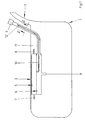
- FIG. 1 shows schematically a fuel tank 1 for a motor vehicle with a filler neck 2 for filling of fuel and with a venting device 3.
- the venting device 3 has an outside of the Fuel tank 1 arranged activated carbon filter 4 and one each attached within the fuel tank Expansion tank 5, 6 for an operating ventilation and for refueling ventilation.
- the expansion tank 5 of the operating ventilation is above the expansion tank 6 of the fueling ventilation connected.
- To the Expansion tanks 5, 6 are each in the fuel tank 1 leading lines 7-8 and out of the fuel tank 1 outgoing lines 10, 11, and Fill level limit an immersion tube is connected. From the fuel tank 1 leading line 11 of the Refueling vent has a larger diameter than the line 10 of the operating ventilation and is up to the Activated carbon filter 4 out.
- the line 11 of the operating ventilation is from the expansion tank 5 of the operating vent through the expansion tank 6 of the fueling ventilation and through a section of the outside of the fuel tank 1 extending line 11 of the fueling ventilation guided.
- a valve 12 is arranged in the immediately before the Activated carbon filter 4 arranged free end of the line 10 of the operating vent.
- the valve 12 can, for example, mechanically during refueling, closed electromagnetically or by an air flow become.
- Figure 2 shows the outside of that shown in Figure 1
- Fuel container 1 arranged lines 10, 11 of the Operating ventilation and refueling ventilation in one Sectional view along the line II - II.
- the line 11 of the fueling ventilation concentrically encloses the line 10 of the operating ventilation.
- a wall 13 of the line 10 of the operating ventilation separates the two lines. This wall 13 thus has no contact with the environment, so that none Fuel vapors directly through this wall 13 in can get around.
- the line 10 of the operating ventilation is by means of webs 14 on line 11 Refueling ventilation maintained.
- Figure 3 shows another embodiment of two together connected lines 15, 16 of the operating ventilation and the fueling vent from Figure 1.
- the cross-sectional line 15 of the factory ventilation immediately attached to line 16 of the refueling vent.
- the two lines 15, 16 have one common portion of a wall 17, which none Has contact with the environment.
- the line 10 as an independent line within the refueling vent only at the outlet of the operating vent to fix.
Landscapes
- Engineering & Computer Science (AREA)
- Life Sciences & Earth Sciences (AREA)
- Sustainable Development (AREA)
- Sustainable Energy (AREA)
- Chemical & Material Sciences (AREA)
- Combustion & Propulsion (AREA)
- Transportation (AREA)
- Mechanical Engineering (AREA)
- Cooling, Air Intake And Gas Exhaust, And Fuel Tank Arrangements In Propulsion Units (AREA)
Applications Claiming Priority (2)
| Application Number | Priority Date | Filing Date | Title |
|---|---|---|---|
| DE10013919 | 2000-03-21 | ||
| DE10013919A DE10013919A1 (de) | 2000-03-21 | 2000-03-21 | Entlüftungseinrichtung für einen Kraftstoffbehälter |
Publications (2)
| Publication Number | Publication Date |
|---|---|
| EP1136299A2 true EP1136299A2 (fr) | 2001-09-26 |
| EP1136299A3 EP1136299A3 (fr) | 2004-11-17 |
Family
ID=7635730
Family Applications (1)
| Application Number | Title | Priority Date | Filing Date |
|---|---|---|---|
| EP01103801A Withdrawn EP1136299A3 (fr) | 2000-03-21 | 2001-02-16 | Système d'aération d'un réservoir de carburant |
Country Status (3)
| Country | Link |
|---|---|
| US (1) | US6491030B2 (fr) |
| EP (1) | EP1136299A3 (fr) |
| DE (1) | DE10013919A1 (fr) |
Cited By (3)
| Publication number | Priority date | Publication date | Assignee | Title |
|---|---|---|---|---|
| EP1780068A2 (fr) * | 2005-10-28 | 2007-05-02 | Kautex Textron GmbH & Co. KG. | Réservoir de combustible |
| EP2923875A1 (fr) * | 2014-03-25 | 2015-09-30 | Magna Steyr Fuel Systems GesmbH | Dispositif de remplissage et procédé de fabrication d'un dispositif de remplissage |
| FR3093475A1 (fr) * | 2019-03-06 | 2020-09-11 | Psa Automobiles Sa | Ensemble d’une tubulure d’admission de fluide et d’un tuyau de degazage pour un reservoir |
Families Citing this family (9)
| Publication number | Priority date | Publication date | Assignee | Title |
|---|---|---|---|---|
| DE10133400C2 (de) * | 2001-07-13 | 2003-08-07 | Siemens Ag | Kraftstoffbehälter |
| DE10355690B4 (de) * | 2003-11-28 | 2011-12-29 | Dr. Ing. H.C. F. Porsche Aktiengesellschaft | Entlüftungseinrichtung für einen Kraftstoffbehälter |
| US7377295B2 (en) * | 2005-04-07 | 2008-05-27 | Traxxas Lp | Fuel filler cap for a model vehicle |
| DE102006037062A1 (de) * | 2006-08-08 | 2008-02-14 | Siemens Ag | Kraftstoffbehälter für ein Kraftfahrzeug |
| DE102006037448A1 (de) * | 2006-08-10 | 2008-02-14 | Bayerische Motoren Werke Ag | Kraftstoffversorgungsanlage eines Kraftfahrzeugs |
| DE102006049344B4 (de) * | 2006-10-19 | 2018-02-08 | Volkswagen Ag | Kraftstoffversorgungsvorrichtung |
| US8887774B2 (en) * | 2008-09-24 | 2014-11-18 | Sartec Corporation | Fuel vapor retention system and methods |
| DE102011118929A1 (de) * | 2011-11-21 | 2013-05-23 | Kautex Textron Gmbh & Co. Kg | Nebenflüssigkeitsbehälter für ein Kfz |
| JP6901452B2 (ja) * | 2018-10-23 | 2021-07-14 | フタバ産業株式会社 | キャニスタ |
Citations (4)
| Publication number | Priority date | Publication date | Assignee | Title |
|---|---|---|---|---|
| US5076242A (en) * | 1990-07-18 | 1991-12-31 | Illinois Tool Works Inc. | Integral fuel line |
| FR2692207A1 (fr) * | 1992-06-11 | 1993-12-17 | Peugeot | Dispositif d'aération d'un réservoir de carburant d'un véhicule automobile. |
| WO1994010491A1 (fr) * | 1992-10-30 | 1994-05-11 | Nobel Plastiques | Canalisation de fluide realisee en matiere plastique |
| FR2728200A1 (fr) * | 1994-12-19 | 1996-06-21 | Peugeot | Dispositif de limitation de remplissage d'un reservoir de carburant et vehicule automobile equipe d'un tel dispositif |
Family Cites Families (11)
| Publication number | Priority date | Publication date | Assignee | Title |
|---|---|---|---|---|
| US3187936A (en) * | 1962-11-01 | 1965-06-08 | Gen Motors Corp | Integral fuel filler pipe and vent tube |
| IT206208Z2 (it) * | 1985-11-15 | 1987-07-13 | Italiana Serrature Torino | Organo di adduzione carburante per veicoli |
| DE3540740A1 (de) * | 1985-11-16 | 1987-05-21 | Porsche Ag | Einfuellstutzen fuer einen kraftstoffbehaelter, insbesondere fuer kraftfahrzeuge |
| DE4023094C2 (de) * | 1989-07-29 | 1996-12-12 | Volkswagen Ag | Kunststoff-Kraftstoffbehälter für ein Kraftfahrzeug |
| US5230360A (en) * | 1990-05-23 | 1993-07-27 | Paul Journee S.A. | Venting system for a fuel tank |
| DE4121323C2 (de) * | 1991-06-27 | 1996-03-14 | Bayerische Motoren Werke Ag | Kraftstoffbehälter für ein Kraftfahrzeug |
| SE469552B (sv) * | 1991-12-18 | 1993-07-26 | Volvo Ab | Avluftningsanordning vid braenslepaafyllningsroer |
| DE19500775C1 (de) * | 1995-01-13 | 1996-07-11 | Daimler Benz Ag | Vorrichtung zum Entlüften und Belüften eines Kraftstofftankes |
| DE19524254C1 (de) * | 1995-07-04 | 1997-01-16 | Mc Micro Compact Car Ag | Kraftstoffbehälter |
| IT1284714B1 (it) * | 1996-07-30 | 1998-05-21 | Ergom Materie Plastiche Spa | Gruppo di bocchettone del serbatoio del carburante di un veicolo. |
| DE19846059A1 (de) * | 1998-10-07 | 2000-04-20 | Benteler Werke Ag | Kraftstoffversorgungsanlage |
-
2000
- 2000-03-21 DE DE10013919A patent/DE10013919A1/de not_active Withdrawn
-
2001
- 2001-02-16 EP EP01103801A patent/EP1136299A3/fr not_active Withdrawn
- 2001-03-21 US US09/813,705 patent/US6491030B2/en not_active Expired - Fee Related
Patent Citations (4)
| Publication number | Priority date | Publication date | Assignee | Title |
|---|---|---|---|---|
| US5076242A (en) * | 1990-07-18 | 1991-12-31 | Illinois Tool Works Inc. | Integral fuel line |
| FR2692207A1 (fr) * | 1992-06-11 | 1993-12-17 | Peugeot | Dispositif d'aération d'un réservoir de carburant d'un véhicule automobile. |
| WO1994010491A1 (fr) * | 1992-10-30 | 1994-05-11 | Nobel Plastiques | Canalisation de fluide realisee en matiere plastique |
| FR2728200A1 (fr) * | 1994-12-19 | 1996-06-21 | Peugeot | Dispositif de limitation de remplissage d'un reservoir de carburant et vehicule automobile equipe d'un tel dispositif |
Cited By (6)
| Publication number | Priority date | Publication date | Assignee | Title |
|---|---|---|---|---|
| EP1780068A2 (fr) * | 2005-10-28 | 2007-05-02 | Kautex Textron GmbH & Co. KG. | Réservoir de combustible |
| EP1780068A3 (fr) * | 2005-10-28 | 2007-08-15 | Kautex Textron GmbH & Co. KG. | Réservoir de combustible |
| CN100486830C (zh) * | 2005-10-28 | 2009-05-13 | 考特克斯·特克斯罗恩有限公司及两合公司 | 燃油箱 |
| EP2923875A1 (fr) * | 2014-03-25 | 2015-09-30 | Magna Steyr Fuel Systems GesmbH | Dispositif de remplissage et procédé de fabrication d'un dispositif de remplissage |
| US9428045B2 (en) | 2014-03-25 | 2016-08-30 | Magna Steyr Fuel Systems Gesmbh | Filling device and method for manufacturing a filling device |
| FR3093475A1 (fr) * | 2019-03-06 | 2020-09-11 | Psa Automobiles Sa | Ensemble d’une tubulure d’admission de fluide et d’un tuyau de degazage pour un reservoir |
Also Published As
| Publication number | Publication date |
|---|---|
| US20020023923A1 (en) | 2002-02-28 |
| US6491030B2 (en) | 2002-12-10 |
| EP1136299A3 (fr) | 2004-11-17 |
| DE10013919A1 (de) | 2001-09-27 |
Similar Documents
| Publication | Publication Date | Title |
|---|---|---|
| DE19932713C2 (de) | Kraftstoffbehälter | |
| DE10120542B4 (de) | Kraftstoffbehälter | |
| EP1216874B1 (fr) | Réservoir de carburant | |
| EP1406781B1 (fr) | Reservoir de carburant | |
| DE3442149A1 (de) | Vorrichtung zur fuellbegrenzung sowie zur be- und entlueftung von behaeltern, insbesondere kraftstoffbehaeltern von kraftfahrzeugen | |
| EP1136299A2 (fr) | Système d'aération d'un réservoir de carburant | |
| DE102006004630A1 (de) | Kraftstoffbehälter | |
| DE2407130A1 (de) | Kraftstoffbehaelter, insbesondere von kraftfahrzeugen | |
| DE19836104A1 (de) | Füllrohr für einen Kraftstofftank | |
| EP1028017A2 (fr) | Réservoir de carburant | |
| DE102010045341B4 (de) | Verfahren zum Füllen eines Kraftstofftanks | |
| EP0403490B1 (fr) | Reservoir de carburant pour vehicules a moteur | |
| EP1199208B1 (fr) | Reservoir de carburant de véhicule avec un embout pour recevoir un pistolet de remplissage de gazole | |
| EP3216640B1 (fr) | Dispositif de soupape | |
| DE3602101C2 (de) | Einfüllstutzen für einen Reservekanister für bleifreies Benzin | |
| DE4102961A1 (de) | Tankanordnung fuer ein kraftfahrzeug | |
| DE3803670C1 (fr) | ||
| DE60007687T2 (de) | Vorrichtung zur Rückgewinnung und Kontrolle von Kraftstoffdämpfen in einem Fahrzeugtank | |
| EP3738810A1 (fr) | Dispositif d'aération d'un réservoir de véhicule automobile | |
| EP3738811B1 (fr) | Dispositif d'aération d'un réservoir de véhicule automobile | |
| EP0502326A1 (fr) | Barrière d'écoulement pour système d'aération d'un réservoir de carburant | |
| DE102006056707B4 (de) | Reduktionsmittelbehälter und Reduktionsmittelanordnung zum Einfüllen und/oder Nachfüllen von Reduktionsmittel | |
| EP0763441B1 (fr) | Dispositif d'aération du réservoir de carburant d'un véhicule à moteur | |
| DE102007035421A1 (de) | Tankeinrichtung | |
| DE10324779A1 (de) | Einrichtung zur Versorgung einer Brennkraftmaschine mit Kraftstoff |
Legal Events
| Date | Code | Title | Description |
|---|---|---|---|
| PUAI | Public reference made under article 153(3) epc to a published international application that has entered the european phase |
Free format text: ORIGINAL CODE: 0009012 |
|
| AK | Designated contracting states |
Kind code of ref document: A2 Designated state(s): AT BE CH CY DE DK ES FI FR GB GR IE IT LI LU MC NL PT SE TR |
|
| AX | Request for extension of the european patent |
Free format text: AL;LT;LV;MK;RO;SI |
|
| RAP1 | Party data changed (applicant data changed or rights of an application transferred) |
Owner name: SIEMENS AKTIENGESELLSCHAFT |
|
| PUAL | Search report despatched |
Free format text: ORIGINAL CODE: 0009013 |
|
| AK | Designated contracting states |
Kind code of ref document: A3 Designated state(s): AT BE CH CY DE DK ES FI FR GB GR IE IT LI LU MC NL PT SE TR |
|
| AX | Request for extension of the european patent |
Extension state: AL LT LV MK RO SI |
|
| RIC1 | Information provided on ipc code assigned before grant |
Ipc: 7F 16L 11/22 B Ipc: 7B 60K 15/01 B Ipc: 7B 60K 15/035 A |
|
| STAA | Information on the status of an ep patent application or granted ep patent |
Free format text: STATUS: THE APPLICATION IS DEEMED TO BE WITHDRAWN |
|
| 18D | Application deemed to be withdrawn |
Effective date: 20040901 |