EP1136174A1 - Dispositif de traitement de surfaces - Google Patents
Dispositif de traitement de surfaces Download PDFInfo
- Publication number
- EP1136174A1 EP1136174A1 EP01106039A EP01106039A EP1136174A1 EP 1136174 A1 EP1136174 A1 EP 1136174A1 EP 01106039 A EP01106039 A EP 01106039A EP 01106039 A EP01106039 A EP 01106039A EP 1136174 A1 EP1136174 A1 EP 1136174A1
- Authority
- EP
- European Patent Office
- Prior art keywords
- set according
- equipment set
- separator
- removing device
- vacuum system
- Prior art date
- Legal status (The legal status is an assumption and is not a legal conclusion. Google has not performed a legal analysis and makes no representation as to the accuracy of the status listed.)
- Granted
Links
Images

Classifications
-
- A—HUMAN NECESSITIES
- A47—FURNITURE; DOMESTIC ARTICLES OR APPLIANCES; COFFEE MILLS; SPICE MILLS; SUCTION CLEANERS IN GENERAL
- A47L—DOMESTIC WASHING OR CLEANING; SUCTION CLEANERS IN GENERAL
- A47L9/00—Details or accessories of suction cleaners, e.g. mechanical means for controlling the suction or for effecting pulsating action; Storing devices specially adapted to suction cleaners or parts thereof; Carrying-vehicles specially adapted for suction cleaners
- A47L9/10—Filters; Dust separators; Dust removal; Automatic exchange of filters
- A47L9/14—Bags or the like; Rigid filtering receptacles; Attachment of, or closures for, bags or receptacles
- A47L9/1409—Rigid filtering receptacles
-
- A—HUMAN NECESSITIES
- A47—FURNITURE; DOMESTIC ARTICLES OR APPLIANCES; COFFEE MILLS; SPICE MILLS; SUCTION CLEANERS IN GENERAL
- A47L—DOMESTIC WASHING OR CLEANING; SUCTION CLEANERS IN GENERAL
- A47L9/00—Details or accessories of suction cleaners, e.g. mechanical means for controlling the suction or for effecting pulsating action; Storing devices specially adapted to suction cleaners or parts thereof; Carrying-vehicles specially adapted for suction cleaners
- A47L9/10—Filters; Dust separators; Dust removal; Automatic exchange of filters
- A47L9/14—Bags or the like; Rigid filtering receptacles; Attachment of, or closures for, bags or receptacles
- A47L9/149—Emptying means; Reusable bags
-
- A—HUMAN NECESSITIES
- A47—FURNITURE; DOMESTIC ARTICLES OR APPLIANCES; COFFEE MILLS; SPICE MILLS; SUCTION CLEANERS IN GENERAL
- A47L—DOMESTIC WASHING OR CLEANING; SUCTION CLEANERS IN GENERAL
- A47L9/00—Details or accessories of suction cleaners, e.g. mechanical means for controlling the suction or for effecting pulsating action; Storing devices specially adapted to suction cleaners or parts thereof; Carrying-vehicles specially adapted for suction cleaners
- A47L9/10—Filters; Dust separators; Dust removal; Automatic exchange of filters
- A47L9/19—Means for monitoring filtering operation
-
- A—HUMAN NECESSITIES
- A47—FURNITURE; DOMESTIC ARTICLES OR APPLIANCES; COFFEE MILLS; SPICE MILLS; SUCTION CLEANERS IN GENERAL
- A47L—DOMESTIC WASHING OR CLEANING; SUCTION CLEANERS IN GENERAL
- A47L9/00—Details or accessories of suction cleaners, e.g. mechanical means for controlling the suction or for effecting pulsating action; Storing devices specially adapted to suction cleaners or parts thereof; Carrying-vehicles specially adapted for suction cleaners
- A47L9/28—Installation of the electric equipment, e.g. adaptation or attachment to the suction cleaner; Controlling suction cleaners by electric means
- A47L9/2805—Parameters or conditions being sensed
- A47L9/2821—Pressure, vacuum level or airflow
-
- A—HUMAN NECESSITIES
- A47—FURNITURE; DOMESTIC ARTICLES OR APPLIANCES; COFFEE MILLS; SPICE MILLS; SUCTION CLEANERS IN GENERAL
- A47L—DOMESTIC WASHING OR CLEANING; SUCTION CLEANERS IN GENERAL
- A47L9/00—Details or accessories of suction cleaners, e.g. mechanical means for controlling the suction or for effecting pulsating action; Storing devices specially adapted to suction cleaners or parts thereof; Carrying-vehicles specially adapted for suction cleaners
- A47L9/28—Installation of the electric equipment, e.g. adaptation or attachment to the suction cleaner; Controlling suction cleaners by electric means
- A47L9/2836—Installation of the electric equipment, e.g. adaptation or attachment to the suction cleaner; Controlling suction cleaners by electric means characterised by the parts which are controlled
- A47L9/2842—Suction motors or blowers
-
- A—HUMAN NECESSITIES
- A47—FURNITURE; DOMESTIC ARTICLES OR APPLIANCES; COFFEE MILLS; SPICE MILLS; SUCTION CLEANERS IN GENERAL
- A47L—DOMESTIC WASHING OR CLEANING; SUCTION CLEANERS IN GENERAL
- A47L9/00—Details or accessories of suction cleaners, e.g. mechanical means for controlling the suction or for effecting pulsating action; Storing devices specially adapted to suction cleaners or parts thereof; Carrying-vehicles specially adapted for suction cleaners
- A47L9/28—Installation of the electric equipment, e.g. adaptation or attachment to the suction cleaner; Controlling suction cleaners by electric means
- A47L9/2889—Safety or protection devices or systems, e.g. for prevention of motor over-heating or for protection of the user
-
- B—PERFORMING OPERATIONS; TRANSPORTING
- B08—CLEANING
- B08B—CLEANING IN GENERAL; PREVENTION OF FOULING IN GENERAL
- B08B15/00—Preventing escape of dirt or fumes from the area where they are produced; Collecting or removing dirt or fumes from that area
- B08B15/04—Preventing escape of dirt or fumes from the area where they are produced; Collecting or removing dirt or fumes from that area from a small area, e.g. a tool
-
- B—PERFORMING OPERATIONS; TRANSPORTING
- B23—MACHINE TOOLS; METAL-WORKING NOT OTHERWISE PROVIDED FOR
- B23Q—DETAILS, COMPONENTS, OR ACCESSORIES FOR MACHINE TOOLS, e.g. ARRANGEMENTS FOR COPYING OR CONTROLLING; MACHINE TOOLS IN GENERAL CHARACTERISED BY THE CONSTRUCTION OF PARTICULAR DETAILS OR COMPONENTS; COMBINATIONS OR ASSOCIATIONS OF METAL-WORKING MACHINES, NOT DIRECTED TO A PARTICULAR RESULT
- B23Q11/00—Accessories fitted to machine tools for keeping tools or parts of the machine in good working condition or for cooling work; Safety devices specially combined with or arranged in, or specially adapted for use in connection with, machine tools
- B23Q11/0042—Devices for removing chips
- B23Q11/0046—Devices for removing chips by sucking
-
- B—PERFORMING OPERATIONS; TRANSPORTING
- B24—GRINDING; POLISHING
- B24B—MACHINES, DEVICES, OR PROCESSES FOR GRINDING OR POLISHING; DRESSING OR CONDITIONING OF ABRADING SURFACES; FEEDING OF GRINDING, POLISHING, OR LAPPING AGENTS
- B24B55/00—Safety devices for grinding or polishing machines; Accessories fitted to grinding or polishing machines for keeping tools or parts of the machine in good working condition
- B24B55/06—Dust extraction equipment on grinding or polishing machines
Definitions
- the invention relates to a device set for processing of surfaces, especially on a set of equipment Processing contaminated floor areas in the Construction industry.
- devices for the removal of material from surfaces known variously.
- devices and Devices for removing layers of floor coverings in widely used in the construction industry.
- a method and a device for displaying the degree of filling of the dust filter bag in a vacuum cleaner is known.
- This is in detail a filter change indicator with a comparator for the differential pressure comparison, the comparator being connected to a downstream dust filter bag filling level indicator.
- Such a display is suitable for indicating when the pores of the dust filter bag become increasingly clogged in suction operation due to the fine dust absorbed. If airy materials are sucked in, there is less pressure drop inside the dust filter bag. This makes it possible, on the one hand, to achieve better dust filter utilization when picking up fine dust without filter clogging, and on the other hand to avoid overfilling the filter bag when vacuuming airy material.
- the problem of using a filter bag cannot be transferred to the concrete milling machine described at the beginning.
- the method is usually a manually movable one Tiller used. Independent and in addition to that Tillers as working tools are material and Staff locks provided. Based on this state of the technical equipment and the known method for Processing contaminated floor areas will be the above mentioned extensive maintenance of negative pressure, to be guaranteed Foreclosure measures and the need for additional Equipment for full personal protection perceived as disadvantageous.
- the object of the invention is a set of equipment for processing of surfaces, in particular a set of equipment for processing of contaminated floor space to provide the without complicated and time-consuming technical measures required security guaranteed.
- the invention is based on a Embodiment explained in more detail.
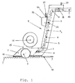
- the equipment set comprises a material-removing device, as shown in Fig. 1 is designed as a tiller 1.
- the Tiller has a relatively flat bottom section 2, the one Housing to accommodate a wide, not shown in detail Rolling mill 3 forms.
- the suction line consists of a plastic tube 6, on the two ends of two metal knee connectors 7 are attached and extends inside a pillar portion 9 the tiller.
- the suction line 5 is at one end with the Intake manifold 4 and at the other end with one Hose connector 11 connected to the one Suction hose 13 with an inner diameter of 50 mm and one Length up to 100 m is appropriate.
- the milling cutter 3 accommodated in the bottom section 2 is over a V-belt 15 with one on the bottom section 2 supported drive motor 17 connected.
- On the down directed surface of the bottom portion 2 is a circumferential lip seal 18 attached in the attached State of the tiller on the floor surface 19 the interior of the housing with the milling cutter 3 accommodated therein seals airtight on the outside.
- the drive motor can with one in the upper section of the tiller Hand switch 20 can be switched on and off.
- a sensor 21 is installed, which according to externally connected to a differential pressure switch 23.
- a differential pressure switch 23 At the Differential pressure switch 23 are a current-differential pressure connection 24 and a 230/380 volt connection 25.
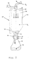
- the suction hose 13 consists of a steel-reinforced plastic and leads to the in Fig. 2 shown pre-separator 27, which is usually in a different room than the tiller shown in Fig. 1 located.
- the pre-separator 27 consists essentially of one Container 28, which at its upper end with a lid 29th is provided.
- the cover 29 has a connecting piece 26 which the suction hose 13 leading to the tiller 1 is attached is.
- a disposal pipe 33 provided with a Sword slide 35 and a bag clamp 37 is equipped.
- the bag clamp is used to attach a disposal container 39 in the form of a flexible sack in which the milled material 41 can be included.
- the inside of the container 27 is with the outside air connected by a false air damper 43.
- On the Side wall of the container 27 is also a sight glass 45 built in, which functions as a level indicator Fulfills.
- the container 28 of the pre-separator 27 is finally by another suction hose 31 with an inner diameter of 70 mm and a length of up to 50 m with that in FIG. 3 shown vacuum unit 47 connected.
- a commercially available vacuum unit 47 is used Vacuum unit with a minimum output of 9.5 KW and with a filter system for the separation of carcinogenic dusts.
- the Filter system consists of a pre-filter, a coarse filter and a fine filter.
- the vacuum unit 47 is switched on, so that the vacuum required to suck off the material removed in the tiller 1 is generated.
- a pressure P 1 is produced in the suction line 5 and thus also in the housing of the bottom section 1.
- a lower pressure (stronger negative pressure) P 2 is produced in the container 28 of the pre-separator 27, which in turn is higher than the pressure P 3 in the suction hose 31 which leads to the negative pressure unit 45.
- P 1 > P 2 > P 3rd Fulfills Due to the all-round, highly abrasion-resistant, 5 mm thick lip seal 19 made of plastic, the pressure losses at the tiller 1 are considerably reduced.
- the motor 17 is switched on and the milling cutter 3 is driven by means of the V-belt 15.
- the surface material such as a pollutant-containing building material, in which asbestos, PCB, or PAH are included as additives to increase the abrasion resistance, is peeled off the floor by means of the diamond-coated milling lamellae and suctioned off in the direction of rotation of the lamellae towards the operator under the influence of the negative pressure P 1 .
- the combination of the knee connections 9 made of steel with the suction line 5 made of plastic ensures that the milled material is forwarded to the pre-separator through the suction line 13 with reduced wear and reduced vibrations.
- the differential pressure measuring device 23 Through the sensor 21 of the differential pressure measuring device 23 it is possible to detect an undesirable increase in pressure and the immediate automatic shutdown of the tiller 1 bring about without operating the hand switch 20 to have to.
- the milled material 41 then passes through the suction hose 13 into the pre-separator 27 shown in FIG. 2 and settles in the bottom section of the container 28.
- the milled material 41 can be metered into the sack 39 located underneath and fastened to the end section of the container 27 by means of the sack clamp 37.
- the filled sack 39 below the pre-separator 27 is removed while the vacuum unit 47 is running, which prevents the milled material from trickling down or contaminated fine dust from escaping from the container 28.
- the level of the milled material 41 can be monitored by the level indicator 45, which is designed here as a sight glass.
- the faulty air damper 43 can be be operated to automatically turn off the tiller 1 if it is determined that a Irregularity in the function of the pre-separator, such as Example, an overfill of the container 28 has occurred.
- the pre-separator is 27 on a mobile stand, not shown in detail Installed.
- Equipment set foreclosure measures the elaborate Keeping rooms under pressure and the use of locks and a water management system.
- the invention is based on the implementation of the above Device system not limited.
- the Tiller for machining edge areas one to one renovating room with an additional router be equipped, also on the suction line 5 connected.
- Another embodiment of the invention Device system is not just at the material-removing device, i.e. on the tiller 1, but also on the pre-separator 27 shown in FIG. 2
- Differential pressure switch with a corresponding, inside the Provide container 27 attached sensor.
- a device set for processing surfaces has one material-removing device (1) and a device thereon connected, together with this a closed one Vacuum unit forming vacuum system (47) for suction of worn surface material.
- the material-removing Device (1) has a differential pressure switch (23) for automatic shutdown of the device when falling below a certain pressure difference between the vacuum system and outside air.
Applications Claiming Priority (2)
| Application Number | Priority Date | Filing Date | Title |
|---|---|---|---|
| DE10012182 | 2000-03-13 | ||
| DE10012182A DE10012182C1 (de) | 2000-03-13 | 2000-03-13 | Gerätesatz zur Bearbeitung von Oberflächen |
Publications (2)
| Publication Number | Publication Date |
|---|---|
| EP1136174A1 true EP1136174A1 (fr) | 2001-09-26 |
| EP1136174B1 EP1136174B1 (fr) | 2005-08-17 |
Family
ID=7634544
Family Applications (1)
| Application Number | Title | Priority Date | Filing Date |
|---|---|---|---|
| EP01106039A Expired - Lifetime EP1136174B1 (fr) | 2000-03-13 | 2001-03-12 | Dispositif de traitement de surfaces |
Country Status (4)
| Country | Link |
|---|---|
| EP (1) | EP1136174B1 (fr) |
| AT (1) | ATE302091T1 (fr) |
| DE (2) | DE10012182C1 (fr) |
| ES (1) | ES2248180T3 (fr) |
Cited By (3)
| Publication number | Priority date | Publication date | Assignee | Title |
|---|---|---|---|---|
| EP2946710A3 (fr) * | 2014-05-20 | 2016-02-24 | Festool GmbH | Machine-outil manuelle dotée d'un raccord d'évacuation de particules |
| EP3678786A4 (fr) * | 2017-09-05 | 2021-06-02 | Husqvarna AB | Séparateur et procédé de fonctionnement d'un séparateur |
| WO2021165521A1 (fr) | 2020-02-21 | 2021-08-26 | Fraunhofer-Gesellschaft zur Förderung der angewandten Forschung eingetragener Verein | Dispositif et procédé pour enlever de la matière à partir de matériaux composites à fibres, en particulier pour un biseautage |
Families Citing this family (5)
| Publication number | Priority date | Publication date | Assignee | Title |
|---|---|---|---|---|
| DE102007059930B3 (de) * | 2007-12-04 | 2009-02-19 | Kurz, Gerhard | Vorrichtung zur Steuerung oder Regelung der Motorleistung eines Staubsaugers |
| NL2012364B1 (en) * | 2014-03-05 | 2015-12-03 | Blastrac B V | Grinding machine and method for grinding a floor surface. |
| DE102014014373B4 (de) * | 2014-10-02 | 2016-05-04 | deconta GmbH | Verfahren zur Absaugung von Schleifstaub und Saugvorrichtung |
| CN106141795A (zh) * | 2016-08-03 | 2016-11-23 | 长葛市世军机械加工厂 | 用于机械加工的机床卷屑装置 |
| FR3067273A1 (fr) * | 2017-06-07 | 2018-12-14 | M.B.H. Developpement | Dispositif de surfacage a utilisation securisee |
Citations (12)
| Publication number | Priority date | Publication date | Assignee | Title |
|---|---|---|---|---|
| GB100817A (en) * | 1916-01-06 | 1916-07-13 | Donald Fraser | Apparatus for Removing Dust and the like in the Operation of Stone-cutting and other Tools. |
| DE1777147A1 (de) * | 1967-09-14 | 1971-04-01 | Phillips Drill Co | Schlaghammer |
| US3608968A (en) * | 1969-04-03 | 1971-09-28 | Christensen Diamond Prod Co | Pavement cutting and water and cutting pickup apparatus |
| GB1259898A (en) * | 1969-05-12 | 1972-01-12 | Tac Construction Materials Ltd | Improvements in apparatus for stripping insulating coatings |
| EP0022435A1 (fr) * | 1979-07-06 | 1981-01-14 | Fläkt Aktiebolag | Système d'évacuation pour déchets en poussière |
| DE3000390A1 (de) * | 1980-01-08 | 1981-07-09 | Günter 7155 Oppenweiler Lind | Schneidmaschine, insbesondere zum einschneiden von nuten und/oder fugen in industriefussboeden |
| DE3219391A1 (de) * | 1982-05-24 | 1983-11-24 | Guido Oberdorfer Wap-Maschinen, 7919 Bellenberg | Schmutzsauger |
| JPS62277253A (ja) * | 1986-05-23 | 1987-12-02 | Sato Kogyo Co Ltd | 汚染コンクリ−ト表面研削機 |
| US4923251A (en) * | 1988-04-04 | 1990-05-08 | Sato Kogyo Co., Ltd. | Apparatus for removing asbestos and like materials from a surface |
| EP0377100A1 (fr) * | 1988-12-30 | 1990-07-11 | C. & E. FEIN GmbH & Co. | Dépoussiéreur et instrument de travail exempt de poussière |
| DE4238564A1 (de) * | 1992-11-14 | 1994-05-19 | Fein C & E | Elektrowerkzeug mit Absaugung |
| DE19822223A1 (de) * | 1998-05-18 | 1999-12-02 | Kaefer Isoliertechnik | Betonfräse zum Fräsen von, insbesondere beschichteten, Beton- oder Estrichböden |
Family Cites Families (1)
| Publication number | Priority date | Publication date | Assignee | Title |
|---|---|---|---|---|
| DE4323222C2 (de) * | 1993-07-12 | 2002-05-02 | Miele & Cie | Verfahren und Einrichtung zur Füllgradanzeige des Staubfilterbeutels in einem Staubsauger |
-
2000
- 2000-03-13 DE DE10012182A patent/DE10012182C1/de not_active Expired - Fee Related
-
2001
- 2001-03-12 DE DE50107088T patent/DE50107088D1/de not_active Expired - Lifetime
- 2001-03-12 ES ES01106039T patent/ES2248180T3/es not_active Expired - Lifetime
- 2001-03-12 AT AT01106039T patent/ATE302091T1/de active
- 2001-03-12 EP EP01106039A patent/EP1136174B1/fr not_active Expired - Lifetime
Patent Citations (12)
| Publication number | Priority date | Publication date | Assignee | Title |
|---|---|---|---|---|
| GB100817A (en) * | 1916-01-06 | 1916-07-13 | Donald Fraser | Apparatus for Removing Dust and the like in the Operation of Stone-cutting and other Tools. |
| DE1777147A1 (de) * | 1967-09-14 | 1971-04-01 | Phillips Drill Co | Schlaghammer |
| US3608968A (en) * | 1969-04-03 | 1971-09-28 | Christensen Diamond Prod Co | Pavement cutting and water and cutting pickup apparatus |
| GB1259898A (en) * | 1969-05-12 | 1972-01-12 | Tac Construction Materials Ltd | Improvements in apparatus for stripping insulating coatings |
| EP0022435A1 (fr) * | 1979-07-06 | 1981-01-14 | Fläkt Aktiebolag | Système d'évacuation pour déchets en poussière |
| DE3000390A1 (de) * | 1980-01-08 | 1981-07-09 | Günter 7155 Oppenweiler Lind | Schneidmaschine, insbesondere zum einschneiden von nuten und/oder fugen in industriefussboeden |
| DE3219391A1 (de) * | 1982-05-24 | 1983-11-24 | Guido Oberdorfer Wap-Maschinen, 7919 Bellenberg | Schmutzsauger |
| JPS62277253A (ja) * | 1986-05-23 | 1987-12-02 | Sato Kogyo Co Ltd | 汚染コンクリ−ト表面研削機 |
| US4923251A (en) * | 1988-04-04 | 1990-05-08 | Sato Kogyo Co., Ltd. | Apparatus for removing asbestos and like materials from a surface |
| EP0377100A1 (fr) * | 1988-12-30 | 1990-07-11 | C. & E. FEIN GmbH & Co. | Dépoussiéreur et instrument de travail exempt de poussière |
| DE4238564A1 (de) * | 1992-11-14 | 1994-05-19 | Fein C & E | Elektrowerkzeug mit Absaugung |
| DE19822223A1 (de) * | 1998-05-18 | 1999-12-02 | Kaefer Isoliertechnik | Betonfräse zum Fräsen von, insbesondere beschichteten, Beton- oder Estrichböden |
Non-Patent Citations (1)
| Title |
|---|
| PATENT ABSTRACTS OF JAPAN vol. 012, no. 160 (M - 697) 14 May 1988 (1988-05-14) * |
Cited By (6)
| Publication number | Priority date | Publication date | Assignee | Title |
|---|---|---|---|---|
| EP2946710A3 (fr) * | 2014-05-20 | 2016-02-24 | Festool GmbH | Machine-outil manuelle dotée d'un raccord d'évacuation de particules |
| EP3678786A4 (fr) * | 2017-09-05 | 2021-06-02 | Husqvarna AB | Séparateur et procédé de fonctionnement d'un séparateur |
| US11185808B2 (en) | 2017-09-05 | 2021-11-30 | Husqvarna Ab | Separator and method of operating a separator |
| AU2018330396B2 (en) * | 2017-09-05 | 2023-08-17 | Husqvarna Ab | Separator and method of operating a separator |
| WO2021165521A1 (fr) | 2020-02-21 | 2021-08-26 | Fraunhofer-Gesellschaft zur Förderung der angewandten Forschung eingetragener Verein | Dispositif et procédé pour enlever de la matière à partir de matériaux composites à fibres, en particulier pour un biseautage |
| DE102020104689A1 (de) | 2020-02-21 | 2021-08-26 | Fraunhofer-Gesellschaft zur Förderung der angewandten Forschung eingetragener Verein | Vorrichtung und Verfahren für einen Materialabtrag an Faserverbundwerkstoffen, insbesondere zum Schäften |
Also Published As
| Publication number | Publication date |
|---|---|
| ES2248180T3 (es) | 2006-03-16 |
| ATE302091T1 (de) | 2005-09-15 |
| EP1136174B1 (fr) | 2005-08-17 |
| DE10012182C1 (de) | 2001-08-09 |
| DE50107088D1 (de) | 2005-09-22 |
Similar Documents
| Publication | Publication Date | Title |
|---|---|---|
| DE102004007716B3 (de) | Fräsmaschine sowie Verfahren zum Bearbeiten von Bodenoberflächen | |
| DE102008027050A1 (de) | Verfahren und Vorrichtung zum automatischen Kanten - Schleifen von Glasplatten unter Reinraumbedingungen | |
| DE10012182C1 (de) | Gerätesatz zur Bearbeitung von Oberflächen | |
| EP3152767B1 (fr) | Appareil et procédé pour déblayer de matériaux contaminés | |
| EP3881923B1 (fr) | Séparateur d'aérosol, ainsi que procédé d'installation d'un élément de filtre à coalescence dans un séparateur d'aérosol | |
| EP0413129A2 (fr) | Procédé et dispositif pour transporter des fluides contenant des résidus de production | |
| DE202015009698U1 (de) | Filteranlage zur Filtrierung von, insbesondere kontaminierten, Luftstäuben | |
| DE102004008101A1 (de) | Immissionsschutzvorrichtung | |
| EP3002081A2 (fr) | Procede d'aspiration de poussiere d'abrasion et dispositif d'aspiration | |
| DE102010047529A1 (de) | Trennschleifgerät mit Staubabsaugung | |
| DE3337549C2 (fr) | ||
| DE102014013129B4 (de) | Werkzeugmaschine zur spanabhebenden Bearbeitung eines Werkstücks mittels einer Minimalmengenschmierung sowie Verfahren zur Reinigung einer derartigen Werkzeugmaschine | |
| DE102020133149B4 (de) | Entstaubungsvorrichtung mit einer Steuerung für wenigstens zwei Betriebsmodi und Verfahren zur Steuerung einer Entstaubungsvorrichtung | |
| DE10047443C2 (de) | Verfahren und Vorrichtung zum Beseitigen von Bodenbelägen | |
| DE202019101323U1 (de) | Vorrichtung zur Demontage schadstoffbelasteter Baustoffschichten | |
| EP4103348A1 (fr) | Dispositif et système de recouvrement d'un espace de coupe pouvant être produit par une machine-outil, et procédé d'aspiration de poussière hors d'une zone de travail d'une machine-outil | |
| DE102017011508A1 (de) | Entsorgungseinrichtung für staubbelastete Luft | |
| EP1039068A1 (fr) | Dispositif et méthode de démolition de parties de construction | |
| DE102017113210B3 (de) | Vorrichtung zur Sanierung von gesundheitsschädliche Stoffe aufweisenden Fußböden | |
| EP1361941B1 (fr) | Procede d'enlevement d'une couche externe de ma onnerie, et dispositif d'enlevement de la couche externe, notamment de mortier de jointoiement | |
| DE102006009965B4 (de) | Absaug-Anlage für eine spanabhebende Bearbeitungs-Maschine | |
| EP4015723A1 (fr) | Dispositif séparateur atmosphérique et procédé | |
| DE19523549A1 (de) | Verfahren und Einrichtung zum Dekontaminieren der Innenwandungen von Rohren und Behältern durch Abtragung der Kontaminationsschicht | |
| DE4108782C1 (en) | Contamination-free exchange of asbestos contg. fire protection flaps - includes sepg. ventilation segments, applying sealant around air channel installing stack and sepn. unit, placing flap in sack, vacuuming partitioned areas, etc. | |
| DE202004002444U1 (de) | Fräsmaschine zum Bearbeiten von Bodenoberflächen |
Legal Events
| Date | Code | Title | Description |
|---|---|---|---|
| PUAI | Public reference made under article 153(3) epc to a published international application that has entered the european phase |
Free format text: ORIGINAL CODE: 0009012 |
|
| AK | Designated contracting states |
Kind code of ref document: A1 Designated state(s): AT BE CH CY DE DK ES FI FR GB GR IE IT LI LU MC NL PT SE TR |
|
| AX | Request for extension of the european patent |
Free format text: AL;LT;LV;MK;RO;SI |
|
| 17P | Request for examination filed |
Effective date: 20020326 |
|
| AKX | Designation fees paid |
Free format text: AT BE CH CY DE DK ES FI FR GB GR IE IT LI LU MC NL PT SE TR |
|
| 17Q | First examination report despatched |
Effective date: 20040202 |
|
| GRAP | Despatch of communication of intention to grant a patent |
Free format text: ORIGINAL CODE: EPIDOSNIGR1 |
|
| GRAS | Grant fee paid |
Free format text: ORIGINAL CODE: EPIDOSNIGR3 |
|
| GRAA | (expected) grant |
Free format text: ORIGINAL CODE: 0009210 |
|
| AK | Designated contracting states |
Kind code of ref document: B1 Designated state(s): AT BE CH CY DE DK ES FI FR GB GR IE IT LI LU MC NL PT SE TR |
|
| PG25 | Lapsed in a contracting state [announced via postgrant information from national office to epo] |
Ref country code: IE Free format text: LAPSE BECAUSE OF FAILURE TO SUBMIT A TRANSLATION OF THE DESCRIPTION OR TO PAY THE FEE WITHIN THE PRESCRIBED TIME-LIMIT Effective date: 20050817 Ref country code: NL Free format text: LAPSE BECAUSE OF FAILURE TO SUBMIT A TRANSLATION OF THE DESCRIPTION OR TO PAY THE FEE WITHIN THE PRESCRIBED TIME-LIMIT Effective date: 20050817 Ref country code: GB Free format text: LAPSE BECAUSE OF FAILURE TO SUBMIT A TRANSLATION OF THE DESCRIPTION OR TO PAY THE FEE WITHIN THE PRESCRIBED TIME-LIMIT Effective date: 20050817 Ref country code: TR Free format text: LAPSE BECAUSE OF FAILURE TO SUBMIT A TRANSLATION OF THE DESCRIPTION OR TO PAY THE FEE WITHIN THE PRESCRIBED TIME-LIMIT Effective date: 20050817 Ref country code: FI Free format text: LAPSE BECAUSE OF FAILURE TO SUBMIT A TRANSLATION OF THE DESCRIPTION OR TO PAY THE FEE WITHIN THE PRESCRIBED TIME-LIMIT Effective date: 20050817 |
|
| REG | Reference to a national code |
Ref country code: GB Ref legal event code: FG4D Free format text: NOT ENGLISH |
|
| REG | Reference to a national code |
Ref country code: CH Ref legal event code: EP |
|
| REG | Reference to a national code |
Ref country code: IE Ref legal event code: FG4D Free format text: LANGUAGE OF EP DOCUMENT: GERMAN |
|
| REF | Corresponds to: |
Ref document number: 50107088 Country of ref document: DE Date of ref document: 20050922 Kind code of ref document: P |
|
| PG25 | Lapsed in a contracting state [announced via postgrant information from national office to epo] |
Ref country code: SE Free format text: LAPSE BECAUSE OF FAILURE TO SUBMIT A TRANSLATION OF THE DESCRIPTION OR TO PAY THE FEE WITHIN THE PRESCRIBED TIME-LIMIT Effective date: 20051117 Ref country code: DK Free format text: LAPSE BECAUSE OF FAILURE TO SUBMIT A TRANSLATION OF THE DESCRIPTION OR TO PAY THE FEE WITHIN THE PRESCRIBED TIME-LIMIT Effective date: 20051117 Ref country code: GR Free format text: LAPSE BECAUSE OF FAILURE TO SUBMIT A TRANSLATION OF THE DESCRIPTION OR TO PAY THE FEE WITHIN THE PRESCRIBED TIME-LIMIT Effective date: 20051117 |
|
| PG25 | Lapsed in a contracting state [announced via postgrant information from national office to epo] |
Ref country code: PT Free format text: LAPSE BECAUSE OF FAILURE TO SUBMIT A TRANSLATION OF THE DESCRIPTION OR TO PAY THE FEE WITHIN THE PRESCRIBED TIME-LIMIT Effective date: 20060117 |
|
| NLV1 | Nl: lapsed or annulled due to failure to fulfill the requirements of art. 29p and 29m of the patents act | ||
| REG | Reference to a national code |
Ref country code: CH Ref legal event code: NV Representative=s name: E. BLUM & CO. PATENTANWAELTE |
|
| GBV | Gb: ep patent (uk) treated as always having been void in accordance with gb section 77(7)/1977 [no translation filed] |
Effective date: 20050817 |
|
| REG | Reference to a national code |
Ref country code: ES Ref legal event code: FG2A Ref document number: 2248180 Country of ref document: ES Kind code of ref document: T3 |
|
| REG | Reference to a national code |
Ref country code: IE Ref legal event code: FD4D |
|
| PG25 | Lapsed in a contracting state [announced via postgrant information from national office to epo] |
Ref country code: MC Free format text: LAPSE BECAUSE OF NON-PAYMENT OF DUE FEES Effective date: 20060331 Ref country code: LU Free format text: LAPSE BECAUSE OF NON-PAYMENT OF DUE FEES Effective date: 20060331 |
|
| ET | Fr: translation filed | ||
| PLBE | No opposition filed within time limit |
Free format text: ORIGINAL CODE: 0009261 |
|
| STAA | Information on the status of an ep patent application or granted ep patent |
Free format text: STATUS: NO OPPOSITION FILED WITHIN TIME LIMIT |
|
| 26N | No opposition filed |
Effective date: 20060518 |
|
| REG | Reference to a national code |
Ref country code: CH Ref legal event code: PFA Owner name: SCHAFFER, KARL Free format text: SCHAFFER, KARL#WITTELBACHER STRASSE 2#82319 STARNBERG (DE) -TRANSFER TO- SCHAFFER, KARL#WITTELBACHER STRASSE 2#82319 STARNBERG (DE) |
|
| PG25 | Lapsed in a contracting state [announced via postgrant information from national office to epo] |
Ref country code: CY Free format text: LAPSE BECAUSE OF FAILURE TO SUBMIT A TRANSLATION OF THE DESCRIPTION OR TO PAY THE FEE WITHIN THE PRESCRIBED TIME-LIMIT Effective date: 20050817 |
|
| PGFP | Annual fee paid to national office [announced via postgrant information from national office to epo] |
Ref country code: FR Payment date: 20120403 Year of fee payment: 12 Ref country code: CH Payment date: 20120323 Year of fee payment: 12 |
|
| PGFP | Annual fee paid to national office [announced via postgrant information from national office to epo] |
Ref country code: BE Payment date: 20120323 Year of fee payment: 12 Ref country code: IT Payment date: 20120324 Year of fee payment: 12 |
|
| PGFP | Annual fee paid to national office [announced via postgrant information from national office to epo] |
Ref country code: DE Payment date: 20120329 Year of fee payment: 12 |
|
| PGFP | Annual fee paid to national office [announced via postgrant information from national office to epo] |
Ref country code: AT Payment date: 20120321 Year of fee payment: 12 |
|
| PGFP | Annual fee paid to national office [announced via postgrant information from national office to epo] |
Ref country code: ES Payment date: 20120326 Year of fee payment: 12 |
|
| BERE | Be: lapsed |
Owner name: *SCHAFFER KARL Effective date: 20130331 |
|
| REG | Reference to a national code |
Ref country code: CH Ref legal event code: PL |
|
| REG | Reference to a national code |
Ref country code: AT Ref legal event code: MM01 Ref document number: 302091 Country of ref document: AT Kind code of ref document: T Effective date: 20130312 |
|
| REG | Reference to a national code |
Ref country code: FR Ref legal event code: ST Effective date: 20131129 |
|
| REG | Reference to a national code |
Ref country code: DE Ref legal event code: R119 Ref document number: 50107088 Country of ref document: DE Effective date: 20131001 |
|
| PG25 | Lapsed in a contracting state [announced via postgrant information from national office to epo] |
Ref country code: BE Free format text: LAPSE BECAUSE OF NON-PAYMENT OF DUE FEES Effective date: 20130331 Ref country code: LI Free format text: LAPSE BECAUSE OF NON-PAYMENT OF DUE FEES Effective date: 20130331 Ref country code: DE Free format text: LAPSE BECAUSE OF NON-PAYMENT OF DUE FEES Effective date: 20131001 Ref country code: CH Free format text: LAPSE BECAUSE OF NON-PAYMENT OF DUE FEES Effective date: 20130331 Ref country code: FR Free format text: LAPSE BECAUSE OF NON-PAYMENT OF DUE FEES Effective date: 20130402 Ref country code: AT Free format text: LAPSE BECAUSE OF NON-PAYMENT OF DUE FEES Effective date: 20130312 |
|
| PG25 | Lapsed in a contracting state [announced via postgrant information from national office to epo] |
Ref country code: IT Free format text: LAPSE BECAUSE OF NON-PAYMENT OF DUE FEES Effective date: 20130312 |
|
| REG | Reference to a national code |
Ref country code: ES Ref legal event code: FD2A Effective date: 20140606 |
|
| PG25 | Lapsed in a contracting state [announced via postgrant information from national office to epo] |
Ref country code: ES Free format text: LAPSE BECAUSE OF NON-PAYMENT OF DUE FEES Effective date: 20130313 |