EP1136174A1 - Equipment for working surfaces - Google Patents
Equipment for working surfaces Download PDFInfo
- Publication number
- EP1136174A1 EP1136174A1 EP01106039A EP01106039A EP1136174A1 EP 1136174 A1 EP1136174 A1 EP 1136174A1 EP 01106039 A EP01106039 A EP 01106039A EP 01106039 A EP01106039 A EP 01106039A EP 1136174 A1 EP1136174 A1 EP 1136174A1
- Authority
- EP
- European Patent Office
- Prior art keywords
- set according
- equipment set
- separator
- removing device
- vacuum system
- Prior art date
- Legal status (The legal status is an assumption and is not a legal conclusion. Google has not performed a legal analysis and makes no representation as to the accuracy of the status listed.)
- Granted
Links
Images

Classifications
-
- A—HUMAN NECESSITIES
- A47—FURNITURE; DOMESTIC ARTICLES OR APPLIANCES; COFFEE MILLS; SPICE MILLS; SUCTION CLEANERS IN GENERAL
- A47L—DOMESTIC WASHING OR CLEANING; SUCTION CLEANERS IN GENERAL
- A47L9/00—Details or accessories of suction cleaners, e.g. mechanical means for controlling the suction or for effecting pulsating action; Storing devices specially adapted to suction cleaners or parts thereof; Carrying-vehicles specially adapted for suction cleaners
- A47L9/10—Filters; Dust separators; Dust removal; Automatic exchange of filters
- A47L9/14—Bags or the like; Rigid filtering receptacles; Attachment of, or closures for, bags or receptacles
- A47L9/1409—Rigid filtering receptacles
-
- A—HUMAN NECESSITIES
- A47—FURNITURE; DOMESTIC ARTICLES OR APPLIANCES; COFFEE MILLS; SPICE MILLS; SUCTION CLEANERS IN GENERAL
- A47L—DOMESTIC WASHING OR CLEANING; SUCTION CLEANERS IN GENERAL
- A47L9/00—Details or accessories of suction cleaners, e.g. mechanical means for controlling the suction or for effecting pulsating action; Storing devices specially adapted to suction cleaners or parts thereof; Carrying-vehicles specially adapted for suction cleaners
- A47L9/10—Filters; Dust separators; Dust removal; Automatic exchange of filters
- A47L9/14—Bags or the like; Rigid filtering receptacles; Attachment of, or closures for, bags or receptacles
- A47L9/149—Emptying means; Reusable bags
-
- A—HUMAN NECESSITIES
- A47—FURNITURE; DOMESTIC ARTICLES OR APPLIANCES; COFFEE MILLS; SPICE MILLS; SUCTION CLEANERS IN GENERAL
- A47L—DOMESTIC WASHING OR CLEANING; SUCTION CLEANERS IN GENERAL
- A47L9/00—Details or accessories of suction cleaners, e.g. mechanical means for controlling the suction or for effecting pulsating action; Storing devices specially adapted to suction cleaners or parts thereof; Carrying-vehicles specially adapted for suction cleaners
- A47L9/10—Filters; Dust separators; Dust removal; Automatic exchange of filters
- A47L9/19—Means for monitoring filtering operation
-
- A—HUMAN NECESSITIES
- A47—FURNITURE; DOMESTIC ARTICLES OR APPLIANCES; COFFEE MILLS; SPICE MILLS; SUCTION CLEANERS IN GENERAL
- A47L—DOMESTIC WASHING OR CLEANING; SUCTION CLEANERS IN GENERAL
- A47L9/00—Details or accessories of suction cleaners, e.g. mechanical means for controlling the suction or for effecting pulsating action; Storing devices specially adapted to suction cleaners or parts thereof; Carrying-vehicles specially adapted for suction cleaners
- A47L9/28—Installation of the electric equipment, e.g. adaptation or attachment to the suction cleaner; Controlling suction cleaners by electric means
- A47L9/2805—Parameters or conditions being sensed
- A47L9/2821—Pressure, vacuum level or airflow
-
- A—HUMAN NECESSITIES
- A47—FURNITURE; DOMESTIC ARTICLES OR APPLIANCES; COFFEE MILLS; SPICE MILLS; SUCTION CLEANERS IN GENERAL
- A47L—DOMESTIC WASHING OR CLEANING; SUCTION CLEANERS IN GENERAL
- A47L9/00—Details or accessories of suction cleaners, e.g. mechanical means for controlling the suction or for effecting pulsating action; Storing devices specially adapted to suction cleaners or parts thereof; Carrying-vehicles specially adapted for suction cleaners
- A47L9/28—Installation of the electric equipment, e.g. adaptation or attachment to the suction cleaner; Controlling suction cleaners by electric means
- A47L9/2836—Installation of the electric equipment, e.g. adaptation or attachment to the suction cleaner; Controlling suction cleaners by electric means characterised by the parts which are controlled
- A47L9/2842—Suction motors or blowers
-
- A—HUMAN NECESSITIES
- A47—FURNITURE; DOMESTIC ARTICLES OR APPLIANCES; COFFEE MILLS; SPICE MILLS; SUCTION CLEANERS IN GENERAL
- A47L—DOMESTIC WASHING OR CLEANING; SUCTION CLEANERS IN GENERAL
- A47L9/00—Details or accessories of suction cleaners, e.g. mechanical means for controlling the suction or for effecting pulsating action; Storing devices specially adapted to suction cleaners or parts thereof; Carrying-vehicles specially adapted for suction cleaners
- A47L9/28—Installation of the electric equipment, e.g. adaptation or attachment to the suction cleaner; Controlling suction cleaners by electric means
- A47L9/2889—Safety or protection devices or systems, e.g. for prevention of motor over-heating or for protection of the user
-
- B—PERFORMING OPERATIONS; TRANSPORTING
- B08—CLEANING
- B08B—CLEANING IN GENERAL; PREVENTION OF FOULING IN GENERAL
- B08B15/00—Preventing escape of dirt or fumes from the area where they are produced; Collecting or removing dirt or fumes from that area
- B08B15/04—Preventing escape of dirt or fumes from the area where they are produced; Collecting or removing dirt or fumes from that area from a small area, e.g. a tool
-
- B—PERFORMING OPERATIONS; TRANSPORTING
- B23—MACHINE TOOLS; METAL-WORKING NOT OTHERWISE PROVIDED FOR
- B23Q—DETAILS, COMPONENTS, OR ACCESSORIES FOR MACHINE TOOLS, e.g. ARRANGEMENTS FOR COPYING OR CONTROLLING; MACHINE TOOLS IN GENERAL CHARACTERISED BY THE CONSTRUCTION OF PARTICULAR DETAILS OR COMPONENTS; COMBINATIONS OR ASSOCIATIONS OF METAL-WORKING MACHINES, NOT DIRECTED TO A PARTICULAR RESULT
- B23Q11/00—Accessories fitted to machine tools for keeping tools or parts of the machine in good working condition or for cooling work; Safety devices specially combined with or arranged in, or specially adapted for use in connection with, machine tools
- B23Q11/0042—Devices for removing chips
- B23Q11/0046—Devices for removing chips by sucking
-
- B—PERFORMING OPERATIONS; TRANSPORTING
- B24—GRINDING; POLISHING
- B24B—MACHINES, DEVICES, OR PROCESSES FOR GRINDING OR POLISHING; DRESSING OR CONDITIONING OF ABRADING SURFACES; FEEDING OF GRINDING, POLISHING, OR LAPPING AGENTS
- B24B55/00—Safety devices for grinding or polishing machines; Accessories fitted to grinding or polishing machines for keeping tools or parts of the machine in good working condition
- B24B55/06—Dust extraction equipment on grinding or polishing machines
Definitions
- the invention relates to a device set for processing of surfaces, especially on a set of equipment Processing contaminated floor areas in the Construction industry.
- devices for the removal of material from surfaces known variously.
- devices and Devices for removing layers of floor coverings in widely used in the construction industry.
- a method and a device for displaying the degree of filling of the dust filter bag in a vacuum cleaner is known.
- This is in detail a filter change indicator with a comparator for the differential pressure comparison, the comparator being connected to a downstream dust filter bag filling level indicator.
- Such a display is suitable for indicating when the pores of the dust filter bag become increasingly clogged in suction operation due to the fine dust absorbed. If airy materials are sucked in, there is less pressure drop inside the dust filter bag. This makes it possible, on the one hand, to achieve better dust filter utilization when picking up fine dust without filter clogging, and on the other hand to avoid overfilling the filter bag when vacuuming airy material.
- the problem of using a filter bag cannot be transferred to the concrete milling machine described at the beginning.
- the method is usually a manually movable one Tiller used. Independent and in addition to that Tillers as working tools are material and Staff locks provided. Based on this state of the technical equipment and the known method for Processing contaminated floor areas will be the above mentioned extensive maintenance of negative pressure, to be guaranteed Foreclosure measures and the need for additional Equipment for full personal protection perceived as disadvantageous.
- the object of the invention is a set of equipment for processing of surfaces, in particular a set of equipment for processing of contaminated floor space to provide the without complicated and time-consuming technical measures required security guaranteed.
- the invention is based on a Embodiment explained in more detail.
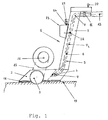
- the equipment set comprises a material-removing device, as shown in Fig. 1 is designed as a tiller 1.
- the Tiller has a relatively flat bottom section 2, the one Housing to accommodate a wide, not shown in detail Rolling mill 3 forms.
- the suction line consists of a plastic tube 6, on the two ends of two metal knee connectors 7 are attached and extends inside a pillar portion 9 the tiller.
- the suction line 5 is at one end with the Intake manifold 4 and at the other end with one Hose connector 11 connected to the one Suction hose 13 with an inner diameter of 50 mm and one Length up to 100 m is appropriate.
- the milling cutter 3 accommodated in the bottom section 2 is over a V-belt 15 with one on the bottom section 2 supported drive motor 17 connected.
- On the down directed surface of the bottom portion 2 is a circumferential lip seal 18 attached in the attached State of the tiller on the floor surface 19 the interior of the housing with the milling cutter 3 accommodated therein seals airtight on the outside.
- the drive motor can with one in the upper section of the tiller Hand switch 20 can be switched on and off.
- a sensor 21 is installed, which according to externally connected to a differential pressure switch 23.
- a differential pressure switch 23 At the Differential pressure switch 23 are a current-differential pressure connection 24 and a 230/380 volt connection 25.
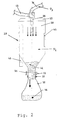
- the suction hose 13 consists of a steel-reinforced plastic and leads to the in Fig. 2 shown pre-separator 27, which is usually in a different room than the tiller shown in Fig. 1 located.
- the pre-separator 27 consists essentially of one Container 28, which at its upper end with a lid 29th is provided.
- the cover 29 has a connecting piece 26 which the suction hose 13 leading to the tiller 1 is attached is.
- a disposal pipe 33 provided with a Sword slide 35 and a bag clamp 37 is equipped.
- the bag clamp is used to attach a disposal container 39 in the form of a flexible sack in which the milled material 41 can be included.
- the inside of the container 27 is with the outside air connected by a false air damper 43.
- On the Side wall of the container 27 is also a sight glass 45 built in, which functions as a level indicator Fulfills.
- the container 28 of the pre-separator 27 is finally by another suction hose 31 with an inner diameter of 70 mm and a length of up to 50 m with that in FIG. 3 shown vacuum unit 47 connected.
- a commercially available vacuum unit 47 is used Vacuum unit with a minimum output of 9.5 KW and with a filter system for the separation of carcinogenic dusts.
- the Filter system consists of a pre-filter, a coarse filter and a fine filter.
- the vacuum unit 47 is switched on, so that the vacuum required to suck off the material removed in the tiller 1 is generated.
- a pressure P 1 is produced in the suction line 5 and thus also in the housing of the bottom section 1.
- a lower pressure (stronger negative pressure) P 2 is produced in the container 28 of the pre-separator 27, which in turn is higher than the pressure P 3 in the suction hose 31 which leads to the negative pressure unit 45.
- P 1 > P 2 > P 3rd Fulfills Due to the all-round, highly abrasion-resistant, 5 mm thick lip seal 19 made of plastic, the pressure losses at the tiller 1 are considerably reduced.
- the motor 17 is switched on and the milling cutter 3 is driven by means of the V-belt 15.
- the surface material such as a pollutant-containing building material, in which asbestos, PCB, or PAH are included as additives to increase the abrasion resistance, is peeled off the floor by means of the diamond-coated milling lamellae and suctioned off in the direction of rotation of the lamellae towards the operator under the influence of the negative pressure P 1 .
- the combination of the knee connections 9 made of steel with the suction line 5 made of plastic ensures that the milled material is forwarded to the pre-separator through the suction line 13 with reduced wear and reduced vibrations.
- the differential pressure measuring device 23 Through the sensor 21 of the differential pressure measuring device 23 it is possible to detect an undesirable increase in pressure and the immediate automatic shutdown of the tiller 1 bring about without operating the hand switch 20 to have to.
- the milled material 41 then passes through the suction hose 13 into the pre-separator 27 shown in FIG. 2 and settles in the bottom section of the container 28.
- the milled material 41 can be metered into the sack 39 located underneath and fastened to the end section of the container 27 by means of the sack clamp 37.
- the filled sack 39 below the pre-separator 27 is removed while the vacuum unit 47 is running, which prevents the milled material from trickling down or contaminated fine dust from escaping from the container 28.
- the level of the milled material 41 can be monitored by the level indicator 45, which is designed here as a sight glass.
- the faulty air damper 43 can be be operated to automatically turn off the tiller 1 if it is determined that a Irregularity in the function of the pre-separator, such as Example, an overfill of the container 28 has occurred.
- the pre-separator is 27 on a mobile stand, not shown in detail Installed.
- Equipment set foreclosure measures the elaborate Keeping rooms under pressure and the use of locks and a water management system.
- the invention is based on the implementation of the above Device system not limited.
- the Tiller for machining edge areas one to one renovating room with an additional router be equipped, also on the suction line 5 connected.
- Another embodiment of the invention Device system is not just at the material-removing device, i.e. on the tiller 1, but also on the pre-separator 27 shown in FIG. 2
- Differential pressure switch with a corresponding, inside the Provide container 27 attached sensor.
- a device set for processing surfaces has one material-removing device (1) and a device thereon connected, together with this a closed one Vacuum unit forming vacuum system (47) for suction of worn surface material.
- the material-removing Device (1) has a differential pressure switch (23) for automatic shutdown of the device when falling below a certain pressure difference between the vacuum system and outside air.
Landscapes
- Engineering & Computer Science (AREA)
- Mechanical Engineering (AREA)
- Road Repair (AREA)
- Working Measures On Existing Buildindgs (AREA)
- Processing Of Solid Wastes (AREA)
- Cleaning In General (AREA)
- Crushing And Pulverization Processes (AREA)
- Grinding-Machine Dressing And Accessory Apparatuses (AREA)
- Coating Apparatus (AREA)
- Threshing Machine Elements (AREA)
Abstract
Description
Die Erfindung bezieht sich auf einen Gerätesatz zur Bearbeitung von Oberflächen, insbesondere auf einen Gerätesatz zur Bearbeitung von kontaminierten Bodenflächen in der Bauwirtschaft.The invention relates to a device set for processing of surfaces, especially on a set of equipment Processing contaminated floor areas in the Construction industry.
Geräte zur materialabtragenden Bearbeitung von Oberflächen sind verschiedentlich bekannt. Insbesondere werden Geräte und Vorrichtungen zum schichtweisen Abtragen von Bodenbelägen in der Bauwirtschaft breit eingesetzt.Devices for the removal of material from surfaces known variously. In particular, devices and Devices for removing layers of floor coverings in widely used in the construction industry.
Aus der Druckschrift DE 198 22 223 A1 ist eine Betonfräse zum Fräsen von, insbesondere beschichteten Beton- oder Estrichböden bekannt. Eine derartige Betonfräse hat einen in einem Fräskopfschacht angeordneten Fräskopf und eine Staubabsaugvorrichtung für die beim Fräsvorgang entstehenden Stäube und Fräsgut. Zur Abschottung des Fräskopfschachts von der Außenluft sind am Gehäuse der Betonfräse angebrachte Dichtlippen und Bürsten vorgesehen.From the publication DE 198 22 223 A1 is a concrete milling machine for Milling, in particular coated concrete or screed floors known. Such a concrete milling machine has one in one Milling head shaft arranged milling head and one Dust extraction device for those arising during the milling process Dusts and milled material. For sealing off the milling head shaft from the outside air are attached to the housing of the concrete milling machine Sealing lips and brushes provided.
Aus der weiteren Druckschrift DE 43 23 222 A1 ist ein Verfahren
und eine Einrichtung zur Füllgradanzeige des Staubfilterbeutels
in einem Staubsauger bekannt. Hierbei handelt es sich im
einzelnen um eine Filterwechselanzeige mit einem Komperator für
den Differenzdruckvergleich, wobei der Komperator mit einer
nachgeschalteten Staubfilterbeutel-Füllgradanzeige verbunden
ist. Eine derartige Anzeige ist dazu geeignet, anzuzeigen, wenn
im Saugbetrieb durch aufgenommenen Feinstaub die Poren des
Staubfilterbeutels zunehmend verstopft werden. Werden luftige
Materialien eingesaugt, so findet ein geringerer Druckabfall im
Inneren des Staubfilterbeutels statt. Dadurch ist es möglich,
mit einfachen Mitteln einerseits eine bessere
Staubfilterausnutzung bei der Aufnahme von Feinstaub ohne
Filterverstopfung zu erreichen, und andererseits beim Saugen
von luftigem Material eine Überfüllung des Filterbeutels zu
vermeiden.
Die Problematik der Verwendung eines Filterbeutels lässt sich
jedoch auf die Eingangs beschriebene Betonfräse nicht
übertragen.From the
However, the problem of using a filter bag cannot be transferred to the concrete milling machine described at the beginning.
Beim Einsatz von Gerätesystemen, die zur Sanierung kontaminierter Bodenflächen verwendet werden, müssen eine staubdichte Abschottung des Sanierungsbereiches sowie eine Raumluftfilterung und Unterdruckhaltung während des Ausbaus der kontaminierten Schichten gemäss der geltenden Normen (TRGS 519) gewährleistet werden. Das ausgebaute, kontaminierte Material muss über Materialschleusen in mehreren Stufen entfernt werden, bevor es den Transportcontainern zugeführt werden kann. Das mit den Arbeiten im kontaminierten Bereich betraute Personal muss im kontaminierten Bereich unter Personenvollschutz mit gebläseunterstützten Masken arbeiten und beim verlassen des Einsatzbereiches über Personalschleusen ein- und ausgeschleust werden. Im Schleusensystem fallen kontaminierte Abwässer an, die über ein Filtersystem dekontaminiert werden müssen. Nicht zuletzt ist zur Durchführung des Verfahrens ein erheblicher Energieaufwand für die Unterdruckhaltung des zu dekontaminierenden Einsatzbereiches und für das Wassermanagement notwendig.When using device systems for renovation contaminated floor surfaces must be used dustproof partitioning of the renovation area as well as a Room air filtering and maintaining negative pressure during removal of the contaminated layers in accordance with the applicable standards (TRGS 519) be guaranteed. The removed, contaminated material must be removed over material locks in several stages, before it can be transported to the shipping containers. That with personnel entrusted with the work in the contaminated area in the contaminated area with full personal protection fan-assisted masks work and when leaving the Application area in and out via personnel locks become. Contaminated waste water accumulates in the lock system, which have to be decontaminated via a filter system. Not Lastly, a significant amount is required to carry out the procedure Energy expenditure for maintaining the vacuum of the decontaminating area of application and for that Water management necessary.
Für das schichtweise Abtragen gemäß dem oben beschriebenen Verfahren wird üblicherweise eine manuell verfahrbare Bodenfräse eingesetzt. Unabhängig und zusätzlich zu der Bodenfräse als Arbeitsgerät sind Material- und Personalschleusen vorgesehen. Ausgehend von diesem Stand der gerätetechnischen Ausrüstung und des bekannten Verfahrens zur Bearbeitung von kontaminierten Bodenflächen werden die oben genannten aufwendige Unterdruckhaltung, zu gewährleistende Abschottungsmaßnahmen und die Notwendigkeit zusätzlicher Ausrüstung für den Personenvollschutz als nachteilig empfunden.For layer-by-layer removal as described above The method is usually a manually movable one Tiller used. Independent and in addition to that Tillers as working tools are material and Staff locks provided. Based on this state of the technical equipment and the known method for Processing contaminated floor areas will be the above mentioned extensive maintenance of negative pressure, to be guaranteed Foreclosure measures and the need for additional Equipment for full personal protection perceived as disadvantageous.
Aufgabe der Erfindung ist es einen Gerätesatz zur Bearbeitung von Oberflächen, insbesondere einen Gerätesatz zur Bearbeitung von kontaminierten Bodenflächen zur Verfügung zu stellen, der ohne komplizierte und aufwendige technische Maßnahmen die erforderliche Sicherheit gewährleistet.The object of the invention is a set of equipment for processing of surfaces, in particular a set of equipment for processing of contaminated floor space to provide the without complicated and time-consuming technical measures required security guaranteed.
Diese Aufgabe wird durch ein Gerätesystem gemäß der im Anspruch 1 definierten Merkmalskombination gelöst. Vorteilhafte Weiterbildungen der Erfindung sind in den Unteransprüchen definiert.This task is performed by a device system according to the claim 1 defined combination of features solved. Beneficial Further developments of the invention are in the subclaims Are defined.
Die Erfindung wird im folgenden anhand eines Ausführungsbeispiels näher erläutert.The invention is based on a Embodiment explained in more detail.
Es zeigen:
Im Ausführungsbeispiel der Erfindung umfaßt der Gerätesatz eine
materialabtragende Vorrichtung, die gemäß der Darstellung in
Fig. 1 als Bodenfräse 1 ausgeführt ist. Als eine solche
Bodenfräse wird hier eine Estrich-Fräsmaschine eingesetzt. Die
Bodenfräse hat einen relativ flachen Bodenabschnitt 2, der ein
Gehäuse zur Aufnahme eines nicht im einzelnen gezeigten breiten
Walzenfräsers 3 bildet. Am Gehäuse ist ein Ansaugstutzen 4
gasdicht angebracht, der mit einer Saugleitung 5 verbunden ist.
Die Saugleitung besteht aus einem Kunststoffrohr 6, an dessen
beiden Enden zwei Knieverbindungsstücke 7 aus Metall angebracht
sind, und erstreckt sich im Inneren eines Säulenabschnitts 9
der Bodenfräse. Die Saugleitung 5 ist an einem Ende mit dem
Ansaugstutzen 4 und an anderem Ende mit einem
Schlauchverbindungsstutzen 11 verbunden, an dem ein
Saugschlauch 13 mit einem Innendurchmesser von 50 mm und einer
Länge bis zu 100 m angebracht ist.In the exemplary embodiment of the invention, the equipment set comprises a
material-removing device, as shown in
Fig. 1 is designed as a tiller 1. As such
A screed milling machine is used here. The
Tiller has a relatively
Der im Bodenabschnitt 2 untergebrachte Walzenfräser 3 ist über
einen Keilriemen 15 mit einem auf dem Bodenabschnitt 2
abgestützten Antriebsmotor 17 verbunden. An der nach unten
gerichteten Oberfläche des Bodenabschnitts 2 ist eine
umlaufende Lippendichtung 18 angebracht, die im aufgesetzten
Zustand der Bodenfräse auf der Bodenoberfläche 19 den Innenraum
des Gehäuses mit dem darin aufgenommenen Walzenfräser 3 nach
außen hin luftdicht abschließt. Der Antriebsmotor kann mit
einem im oberen Abschnitt der Bodenfräse befindlichen
Handschalter 20 ein- und ausgeschaltet werden.The
In der Saugleitung 5 ist ein Messfühler 21 eingebaut, der nach
außen hin mit einem Differenzdruckschalter 23 verbunden ist. Am
Differenzdruckschalter 23 befinden sich ein Strom-Differenz-Druck-Anschluss
24 sowie ein 230/380 Volt-Anschluss 25.In the
In diesem Ausführungsbeispiel sind die Schneidkanten des
breiten Walzenfräsers 3 mit Diamant beschichtet, so daß mit
diesem Walzenfräser sehr dünne Schichten von der
Bodenoberfläche abgetragen werden können. Der Saugschlauch 13
besteht aus einem stahlarmierten Kunststoff und führt zu dem in
Fig. 2 gezeigten Vorabscheider 27, der sich in der Regel in
einem anderen Raum als die in Fig. 1 gezeigte Bodenfräse
befindet.In this embodiment, the cutting edges of the
Der Vorabscheider 27 betsteht im wesentlichen aus einem
Behälter 28, der an seinem oberen Ende mit einem Deckel 29
versehen ist. Der Deckel 29 hat einen Anschlussstutzen 26, an
dem der zu der Bodenfräse 1 führende Saugschlauch 13 angebracht
ist. Am unteren konisch zulaufenden Ende des Behälters 28 ist
ein Entsorgungsrohr 33 versehen, welches mit einem
Schwertschieber 35 sowie einer Sackklemme 37 ausgestattet ist.
Die Sackklemme dient zur Anbringung eines Entsorgungsbehälters
39 in Form eines flexiblen Sacks, in dem das Fräsgut 41
aufgenommen werden kann. Das Innere des Behälters 27 ist mit
der Außenluft durch eine Fehlluftklappe 43 verbunden. Auf der
Seitenwand des Behälters 27 ist außerdem ein Schauglas 45
eingebaut, das die Funktion einer Füllstand-Anzeigevorrichtung
erfüllt. Der Behälter 28 des Vorabscheiders 27 ist schließlich
durch einen weiteren Saugschlauch 31 mit einem Innendurchmesser
von 70 mm und einer Länge bis zu 50 m mit der in Fig. 3
gezeigten Unterdruckeinheit 47 verbunden.The pre-separator 27 consists essentially of one
Als Unterdruckeinheit 47 dient ein handelsübliches
Unterdruckaggregat mit einer Mindestleistung von 9,5 KW und mit
einem Filtersystem zum Abscheiden von kanzerogenen Stäuben. Das
Filtersystem besteht aus einem Vorfilter, einem Grobfilter und
einem Feinstfilter.A commercially
Die Funktionsweise des aus den obengenannten Einheiten bestehenden und ein geschlossenes Unterdrucksystem bildenden Gerätesatzes zur Bearbeitung von Bodenflächen wird nachfolgend erläutert.The operation of the from the above units existing and forming a closed vacuum system Equipment set for processing floor surfaces is shown below explained.
Zunächst wird die Unterdruckeinheit 47 eingeschaltet, damit der
zum Absaugen des in der Bodenfräse 1 abgetragenen Materials
notwendige Unterdruck erzeugt wird. Dabei wird durch die
Verbindung der Unterdruckeinheit 47 mit der Bodenfräse 1
mittels der Schläuche 31 und 13 unter Zwischenschaltung des
Vorabscheiders ein Druck P1 in der Saugleitung 5 und somit auch
im Gehäuse des Bodenabschnitts 1 hergestellt. Entsprechend der
besonderen Anordnung des Gerätesatzes wird in dem Behälter 28
des Vorabscheiders 27 ein niedrigerer Druck (stärkerer
Unterdruck) P2 hergestellt, der wiederum höher als der Druck P3
in dem Saugschlauch 31 ist, der zu der Unterdruckeinheit 45
führt. Auf diese Weise ist die Ungleichung
Durch anschließendes Betätigen des Handschalters 20 wird der
Motor 17 eingeschaltet und der Walzenfräser 3 mittels des
Keilriemens 15 angetrieben. Die dadurch erzielte Rotation des
Walzenfräsers bewirkt kombiniert mit einer gleitenden Bewegung
des Bodenabschnitts 2 ein schichtweises Abtragen von Material
von der Bodenoberfläche 19 führt. Durch Regulierung der Höhe
des Walzenfräsers 3 im Bodenabschnitt 1 kann die Dicke der
abgetragenen Bodenschicht eingestellt werden. Das
Oberflächenmaterial, wie beispielsweise ein schadstoffhaltiger
Baustoff, in dem Asbest, PCB, oder PAK als Zuschlagstoffe zur
Erhöhung der Abriebsfestigkeit enthalten sind, wird mittels der
diamantbeschichteten Fräslamellen vom Boden abgeschält und in
Drehrichtung der Lamellen zum Bediener hin unter Einwirkung des
Unterdrucks P1 abgesaugt. Dabei wird durch die Kombination der
Knieverbindungen 9 aus Stahl mit der aus Kunststoff gefertigten
Saugleitung 5 eine Weiterleitung des Fräsguts zum Vorabscheider
durch die Saugleitung 13 unter geminderten Verschleiß und
geringere Vibrationen gewährleistet.By subsequently operating the
Durch den Messfühler 21 der Differentialdruckmessvorrichtung 23
ist es möglich, einen unerwünschten Druckanstieg festzustellen
und die sofortige automatische Abschaltung der Bodenfräse 1
herbeizuführen, ohne dafür den Handschalter 20 betätigen zu
müssen. Die Empfindlichkeit, bei der der Differenzdruckschalter
23 anspricht liegt bei einer Druckdifferenz von 10 mbar, wobei
diese Druckdifferenz einstellbar ist. Bei Bedarf kann die
Druckdifferenz insbesondere in Abhängigkeit von der Leistung
der Unterdruckeinheit 45 und der Beschaffenheit der
Unterdruckschläuche 13, 31 und des Vorabscheiders 27
eingestellt werden. Durch eine derartige automatische
Abschaltung bei Ausfall oder Leckage kann eine Kontamination
des Umfeldes wirksam ausgeschlossen werden.Through the
Das Fräsgut 41 gelangt anschließend über den Saugschlauch 13 in
den in Fig. 2 gezeigten Vorabscheider 27 und setzt sich im
Bodenabschnitt des Behälters 28 ab. Durch Betätigung des
Schwertschiebers 35 kann das Fräsgut 41 dosiert in den darunter
befindlichen, mittels der Sackklemme 37 am Endabschnitt des
Behälters 27 befestigten Sack 39 abgefüllt werden. Die Entnahme
des abgefüllten Sacks 39 unterhalb des Vorabscheiders 27
erfolgt bei laufender Unterdruckeinheit 47, wodurch ein
Nachrieseln von Fräsgut oder ein Austritt von kontaminiertem
Feinstaub aus dem Behälter 28 ausgeschlossen ist.
Das Niveau des Fräsgutes 41 kann dabei durch die
Füllstandanzeigeeinrichtung 45, die hier als Schauglas
ausgeführt ist, überwacht werden.The milled
The level of the milled
Am Vorabscheider 27 kann bei Bedarf die Fehlluftklappe 43
betätigt werden, um die automatische Abschaltung der Bodenfräse
1 zu bewirken, wenn festgestellt wird, dass eine
Unregelmäßigkeit in der Funktion des Vorabscheiders, wie zum
Beispiel eine Überfüllung des Behälters 28, eingetreten ist.On the pre-separator 27, the
Im vorliegenden Ausführungsbeispiel ist der Vorabscheider 27 auf einem nicht im einzelnen gezeigten, fahrbaren Ständer installiert.In the present exemplary embodiment, the pre-separator is 27 on a mobile stand, not shown in detail Installed.
Wie anhand des oben beschriebenen Ausführungsbeispiels zu erkennen ist können durch die Anwendung des erfindungsgemäßen Gerätesatzes Abschottungsmaßnahmen, die aufwendige Unterdruckhaltung von Räumen sowie die Verwendung von Schleusen und eines Wassermanagementsystems wegfallen. Außerdem ist es möglich durch die Verwendung des diamantbeschichteten Walzenfräsers dünne Schichten bis zum Erreichen des unkontaminierten Baustoffs abzutragen, woraus eine Verringerung der Abfallmengen resultiert. Ein wesentlicher Vorteil besteht auch im Wegfall von Zulagen für Arbeiten unter Vollschutz, in der Reduzierung von vorbereitenden Maßnahmen, der Verkürzung von Zeiten für Baustelleinrichtung und -abbau sowie in der Verringerung des Personalaufwandes.As with the embodiment described above can be recognized by the application of the invention Equipment set foreclosure measures, the elaborate Keeping rooms under pressure and the use of locks and a water management system. Besides, it is possible by using the diamond coated Roller mill thin layers until reaching the remove uncontaminated building material, resulting in a reduction of waste amounts results. There is a major advantage also in the absence of allowances for work under full protection, in the reduction of preparatory measures, the shortening of times for construction site set-up and dismantling as well as in the Reduction in personnel expenses.
Zusätzlich zu den wirtschaftlichen Vorteilen hat das erfindungsgemäße Gerätesystem auch wesentliche ökologische Vorteile. Diese bestehen unter anderem in der Reduzierung der Mengen an kontaminiertem Abfall, zu dem nicht nur die ausgebauten kontaminierten Baumaterialien, sondern auch das gesamte kontaminierte Abschottungsmaterial, Schutzausrüstung, Schleusenbaumaterial, Abluftfilter, etc. zählen. Auch die Entstehung von kontaminierten Abwässern wird durch die Anwendung des erfindungsgemäßen Gerätesatzes vermieden.In addition to the economic benefits, that has Device system according to the invention also essential ecological Benefits. These consist, among other things, in reducing the Amounts of contaminated waste that not only include removed contaminated building materials, but also that all contaminated foreclosure material, protective equipment, Lock material, exhaust filter, etc. count. Also the Contamination of waste water is caused by the Avoid application of the equipment set according to the invention.
Die Erfindung ist auf die Ausführung des oben beschriebenen
Gerätesystems nicht beschränkt. So zum Beispiel kann die
Bodenfräse zur Bearbeitung von Randbereichen eines zu
sanierenden Raumes mit einer zusätzlichen Randfräse
ausgestattet werden, die ebenfalls an der Saugleitung 5
angeschlossen ist. Es ist auch möglich, mehrere Fräsaggregate,
zum Beispiel verschiedenartige Fräsen als selbstständige
Einheiten zum Abtragen von Oberflächenmaterial, an den in Fig.
2 gezeigten Vorabscheider 27 anzuschließen. Bei einer
derartigen Ausführung muss jedoch die Leistung der
Unterdruckeinheit entsprechend erhöht werden, ohne dadurch das
Funktionsprinzip des vorliegenden geschlossenen
Unterdrucksystems zu verändern.The invention is based on the implementation of the above
Device system not limited. For example, the
Tiller for machining edge areas one to one
renovating room with an additional router
be equipped, also on the
Eine weitere Ausführungsform der erfindungsgemäßen
Gerätesystems besteht darin, nicht nur an der
materialabtragenden Vorrichtung, d.h. an der Bodenfräse 1,
sondern auch an den in Fig. 2 gezeigten Vorabscheider 27 einen
Differenzdruckschalter mit einem entsprechenden, im Inneren des
Behälters 27 angebrachten Messfühler vorzusehen. Beim Ausfall
Ein Gerätesatz zur Bearbeitung von Oberflächen hat eine
materialabtragende Vorrichtung (1) und eine daran
angeschlossene, mit dieser zusammen ein geschlossenes
Unterdrucksystem bildende Unterdruckeinheit (47) zum Absaugen
von abgetragenem Oberflächenmaterial. Die materialabtragende
Vorrichtung (1) hat einen Differenzdruckschalter (23) zum
selbsttätigen Abschalten der Vorrichtung beim Unterschreiten
einer bestimmten Druckdifferenz zwischen dem Unterdrucksystem
und Außenluft.Another embodiment of the invention
Device system is not just at the
material-removing device, i.e. on the tiller 1,
but also on the pre-separator 27 shown in FIG. 2
Differential pressure switch with a corresponding, inside the
Provide
Claims (12)
Applications Claiming Priority (2)
| Application Number | Priority Date | Filing Date | Title |
|---|---|---|---|
| DE10012182 | 2000-03-13 | ||
| DE10012182A DE10012182C1 (en) | 2000-03-13 | 2000-03-13 | Surface treatment device for contaminated floor surface has differential pressure switch monitoring suction system for extraction of removed material for safety shut-down |
Publications (2)
| Publication Number | Publication Date |
|---|---|
| EP1136174A1 true EP1136174A1 (en) | 2001-09-26 |
| EP1136174B1 EP1136174B1 (en) | 2005-08-17 |
Family
ID=7634544
Family Applications (1)
| Application Number | Title | Priority Date | Filing Date |
|---|---|---|---|
| EP01106039A Expired - Lifetime EP1136174B1 (en) | 2000-03-13 | 2001-03-12 | Equipment for working surfaces |
Country Status (4)
| Country | Link |
|---|---|
| EP (1) | EP1136174B1 (en) |
| AT (1) | ATE302091T1 (en) |
| DE (2) | DE10012182C1 (en) |
| ES (1) | ES2248180T3 (en) |
Cited By (3)
| Publication number | Priority date | Publication date | Assignee | Title |
|---|---|---|---|---|
| EP2946710A3 (en) * | 2014-05-20 | 2016-02-24 | Festool GmbH | Manually operated machine tool with a particle discharge connection |
| EP3678786A4 (en) * | 2017-09-05 | 2021-06-02 | Husqvarna AB | Separator and method of operating a separator |
| WO2021165521A1 (en) | 2020-02-21 | 2021-08-26 | Fraunhofer-Gesellschaft zur Förderung der angewandten Forschung eingetragener Verein | Device and method for removing material from fibre-composite materials, in particular for scarfing |
Families Citing this family (5)
| Publication number | Priority date | Publication date | Assignee | Title |
|---|---|---|---|---|
| DE102007059930B3 (en) * | 2007-12-04 | 2009-02-19 | Kurz, Gerhard | Motor performance controlling or regulating device for cylinder vacuum cleaner, has regulating device formed such that motor is switched off for preset time period when rise rate of low pressure exceeds preset value |
| NL2012364B1 (en) * | 2014-03-05 | 2015-12-03 | Blastrac B V | Grinding machine and method for grinding a floor surface. |
| DE102014014373B4 (en) * | 2014-10-02 | 2016-05-04 | deconta GmbH | Method for extracting sanding dust and suction device |
| CN106141795A (en) * | 2016-08-03 | 2016-11-23 | 长葛市世军机械加工厂 | Bits device rolled up by lathe for machining |
| FR3067273A1 (en) * | 2017-06-07 | 2018-12-14 | M.B.H. Developpement | SECURED USE SURFACE DEVICE |
Citations (12)
| Publication number | Priority date | Publication date | Assignee | Title |
|---|---|---|---|---|
| GB100817A (en) * | 1916-01-06 | 1916-07-13 | Donald Fraser | Apparatus for Removing Dust and the like in the Operation of Stone-cutting and other Tools. |
| DE1777147A1 (en) * | 1967-09-14 | 1971-04-01 | Phillips Drill Co | Percussion hammer |
| US3608968A (en) * | 1969-04-03 | 1971-09-28 | Christensen Diamond Prod Co | Pavement cutting and water and cutting pickup apparatus |
| GB1259898A (en) * | 1969-05-12 | 1972-01-12 | Tac Construction Materials Ltd | Improvements in apparatus for stripping insulating coatings |
| EP0022435A1 (en) * | 1979-07-06 | 1981-01-14 | Fläkt Aktiebolag | Evacuation system for particulate waste material |
| DE3000390A1 (en) * | 1980-01-08 | 1981-07-09 | Günter 7155 Oppenweiler Lind | Tongue and groove cutting machine for industrial flooring - has extraction hood over cutter connected via suction fan to sawdust bag |
| DE3219391A1 (en) * | 1982-05-24 | 1983-11-24 | Guido Oberdorfer Wap-Maschinen, 7919 Bellenberg | Vacuum cleaner |
| JPS62277253A (en) * | 1986-05-23 | 1987-12-02 | Sato Kogyo Co Ltd | Polluted concrete surface grinder |
| US4923251A (en) * | 1988-04-04 | 1990-05-08 | Sato Kogyo Co., Ltd. | Apparatus for removing asbestos and like materials from a surface |
| EP0377100A1 (en) * | 1988-12-30 | 1990-07-11 | C. & E. FEIN GmbH & Co. | Vacuum cleaner and dust-free working tool |
| DE4238564A1 (en) * | 1992-11-14 | 1994-05-19 | Fein C & E | Electric power-driven tool cooled by suction of air through motor - is switched off automatically by disconnection of vacuum hose or insufficiency of vacuum in cooling-air extn. tube |
| DE19822223A1 (en) * | 1998-05-18 | 1999-12-02 | Kaefer Isoliertechnik | Mortising machine for especially coated concrete or plaster floors |
Family Cites Families (1)
| Publication number | Priority date | Publication date | Assignee | Title |
|---|---|---|---|---|
| DE4323222C2 (en) * | 1993-07-12 | 2002-05-02 | Miele & Cie | Method and device for displaying the degree of filling of the dust filter bag in a vacuum cleaner |
-
2000
- 2000-03-13 DE DE10012182A patent/DE10012182C1/en not_active Expired - Fee Related
-
2001
- 2001-03-12 AT AT01106039T patent/ATE302091T1/en active
- 2001-03-12 EP EP01106039A patent/EP1136174B1/en not_active Expired - Lifetime
- 2001-03-12 DE DE50107088T patent/DE50107088D1/en not_active Expired - Lifetime
- 2001-03-12 ES ES01106039T patent/ES2248180T3/en not_active Expired - Lifetime
Patent Citations (12)
| Publication number | Priority date | Publication date | Assignee | Title |
|---|---|---|---|---|
| GB100817A (en) * | 1916-01-06 | 1916-07-13 | Donald Fraser | Apparatus for Removing Dust and the like in the Operation of Stone-cutting and other Tools. |
| DE1777147A1 (en) * | 1967-09-14 | 1971-04-01 | Phillips Drill Co | Percussion hammer |
| US3608968A (en) * | 1969-04-03 | 1971-09-28 | Christensen Diamond Prod Co | Pavement cutting and water and cutting pickup apparatus |
| GB1259898A (en) * | 1969-05-12 | 1972-01-12 | Tac Construction Materials Ltd | Improvements in apparatus for stripping insulating coatings |
| EP0022435A1 (en) * | 1979-07-06 | 1981-01-14 | Fläkt Aktiebolag | Evacuation system for particulate waste material |
| DE3000390A1 (en) * | 1980-01-08 | 1981-07-09 | Günter 7155 Oppenweiler Lind | Tongue and groove cutting machine for industrial flooring - has extraction hood over cutter connected via suction fan to sawdust bag |
| DE3219391A1 (en) * | 1982-05-24 | 1983-11-24 | Guido Oberdorfer Wap-Maschinen, 7919 Bellenberg | Vacuum cleaner |
| JPS62277253A (en) * | 1986-05-23 | 1987-12-02 | Sato Kogyo Co Ltd | Polluted concrete surface grinder |
| US4923251A (en) * | 1988-04-04 | 1990-05-08 | Sato Kogyo Co., Ltd. | Apparatus for removing asbestos and like materials from a surface |
| EP0377100A1 (en) * | 1988-12-30 | 1990-07-11 | C. & E. FEIN GmbH & Co. | Vacuum cleaner and dust-free working tool |
| DE4238564A1 (en) * | 1992-11-14 | 1994-05-19 | Fein C & E | Electric power-driven tool cooled by suction of air through motor - is switched off automatically by disconnection of vacuum hose or insufficiency of vacuum in cooling-air extn. tube |
| DE19822223A1 (en) * | 1998-05-18 | 1999-12-02 | Kaefer Isoliertechnik | Mortising machine for especially coated concrete or plaster floors |
Non-Patent Citations (1)
| Title |
|---|
| PATENT ABSTRACTS OF JAPAN vol. 012, no. 160 (M - 697) 14 May 1988 (1988-05-14) * |
Cited By (6)
| Publication number | Priority date | Publication date | Assignee | Title |
|---|---|---|---|---|
| EP2946710A3 (en) * | 2014-05-20 | 2016-02-24 | Festool GmbH | Manually operated machine tool with a particle discharge connection |
| EP3678786A4 (en) * | 2017-09-05 | 2021-06-02 | Husqvarna AB | Separator and method of operating a separator |
| US11185808B2 (en) | 2017-09-05 | 2021-11-30 | Husqvarna Ab | Separator and method of operating a separator |
| AU2018330396B2 (en) * | 2017-09-05 | 2023-08-17 | Husqvarna Ab | Separator and method of operating a separator |
| WO2021165521A1 (en) | 2020-02-21 | 2021-08-26 | Fraunhofer-Gesellschaft zur Förderung der angewandten Forschung eingetragener Verein | Device and method for removing material from fibre-composite materials, in particular for scarfing |
| DE102020104689A1 (en) | 2020-02-21 | 2021-08-26 | Fraunhofer-Gesellschaft zur Förderung der angewandten Forschung eingetragener Verein | Device and method for material removal from fiber composite materials, in particular for shafts |
Also Published As
| Publication number | Publication date |
|---|---|
| ES2248180T3 (en) | 2006-03-16 |
| DE10012182C1 (en) | 2001-08-09 |
| ATE302091T1 (en) | 2005-09-15 |
| EP1136174B1 (en) | 2005-08-17 |
| DE50107088D1 (en) | 2005-09-22 |
Similar Documents
| Publication | Publication Date | Title |
|---|---|---|
| DE2758038C3 (en) | Extraction device | |
| DE102008027050A1 (en) | Method and device for automatic edge grinding of glass plates under clean room conditions | |
| DE102014210947B3 (en) | Apparatus and method for removing contaminated material | |
| DE10012182C1 (en) | Surface treatment device for contaminated floor surface has differential pressure switch monitoring suction system for extraction of removed material for safety shut-down | |
| DE202008007615U1 (en) | Device for automatic edge grinding of glass plates under cleanroom conditions | |
| EP3881923B1 (en) | Aerosol separator and method for installing a coalescence filter element in an aerosol separator | |
| EP0413129A2 (en) | Removal method and apparatus for fluids containing production residues | |
| DE3800050A1 (en) | Extraction method for pulverulent machining waste | |
| DE19810912A1 (en) | Suction and discharge device for a rinsing liquid | |
| DE202015009698U1 (en) | Filter system for the filtration of, in particular contaminated, air dusts | |
| EP3002081A2 (en) | Method for exhausting grinding dust and suction device | |
| DE3337549C2 (en) | ||
| DE102014013129B4 (en) | Machine tool for machining a workpiece by means of minimal quantity lubrication and method for cleaning such a machine tool | |
| EP2853366A1 (en) | Method for the production of a core sample in soils contaminated by hazardous materials and device for implementing such a method | |
| DE102020133149B4 (en) | Dedusting device with a controller for at least two operating modes and method for controlling a dedusting device | |
| DE10047443C2 (en) | Method and device for removing floor coverings | |
| DE202019101323U1 (en) | Device for dismantling contaminated building material layers | |
| EP4103348A1 (en) | Device and system for covering a cut gap which can be produced by a machine tool, and method for suctioning dust out of a working area of a machine tool | |
| DE29920718U1 (en) | Arrangement and device for separating a radioactive component of a nuclear reactor | |
| DE4108782C1 (en) | Contamination-free exchange of asbestos contg. fire protection flaps - includes sepg. ventilation segments, applying sealant around air channel installing stack and sepn. unit, placing flap in sack, vacuuming partitioned areas, etc. | |
| DE10047274A1 (en) | Cyclone preliminary collector for separating the greatest part of grinding splinters appearing on wall chase cutters during the cutting of wiring channels in walls fits into a tube system for sucking off grinding dust. | |
| EP1361941B1 (en) | Method for removing an outer layer of masonry and device for removing the outer layer of especially joint mortar | |
| DE102006009965B4 (en) | Extraction system for a machining machine | |
| EP4015723A1 (en) | Atmosphere separation apparatus and method thereof | |
| DE19523549A1 (en) | Pipe and container wall de-contamination system |
Legal Events
| Date | Code | Title | Description |
|---|---|---|---|
| PUAI | Public reference made under article 153(3) epc to a published international application that has entered the european phase |
Free format text: ORIGINAL CODE: 0009012 |
|
| AK | Designated contracting states |
Kind code of ref document: A1 Designated state(s): AT BE CH CY DE DK ES FI FR GB GR IE IT LI LU MC NL PT SE TR |
|
| AX | Request for extension of the european patent |
Free format text: AL;LT;LV;MK;RO;SI |
|
| 17P | Request for examination filed |
Effective date: 20020326 |
|
| AKX | Designation fees paid |
Free format text: AT BE CH CY DE DK ES FI FR GB GR IE IT LI LU MC NL PT SE TR |
|
| 17Q | First examination report despatched |
Effective date: 20040202 |
|
| GRAP | Despatch of communication of intention to grant a patent |
Free format text: ORIGINAL CODE: EPIDOSNIGR1 |
|
| GRAS | Grant fee paid |
Free format text: ORIGINAL CODE: EPIDOSNIGR3 |
|
| GRAA | (expected) grant |
Free format text: ORIGINAL CODE: 0009210 |
|
| AK | Designated contracting states |
Kind code of ref document: B1 Designated state(s): AT BE CH CY DE DK ES FI FR GB GR IE IT LI LU MC NL PT SE TR |
|
| PG25 | Lapsed in a contracting state [announced via postgrant information from national office to epo] |
Ref country code: IE Free format text: LAPSE BECAUSE OF FAILURE TO SUBMIT A TRANSLATION OF THE DESCRIPTION OR TO PAY THE FEE WITHIN THE PRESCRIBED TIME-LIMIT Effective date: 20050817 Ref country code: NL Free format text: LAPSE BECAUSE OF FAILURE TO SUBMIT A TRANSLATION OF THE DESCRIPTION OR TO PAY THE FEE WITHIN THE PRESCRIBED TIME-LIMIT Effective date: 20050817 Ref country code: GB Free format text: LAPSE BECAUSE OF FAILURE TO SUBMIT A TRANSLATION OF THE DESCRIPTION OR TO PAY THE FEE WITHIN THE PRESCRIBED TIME-LIMIT Effective date: 20050817 Ref country code: TR Free format text: LAPSE BECAUSE OF FAILURE TO SUBMIT A TRANSLATION OF THE DESCRIPTION OR TO PAY THE FEE WITHIN THE PRESCRIBED TIME-LIMIT Effective date: 20050817 Ref country code: FI Free format text: LAPSE BECAUSE OF FAILURE TO SUBMIT A TRANSLATION OF THE DESCRIPTION OR TO PAY THE FEE WITHIN THE PRESCRIBED TIME-LIMIT Effective date: 20050817 |
|
| REG | Reference to a national code |
Ref country code: GB Ref legal event code: FG4D Free format text: NOT ENGLISH |
|
| REG | Reference to a national code |
Ref country code: CH Ref legal event code: EP |
|
| REG | Reference to a national code |
Ref country code: IE Ref legal event code: FG4D Free format text: LANGUAGE OF EP DOCUMENT: GERMAN |
|
| REF | Corresponds to: |
Ref document number: 50107088 Country of ref document: DE Date of ref document: 20050922 Kind code of ref document: P |
|
| PG25 | Lapsed in a contracting state [announced via postgrant information from national office to epo] |
Ref country code: SE Free format text: LAPSE BECAUSE OF FAILURE TO SUBMIT A TRANSLATION OF THE DESCRIPTION OR TO PAY THE FEE WITHIN THE PRESCRIBED TIME-LIMIT Effective date: 20051117 Ref country code: DK Free format text: LAPSE BECAUSE OF FAILURE TO SUBMIT A TRANSLATION OF THE DESCRIPTION OR TO PAY THE FEE WITHIN THE PRESCRIBED TIME-LIMIT Effective date: 20051117 Ref country code: GR Free format text: LAPSE BECAUSE OF FAILURE TO SUBMIT A TRANSLATION OF THE DESCRIPTION OR TO PAY THE FEE WITHIN THE PRESCRIBED TIME-LIMIT Effective date: 20051117 |
|
| PG25 | Lapsed in a contracting state [announced via postgrant information from national office to epo] |
Ref country code: PT Free format text: LAPSE BECAUSE OF FAILURE TO SUBMIT A TRANSLATION OF THE DESCRIPTION OR TO PAY THE FEE WITHIN THE PRESCRIBED TIME-LIMIT Effective date: 20060117 |
|
| NLV1 | Nl: lapsed or annulled due to failure to fulfill the requirements of art. 29p and 29m of the patents act | ||
| REG | Reference to a national code |
Ref country code: CH Ref legal event code: NV Representative=s name: E. BLUM & CO. PATENTANWAELTE |
|
| GBV | Gb: ep patent (uk) treated as always having been void in accordance with gb section 77(7)/1977 [no translation filed] |
Effective date: 20050817 |
|
| REG | Reference to a national code |
Ref country code: ES Ref legal event code: FG2A Ref document number: 2248180 Country of ref document: ES Kind code of ref document: T3 |
|
| REG | Reference to a national code |
Ref country code: IE Ref legal event code: FD4D |
|
| PG25 | Lapsed in a contracting state [announced via postgrant information from national office to epo] |
Ref country code: MC Free format text: LAPSE BECAUSE OF NON-PAYMENT OF DUE FEES Effective date: 20060331 Ref country code: LU Free format text: LAPSE BECAUSE OF NON-PAYMENT OF DUE FEES Effective date: 20060331 |
|
| ET | Fr: translation filed | ||
| PLBE | No opposition filed within time limit |
Free format text: ORIGINAL CODE: 0009261 |
|
| STAA | Information on the status of an ep patent application or granted ep patent |
Free format text: STATUS: NO OPPOSITION FILED WITHIN TIME LIMIT |
|
| 26N | No opposition filed |
Effective date: 20060518 |
|
| REG | Reference to a national code |
Ref country code: CH Ref legal event code: PFA Owner name: SCHAFFER, KARL Free format text: SCHAFFER, KARL#WITTELBACHER STRASSE 2#82319 STARNBERG (DE) -TRANSFER TO- SCHAFFER, KARL#WITTELBACHER STRASSE 2#82319 STARNBERG (DE) |
|
| PG25 | Lapsed in a contracting state [announced via postgrant information from national office to epo] |
Ref country code: CY Free format text: LAPSE BECAUSE OF FAILURE TO SUBMIT A TRANSLATION OF THE DESCRIPTION OR TO PAY THE FEE WITHIN THE PRESCRIBED TIME-LIMIT Effective date: 20050817 |
|
| PGFP | Annual fee paid to national office [announced via postgrant information from national office to epo] |
Ref country code: FR Payment date: 20120403 Year of fee payment: 12 Ref country code: CH Payment date: 20120323 Year of fee payment: 12 |
|
| PGFP | Annual fee paid to national office [announced via postgrant information from national office to epo] |
Ref country code: BE Payment date: 20120323 Year of fee payment: 12 Ref country code: IT Payment date: 20120324 Year of fee payment: 12 |
|
| PGFP | Annual fee paid to national office [announced via postgrant information from national office to epo] |
Ref country code: DE Payment date: 20120329 Year of fee payment: 12 |
|
| PGFP | Annual fee paid to national office [announced via postgrant information from national office to epo] |
Ref country code: AT Payment date: 20120321 Year of fee payment: 12 |
|
| PGFP | Annual fee paid to national office [announced via postgrant information from national office to epo] |
Ref country code: ES Payment date: 20120326 Year of fee payment: 12 |
|
| BERE | Be: lapsed |
Owner name: *SCHAFFER KARL Effective date: 20130331 |
|
| REG | Reference to a national code |
Ref country code: CH Ref legal event code: PL |
|
| REG | Reference to a national code |
Ref country code: AT Ref legal event code: MM01 Ref document number: 302091 Country of ref document: AT Kind code of ref document: T Effective date: 20130312 |
|
| REG | Reference to a national code |
Ref country code: FR Ref legal event code: ST Effective date: 20131129 |
|
| REG | Reference to a national code |
Ref country code: DE Ref legal event code: R119 Ref document number: 50107088 Country of ref document: DE Effective date: 20131001 |
|
| PG25 | Lapsed in a contracting state [announced via postgrant information from national office to epo] |
Ref country code: BE Free format text: LAPSE BECAUSE OF NON-PAYMENT OF DUE FEES Effective date: 20130331 Ref country code: LI Free format text: LAPSE BECAUSE OF NON-PAYMENT OF DUE FEES Effective date: 20130331 Ref country code: DE Free format text: LAPSE BECAUSE OF NON-PAYMENT OF DUE FEES Effective date: 20131001 Ref country code: CH Free format text: LAPSE BECAUSE OF NON-PAYMENT OF DUE FEES Effective date: 20130331 Ref country code: FR Free format text: LAPSE BECAUSE OF NON-PAYMENT OF DUE FEES Effective date: 20130402 Ref country code: AT Free format text: LAPSE BECAUSE OF NON-PAYMENT OF DUE FEES Effective date: 20130312 |
|
| PG25 | Lapsed in a contracting state [announced via postgrant information from national office to epo] |
Ref country code: IT Free format text: LAPSE BECAUSE OF NON-PAYMENT OF DUE FEES Effective date: 20130312 |
|
| REG | Reference to a national code |
Ref country code: ES Ref legal event code: FD2A Effective date: 20140606 |
|
| PG25 | Lapsed in a contracting state [announced via postgrant information from national office to epo] |
Ref country code: ES Free format text: LAPSE BECAUSE OF NON-PAYMENT OF DUE FEES Effective date: 20130313 |