EP1136113B1 - Fibrous filter media - Google Patents
Fibrous filter media Download PDFInfo
- Publication number
- EP1136113B1 EP1136113B1 EP01105393A EP01105393A EP1136113B1 EP 1136113 B1 EP1136113 B1 EP 1136113B1 EP 01105393 A EP01105393 A EP 01105393A EP 01105393 A EP01105393 A EP 01105393A EP 1136113 B1 EP1136113 B1 EP 1136113B1
- Authority
- EP
- European Patent Office
- Prior art keywords
- flow direction
- pleats
- fibers
- filter element
- filter
- Prior art date
- Legal status (The legal status is an assumption and is not a legal conclusion. Google has not performed a legal analysis and makes no representation as to the accuracy of the status listed.)
- Expired - Lifetime
Links
- 239000000835 fiber Substances 0.000 claims description 129
- 239000002245 particle Substances 0.000 claims description 99
- 239000012530 fluid Substances 0.000 claims description 70
- 230000001965 increasing effect Effects 0.000 claims description 43
- 238000011045 prefiltration Methods 0.000 claims description 38
- 238000010276 construction Methods 0.000 claims description 27
- 238000001914 filtration Methods 0.000 claims description 25
- 230000004907 flux Effects 0.000 claims description 20
- 230000006835 compression Effects 0.000 claims description 13
- 238000007906 compression Methods 0.000 claims description 13
- 230000000694 effects Effects 0.000 claims description 13
- 239000000463 material Substances 0.000 claims description 13
- 230000005684 electric field Effects 0.000 claims description 3
- 230000002708 enhancing effect Effects 0.000 claims description 2
- 239000000356 contaminant Substances 0.000 description 58
- 239000000428 dust Substances 0.000 description 24
- 238000000034 method Methods 0.000 description 18
- 239000011148 porous material Substances 0.000 description 15
- 238000009792 diffusion process Methods 0.000 description 12
- 238000005054 agglomeration Methods 0.000 description 10
- 230000002776 aggregation Effects 0.000 description 10
- 238000013461 design Methods 0.000 description 9
- 230000002349 favourable effect Effects 0.000 description 7
- 238000011144 upstream manufacturing Methods 0.000 description 7
- 230000010349 pulsation Effects 0.000 description 6
- 239000011159 matrix material Substances 0.000 description 5
- 230000008569 process Effects 0.000 description 5
- 230000035515 penetration Effects 0.000 description 4
- 230000008901 benefit Effects 0.000 description 3
- 230000007246 mechanism Effects 0.000 description 3
- -1 silk Polymers 0.000 description 3
- 229920002994 synthetic fiber Polymers 0.000 description 3
- 238000012360 testing method Methods 0.000 description 3
- 230000000903 blocking effect Effects 0.000 description 2
- 229920002678 cellulose Polymers 0.000 description 2
- 239000001913 cellulose Substances 0.000 description 2
- 238000009826 distribution Methods 0.000 description 2
- 230000014759 maintenance of location Effects 0.000 description 2
- 238000012856 packing Methods 0.000 description 2
- 229920000728 polyester Polymers 0.000 description 2
- 230000002028 premature Effects 0.000 description 2
- 238000004080 punching Methods 0.000 description 2
- 230000009467 reduction Effects 0.000 description 2
- 239000012209 synthetic fiber Substances 0.000 description 2
- 229920000742 Cotton Polymers 0.000 description 1
- 229920002821 Modacrylic Polymers 0.000 description 1
- 239000004677 Nylon Substances 0.000 description 1
- 239000004698 Polyethylene Substances 0.000 description 1
- 239000004743 Polypropylene Substances 0.000 description 1
- NIXOWILDQLNWCW-UHFFFAOYSA-N acrylic acid group Chemical group C(C=C)(=O)O NIXOWILDQLNWCW-UHFFFAOYSA-N 0.000 description 1
- 239000000853 adhesive Substances 0.000 description 1
- 230000001070 adhesive effect Effects 0.000 description 1
- 230000015572 biosynthetic process Effects 0.000 description 1
- 239000002801 charged material Substances 0.000 description 1
- 238000002485 combustion reaction Methods 0.000 description 1
- 230000007423 decrease Effects 0.000 description 1
- 230000003247 decreasing effect Effects 0.000 description 1
- 238000011161 development Methods 0.000 description 1
- 230000008030 elimination Effects 0.000 description 1
- 238000003379 elimination reaction Methods 0.000 description 1
- 230000006872 improvement Effects 0.000 description 1
- 239000000203 mixture Substances 0.000 description 1
- 238000009828 non-uniform distribution Methods 0.000 description 1
- 239000004745 nonwoven fabric Substances 0.000 description 1
- 229920001778 nylon Polymers 0.000 description 1
- 230000000149 penetrating effect Effects 0.000 description 1
- 229920000573 polyethylene Polymers 0.000 description 1
- 229920001155 polypropylene Polymers 0.000 description 1
- 239000004071 soot Substances 0.000 description 1
- 239000000126 substance Substances 0.000 description 1
- 238000009827 uniform distribution Methods 0.000 description 1
- XLYOFNOQVPJJNP-UHFFFAOYSA-N water Substances O XLYOFNOQVPJJNP-UHFFFAOYSA-N 0.000 description 1
Images

Classifications
-
- B—PERFORMING OPERATIONS; TRANSPORTING
- B01—PHYSICAL OR CHEMICAL PROCESSES OR APPARATUS IN GENERAL
- B01D—SEPARATION
- B01D39/00—Filtering material for liquid or gaseous fluids
- B01D39/14—Other self-supporting filtering material ; Other filtering material
- B01D39/16—Other self-supporting filtering material ; Other filtering material of organic material, e.g. synthetic fibres
- B01D39/1607—Other self-supporting filtering material ; Other filtering material of organic material, e.g. synthetic fibres the material being fibrous
- B01D39/1623—Other self-supporting filtering material ; Other filtering material of organic material, e.g. synthetic fibres the material being fibrous of synthetic origin
- B01D39/163—Other self-supporting filtering material ; Other filtering material of organic material, e.g. synthetic fibres the material being fibrous of synthetic origin sintered or bonded
-
- D—TEXTILES; PAPER
- D04—BRAIDING; LACE-MAKING; KNITTING; TRIMMINGS; NON-WOVEN FABRICS
- D04H—MAKING TEXTILE FABRICS, e.g. FROM FIBRES OR FILAMENTARY MATERIAL; FABRICS MADE BY SUCH PROCESSES OR APPARATUS, e.g. FELTS, NON-WOVEN FABRICS; COTTON-WOOL; WADDING ; NON-WOVEN FABRICS FROM STAPLE FIBRES, FILAMENTS OR YARNS, BONDED WITH AT LEAST ONE WEB-LIKE MATERIAL DURING THEIR CONSOLIDATION
- D04H18/00—Needling machines
- D04H18/02—Needling machines with needles
-
- Y—GENERAL TAGGING OF NEW TECHNOLOGICAL DEVELOPMENTS; GENERAL TAGGING OF CROSS-SECTIONAL TECHNOLOGIES SPANNING OVER SEVERAL SECTIONS OF THE IPC; TECHNICAL SUBJECTS COVERED BY FORMER USPC CROSS-REFERENCE ART COLLECTIONS [XRACs] AND DIGESTS
- Y10—TECHNICAL SUBJECTS COVERED BY FORMER USPC
- Y10S—TECHNICAL SUBJECTS COVERED BY FORMER USPC CROSS-REFERENCE ART COLLECTIONS [XRACs] AND DIGESTS
- Y10S55/00—Gas separation
- Y10S55/39—Electrets separator
-
- Y—GENERAL TAGGING OF NEW TECHNOLOGICAL DEVELOPMENTS; GENERAL TAGGING OF CROSS-SECTIONAL TECHNOLOGIES SPANNING OVER SEVERAL SECTIONS OF THE IPC; TECHNICAL SUBJECTS COVERED BY FORMER USPC CROSS-REFERENCE ART COLLECTIONS [XRACs] AND DIGESTS
- Y10—TECHNICAL SUBJECTS COVERED BY FORMER USPC
- Y10S—TECHNICAL SUBJECTS COVERED BY FORMER USPC CROSS-REFERENCE ART COLLECTIONS [XRACs] AND DIGESTS
- Y10S55/00—Gas separation
- Y10S55/43—Knitted filter mediums
-
- Y—GENERAL TAGGING OF NEW TECHNOLOGICAL DEVELOPMENTS; GENERAL TAGGING OF CROSS-SECTIONAL TECHNOLOGIES SPANNING OVER SEVERAL SECTIONS OF THE IPC; TECHNICAL SUBJECTS COVERED BY FORMER USPC CROSS-REFERENCE ART COLLECTIONS [XRACs] AND DIGESTS
- Y10—TECHNICAL SUBJECTS COVERED BY FORMER USPC
- Y10S—TECHNICAL SUBJECTS COVERED BY FORMER USPC CROSS-REFERENCE ART COLLECTIONS [XRACs] AND DIGESTS
- Y10S55/00—Gas separation
- Y10S55/45—Woven filter mediums
Definitions
- the invention relates to filter media for filtering fluid including air.
- the invention arose during development efforts directed toward increasing filter life in filters exposed to high dust concentrations of dry and/or sooty and/or oily particles.
- Prior non-woven fibrous filter media use needling techniques to achieve required media thickness and solidity.
- small holes are formed through the media.
- Such needle holes formed in felted and other synthetic filter materials, promote the penetration of incoming and detached particles.
- These needle holes cause discontinuities in the filter media structure because they are relatively large pores compared to those in the bulk fiber matrix.
- the large pores offer a path of low resistance to the fluid flow. Because smaller pores are clogged faster by deposited particles, the velocity through the larger needle holes increases correspondingly.
- the holes caused by needle punching and the increased velocity therethrough thus create conditions for particle penetration and reentrainment. Consequently, both uncaptured and detached dust particles can penetrate the filter through such needle holes, leading to lower filter efficiency.
- the fibers extend dominantly perpendicular to the flow direction of fluid through the filter media.
- the surface area of particle contact and adhesion with the fibers is small while the face surface area of particle clusters is large as captured dust particles build on each other.
- dust particle aggregates form bridges between fibers.
- Such particle aggregates and bridges can be easily blown off, particularly if exposed to high fluid flow rates or pulsation.
- the particles form aggregates which can form particle bridges between fibers that block flow through the media and shorten filter life due to premature clogging.
- particle aggregates and bridges are subject to instability and the noted break-off, particularly in areas adjacent the noted needle holes through which the air velocity increases. Such needle holes may be penetrated by an increased number of particles, which is undesirable because of such release and reentrainment of contaminant particles.
- Contaminant cake stability is another problem in prior fibrous non-woven filter media. Because such media has very little rigidity and compression resistance, the contaminant cake which builds on the filter media can be easily dislodged in localized areas.
- the noted prior needling of such media improves rigidity and compression resistance when compared to air-laid nonwovens, however there is a need for additional stability of the contaminant dust cake to improve filtration performance.
- the noted needle holes cause the noted large pores which cause a nonuniform distribution of the dust cake, i.e. large craters at the pores, and dust cake particle agglomeration and bridging between fibers at areas between such needle hole pores.
- a filter media construction including fibrous filter media known in the state of the art is disclosed in US 4,353,723 A.
- This filter media construction comprises a sheet of filter material, which is formed by an internal pleated subsheet comprising a plurality of fibers and having a plurality of pleats extending between first and second sets of pleat tips.
- the fibers are arranged randomly within the subsheet, so that a large amount of fibers are at least partly extending perpendicular to the fluid flow through the pleats of the subsheet.
- the known filter media construction is to be considered the closest state of the art and leads to the above problems concerning the filtration performance.
- a concept for improving the filtration performance is known for fibrous filter media by orienting the fibers parallel to the fluid flow through the filter media.
- An example of a filter media construction following this concept is disclosed in DE 198 21 869 A1. This concept, however, leads to various constructional constraints.
- a bulk filter material is to be provided with specially oriented fibers, which filter material as such is to be arranged within the filter media construction in a way, that those fibers extend substantially parallel to the overall flow direction.
- the teaching of the present application is based on the technical problem, to create a filter media construction improving the filtration performance especially with respect to the capture of articles, with respect to filter life time and with respect to filter stability.
- the present invention provides a simple and effective solution to the above noted and other filter problems.
- the invention eliminates needling and the needle holes caused thereby in fibrous filter media, including nonwoven media. This eliminates the noted large pores in the bulk fiber matrix at needle holes, which in turn eliminates the noted path of low restriction to the fluid flow and increased velocity therethrough, thus eliminating the noted penetration of uncaptured and detached reentrained dust particles through such needle holes, otherwise causing lower filter efficiency.
- the surface area of particle adhesion and contact to fibers is increased and the face area of dust particle aggregates and bridging between fibers is reduced, preventing blockage to flow otherwise caused thereby, and reducing risk of reentrainment, and providing a more stable filtration process.
- rigidity and compression resistance of the filter media is enhanced, increasing contaminant cake stability.
- the invention enables a more uniform distribution of a stable dust cake, including elimination of the noted craters otherwise formed at needle holes, and contaminant particle aggregates and bridging between fibers at areas between such craters, which in combination with the noted increased rigidity and compression resistance of the filter media, enhancing contaminant cake stability.
- the present invention is based on the concept of an improved method of filtering particles in fluid flowing along a given flow direction through filter media having a plurality of fibers, including an improved method for increasing capture of and retention of contaminant particles by the fibers of the filter media.
- the method includes, in combination: increasing residence dwell time of particles moving along the fibers to increase the chance of, and extend the time of, fiber-particle contact; increasing Brownian diffusion probability of particles diffusing to the fibers; increasing the spread of, and even loading of, particles along the fibers; reducing particle agglomeration and particle bridging between fibers which would otherwise block flow and be subject to instability and reentrainment if exposed to high flow rates or pulsation.
- the increased residence dwell time is accomplished by orienting the fibers parallel to the fluid flow direction in combination with providing fibers of sufficient length along the flow direction such that residence dwell time is increased, Brownian diffusion is increased, spread and evenness of particle loading is increased, and particle agglomeration and bridging is reduced, all as compared to, and relative to, filter media fibers extending perpendicular to the fluid flow direction.
- the contact surface area between the contaminant particles and their aggregates remains large, and the face area of the contaminant aggregates stays small during contaminant loading. This is a favorable condition for a stable filtration process.
- a significant advantage of the invention is higher contaminant capacity due to favorable contaminant loading.
- contaminant accumulates on the fibers and aggregates on itself and also forms long and fragile bridges between fibers blocking fluid flow.
- contaminant particles forming the contaminant cake are distributed more evenly and uniformly along the entire fiber length. Contaminant loading is thus more evenly and uniformly distributed not only along a surface area along a plane perpendicular to the flow direction but also along a fiber length extending along a plane parallel to the flow direction. This uniformity of contaminant distribution along both planes provides decreased filter pressure drop and increased contaminant loading capability.
- the above method increases rigidity and compression resistance of the fibrous filter media, including at low solidity, and enhances stability of the uniformly distributed contaminant cake, including resistance to reentrainment even if exposed to high flow rates or pulsation.
- the present invention provides a filter media construction including a sheet of filter material having a thickness dimension between oppositely facing first and second sides for filtering particles in fluid flow therethrough along a flow direction perpendicular to the sheet and the first and second sides and parallel to the thickness dimension.
- the sheet is formed by an internal pleated subsheet of a plurality of fibers and having a plurality of pleats extending between first and second sets of pleat tips, the pleats extending parallel to the flow direction, the first set of pleat tips providing the first side of the sheet, and the second set of pleat tips providing the second side of the sheet.
- the pleats engage each other and are packed sufficiently tightly such that fluid flows along the flow direction through the pleats in parallel therewith, rather than between the pleats and then transversely therethrough.
- the subsheet has a pre-pleated planar condition with the fibers extending dominantly parallel thereto and dominantly unidirectionally parallel to each other.
- the subsheet has a pleated condition forming the sheet, wherein the fibers extend along the pleats substantially parallel to the flow direction, and the fibers extend around the pleat tips substantially parallel to each respective side of the sheet and substantially perpendicular to the flow direction.
- the pleats are preferably bonded to each other to prevent flow of fluid therebetween along the flow direction parallel to the sheets.
- the bonding of the pleats and fibers to each other also enhances rigidity and compression resistance of the sheet along the thickness dimension. This eliminates the above noted needle holes associated with needling.
- the enhanced rigidity and compression resistance of the sheet along the thickness dimension also increases contaminant cake stability.
- the sheet may be used as a high capacity filter or as a prefilter, to increase total filter efficiently and capacity.
- the noted filter media construction enables the noted subsheet to be non-needled and non-woven and to have sets of different fibers therein, including different diameter fibers and fibers with various surface charges including opposite polarity fibers. The latter are desirable to enable use of the known triboelectric effect.
- Such triboelectric effect is particularly desirable in the presently enabled construction because the oppositely charged or differentially charged fibers define a plurality of electric field flux lines therebetween, which flux lines extend dominantly perpendicular to the flow direction and are stacked along the flow direction in a plane parallel thereto, such that fluid flows along such plane and perpendicular to the flux lines and cuts serially sequentially across plural flux lines, increasing the chances of triboelectric capture due to the increased number of flux lines crossed.
- the triboelectric effect is particularly useful for capturing small particles which can clog a downstream main or primary filter.
- the present filter media construction enables the use of differing diameter fibers to enhance efficiency.
- an extended life fluid filter assembly including first and second filter elements.
- Each filter element has pleated filter media with a plurality of pleats extending between first and second sets of pleat tips.
- the pleats of each filter element are substantially parallel to the fluid flow direction and extend along such flow direction between respective pleat tips.
- the pleats of one of the filter elements are spaced from each other along a spacing direction transverse to the flow direction and define a transverse gap therebetween through which fluid flows along the noted flow direction. Such fluid then turns and flows transversely through the pleats of such filter element.
- the pleats of the other filter element are packed against each other and bonded together without a transverse gap and block fluid flow therebetween. The fluid flows along the flow direction through such pleats of such other filter element in parallel therewith, rather than transversely therethrough.
- the extended life fluid filter assembly includes a main filter element and a prefilter element.
- the main filter element is provided by pleated filter media having a plurality of pleats extending between first and second sets of pleat tips.
- the pleats extend generally parallel to the fluid flow direction and are spaced from each other along a spacing direction transverse to such flow direction and defining a transverse gap therebetween through which fluid flows, such that fluid flows along the flow direction between the pleat tips of the first set and then transversely through the pleats and then along the flow direction between the pleat tips of the second set.
- the prefilter element is adjacent and upstream of the main filter element, may or may not be bonded to it and is provided by a sheet of filter material having a thickness dimension between oppositely facing first and second sides for filtering particles in fluid flow therethrough along the flow direction perpendicular to the sheet and the first and second sides and parallel to the thickness dimension.
- the second side is adjacent the main filter element.
- the sheet is formed by an internal pleated subsheet composed of a plurality of fibers and having a plurality of pleats extending between first and second sets of pleat tips.
- the pleats of the subsheet extend parallel to the fluid flow direction.
- the first set of pleat tips of the subsheet provide the first side of the sheet.
- the second set of pleat tips of the subsheet provide the second side of the sheet.
- the pleats of the subsheet engage each other and are packed sufficiently tightly against each other such that fluid flows along the flow direction through the pleats of the subsheet in parallel with such pleats, rather than between such pleats and then transversely therethrough.
- the subsheet has a pre-pleated planar condition with the fibers extending dominantly parallel thereto and dominantly unidirectionally parallel to each other.
- the subsheet has a pleated condition forming the sheet, wherein the fibers extend along the pleats of the subsheet substantially parallel to the flow direction, and the fibers extend around the pleat tips of the subsheet substantially parallel to each respective side of the sheet and substantially perpendicular to the flow direction.
- the invention provides a desirable filtering method increasing uniformity of the contaminant cake on the prefilter by reducing particle agglomeration and particle bridging between prefilter media fibers which would otherwise block flow and reduce uniformity and be subject to instability and reentrainment. This is provided by orienting the fibers dominantly parallel to the flow direction to more evenly load contaminant particles along the entire length of the fibers as compared to, and relative to, filter media fibers extending perpendicular to the flow direction. This provides uniformity of the contaminant cake on said prefilter along a plane parallel to the flow direction. Uniformity of the contaminant cake is also provided along a plane perpendicular to the flow direction by eliminating the above noted craters at needle holes.
- Fig. 1 shows a sheet of non-woven fibrous filter material 20 known in the prior art.
- Non-woven materials typically use needling techniques to achieve desired media thickness and solidity.
- small holes 22 are formed thorough the media.
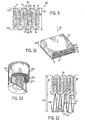
- synthetic or felted fiber media 24 is fed between rollers 26 and 28 and then between platens 30 and 32 which hold the material in place during downward movement of mandrel 34 having a plurality of lower downwardly extending needles 36 which punch through material 24, Fig. 3, to form the noted needle holes 22, Fig. 4, whereafter the needled sheet is fed through exit rollers 38 and 40.
- the needle holes present discontinuities in the filtering media because they are relatively large pores as compared to the bulk fiber matrix.
- the large pores offer a path of low resistance to fluid flow, such as air.
- contaminant particles such as dust
- the velocity through the larger needle holes 22 increases correspondingly, as in a venturi. Consequently, both uncaptured and detached reentrained contaminant particles can penetrate the filter through such needle holes 22, causing lower filter efficiency.
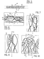
- Fig. 5 shows filter material 42 of non-woven fibrous filter media as known in the prior art, which may or may not be needled.
- the fibers 44 in the sheet run predominantly along or parallel to the sheet, i.e. horizontally left-right in the orientation of Fig. 5, and perpendicular to the direction of fluid flow as shown at arrow 46, Figs. 5 and 6.
- the surface area of the fibers available for adhesion and capture of contaminant particles 48 is perpendicular to fluid flow direction 46.
- Contaminant particles will aggregate on each other for example as shown at aggregate 50, and will also form particle bridges between fibers for example as shown at 52. Contaminant particle aggregates and bridges block flow and shorten filter life by leading to premature restriction and pressure drop.
- the larger pores provided by needle holes 22 offer the noted path of lower restriction and higher velocity, particularly due to faster clogging of smaller pores at adjacent areas between the needle holes, particularly at aggregates 50 and bridges 52. Consequently, as above noted, both uncaptured and detached reentrained contaminant particles can penetrate the filter through the needle holes.
- the contaminant particle aggregates and bridges in areas between needle holes are further subject to instability and reentrainment if exposed to high flow rates or pulsation, for example at the beginning of filter operation, such as at start-up of an internal combustion engine and the initial high air flow rate through the air filter therefor, and also due to the high velocity venturi effect of flow through needle holes 22 if the media is needled.
- the invention provides the possibility of filtering particles in a fluid flowing along flow direction 46, Fig. 7, through filter media 60 having a plurality of fibers 62.
- This increases capture of and retention of contaminant particles 64 by fibers 62 by increasing residence dwell time of particles moving along the fibers to increase the chance of, and extend the time of, fiber-particle contact, increasing Brownian diffusion probability of particles diffusing to the fibers, increasing the spread of, and even loading of, particles along the fibers, and reducing particle agglomeration and particle bridging between fibers which would otherwise block flow and be subject to instability and reentrainment if exposed to high flow rates or pulsation.
- the increased residence dwell time, increased Brownian diffusion, increased spread and evenness of particle loading, and reduced particle agglomeration and bridging, are all accomplished simply by orienting fibers 62 dominantly parallel to flow direction 46 in combination with providing fibers 62 of sufficient length along flow direction 46 such that residence dwell time is increased, Brownian diffusion is increased, spread and evenness of particle loading is increased, and particle agglomeration and bridging is reduced, all as compared to, and relative to, filter media fibers 44, Fig. 6, extending perpendicular to flow direction 46.
- filter media fibers 44, Fig. 6 extending perpendicular to flow direction 46.
- the perpendicular fiber orientation provides shorter particle-fiber contact time, less chance of diffusion, greater particle bridging, and uneven loading along the fiber length
- the parallel fiber orientation of Fig. 7 provides a greater chance of longer particle-fiber contact time, a greater chance of diffusion of a particle to a fiber, less particle bridging between fibers, and more even loading along the fiber length.
- Fig. 7 The parallel orientation of Fig. 7 enables the use of non-woven, nonneedled media, which is desirable.
- fibers 62 are the same, for example synthetic material such as polyester, and have the same diameter.
- at least first and second sets of different fibers are used. The latter alternative may include differing fiber diameters to enhance efficiency.
- a triboelectric fiber combination is used to provide a triboelectric effect. Triboelectric fibers are or may become (with usage) differentially charged, as is known.
- Fig. 8 shows filter media 66 having positively charged fibers 68, such as nylon, silk, cotton, cellulose, acrylic, polyethylene, polypropylene, modacrylic, and negatively charged fibers 70 such as chlorofiber.
- the oppositely charged fibers define a plurality of electric field flux lines therebetween, and in the desirable orientation of Fig. 8 such flux lines extend dominantly perpendicular to flow direction 46 and are stacked along such flow direction in a plane parallel thereto such that fluid flows along such plane and perpendicular to the flux lines and cuts serially sequentially across plural flux lines, increasing the chances of triboelectric capture due to the increased number of flux lines crossed, relative to known triboelectric capture techniques.
- Filter media construction is provided by a sheet 80 having a thickness dimension 82 between oppositely facing first and second sides 84 and 86 for filtering contaminant particles in fluid flow therethrough along flow direction 46 perpendicular to sheet 80 and first and second sides 84 and 86 and parallel to thickness dimension 82.
- Sheet 80 is formed by an internal pleated subsheet 88 comprising a plurality of fibers 90 and having a plurality of pleats 92, 94, etc. extending between first and second sets of pleat tips 96 and 98.
- Pleats 92, 94 extend parallel to flow direction 46.
- the first set of pleat tips 96 provides the first side 84 of sheet 80.
- the second set of pleat tips 98 provides the second side 86 of sheet 80.
- One or both sides 84 and 86 may additionally include a thin scrim layer or the like as shown at dashed lines 100 and 102.
- Pleats 92, 94, etc. engage each other and are packed against each other sufficiently tightly such that fluid flows along flow direction 46 through the pleats in parallel therewith, rather than between the pleats and then transversely therethrough as in standard pleated filter media designs.
- Subsheet 88 has a pre-pleated planar condition with fibers 90 extending dominantly parallel thereto and dominantly unidirectionally parallel to each other.
- Subsheet 88 has a pleated condition as shown in Figs. 9 and 10 forming macro sheet 80 wherein fibers 90 extend along pleats 92, 94, etc., substantially parallel to flow direction 46. Fibers 90 extend around pleat tips 96, 98 substantially parallel to each respective side 84, 86 of sheet 80 and substantially perpendicular to flow direction 46.
- pleats 92, 94, etc. are bonded to each other as shown at adhesive 104 to prevent flow of fluid therebetween along flow direction 46 parallel to pleats 92 and 94.
- the bonding of the pleats to each other enhances compression resistance of sheet 80 along thickness dimension 82 and eliminates the need for needle holes associated with needling.
- Sheet 80 may be used as a high capacity filter or as a prefilter to increase total filter efficiency and capacity.
- Figs. 11 and 12 show an embodiment of the latter which is an extended life two-stage fluid filter assembly 110 for filtering particles in fluid flow therethrough along flow direction 46.
- the assembly includes a first upstream prefilter element provided by sheet 80, and a second downstream main filter element 112.
- Filter element 112 is a pleated media (e.g., paper) filter element having a plurality of pleats 114, 116, etc. extending between first and second sets of pleat tips 118 and 120.
- the pleats of each of filter elements 80 and 112 are substantially parallel to flow direction 46 and extend along flow direction 46 between respective pleat tips.
- the pleats of filter element 112 are spaced from each other along a spacing direction 122 transverse to flow direction 46 and defining a transverse gap 124 therebetween through which fluid flows. Fluid flows transversely through pleats 114, 116 of filter element 112, as shown at arrows 126, 128. The pleats of filter element 80 are packed against each other, as above described, without such transverse gap and block fluid flow therebetween.
- upstream filter element 80 fluid flows along flow direction 46 through pleats 92, 94 in parallel therewith, rather than transversely therethrough. Fluid flow through pleats 114, 116 of downstream main filter element 112 is substantially transverse to flow direction 46. Fluid flow through pleats 92, 94 of upstream prefilter element 80 is substantially parallel to flow direction 46.
- each of main filter element 112 and prefilter element 80 are flat planar panels.
- each of main filter element 112a and prefilter element 80a are annular, and flow direction 46a is radial relative thereto.
- Prefilter element 80a is concentric to main filter element 112a.
- filter elements 80 and 112 may be conical or frustoconical, or other desired shapes. In each case, filter media construction 80 may be used alone or in combination with another filter element such as 112.
- the solidity of subsheet 88 be in the range of 1% to 10%
- the fiber size of fibers 90 be in the range of 0.1 to 50 denier
- the thickness dimension 82 of sheet 80 be in the range of 2 to 75 millimeters
- the ratio of velocity of fluid flow through prefilter element 80 to the velocity of fluid flow through main filter element 112 be in the range of 2 to 25.
- the invention enables use of a non-woven non-needled fibrous macro filter media sheet formed by a convoluted or pleated internal structure subsheet for fluid filtration, including gaseous or air filtration.
- a sheet 80 may be used as a high capacity filter or as a prefilter to increase total filter efficiency and capacity.
- the thickness 82 of the filter media is equivalent to the internal convolution or pleat depth.
- the media preferably retains its form by bonding at 104 the fibers on adjacent faces of the pleats 94, 92. This enhances the media's compression resistance and increases its rigidity such that no additional backing is required for the media to retain its shape, though additional outer scrim layers such as 100 and 102 may optionally be added if desired.
- the tight packing of the pleats and bonding at 104 is further desired to eliminate the need for needle holes associated with prior needling techniques, thereby eliminating needle holes 22, and improving filtration efficiency. If desired, bonding 104 may be deleted if pleats 92, 94 are sufficiently tightly packed.
- the tightly packed convoluted internal subsheet structure 88 causes the majority of fibers 90 to be oriented in a direction parallel to fluid flow 46, affording advantages of longer residence time for particles passing through the media, reduced particle agglomeration and bridging, higher collapse strength, increased capacity and efficiency.
- the fiber orientation and filter media construction is further desirable because it is conducive to the use of mixed fibers, including different diameter fibers and/or different polarity fibers, the latter being further desirable because it provides an enhanced triboelectric effect due to flux lines stacked along the flow direction such that fluid flows perpendicular to the flux lines and cuts serially sequentially across plural flux lines, increasing the chances of triboelectric capture due to the increased number of flux lines crossed.
- This enhanced triboelectric effect beyond traditional triboelectric mechanisms, is useful for capturing small particles which typically clog a downstream main or primary filter such as 112.
- the invention is particularly useful for increasing filter life in filters exposed to high dust concentrations of dry and/or sooty and/or oily particles.
- Previous non-woven designs used needling techniques to achieve the required media thickness and solidity.
- needle holes are formed through the media.
- Such needle holes formed in felted and other synthetic filter materials, promote the penetration of detached and reentrained particles.
- the needle holes present discontinuities in the filter media structure because they are relatively large pores when compared to the bulk fiber matrix. The large pores offer a path of low resistance to the fluid flow. Because the smaller pores in areas laterally between needle holes are clogged faster by deposited particles, the velocity through the larger needle holes increases correspondingly.
- the extended life two-stage filter assembly noted above may be provided in a variety of geometrical configurations, as noted, to achieve ultrahigh contaminant holding capacity and long life in high concentration areas, for instance in dusty construction areas and/or in oily and sooty environments.
- the main filter 112 is located downstream of the prefilter 80.
- the main filter is made of pleated filter media impregnated cellulose with a possible mixture of synthetic fibers such as polyester to secure shape stability when exposed to moisture, water and snow.
- the media of the pleated main filter element 1 12 can be treated with an oily substance to prevent clogging by sooty particles, as is known.
- the upstream prefilter 80 is made of non-woven nonneedled filter media of synthetic fibers of preferably differently charged materials to fully utilize the triboelectric effect, and to provide an enhanced triboelectric effect as noted.
- Another advantage of the disclosed filter media construction is that the contaminant cake remains stable due to the noted high rigidity and compression resistance.
- the compression resistance of the media at its low solidity enables formation of a uniformly distributed and stable contaminant cake which does not collapse when exposed to flow pulsation and vibration of the filtration system.
- the contaminant particles penetrating the prefilter are evenly distributed over the entire area of the pleated main filter element 112 located downstream of prefilter 80. Since pressure drop reaches its lowest value for uniformly distributed particles on the media surface, i.e. a uniformly thin contaminant cake, the contaminant capacity reaches its maximum value.
- the present invention provides a method of increasing contaminant cake stability on filter media fibers in filter media filtering contaminant particles by engaging and packing pleats 92 and 94 against each other, preferably by bonding at 104, to enhance rigidity and compression resistance of sheet 80 along thickness dimension 82.
- the invention further provides a method for evenly distributing fluid flow over the area of main filter element 112 after passage through prefilter element 80, by increasing uniformity of the contaminant cake on prefilter 80 by reducing particle agglomeration and particle bridging between prefilter media fibers which would otherwise block flow and reduce uniformity and be subject to instability and reentrainment, and instead orient prefilter filters 62, Fig. 7, 90, Fig. 9, dominantly parallel to flow direction 46 to more evenly load contaminant particles along the entire length of the fibers as compared to, and relative to, filter media fibers extending perpendicular to the flow direction.
- the dwell or residence time for the contaminant particles moving the vicinity of the fiber surface is extended. This enhances small particle, e.g. diesel soot, captured by the fibers because of diffusion and by triboelectric effect if differentially charged fibers are used, which effect is enhanced as above noted.
- the parallel fibers form channel-like paths in which viscous flow predominates. In the viscous flow, the boundary layer is slower and relatively thick, and hence more particles will have a chance to settle on the fiber surface due to Brownian diffusion and due to electrostatic mechanisms. The present method and orientation makes conditions favorable for these mechanisms to occur.
- the table below shows test results for filter assembly 1 10 of Fig. 1.
- the assembly had a length of 175 millimeters, a width of 175 millimeters, and a height or thickness 130 of 38 millimeters.
- the thickness 82 of prefilter 80 was 25 millimeters, and the thickness 132 of main filter 1 12 was 13 millimeters.
- the flow rate was 85m3/h (cubic meters per hour).
- Pa denotes pascals.
- kPa denotes kilopascals.
- g denotes grams.
- g/m2 denotes grams per square meter.
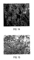
- the first three rows in the table note performance results for a needled perpendicular fiber media known in the prior art, Figs.
- Fig. 14 is a photomicrograph at 35 times enlargement showing the surface of the last noted prior art prefilter after testing. Of note are the craters visible at the needle holes, such as 22, Figs. 1 and 4, and the discontinuity and uneven contaminant cake loading across such surface.
- Fig. 15 is a photomicrograph at 35 times enlargement of the present prefilter element 80 noted in the fourth row of the table after the noted testing. Of note in Fig. 15 is the uniform evenly distributed contaminant cake loading.
Landscapes
- Chemical & Material Sciences (AREA)
- Chemical Kinetics & Catalysis (AREA)
- Engineering & Computer Science (AREA)
- Textile Engineering (AREA)
- Filtering Materials (AREA)
- Filtering Of Dispersed Particles In Gases (AREA)
- Electrostatic Separation (AREA)
Applications Claiming Priority (2)
| Application Number | Priority Date | Filing Date | Title |
|---|---|---|---|
| US526356 | 1990-05-21 | ||
| US09/526,356 US6387144B1 (en) | 2000-03-16 | 2000-03-16 | Enhanced performance fibrous filter media and extended life fluid filter assembly |
Publications (2)
| Publication Number | Publication Date |
|---|---|
| EP1136113A1 EP1136113A1 (en) | 2001-09-26 |
| EP1136113B1 true EP1136113B1 (en) | 2003-07-02 |
Family
ID=24097003
Family Applications (1)
| Application Number | Title | Priority Date | Filing Date |
|---|---|---|---|
| EP01105393A Expired - Lifetime EP1136113B1 (en) | 2000-03-16 | 2001-03-12 | Fibrous filter media |
Country Status (6)
| Country | Link |
|---|---|
| US (1) | US6387144B1 (enExample) |
| EP (1) | EP1136113B1 (enExample) |
| JP (1) | JP4614033B2 (enExample) |
| AU (1) | AU772279B2 (enExample) |
| BR (1) | BR0101074A (enExample) |
| DE (1) | DE60100409T2 (enExample) |
Families Citing this family (25)
| Publication number | Priority date | Publication date | Assignee | Title |
|---|---|---|---|---|
| KR100687111B1 (ko) * | 2003-06-10 | 2007-02-27 | 이비덴 가부시키가이샤 | 벌집형 구조체 |
| EP1541216B1 (en) * | 2003-07-15 | 2010-10-13 | Ibiden Co., Ltd. | Honeycomb structure body |
| US7097694B1 (en) | 2003-12-04 | 2006-08-29 | Fleetguard, Inc. | High performance, high efficiency filter |
| EP1547690B1 (en) * | 2003-12-12 | 2011-07-06 | Becton, Dickinson and Company | Membrane attachment process by hot melting without adhesive |
| JP5011133B2 (ja) * | 2005-03-04 | 2012-08-29 | ポール・コーポレーション | 波形流体処理ユニット及びその作製方法 |
| US7323106B2 (en) * | 2005-09-01 | 2008-01-29 | Fleetguard, Inc. | Multi-element filter with multiple pleat channel height |
| US7828869B1 (en) | 2005-09-20 | 2010-11-09 | Cummins Filtration Ip, Inc. | Space-effective filter element |
| US8114183B2 (en) | 2005-09-20 | 2012-02-14 | Cummins Filtration Ip Inc. | Space optimized coalescer |
| US7674425B2 (en) * | 2005-11-14 | 2010-03-09 | Fleetguard, Inc. | Variable coalescer |
| US7959714B2 (en) | 2007-11-15 | 2011-06-14 | Cummins Filtration Ip, Inc. | Authorized filter servicing and replacement |
| US20070062886A1 (en) | 2005-09-20 | 2007-03-22 | Rego Eric J | Reduced pressure drop coalescer |
| US8231752B2 (en) * | 2005-11-14 | 2012-07-31 | Cummins Filtration Ip Inc. | Method and apparatus for making filter element, including multi-characteristic filter element |
| DE102006014236A1 (de) | 2006-03-28 | 2007-10-04 | Irema-Filter Gmbh | Plissierbares Vliesmaterial und Verfahren und Vorrichtung zur Herstellung derselben |
| US8303693B2 (en) * | 2007-04-26 | 2012-11-06 | The Hong Kong Polytechnic University | Nanofiber filter facemasks and cabin filters |
| US8021466B2 (en) | 2008-03-18 | 2011-09-20 | Carpenter Co. | Fluid flow filter and method of making and using |
| USD643099S1 (en) | 2009-04-28 | 2011-08-09 | S.C. Johnson & Son, Inc. | Filter frame for a dust removal and prevention device |
| WO2011041539A1 (en) * | 2009-09-30 | 2011-04-07 | Cummins Filtration Ip Inc. | Auxiliary o-ring gland |
| DE102010052155A1 (de) | 2010-11-22 | 2012-05-24 | Irema-Filter Gmbh | Luftfiltermedium mit zwei Wirkmechanismen |
| WO2013088260A1 (en) | 2011-12-16 | 2013-06-20 | Helen Of Troy Limited | Gravity filter |
| DE102013008402B4 (de) | 2013-05-16 | 2025-07-17 | Irema-Filter Gmbh | Faservlies und Verfahren zur Herstellung desselben |
| DE102014117506A1 (de) | 2014-11-28 | 2016-06-02 | Filta Co., Ltd | Filtermedium mit großem Faltenabstand |
| EP3331631B1 (en) | 2015-08-03 | 2019-10-09 | Parker-Hannificn Corporation | Filter with preferential air flow |
| KR102060089B1 (ko) * | 2017-09-05 | 2020-02-12 | 경기대학교 산학협력단 | 미세 먼지 포집 장치 |
| CN107617231A (zh) * | 2017-09-22 | 2018-01-23 | 刘超 | 一种凝聚分离装置 |
| CN115531978B (zh) * | 2022-09-14 | 2024-07-19 | 江苏永冠给排水设备有限公司 | 一种用于饮用水处理的新型悬浮轻质滤料的制备方法及应用 |
Family Cites Families (46)
| Publication number | Priority date | Publication date | Assignee | Title |
|---|---|---|---|---|
| US2688380A (en) | 1951-07-13 | 1954-09-07 | American Viscose Corp | Filter cartridge |
| US3192598A (en) * | 1961-01-03 | 1965-07-06 | Novo Ind Corp | Method of making a filter element |
| US3258900A (en) | 1963-08-06 | 1966-07-05 | American Air Filter Co | Unit filter assembly |
| US3920428A (en) | 1974-03-25 | 1975-11-18 | Ethyl Corp | Filter element |
| US3877909A (en) | 1974-04-23 | 1975-04-15 | Drico Ind Corp | Internally self-supporting filter and process for making same |
| US4181513A (en) | 1974-11-05 | 1980-01-01 | Toyobo Co., Ltd. | Carbon adsorptive filter material with layers of reinforcing non woven fabrics needle punched |
| GB1603519A (en) * | 1978-01-23 | 1981-11-25 | Process Scient Innovations | Filter elements for gas or liquid and methods of making such filters |
| US4154688A (en) | 1978-01-27 | 1979-05-15 | Pall Corporation | Collapse-resistant corrugated filter element |
| CA1127494A (en) | 1979-11-21 | 1982-07-13 | American Filtrona Corporation | Filter manufacturing technique |
| DE3003409C2 (de) | 1980-01-31 | 1985-01-10 | Schulz & Co, 5830 Schwelm | Filterelement zur Luft- und Gasreinigung |
| US4369117A (en) | 1980-05-12 | 1983-01-18 | American Hospital Supply Corporation | Serum separating method and apparatus |
| CH647935A5 (fr) | 1980-08-04 | 1985-02-28 | Molins Ltd | Procede pour la production d'un materiau de remplissage, machine pour sa mise en oeuvre, application du procede et installation pour la production d'un boudin de filtres de cigarettes. |
| US4915835A (en) * | 1983-03-21 | 1990-04-10 | Filtration Water Filters For Agri. And Indt. Ltd. | Flushable fiber-filter element for filtering a fluid |
| EP0154845A3 (de) | 1984-02-24 | 1986-06-18 | Sartorius GmbH. | Flaches Filterelement zur Filtration von Fluiden |
| DE3414578A1 (de) | 1984-04-17 | 1985-10-24 | Bert 5470 Andernach Steffens | Faserstrang-filterkoerper |
| GB8623909D0 (en) | 1986-10-06 | 1986-11-12 | British Railways Board | Air filters |
| US4765812A (en) | 1987-10-30 | 1988-08-23 | Allied-Signal Inc. | Air laid filtering material |
| JPH0722662B2 (ja) * | 1988-08-09 | 1995-03-15 | チッソ株式会社 | フィルター |
| US4840838A (en) * | 1988-09-08 | 1989-06-20 | E. I. Du Pont De Nemours And Company | High temperature filter felt |
| DE8901213U1 (de) | 1989-02-03 | 1989-04-06 | Parabeam B.V., Helmond | Filter |
| JP2949789B2 (ja) * | 1990-06-08 | 1999-09-20 | 東レ株式会社 | フィルターユニット |
| EP0465424B1 (de) * | 1990-07-05 | 1994-12-07 | Filtrox-Werk AG | Tiefbettfilter, Verfahren zur Herstellung einer Filterschicht und Filtermodul |
| JPH05263345A (ja) * | 1991-09-12 | 1993-10-12 | Nippon Felt Kogyo Kk | 繊維層材及びその製造方法 |
| EP0543147B1 (en) * | 1991-10-18 | 1997-06-25 | PETOCA Ltd. | Carbon fiber felt and process for its production |
| JP2719848B2 (ja) * | 1992-01-31 | 1998-02-25 | 株式会社大貴 | 動物の排泄物処理材及びその製造方法 |
| CH681510A5 (enExample) | 1992-02-10 | 1993-04-15 | Leyat Fils Marketing Sa | |
| DK136192D0 (da) | 1992-11-09 | 1992-11-09 | John Reipur | Filter |
| US5605748A (en) | 1993-01-22 | 1997-02-25 | Monsanto Enviro-Chem Systems, Inc. | Fiber beds for fiber bed mist eliminators |
| US5429864A (en) * | 1993-10-06 | 1995-07-04 | E. I. Du Pont De Nemours And Company | High efficiency filter fabric for hot gas filtration |
| DE4336595C2 (de) | 1993-10-27 | 2001-11-08 | Saechsisches Textilforsch Inst | Mehrschichtiger, voluminöser Filterstoff |
| DE9414040U1 (de) | 1994-08-30 | 1995-01-19 | Hoechst Ag, 65929 Frankfurt | Vliese aus Elektretfasermischungen mit verbesserter Ladungsstabilität |
| AU685995B2 (en) * | 1994-09-09 | 1998-01-29 | Kimberly-Clark Worldwide, Inc. | Z-direction liquid transport medium |
| IL111162A (en) | 1994-10-04 | 1998-01-04 | Irad Technologies Ltd | Filtering device utilizable with gas monitors |
| JPH08290026A (ja) * | 1995-04-20 | 1996-11-05 | Nippon Felt Kogyo Kk | エアーフィルター材及びその製造方法 |
| DE19541252C1 (de) * | 1995-11-06 | 1996-12-19 | Techtex Gmbh Mittweida | Mehrschichtiges, voluminöses Filtermedium mit speichernder Wirkung |
| FR2742069B1 (fr) | 1995-12-08 | 1998-02-27 | Kerplas Snc | Cartouche filtrante, son procede de fabrication, son application a un embout de flacon, et procede de fabrication d'un embout de flacon |
| US5702603A (en) | 1996-03-22 | 1997-12-30 | Johnson; Todd W. | Self-sealing liquid filter |
| US5667544A (en) | 1996-04-29 | 1997-09-16 | Aaf International | Extended life filter apparatus |
| US5898981A (en) * | 1996-04-30 | 1999-05-04 | Minnesota Mining & Manufacturing Company | Synthetic filter media and method for manufacturing same |
| US6211100B1 (en) * | 1996-04-30 | 2001-04-03 | Minnesota Mining And Manufacturing Company | Synthetic filter media |
| US5928414A (en) * | 1996-07-11 | 1999-07-27 | W. L. Gore & Associates, Inc. | Cleanable filter media and filter elements |
| US6056809A (en) * | 1996-10-18 | 2000-05-02 | Rick L. Chapman | High efficiency permanent air filter and method of manufacture |
| US5785725A (en) | 1997-04-14 | 1998-07-28 | Johns Manville International, Inc. | Polymeric fiber and glass fiber composite filter media |
| JPH11188216A (ja) * | 1997-12-25 | 1999-07-13 | Dynic Corp | フィルターと濾過装置 |
| DE19821869A1 (de) | 1998-05-15 | 1999-11-18 | Wolfgang Mertner Inh Ing Kurt | Filtereinrichtung zum Entfernen von Ruß aus rußhaltigen Gasen, insbesondere aus Abgasen von Diesel-Brennkraftmaschinen |
| US6165244A (en) * | 1999-03-13 | 2000-12-26 | Aaf International, Inc. | Filter media with fluid stream positioned fibers |
-
2000
- 2000-03-16 US US09/526,356 patent/US6387144B1/en not_active Expired - Lifetime
-
2001
- 2001-02-02 AU AU18247/01A patent/AU772279B2/en not_active Ceased
- 2001-03-12 DE DE60100409T patent/DE60100409T2/de not_active Expired - Lifetime
- 2001-03-12 EP EP01105393A patent/EP1136113B1/en not_active Expired - Lifetime
- 2001-03-14 JP JP2001072745A patent/JP4614033B2/ja not_active Expired - Fee Related
- 2001-03-15 BR BR0101074-3A patent/BR0101074A/pt not_active Application Discontinuation
Also Published As
| Publication number | Publication date |
|---|---|
| AU1824701A (en) | 2001-09-20 |
| BR0101074A (pt) | 2001-11-06 |
| US6387144B1 (en) | 2002-05-14 |
| EP1136113A1 (en) | 2001-09-26 |
| AU772279B2 (en) | 2004-04-22 |
| JP4614033B2 (ja) | 2011-01-19 |
| JP2001286713A (ja) | 2001-10-16 |
| DE60100409D1 (de) | 2003-08-07 |
| DE60100409T2 (de) | 2004-01-08 |
Similar Documents
| Publication | Publication Date | Title |
|---|---|---|
| EP1136113B1 (en) | Fibrous filter media | |
| US7097694B1 (en) | High performance, high efficiency filter | |
| EP1276548B1 (en) | Filter media | |
| US5496627A (en) | Composite fibrous filters | |
| US4976858A (en) | Multi-layer filter medium | |
| US4765812A (en) | Air laid filtering material | |
| US20220152527A1 (en) | Perforated layer coalescer | |
| JPH09503958A (ja) | 流体フィルタ | |
| US12290772B2 (en) | Composite filter media with multiple fiber structures including nanofibers | |
| WO2007126539A1 (en) | High capacity filter medium | |
| JP2003340220A (ja) | フィルター用不織布及びエンジン用フィルター | |
| JP2007046478A (ja) | 内燃機関エアクリーナ用濾材およびエアクリーナエレメント | |
| CN106955528A (zh) | 无纺布滤材和空气滤清器滤芯 | |
| US5714067A (en) | High efficiency and high capacity filter media | |
| WO1993012862A1 (en) | Filter element for filtering fluids | |
| EP0980700B2 (en) | Filter medium having improved filtration and strength characteristics | |
| RU2075330C1 (ru) | Многослойный фильтровальный материал | |
| KR102016342B1 (ko) | 연료 펌프용 필터 구조체 | |
| RU2006653C1 (ru) | Фильтрующий элемент воздухоочистителя двигателя внутреннего сгорания | |
| JP2557454Y2 (ja) | 空調用粗塵フィルタ | |
| JP3677367B2 (ja) | 筒状フィルタ | |
| KR100352506B1 (ko) | 공기청정용 필터 여재 및 그 제조방법 | |
| JPH1085526A (ja) | プレフィルタ | |
| JPS5923847B2 (ja) | 空気清浄器用「ろ」材 | |
| HK1084351B (en) | High efficiency ashrae filter media |
Legal Events
| Date | Code | Title | Description |
|---|---|---|---|
| PUAI | Public reference made under article 153(3) epc to a published international application that has entered the european phase |
Free format text: ORIGINAL CODE: 0009012 |
|
| AK | Designated contracting states |
Kind code of ref document: A1 Designated state(s): AT BE CH CY DE DK ES FI FR GB GR IE IT LI LU MC NL PT SE TR Kind code of ref document: A1 Designated state(s): DE FR GB |
|
| AX | Request for extension of the european patent |
Free format text: AL;LT;LV;MK;RO;SI |
|
| RAP1 | Party data changed (applicant data changed or rights of an application transferred) |
Owner name: NELSON INDUSTRIES, INC. |
|
| 17P | Request for examination filed |
Effective date: 20020316 |
|
| AKX | Designation fees paid |
Free format text: AT BE CH LI |
|
| RBV | Designated contracting states (corrected) |
Designated state(s): DE FR GB |
|
| REG | Reference to a national code |
Ref country code: DE Ref legal event code: 8566 |
|
| 17Q | First examination report despatched |
Effective date: 20020701 |
|
| GRAH | Despatch of communication of intention to grant a patent |
Free format text: ORIGINAL CODE: EPIDOS IGRA |
|
| RAP1 | Party data changed (applicant data changed or rights of an application transferred) |
Owner name: FLEETGUARD, INC. |
|
| RTI1 | Title (correction) |
Free format text: FIBROUS FILTER MEDIA |
|
| GRAH | Despatch of communication of intention to grant a patent |
Free format text: ORIGINAL CODE: EPIDOS IGRA |
|
| GRAA | (expected) grant |
Free format text: ORIGINAL CODE: 0009210 |
|
| AK | Designated contracting states |
Designated state(s): DE FR GB |
|
| PG25 | Lapsed in a contracting state [announced via postgrant information from national office to epo] |
Ref country code: FR Free format text: LAPSE BECAUSE OF FAILURE TO SUBMIT A TRANSLATION OF THE DESCRIPTION OR TO PAY THE FEE WITHIN THE PRESCRIBED TIME-LIMIT Effective date: 20030702 |
|
| REG | Reference to a national code |
Ref country code: GB Ref legal event code: FG4D |
|
| REF | Corresponds to: |
Ref document number: 60100409 Country of ref document: DE Date of ref document: 20030807 Kind code of ref document: P |
|
| PLBE | No opposition filed within time limit |
Free format text: ORIGINAL CODE: 0009261 |
|
| STAA | Information on the status of an ep patent application or granted ep patent |
Free format text: STATUS: NO OPPOSITION FILED WITHIN TIME LIMIT |
|
| 26N | No opposition filed |
Effective date: 20040405 |
|
| EN | Fr: translation not filed | ||
| PG25 | Lapsed in a contracting state [announced via postgrant information from national office to epo] |
Ref country code: GB Free format text: LAPSE BECAUSE OF NON-PAYMENT OF DUE FEES Effective date: 20050312 |
|
| GBPC | Gb: european patent ceased through non-payment of renewal fee |
Effective date: 20050312 |
|
| REG | Reference to a national code |
Ref country code: DE Ref legal event code: R082 Ref document number: 60100409 Country of ref document: DE Representative=s name: VON ROHR PATENTANWAELTE PARTNERSCHAFT MBB, DE |
|
| PGFP | Annual fee paid to national office [announced via postgrant information from national office to epo] |
Ref country code: DE Payment date: 20140327 Year of fee payment: 14 |
|
| REG | Reference to a national code |
Ref country code: DE Ref legal event code: R119 Ref document number: 60100409 Country of ref document: DE |
|
| PG25 | Lapsed in a contracting state [announced via postgrant information from national office to epo] |
Ref country code: DE Free format text: LAPSE BECAUSE OF NON-PAYMENT OF DUE FEES Effective date: 20151001 |
|
| REG | Reference to a national code |
Ref country code: DE Ref legal event code: R082 Ref document number: 60100409 Country of ref document: DE Representative=s name: PROCK, THOMAS, DR., GB |