EP1134591A1 - System zur Messung eines Radiofrequenzsignals in einer drahtlosen Station und ein Leiterplatteschalter - Google Patents
System zur Messung eines Radiofrequenzsignals in einer drahtlosen Station und ein Leiterplatteschalter Download PDFInfo
- Publication number
- EP1134591A1 EP1134591A1 EP01660048A EP01660048A EP1134591A1 EP 1134591 A1 EP1134591 A1 EP 1134591A1 EP 01660048 A EP01660048 A EP 01660048A EP 01660048 A EP01660048 A EP 01660048A EP 1134591 A1 EP1134591 A1 EP 1134591A1
- Authority
- EP
- European Patent Office
- Prior art keywords
- testing
- wireless station
- measuring head
- card
- switching means
- Prior art date
- Legal status (The legal status is an assumption and is not a legal conclusion. Google has not performed a legal analysis and makes no representation as to the accuracy of the status listed.)
- Granted
Links
- 238000012360 testing method Methods 0.000 claims abstract description 239
- 238000000034 method Methods 0.000 claims abstract description 23
- 238000005259 measurement Methods 0.000 claims description 40
- 230000008878 coupling Effects 0.000 claims description 14
- 238000010168 coupling process Methods 0.000 claims description 14
- 238000005859 coupling reaction Methods 0.000 claims description 14
- 239000000523 sample Substances 0.000 claims description 7
- 230000035945 sensitivity Effects 0.000 claims description 4
- 238000001228 spectrum Methods 0.000 claims description 4
- 230000000694 effects Effects 0.000 claims description 3
- 230000008901 benefit Effects 0.000 description 3
- 238000010586 diagram Methods 0.000 description 2
- 229910052751 metal Inorganic materials 0.000 description 2
- 239000002184 metal Substances 0.000 description 2
- 150000002739 metals Chemical class 0.000 description 2
- 238000005476 soldering Methods 0.000 description 2
- PEZNEXFPRSOYPL-UHFFFAOYSA-N (bis(trifluoroacetoxy)iodo)benzene Chemical compound FC(F)(F)C(=O)OI(OC(=O)C(F)(F)F)C1=CC=CC=C1 PEZNEXFPRSOYPL-UHFFFAOYSA-N 0.000 description 1
- 238000006243 chemical reaction Methods 0.000 description 1
- 239000004020 conductor Substances 0.000 description 1
- 238000011161 development Methods 0.000 description 1
- 238000000691 measurement method Methods 0.000 description 1
- 238000012545 processing Methods 0.000 description 1
- 230000001681 protective effect Effects 0.000 description 1
- 229910000679 solder Inorganic materials 0.000 description 1
- 125000006850 spacer group Chemical group 0.000 description 1
Images


Classifications
-
- G—PHYSICS
- G01—MEASURING; TESTING
- G01R—MEASURING ELECTRIC VARIABLES; MEASURING MAGNETIC VARIABLES
- G01R31/00—Arrangements for testing electric properties; Arrangements for locating electric faults; Arrangements for electrical testing characterised by what is being tested not provided for elsewhere
- G01R31/28—Testing of electronic circuits, e.g. by signal tracer
- G01R31/282—Testing of electronic circuits specially adapted for particular applications not provided for elsewhere
- G01R31/2822—Testing of electronic circuits specially adapted for particular applications not provided for elsewhere of microwave or radiofrequency circuits
-
- G—PHYSICS
- G01—MEASURING; TESTING
- G01R—MEASURING ELECTRIC VARIABLES; MEASURING MAGNETIC VARIABLES
- G01R1/00—Details of instruments or arrangements of the types included in groups G01R5/00 - G01R13/00 and G01R31/00
- G01R1/02—General constructional details
- G01R1/06—Measuring leads; Measuring probes
- G01R1/067—Measuring probes
- G01R1/06772—High frequency probes
Definitions
- the present invention relates to a wireless system according to the preamble of Claim 1.
- the invention also relates to a method according to the preamble of Claim 11.
- the radio frequency power of a transmitter can be measured, for example, by coupling to the output of the transmitter a device, a test load, which converts essentially all the power fed by the transmitter to the output into heat, whereupon the power can be calculated from the temperature change.
- a generally used method is to use a thermocouple, which comprises two pieces of different metals joined together, in which the temperature causes a small voltage (so-called thermo voltage) to be created in the joint between the metals. This voltage, which is created in the joint, is very accurately proportional to the temperature of the joint.
- thermo voltage small voltage
- This voltage which is created in the joint, is very accurately proportional to the temperature of the joint.
- this method has the problem that it is very slow and expensive, especially with high frequencies. Measurement methods based on temperature are the most accurate of the prior art methods for determining the radio frequency power, but the problems of these methods are unreasonable with regard to the benefit gained from them.
- a general solution, by which the use of methods based on temperature can be avoided, is the measurement of power by means of a diode. Then the output of the wireless station is indicated in a diode and the indicated voltage is amplified, whereupon the radio frequency power can be calculated.
- the connector and the test load may have the effect that the diode creates only randomly a voltage which is proportional to the power. This is due to the fact that the diode only indicates the voltage of the output of the transmitter, from which the power is obtained by assuming that the current of the transmitter is proportional to the voltage. This is the case only when the resistive load coupled to the output of the transmitter is essentially as high as the self-impedance of the output of the transmitter
- the transmitters of wireless stations have been tuned, tested and serviced in service facilities by using an external antenna connector or by replacing the antenna with a separate measurement connector, which forms a galvanic coupling between the wireless station and the testing equipment.
- Wireless stations with a built-in antenna do not usually have such an external antenna connector.
- a less accurate RF (Radio Frequency) connector must be used, whereby the radio frequency power or other property to be measured, such as power, frequency, sensitivity, bit error rate or modulation spectrum, is measured from the wiring board of the wireless station, although the wireless station's own antenna has not been disconnected.
- these measurements of a radio frequency signal should be carried out very accurately and without the need to solder extra coaxial cables on the wiring board or to use an inaccurate RF connector.
- the wiring board can also include a test switch, which has preferably two different positions.
- this test switch When this test switch is in the operating position, the radio frequency signal proceeds from the wiring board of the wireless station to the wireless station's own antenna.
- this test switch When radio frequency power should be measured from the wireless station, this test switch is switched to the testing position with a measuring head, whereupon the wireless station's own antenna is disconnected to improve measurement accuracy. Then the radio frequency signal proceeds from the transmitter of the wireless station via the switch and the measuring head to the testing equipment.
- this switch is in the operating position, the radio frequency signal proceeds via the test switch to the wireless station's own antenna. This method provides much more accurate results than a method in which the antenna is not disconnected.
- test switch described above has the drawback that this test switch should be located outside the RF shield used in the radio frequency parts of the wireless station, and the measurement should be carried out from the side of the wiring board where the test switch is. In practice, this means that the wireless station should be dismantled for the duration of the measurement.
- the wiring boards of wireless stations are one-sided by soldering components on one side of the wiring board only.
- the wiring boards as such can consist of several layers of wiring.
- the antenna is located on the other side of the wiring board than the components that are soldered on the wiring board. If the wireless station meets both the conditions mentioned above, soldering the test switch described above on the same side of the wiring board with the wireless station's own antenna is not possible. Then the wireless station must be opened for servicing, for example, to enable the radio frequency power to be measured.
- a second purpose of the invention is to provide a system by which the measurement can be carried out quickly and easily, preferably without dismantling the wireless station.
- This first purpose can be achieved by forming a test switch on the wiring board of the wireless station, with a hole beneath the test switch in the wiring board. Through this hole, the test switch can be switched to the measuring position preferably with the measuring head, whereupon the wireless station's own antenna is disconnected to improve the accuracy of measurement. Then the radio frequency signal proceeds from the transmitter of the wireless station via the test switch and the measuring head to the testing equipment or to the opposite direction. When this switch is in the operating position, the radio frequency signal proceeds via the test switch to the wireless station's own antenna.
- the second purpose can be achieved by forming a testing hole, which is suitable for measuring the radio frequency power, also in the shell of the wireless station at the location of the test switch or in its vicinity.
- the system according to the invention is characterized in what is set forth in the characterizing part of Claim 1.
- the method according to the invention is characterized in what is set forth in the characterizing part of Claim 11.
- the present invention provides considerable advantages over the prior art methods.
- the wireless station's own antenna can be disconnected for the duration of the measurement of the radio frequency signal, the measuring accuracy is considerably improved.
- the test switch can be switched to the testing position from the other side of the wiring board of the wireless station than the one where this test switch is located, the test switch can be placed in a space protected with an RF shield. Then it is also much easier to place the components on one side of the wiring board of the wireless station only.
- a testing hole has been formed on the shell of the wireless station, it is not necessary to dismantle the wireless station for measuring the radio frequency power.
- the time needed for the measurement is substantially shorter, the measurement is very easy to carry out and the danger of sensitive parts in the wireless station being broken is much smaller than when using prior art solutions.
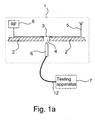
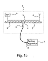
- FIGs 1a and 1b show a system according to the invention as a simplified drawing.
- This system preferably comprises at least a wireless station 1, a measuring head 6 and a testing apparatus 7.
- This testing apparatus preferably comprises at least means for measuring radio frequency power and means for feeding a radio frequency test signal.
- the wireless station preferably comprises at least a wiring board 2, switching means such as a test switch 3, an antenna 5 and a radio part 8.
- This test switch which has two different positions, has been installed on the wiring board of the wireless station. When this test switch is in the first position, i.e. in the operating position, or closed (Fig. 1a), the radio frequency signal proceeds from the radio part 8 via the test switch 3 to the wireless station's own antenna 5.
- this test switch 3 When radio frequency power should be measured from the wireless station 1, this test switch 3 is switched to the second position, i . e . to the test position or open (Fig. 1b) preferably with the measuring head 6.
- a switching aperture 4 such as a hole or a corresponding opening, slot or the like through the wiring board, through which the test switch can be opened with the measuring head from a different side of the wiring board than where the test switch has been installed. Then the test switch can be sufficiently well protected from external interference. In addition, it also becomes much easier to place the components on one side of the wiring board of the wireless station only.
- the wireless station's own antenna 5 is disconnected to improve the accuracy of measurement. Then the radio frequency signal proceeds from the radio part 8 of the wireless station via the measuring head and cable 12 to the testing apparatus 7.
- test switch 3 is switched to the testing position through the switching aperture 4, but it is not done with the measuring head 6.
- the arrangement is preferably such that a testing connector (not shown) for the measuring head has been formed on the surface of the wireless station 1.
- the testing connector has been coupled to the test switch so that when the test switch is in the testing position, the measurement can be carried out through the testing connector.
- This testing connector can be located, for example, beside the bottom connector and charging connector of the wireless station on the bottom of the wireless station.
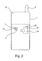
- a testing aperture 17 is preferably formed in the shell of the wireless station, conveniently so that it is essentially at the location of the switching aperture 4 formed in the wiring board 2. Through this testing aperture, the test switch 3 can be switched to the testing position and the testing apparatus can be coupled to the output of the radio part 8 of the wireless station.
- testing aperture need not necessarily be located exactly at the hole formed in the wiring board, as long as it is possible to switch the test switch to the testing position (open) through the testing aperture and to the operating position (closed) and to couple the testing apparatus to the output of the radio part.
- the testing aperture has preferably been formed so that it is not visible when the wireless station is used. A place like this is, for instance, under the battery (not shown) of the wireless station, where it is protected from foreign, external objects and dirt. It is also possible that the testing aperture is not under the battery, in which case the testing aperture is preferably covered (not shown) with a protective sticker or rubber bung.
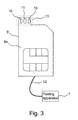
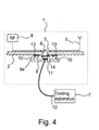
- testing card 9 One way of coupling the testing apparatus 7 to the output of the radio part 8 of the wireless station to advantage is to carry out the coupling by means of a separate testing card 9 (Fig. 3).
- This testing card is preferably installed in the place of the SIM card (Subscriber Identification Module) 18 of the wireless station for the duration of the measurement.
- SIM card Subscriber Identification Module
- this testing card differs from an ordinary SIM card in that it has a projecting part 15, on which there are provided on the lower surface 9a of the testing card, the surface which is placed against the wiring board 2 of the wireless station, grounding means 10, such as springs, and a measuring connection 11.
- the testing card is coupled to the testing apparatus 7 by means of a cable 12.
- the testing card can also contain all the properties of an ordinary SIM card to enable the wireless station to be used during the measurement of the radio frequency power.
- the testing card can contain, for example, a microprocessor and memory for saving the PIN code (Personal Identification Number), for example.
- the above mentioned testing aperture 17 is an extension 20 of the SIM card slot, and thus the test switch 3 and the hole 4 formed in the wiring board 2 are located essentially at the extension of the SIM card slot 19.
- the test switch 3 is on a different side of the wiring board than the testing card.
- the shape of the testing card also prevents it from being installed incorrectly in the SIM card slot.
- the testing card pushes the measuring head 6 upwards, whereupon the measuring head keeps the test switch 3 in the testing position.
- the measuring head has been placed as fixed in the wireless station, and thus the measuring head is coupled to the testing apparatus by means of the testing card.
- An ordinary SIM card 18 does not switch the test switch to the testing position, because it does not have a projecting part corresponding to the projecting part 15 of the testing card, which would open the test switch.
- the grounding means on the testing card are at least partly at the location of one or more grounding connections 13 on the wiring board of the wireless station.
- the measuring head touches the measuring connection 11 of the testing card and the test switch, whereupon the radio frequency signal proceeds from the radio part 8 via the switch 3, measuring head 6, measuring surface 11, testing card 9 and the cable 12 to the testing apparatus 7.
- the measuring head is returned to the lower position by means of a return spring 14, for example, whereupon the test switch is closed, i.e. returns to the operating position.
- the radio frequency signal proceeds again from the radio part via the switch to the wireless station's own antenna 5.
- testing card 9 does not have the projecting part 15 mentioned above. Then the appearance of this testing card differs from an ordinary SIM card in that there are provided on the lower surface 9a of the testing card, i.e. the surface that is placed against the wiring board 2 of the wireless station, grounding means 10, such as springs, and a measuring head 6.
- the testing card is coupled to the testing apparatus 7 by means of a cable 12. Even in this case, the testing card can also contain all the properties of an ordinary SIM card to enable the wireless station to be used during the measurement of the radio frequency power.
- the above mentioned testing aperture 17 is in the SIM card slot 19, and thus the test switch 3 and the hole 4 formed in the wiring board 2 are located essentially at this testing aperture.
- testing switch 3 is on a different side of the wiring board than the testing card.
- the measuring head 6 in the testing card keeps the test switch 3 in the testing position.
- An ordinary SIM card 18 does not switch the test switch to the testing position, because it does not have the measuring head 6 of the testing card, which would open the test switch.
- the grounding means on the testing card are at least partly at the location of one or more grounding connections 13 on the wiring board of the wireless station.
- the radio frequency signal proceeds from the radio part 8 via the switch 3, measuring head 6, testing card 9 and cable 12 to the measuring apparatus 7.
- the test switch is closed, i.e. returns to the operating position.
- the radio frequency signal proceeds again from the radio part via the switch to the wireless station's own antenna 5.
- the radio frequency power can also be measured by some other means than a testing card 9 installed in the SIM card slot 19.
- a testing card 9 installed in the SIM card slot 19.
- the essential feature of this method is the fact that the switching of the test switch to the testing position takes place on a different side of the wiring board 2 of the wireless station than where the test switch 3 is located. In addition, it is essential that the measurement is carried out without removing the shell 16 of the wireless station.
- FIG. 7 shows a system according to still another embodiment of the invention as a simplified drawing.
- the antenna is e.g. a so called PIFA type, wherein it comprises an antenna plate 25 and a spacer plate 24.
- RF power is connected to the antenna 5 by means of a power feeding pin 21.
- This power feeding pin 21 also comprises a first housing 22 and first loading means, e.g. a first spring 23, which ensures a good contact between the power feeding pin and the output of the radio part 8 of the wireless station.
- the first housing 22 is arranged to be movable substantially vertically. When the wireless station is in normal use, the first housing is 22 in contact with the antenna plate 25 and the power feeding pin 21 is in contact with the output of the radio part 8.
- the first housing 22 is made of electrically conducting material, wherein the radio frequency signal from the radio part 8 is coupled to the antenna plate 25.
- the testing probe 6 is situated on the hole 4 and pushed downwards, wherein the testing probe 6 pushes the first housing 22 downwards and disconnects the first housing 22 from the antenna plate 25.
- the radio frequency signal from the radio part 8 is now connected to the testing probe 6 instead of the antenna plate 25.
- the testing probe further comprises grounding means 10, which advantageously comprise a second housing 26, grounding pin 27 and second loading means, e.g. a second spring 28.
- the grounding means 10 are arranged with the testing probe 6 for providing a proper grounding connection for the testing apparatus while the testing probe 6 is connected to the first housing 22.
- the antenna plate 25 comprises an opening 30 through which the grounding pin 27 is able to make contact with the ground plane 29 e.g. at grounding connection 13.
- the invention was applied to a transmitter of the radio part 8, but it is naturally clear that the invention can be applied to a receiver as well. Tuning and measurement operations are also carried out for receivers, in which case measuring accuracy is an important consideration.
- a certain test signal is then fed to the radio part 8 from a testing apparatus 7, whereupon the required measurements can be carried out from the receiver.
- the test switch 3 is also switched to the testing position, in which the radio frequency test signal being fed does not proceed to the antenna. This switching is preferably carried out with another measuring head (not shown), whereupon the radio frequency test signal proceeds from the testing apparatus 7 via the cable 12 and the test switch 3 to the receiver of the radio part.
- the measurement is preferably carried out through a testing connector (not shown) provided on the surface of the wireless station, on which the measuring head 6 can be fitted, whereby the wireless station need not be dismantled for the duration of the measurement.
- the testing connector has been coupled to the test switch so that when the test switch is in the testing position and a certain radio frequency test signal is being fed from the testing apparatus, the measurement can be carried out through the testing connector.
- the first or second one switches the test switch to the testing position directly or indirectly, when the testing card is inserted into the wireless station for carrying out the measurement. Then a certain radio frequency test signal is fed to the receiver through the first measuring head, and the measurement is carried out through the second measuring head.
- the invention was described above with reference to the measurement of power, it is obvious that in addition to the measurement of radio frequency power, the invention can also be used for the measurement of other properties of a radio frequency signal.
- the property to be measured can be frequency, sensitivity, bit error rate or modulation spectrum, for example.
Landscapes
- Physics & Mathematics (AREA)
- General Physics & Mathematics (AREA)
- Engineering & Computer Science (AREA)
- General Engineering & Computer Science (AREA)
- Testing Electric Properties And Detecting Electric Faults (AREA)
- Monitoring And Testing Of Transmission In General (AREA)
- Mobile Radio Communication Systems (AREA)
- Transceivers (AREA)
Applications Claiming Priority (2)
| Application Number | Priority Date | Filing Date | Title |
|---|---|---|---|
| FI20000594A FI107841B (fi) | 2000-03-15 | 2000-03-15 | Järjestelmä radiotaajuisen signaalin mittaamiseksi langattomassa viestimessä |
| FI20000594 | 2000-03-15 |
Publications (2)
| Publication Number | Publication Date |
|---|---|
| EP1134591A1 true EP1134591A1 (de) | 2001-09-19 |
| EP1134591B1 EP1134591B1 (de) | 2009-07-22 |
Family
ID=8557929
Family Applications (1)
| Application Number | Title | Priority Date | Filing Date |
|---|---|---|---|
| EP01660048A Expired - Lifetime EP1134591B1 (de) | 2000-03-15 | 2001-03-14 | System zur Messung eines Radiofrequenzsignals in einer drahtlosen Station und ein Leiterplatteschalter |
Country Status (5)
| Country | Link |
|---|---|
| US (1) | US7020443B2 (de) |
| EP (1) | EP1134591B1 (de) |
| JP (1) | JP2001326614A (de) |
| DE (1) | DE60139288D1 (de) |
| FI (1) | FI107841B (de) |
Cited By (2)
| Publication number | Priority date | Publication date | Assignee | Title |
|---|---|---|---|---|
| WO2006002508A1 (en) * | 2004-07-02 | 2006-01-12 | Research In Motion Limited | Rf test access for testing antenna in mobile communication device |
| CN109639371A (zh) * | 2018-12-11 | 2019-04-16 | 华勤通讯技术有限公司 | 射频信号测试转接件、测试治具和射频信号测试系统 |
Families Citing this family (24)
| Publication number | Priority date | Publication date | Assignee | Title |
|---|---|---|---|---|
| US6907278B2 (en) * | 2002-09-13 | 2005-06-14 | Samsung Electronics Co., Ltd. | Apparatus and method for measuring power usage in a wireless mobile station |
| EP1511117A1 (de) * | 2003-08-28 | 2005-03-02 | Siemens Aktiengesellschaft | Antennensystem und Funkgerät mit einem solchen Antennensystem |
| US6943739B1 (en) * | 2004-03-22 | 2005-09-13 | Nokia Corporation | Method and apparatus for testing RF modules |
| US7081869B2 (en) * | 2004-10-13 | 2006-07-25 | Research In Motion Limited | Test fixture for assembled wireless devices |
| DE602005005184T2 (de) * | 2005-06-29 | 2008-06-26 | Swissqual License Ag | Gerät und Verfahren zur Qualitätsprüfung eines batteriebetriebenen Mobiltelefons |
| JP4772556B2 (ja) * | 2006-03-29 | 2011-09-14 | 富士通コンポーネント株式会社 | 電子装置の製造方法 |
| US7538679B2 (en) * | 2006-11-07 | 2009-05-26 | Symbol Technologies, Inc. | RFID tag test antenna with two ports that excite perpendicular modes |
| JP2009134932A (ja) * | 2007-11-29 | 2009-06-18 | Fujitsu Ltd | 電子機器およびプリント基板ユニット |
| KR101013367B1 (ko) * | 2008-04-22 | 2011-02-14 | 삼성전자주식회사 | 휴대 단말기와 그의 특성 측정 방법 및 시스템 |
| EP2273705A1 (de) * | 2009-07-06 | 2011-01-12 | EM Microelectronic-Marin SA | Funktionstestverfahren eines Signal-Sender-/Empfänger-Schaltkreises |
| KR101657498B1 (ko) * | 2010-05-24 | 2016-09-19 | 엘지전자 주식회사 | 이동 단말기 |
| US8686736B2 (en) | 2010-11-23 | 2014-04-01 | Infineon Technologies Ag | System and method for testing a radio frequency integrated circuit |
| US8610439B2 (en) | 2011-04-14 | 2013-12-17 | Apple Inc. | Radio-frequency test probes with integrated matching circuitry for testing transceiver circuitry |
| US9157930B2 (en) * | 2011-05-09 | 2015-10-13 | Apple Inc. | Bidirectional radio-frequency probing |
| KR101798391B1 (ko) * | 2011-05-19 | 2017-12-13 | 삼성전자 주식회사 | 휴대 단말기의 캘리브레이션 장치 및 시스템 |
| US8587335B2 (en) | 2011-06-17 | 2013-11-19 | Apple Inc. | Methods for providing proper impedance matching during radio-frequency testing |
| DE102011118044A1 (de) * | 2011-11-09 | 2013-05-16 | Conti Temic Microelectronic Gmbh | Verfahren zur Steuerung eines Motors mittels Pulsweitenmodulation (PWM) |
| US20130271328A1 (en) * | 2012-04-16 | 2013-10-17 | Joshua G. Nickel | Impedance Reference Structures for Radio-Frequency Test Systems |
| US9491345B2 (en) | 2014-03-28 | 2016-11-08 | Intel Corporation | Adjustment of flash device based on temperature |
| WO2016101265A1 (zh) * | 2014-12-26 | 2016-06-30 | 华为技术有限公司 | 射频测试座 |
| CN107275754A (zh) * | 2017-05-25 | 2017-10-20 | 奇酷互联网络科技(深圳)有限公司 | 天线结构、线缆接头和移动终端 |
| CN112433099A (zh) * | 2020-09-28 | 2021-03-02 | 中国电子科技集团公司第二十九研究所 | 一种多层板内埋宽带射频传输线信号检测的方法 |
| US12219711B2 (en) * | 2022-01-24 | 2025-02-04 | Unimicron Technology Corp. | Bare circuit board |
| CN114966365B (zh) * | 2022-04-28 | 2024-06-21 | 上海闻泰电子科技有限公司 | 电路板线路检测系统及检测方法 |
Citations (3)
| Publication number | Priority date | Publication date | Assignee | Title |
|---|---|---|---|---|
| JPH09257852A (ja) * | 1996-03-20 | 1997-10-03 | Kenwood Corp | 通信機のrf回路特性試験方法 |
| JPH10125410A (ja) * | 1996-10-16 | 1998-05-15 | Amp Japan Ltd | 高周波プローブ装置及びそれに使用する高周波コネクタ |
| EP1009067A2 (de) * | 1998-12-10 | 2000-06-14 | Yamaichi Electronics Co., Ltd. | Steckeranordnung |
Family Cites Families (19)
| Publication number | Priority date | Publication date | Assignee | Title |
|---|---|---|---|---|
| US4286335A (en) * | 1979-11-08 | 1981-08-25 | Motorola, Inc. | Coaxial dual antenna connection arrangement for communications apparatus |
| US4319353A (en) * | 1980-02-29 | 1982-03-09 | Ibm Corporation | Priority threaded message burst mechanism for TDMA communication |
| US4315330A (en) * | 1980-03-07 | 1982-02-09 | Ibm Corporation | Multiple data rate testing of communication equipment |
| US5308250A (en) * | 1992-10-30 | 1994-05-03 | Hewlett-Packard Company | Pressure contact for connecting a coaxial shield to a microstrip ground plane |
| US5365027A (en) * | 1992-11-03 | 1994-11-15 | Motorola, Inc. | Slide switch assembly |
| JP3307738B2 (ja) * | 1993-10-15 | 2002-07-24 | 東洋通信機株式会社 | 電子機器の筐体構造 |
| JPH07336121A (ja) * | 1994-06-13 | 1995-12-22 | Sansei Denki Kk | 高周波ユニットとアンテナとの接続方法、および同接続装置 |
| GB9421829D0 (en) * | 1994-10-29 | 1994-12-14 | At & T Global Inf Solution | Apparatus for measuring an RF parameter |
| US5768689A (en) * | 1995-04-03 | 1998-06-16 | Telefonaktiebolaget Lm Ericsson | Transceiver tester |
| GB2305505B (en) | 1995-09-25 | 2000-02-23 | Nokia Mobile Phones Ltd | Antenna assembly for a radio transceiver |
| JPH1027656A (ja) * | 1996-07-08 | 1998-01-27 | Amp Japan Ltd | 高周波テスト装置及びそれを使用する電子機器 |
| US5884195A (en) * | 1997-03-14 | 1999-03-16 | Andrew Corporation | Grounding assembly for programming cellular telephones |
| JPH1168608A (ja) * | 1997-08-26 | 1999-03-09 | Toshiba Corp | プリント配線板及び無線機 |
| JP3544845B2 (ja) * | 1998-01-12 | 2004-07-21 | 株式会社東芝 | 回路基板、無線通信装置 |
| US5923297A (en) * | 1998-05-06 | 1999-07-13 | Ericsson Inc. | Retractable antenna system with switchable impedance matching |
| FR2781951B1 (fr) * | 1998-07-31 | 2000-09-29 | Sagem | Procede antivol pour telephone mobile pour reseau cellulaire et telephone mobile equipe d'une protection antivol |
| US6507737B1 (en) * | 1998-09-30 | 2003-01-14 | Lucent Technologies Inc. | Method for automatically monitoring continuity and integrity of communication trunks |
| US6400965B1 (en) * | 1999-07-13 | 2002-06-04 | Ericsson Inc. | Cellular phone handset SIM card reader and method for testing and updating a cellular phone handset memory |
| FI114255B (fi) * | 2000-06-30 | 2004-09-15 | Nokia Corp | Antennipiirijärjestely ja testausmenetelmä |
-
2000
- 2000-03-15 FI FI20000594A patent/FI107841B/fi active
-
2001
- 2001-03-14 EP EP01660048A patent/EP1134591B1/de not_active Expired - Lifetime
- 2001-03-14 US US09/808,536 patent/US7020443B2/en not_active Expired - Fee Related
- 2001-03-14 DE DE60139288T patent/DE60139288D1/de not_active Expired - Fee Related
- 2001-03-15 JP JP2001074387A patent/JP2001326614A/ja active Pending
Patent Citations (3)
| Publication number | Priority date | Publication date | Assignee | Title |
|---|---|---|---|---|
| JPH09257852A (ja) * | 1996-03-20 | 1997-10-03 | Kenwood Corp | 通信機のrf回路特性試験方法 |
| JPH10125410A (ja) * | 1996-10-16 | 1998-05-15 | Amp Japan Ltd | 高周波プローブ装置及びそれに使用する高周波コネクタ |
| EP1009067A2 (de) * | 1998-12-10 | 2000-06-14 | Yamaichi Electronics Co., Ltd. | Steckeranordnung |
Non-Patent Citations (2)
| Title |
|---|
| PATENT ABSTRACTS OF JAPAN vol. 1998, no. 02 30 January 1998 (1998-01-30) * |
| PATENT ABSTRACTS OF JAPAN vol. 1998, no. 10 31 August 1998 (1998-08-31) * |
Cited By (5)
| Publication number | Priority date | Publication date | Assignee | Title |
|---|---|---|---|---|
| WO2006002508A1 (en) * | 2004-07-02 | 2006-01-12 | Research In Motion Limited | Rf test access for testing antenna in mobile communication device |
| US7190312B2 (en) | 2004-07-02 | 2007-03-13 | Research In Motion Limited | RF test access for testing antenna in mobile communication device |
| US7427959B2 (en) | 2004-07-02 | 2008-09-23 | Research In Motion Limited | RF test access for testing antenna in mobile communication device |
| CN109639371A (zh) * | 2018-12-11 | 2019-04-16 | 华勤通讯技术有限公司 | 射频信号测试转接件、测试治具和射频信号测试系统 |
| CN109639371B (zh) * | 2018-12-11 | 2022-02-22 | 华勤技术股份有限公司 | 射频信号测试转接件、测试治具和射频信号测试系统 |
Also Published As
| Publication number | Publication date |
|---|---|
| FI20000594A0 (fi) | 2000-03-15 |
| DE60139288D1 (de) | 2009-09-03 |
| US20010023176A1 (en) | 2001-09-20 |
| US7020443B2 (en) | 2006-03-28 |
| EP1134591B1 (de) | 2009-07-22 |
| JP2001326614A (ja) | 2001-11-22 |
| FI107841B (fi) | 2001-10-15 |
Similar Documents
| Publication | Publication Date | Title |
|---|---|---|
| US7020443B2 (en) | System for measuring a radio frequency signal in a wireless station and a wiring board switch | |
| US6331782B1 (en) | Method and apparatus for wireless testing of integrated circuits | |
| US7839136B1 (en) | System and method for testing radio frequency (RF) shielding defects | |
| US20140002316A1 (en) | Communication Device and Antenna Testing Device | |
| US6943739B1 (en) | Method and apparatus for testing RF modules | |
| JPH09130119A (ja) | 無線トランシーバ用アンテナ組立機構 | |
| US9864001B2 (en) | Electronic device and testing system | |
| US7253646B2 (en) | Probe card with tunable stage and at least one replaceable probe | |
| JP2002261645A (ja) | 無線モジュール及び電子機器 | |
| US6879918B2 (en) | Method and apparatus for measuring the transmission loss of a cable | |
| US5945835A (en) | Radio frequency test probe with integral mount for circuit board under test | |
| EP1188062B1 (de) | System zur kontaktlosen prüfung von integrierten schaltungen | |
| CN221039314U (zh) | 线路裸板的检测系统 | |
| CN114690106B (zh) | 一种射频测试工装的校准方法 | |
| CN103179590A (zh) | 一种射频sim卡的测试系统及方法 | |
| KR100432877B1 (ko) | 휴대용 통신기기 안테나의 방사 특성 측정장치 | |
| CN202188915U (zh) | 基于开放频段无线传输的高压电器测温系统 | |
| CN112540282B (zh) | 测试装置 | |
| KR19990017233A (ko) | 고주파용 프로브 카드 | |
| US7174132B2 (en) | RF transceiver arrangement, terminal employing the arrangement, and method for fabricating terminal according to the arrangement | |
| KR100677371B1 (ko) | 휴대단말기의 전기적 성능 검출장치 | |
| KR100468240B1 (ko) | 무선 단말기 테스트 장치의 평판형 안테나 커플러 | |
| EP4542882A1 (de) | Gehäuseantenne, hochfrequenzchip, testvorrichtung und testverfahren | |
| CN213517378U (zh) | 电子装置外壳检测机构 | |
| EP0955549A1 (de) | Vorrichtung zur Radiofrequenzmessungen auf einem industriellen Prüfstand |
Legal Events
| Date | Code | Title | Description |
|---|---|---|---|
| PUAI | Public reference made under article 153(3) epc to a published international application that has entered the european phase |
Free format text: ORIGINAL CODE: 0009012 |
|
| AK | Designated contracting states |
Kind code of ref document: A1 Designated state(s): DE FR GB NL Kind code of ref document: A1 Designated state(s): AT BE CH CY DE DK ES FI FR GB GR IE IT LI LU MC NL PT SE TR |
|
| AX | Request for extension of the european patent |
Free format text: AL;LT;LV;MK;RO;SI |
|
| RAP1 | Party data changed (applicant data changed or rights of an application transferred) |
Owner name: NOKIA CORPORATION |
|
| 17P | Request for examination filed |
Effective date: 20020222 |
|
| AKX | Designation fees paid |
Free format text: DE FR GB NL |
|
| 17Q | First examination report despatched |
Effective date: 20060208 |
|
| GRAP | Despatch of communication of intention to grant a patent |
Free format text: ORIGINAL CODE: EPIDOSNIGR1 |
|
| RIN1 | Information on inventor provided before grant (corrected) |
Inventor name: LEHTILAE, JANE Inventor name: NOKKONEN, URPO Inventor name: EERIKAEINEN, JUKKA Inventor name: PIRHONEN, RISTO Inventor name: TALVITIE, OLLI Inventor name: HENTINEN, ANTTI |
|
| GRAS | Grant fee paid |
Free format text: ORIGINAL CODE: EPIDOSNIGR3 |
|
| GRAA | (expected) grant |
Free format text: ORIGINAL CODE: 0009210 |
|
| AK | Designated contracting states |
Kind code of ref document: B1 Designated state(s): DE FR GB NL |
|
| REG | Reference to a national code |
Ref country code: GB Ref legal event code: FG4D |
|
| REF | Corresponds to: |
Ref document number: 60139288 Country of ref document: DE Date of ref document: 20090903 Kind code of ref document: P |
|
| NLV1 | Nl: lapsed or annulled due to failure to fulfill the requirements of art. 29p and 29m of the patents act | ||
| PG25 | Lapsed in a contracting state [announced via postgrant information from national office to epo] |
Ref country code: NL Free format text: LAPSE BECAUSE OF FAILURE TO SUBMIT A TRANSLATION OF THE DESCRIPTION OR TO PAY THE FEE WITHIN THE PRESCRIBED TIME-LIMIT Effective date: 20090722 |
|
| PLBE | No opposition filed within time limit |
Free format text: ORIGINAL CODE: 0009261 |
|
| STAA | Information on the status of an ep patent application or granted ep patent |
Free format text: STATUS: NO OPPOSITION FILED WITHIN TIME LIMIT |
|
| 26N | No opposition filed |
Effective date: 20100423 |
|
| GBPC | Gb: european patent ceased through non-payment of renewal fee |
Effective date: 20100314 |
|
| REG | Reference to a national code |
Ref country code: FR Ref legal event code: ST Effective date: 20101130 |
|
| PG25 | Lapsed in a contracting state [announced via postgrant information from national office to epo] |
Ref country code: FR Free format text: LAPSE BECAUSE OF NON-PAYMENT OF DUE FEES Effective date: 20100331 |
|
| PG25 | Lapsed in a contracting state [announced via postgrant information from national office to epo] |
Ref country code: DE Free format text: LAPSE BECAUSE OF NON-PAYMENT OF DUE FEES Effective date: 20101001 |
|
| PG25 | Lapsed in a contracting state [announced via postgrant information from national office to epo] |
Ref country code: GB Free format text: LAPSE BECAUSE OF NON-PAYMENT OF DUE FEES Effective date: 20100314 |