EP1134543A1 - Probe type shape measurement sensor, and nc machining device and shape measuring method using the sensor - Google Patents
Probe type shape measurement sensor, and nc machining device and shape measuring method using the sensor Download PDFInfo
- Publication number
- EP1134543A1 EP1134543A1 EP00906598A EP00906598A EP1134543A1 EP 1134543 A1 EP1134543 A1 EP 1134543A1 EP 00906598 A EP00906598 A EP 00906598A EP 00906598 A EP00906598 A EP 00906598A EP 1134543 A1 EP1134543 A1 EP 1134543A1
- Authority
- EP
- European Patent Office
- Prior art keywords
- probe
- workpiece
- shape measuring
- shaft
- measuring sensor
- Prior art date
- Legal status (The legal status is an assumption and is not a legal conclusion. Google has not performed a legal analysis and makes no representation as to the accuracy of the status listed.)
- Granted
Links
Images


Classifications
-
- G—PHYSICS
- G01—MEASURING; TESTING
- G01B—MEASURING LENGTH, THICKNESS OR SIMILAR LINEAR DIMENSIONS; MEASURING ANGLES; MEASURING AREAS; MEASURING IRREGULARITIES OF SURFACES OR CONTOURS
- G01B21/00—Measuring arrangements or details thereof, where the measuring technique is not covered by the other groups of this subclass, unspecified or not relevant
- G01B21/20—Measuring arrangements or details thereof, where the measuring technique is not covered by the other groups of this subclass, unspecified or not relevant for measuring contours or curvatures, e.g. determining profile
-
- G—PHYSICS
- G01—MEASURING; TESTING
- G01B—MEASURING LENGTH, THICKNESS OR SIMILAR LINEAR DIMENSIONS; MEASURING ANGLES; MEASURING AREAS; MEASURING IRREGULARITIES OF SURFACES OR CONTOURS
- G01B11/00—Measuring arrangements characterised by the use of optical techniques
- G01B11/002—Measuring arrangements characterised by the use of optical techniques for measuring two or more coordinates
- G01B11/005—Measuring arrangements characterised by the use of optical techniques for measuring two or more coordinates coordinate measuring machines
- G01B11/007—Measuring arrangements characterised by the use of optical techniques for measuring two or more coordinates coordinate measuring machines feeler heads therefor
-
- G—PHYSICS
- G01—MEASURING; TESTING
- G01B—MEASURING LENGTH, THICKNESS OR SIMILAR LINEAR DIMENSIONS; MEASURING ANGLES; MEASURING AREAS; MEASURING IRREGULARITIES OF SURFACES OR CONTOURS
- G01B11/00—Measuring arrangements characterised by the use of optical techniques
- G01B11/24—Measuring arrangements characterised by the use of optical techniques for measuring contours or curvatures
- G01B11/2441—Measuring arrangements characterised by the use of optical techniques for measuring contours or curvatures using interferometry
Definitions
- the present invention relates to a probe type shape measuring sensor, and a NC processing equipment and a shape measuring method using the sensor.
- on-machine measurement technology When a workpiece must be manufactured precisely it is essential to have a technology for measuring the shape of the workpiece on the processing machine, i.e. so-called on-machine measurement technology.
- Such an on-machine measurement technology can improve the accuracy of the processing by eliminating the positioning errors which occur when the workpiece is removed and replaced, and at the same time the processing efficiency can be improved and the measurements can be automated and the manpower required for preparations can be saved.
- Apparatus for measuring the shape of a workpiece include a probe type shape measuring sensor wherein the tip of a measurement probe touches the surface of the workpiece and measures the shape thereof.
- probe type shape measuring sensors are classified generally into analog and digital types depending on the means of detecting the position of the measurement probe.
- a digital-type shape measuring sensor such as for example a digital micrometer, measures displacements in the position of the measurement probe, digitally using an optical scale, magnetic scale or a length measuring system using optical interferometer, therefore a maximum resolution of about 10 nm can be achieved.
- the measurement probe must be supported by a linear ball bearing or an air slide, to enable it to move in the axial direction, and a spring or air pressure is used to press the probe onto the workpiece. Consequently, the measurement pressure fluctuates as the probe moves, and a large pressure is needed for the measurement and the pressure cannot be controlled freely, and this is a practical problem.
- a spring applies a minimum pressure of about 10 grams which is too large to obtain a high accuracy, and because the spring force varies depending on the displacement of the probe resulting in variations in the pressure, there are large measurement errors, which is also another problem.
- the minimum is still about 1 gram.
- the air pressure is reduced, the stiffness of the air slide is also reduced, allowing the probe to tilt excessively, and the measurement errors are increased. Therefore, even with a digital system, a sub-micron accuracy of about 0.1 ⁇ m cannot be achieved.
- the measurement pressure should be as low as possible (preferably, about 500 milligrams or less). And to prevent a deterioration in the measurement accuracy caused by sideways displacements of the probe during a measurement, the measurement pressure should preferably be freely adjustable. These requirements have been shown by analysis.
- a high-accuracy shape measuring device typically as shown in Fig. 1 has been developed.
- This shape measuring device uses a minimum measuring force as small as about 50 milligrams, and measures the displacement of the measurement probe with a laser interferometer, thereby achieving a measurement accuracy of about 0.1 ⁇ m.
- many optical elements such as moving mirrors and prisms are required, so the device itself becomes very large and delicate, therefore the device has the problem that it cannot be installed on a processing machine for making measurements on the machine.
- a personal computer etc. When the aforementioned probe type shape measuring sensor is installed on a conventional NC processing device, a personal computer etc. is used to output a command to define the position of each point to be measured, to the NC control device. And the probe is stopped for a predetermined time at the defined point, and when the position of the probe is considered to have stabilized, the output from the shape measuring sensor is saved to determine the shape of a workpiece.
- the times required to move the probe to the defined positions and the waiting times during which the probe is stopped accumulate, a long time is required. In addtion as intermediate points between points cannot be measured, a large number of defined points are required, so causing the problem that very long time is required to complete the measurements.
- an object of the present invention is to provide a probe type shape measuring sensor with a small electric drift, excellent linearity of the output, small variations in measurement pressures during changes in the position of the probe, without decreasing the stiffness of the probe bearing, measurement pressures that can be adjusted to a constant very small load and changed freely, thus a sub-micron accuracy of about 0,1 ⁇ m can be obtained, and also capable of being made compact, and easily applied to on-machine measurements, and an NC processing apparatus and a shape measuring method using the sensor.
- Another object of the present invention is to offer an NC processing apparatus and a shape measuring method using the aforementioned probe type shape measuring sensor, in which the waiting time is reduced, and the shape between defined points can be measured, thereby enabling the number of necessary defined points to be reduced and the measuring time shortened.
- a probe type shape measuring sensor is provided and characterized to be composed of a probe head (10) that supports a probe (2) that contacts a workpiece (1) in such a way that the probe can move towards the workpiece with an extremely low resistance to sliding and drives the probe towards the workpiece with a very low force, and a displacement measuring device (20) that measures the displacement of the probe, very accuracy and without contact.
- the probe (2) is supported by the probe head (10) so that it can move with an extremely low resistance to sliding and is driven towards the workpiece, the probe can trace the surface of the workpiece precisely while contacting the surface of the workpiece with a very low load (about 500 mgf or less). Furthermore, by measuring the displacement of the probe with the displacement measuring device (20) which is very accurate and requires no contact, a sub-micron accuracy of about 0.1 ⁇ m can be achieved.
- the aforementioned probe head (10) is provided with a long thin probe shaft (12) with the probe installed at one end (12a) thereof and a step in cross section (11a, 11b) at an intermediate portion thereof, air bearing (14a, 14b) that are disposed at each side of the above-mentioned step and support the probe shaft, and a means (16) of feeding air that supplies gas at the first pressure to the location of the aforementioned step;
- the above-mentioned air bearings have a high stiffness in the radial direction and are disposed in such a way that the gas at the first pressure causes the probe shaft to float to reduce its resistance to sliding;
- the aforementioned gas feeding means keeps the pressure or pressures of gas or gasses at second and/or third pressures supplied to the location of the aforementioned step at a constant value or constant values, thereby the gas feeding means produces a driving force due to the step in the direction of the workpiece being measured and keeps the load very small within a predetermined range.
- the long thin probe shaft (12) with the probe attached at one end (12a) thereof is supported by the air bearings (14a, 14b), and the first pressurizing gas for instance, compressed air increases the stiffness of these air bearings in the radial direction, and causes the probe shaft to float.
- the probe shaft can be supported with an extremely low resistance to sliding and can move towards the workpiece while the probe shaft is prevented from being tilted by the friction between the probe and the workpiece, therefore, measurement errors can be prevented from increasing.
- the steps (11a, 11b) are constructed at intermediate portions of the probe shaft, and the means (16a, 16b) of feeding gas supplies the location of the steps with second and/or third pressurizing gas or gasses (for instance, another sources of compressed air).
- the driving force is created by the difference in sectional areas due to the step in the shaft in the direction of the workpiece, a drift of the output is completely eliminated.
- second and/or third pressurizing gas or gasses are supplied to produce the driving force in the direction of the workpiece, independently from the first pressurizing gas that keeps the probe shaft floating, the measuring pressure can be adjusted to a constant very small load without degrading the stiffness of the bearings of the probe.
- the driving force in the direction of the workpiece is proportional to the pressure difference in shaft cross sectional areas and no springs etc. are used, variations in the measuring force caused by changes in the position of the probe can be eliminated, so that the linearity of the output is improved, and the measuring force can be freely changed by controlling the pressures of second and/or third pressurizing gas or gasses.
- the aforementioned driving force given to the probe shaft in the direction of the work piece should preferably be about 10 mgf or more and no more than about 500 mgf. If the driving force in the direction of the workpiece exceeds about 500 mgf, friction between the probe and the workpiece increases, resulting in a large tilt of the probe shaft, so a sub-micron accuracy of about 0.1 ⁇ m cannot be obtained. Also if it is less than about 10 mgf, the probe may often bounce, so that the measuring speed is greatly reduced.
- the above-mentioned displacement measuring device (20) is provided with a reflecting mirror (21) installed at the other end (12b) of the probe shaft, an optical fiber (22) with its emitting end surface (22a) located opposite and apart from the aforementioned reflecting mirror, and a laser interferometric displacement meter (24) that transmits laser light through the above-mentioned optical fiber to the aforementioned reflecting mirror and measures the position of the reflecting mirror by light reflected between the reflecting mirror and the emitting end surface.
- the position of the reflecting mirror (21) can be measured with a high accuracy of 0.1 ⁇ m.
- the moving parts of the probe head (10) and the laser interferometric displacement meter (24) can be made compact.
- the probe shaft (12) can be made with a light weight, the response time for measurements is reduced, so high-speed measurements can be achieved.
- the main unit of the laser interferometric displacement meter can be located away from the probe head, the measuring instrument can be protected from thermal distortion, so that highly accurate measurements can be achieved.
- the invention is provided with NC processing equipment, that incorporates the aforementioned probe type shape measuring sensor, and moves the sensor by a numerical control system relative to the workpiece, thereby measuring the shape of the workpiece without needing to remove the workpiece which is to be processed henceforth.
- This configuration enables a sub-micron accuracy of about 0.1 ⁇ m to be achieved, and because the probe type shape measuring sensor that can be made compact and is installed on the NC processing equipment, on-machine measurements become possible, positioning errors that may otherwise occur when the workpiece is removed and remounted can be eliminated so improving the accuracy of the processing, and the time and manpower required for preparations can be saved and the processing efficiency can be improved by automation.
- the aforementioned NC processing equipment is provided with an interface that outputs the coordinates of each numerical control axis and the signals from the probe type shape measuring sensor, in real time for use outside the equipment.
- the coordinates of each numerical control axis and the output signals from the probe type shape measuring sensor can be saved in a computer etc. outside the equipment, through the interface, in real time while the probe type shape measuring sensor is being driven and moved to obtain a profile of the workpiece, without needing to stop the NC control equipment at a defined point for positioning. Therefore, the number of defined points can be reduced and the time required for the measurements is decreased.
- the probe (2) in contact with the workpiece (1) is installed at one end (12a) of the long thin probe shaft (12) which has steps (11a, 11b), and while the aforementioned probe shaft is supported by the first pressurizing gas so as to be able to move with an extremely low friction, the shaft is maintained with a high stiffness in the radial direction, second and/or third pressurizing gas or gasses are supplied to the location of the above-mentioned steps, the driving force of the probe shaft in the direction of the workpiece is kept very small by the pressure or pressures thereof, and the displacement of the probe in the direction of the workpiece is measured with the laser interferometric displacement meter (24).
- the probe (2) is supported so it can move with an extremely low resistance to sliding, and is driven in the direction of the workpiece.
- the probe can precisely follow the profile of the surface of the workpiece while the probe is kept in contact with the surface of the workpiece with a very small load.
- the laser interferometric displacement meter (24) with a high accuracy in a manner which requires no contact, a sub-micron accuracy of about 0.1 ⁇ m can be achieved.
- second and/or third pressurizing gas or gasses are supplied that produce the driving forces in the direction of the workpiece.
- the measuring pressure can be adjusted to maintain a constant, very small load without reducing the stiffness of the bearings of the probe.
- the driving force in the direction of the workpiece is proportional to the pressure applied to the portion where there is a step, variations in the measuring pressure that might otherwise result from changes in the position of the probe can be eliminated, so that the linearity of the output is improved, and furthermore, the measuring pressure can be changed freely by controlling the pressure or pressures of the second and/or third pressurizing gas or gasses.
- the present invention also provides a shape measuring method wherein the above-mentioned probe type shape measuring sensor is built into an NC processing device, and the sensor is moved relative to the workpiece by a numerical control system, and thus the shape of the workpiece after processing can be measured without removing it from the equipment.
- This method makes on-machine measurement possible, eliminates positioning errors due to removing and remounting the workpiece, thereby increasing the accuracy of processing, and furthermore, the manpower required for preparation at that time can be saved, thereby improving the efficiency of processing and, at the same time the operation can be automated.
- the above-mentioned NC processing equipment is not stopped but is used to measure the shape of the workpiece by directly outputting in real time the coordinates the numerical control axes of the aforementioned NC processing equipment together with the output signals from the above-mentioned probe type shape measuring sensor to external equipment.
- the coordinates of the numerical control axes of the NC processing device and the output signals from the probe type shape measuring sensor can be stored in a computer etc. outside the equipment, in real time as the probe type shape measuring sensor is being used to obtain a profile of the workpiece. Therefore, the shape of the workpiece can be measured, and the measuring time can be reduced without needing to stop the NC processing device.
- Fig. 1 shows the configuration of a conventional high-accuracy shape measuring device.
- Fig. 2 shows a general configuration of a probe type shape measuring sensor according to the present invention.
- Fig. 3 is a sectional view of part of Fig. 2.
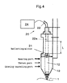
- Fig. 4 shows a general configuration of another probe type shape measuring sensor according to the present invention.
- Fig. 5 is a sectional view of part of Fig. 4.
- Fig. 6 illustrates the characteristics of the probe head shown in Fig. 2.
- Fig. 7 shows sketches of the behavior of the measuring probe during a measurement.
- Fig. 8 is a diagram showing the configuration of the NC processing equipment according to the present invention.
- Fig. 2 shows the general configuration of the probe type shape measuring sensor according to the present invention.
- the probe type shape measuring sensor according to the present invention is composed of a probe head 10 and a displacement measuring device 20.
- the probe head 10 supports a probe 2 that can contact a workpiece 1, with an extremely low resistance to sliding, in a manner such that it can move horizontally, and also drives the probe in the direction of the workpiece 1, horizontally with a small load.
- the displacement measuring device 20 measures the horizontal displacement of the probe 1 in a highly accurate manner without contact.
- a spherical sapphire ball is installed for the purpose of reducing the friction with the workpiece 1 and preventing wear.
- Fig. 3 is a sectional view of part of the probe head 10 in Fig. 2.
- the probe head 10 is composed of a long thin probe shaft 12, air bearings 14a, 14b and gas feeding means 16, 17.
- a probe 2 is mounted, and the shaft has a step in cross section 11a at an intermediate portion.
- the probe shaft 12 is composed of a large portion at the end where the probe 2 is installed, and a smaller portion at the opposite end, between which there is a step 11a in cross section.
- the size of the cross sectional difference 11a is set so that the horizontal driving force, created by the difference between the different cross sectional areas is a very small load (for instance, about 500 mgf or less) in a predetermined range.
- the probe shaft has a rectangular cross section, however, the present invention is not limited only to this shape, but it can be circular.
- Air bearings 14a, 14b are provided on each side of step 11a in cross section. These air bearings 14a, 14b have a high stiffness in the radial direction. In addition, these air bearings 14a, 14b make the probe shaft 12 float and reduce the resistance to sliding thereof using the first pressurizing gas (for example, compressed air) supplied through means 17 of feeding air (for example, a first passage way 15a in the main probe unit 15 connected to an air source, regulator, or electro-pneumatic regulator). After making the probe shaft 12 float, the first pressurizing gas is exhausted in both directions through the gaps between the air bearings 14a, 14b and the probe shaft 12.
- the first pressurizing gas for example, compressed air supplied through means 17 of feeding air (for example, a first passage way 15a in the main probe unit 15 connected to an air source, regulator, or electro-pneumatic regulator).
- the gas feeding means 16 is composed, for instance, of a second passage way 15b provided in the main probe unit 15 connected to an air source, regulator, or electro-pneumatic regulator, and supplies a second pressurizing gas (for example, another source of compressed air) to the location of the change 11a in cross section of the probe shaft 12. Because this gas feeding means 16 keeps the pressure of the second pressurizing gas to be supplied to the location of the change in cross section 11a, at a constant value, the horizontal driving force produced by the difference in cross sectional areas of the step 11a can be maintained at a very small constant load within a predetermined range.
- a second pressurizing gas for example, another source of compressed air
- a horizontal returning force is created by the difference in the sizes of the gaps of air bearings 14a, 14b. Therefore, in this example, an enlarged portion 13 of which the size is larger than the cross section of the probe shaft, is provided at the end 12b (right end in this figure) of the probe shaft 12. However, this portion can be eliminated.
- the sensor according to the present invention can be installed and'used, in a vertical or inclined direction as well as horizontally.
- Fig. 4 shows the general configuration of another probe type shape measuring sensor according to the present invention.
- Fig. 5 is a sectional view of part of Fig. 4.
- a third pressurizing gas is supplied from the gas feeding means 16b, independently from first and second pressurizing gasses, and the pressure of the third pressurizing gas produces a returning force in the opposite direction to the direction of the driving force of the second pressuring gas, thereby the effect of the weight of the probe shaft 12 is canceled out.
- the returning force is composed of a driving force produced by the difference in the gaps between the probe shaft 12 and air bearings 14a, 14b, and another driving force created by a difference in the areas of the step 11b by the pressure of the third pressurizing gas which is supplied to the location of the step 11b of the probe shaft, from the gas feeding means 16b.
- the displacement measuring device 20 is composed of a reflecting mirror 21, optical fiber 22 and laser interferometric displacement meter 24.
- the reflecting mirror 21 is a flat mirror installed at the end 12b of the probe shaft 12, perpendicular to the center line.
- the optical fiber 22 is provided with an emitting end surface 22a opposite the reflecting mirror 21 with a distance L between them.
- the optical fiber 22 is flexible, sufficiently long, and the surface at the other end of the fiber is connected to the laser interferometric displacement meter 24 via, for instance, an optical connector etc.
- the laser interferometric displacement meter 24 is composed of, for example, a semiconductor laser, a photodetecting element, an optical fiber coupler, etc., and transmits laser light via the optical fiber 22 to the reflecting mirror 21, and measures the position of the reflecting mirror using the light reflected from the reflecting mirror 21 to the end surface 22a of the optical fiber.
- the laser interferometric displacement meter 24 can be used to measure the position of the reflecting mirror 21 with an accuracy as high as 0.1 ⁇ m. Since the laser light is transmitted through the optical fiber 22 to the reflecting mirror, the movable portions of the probe head 10 and the laser interferometric displacement meter 24 can be made compact.
- the probe 2 is supported by the probe head 10 with an extremely low resistance to sliding, in a manner such that it can move, and the probe can be driven towards the workpiece 1. Therefore the probe 2 can precisely follow the profile of the surface of the workpiece 1 while making contact with the surface with a very small load (about 500 mgf).
- a very small load about 500 mgf.
- the displacement of the probe 2 in the direction of the workpiece is measured using the displacement measuring device 20 in a highly accurate manner without contact, a sub-micron accuracy of about 0.1 ⁇ m can be obtained.
- the long thin probe shaft 12 with the probe 2 installed at one end 12a is supported by air bearings 14a, 14b and these air bearings 14a, 14b have a high stiffness in the radial direction, and the probe shaft 12 is made to float by the first pressurizing gas (compressed air). Therefore the probe shaft 12 can be supported with an extremely low resistance to sliding in the direction of the workpiece while the stiff bearings prevent the shaft as it slides from being tilted by the friction of the probe 2 as it slides, so that measurement errors can be prevented from increasing.
- the steps 11a, 11b are located at intermediate portions of the probe shaft, and the gas feeding means 16a, 16b supply the locations of the steps 11a, 11b with second and/or third pressurizing gas or gasses (other sources of compressed air), thus the driving force in the direction of the workpiece, produced by the difference in the areas at the steps 11a, 11b can be kept constant to produce a very small load within a predetermined range.
- a driving force in the direction of the work piece is produced by a difference in cross sectional areas at a step in the probe shaft, so there is absolutely no electrical drift.
- a second pressurizing gas is supplied to create the driving force in the direction of the workpiece independently from the first pressurizing gas that causes the probe shaft to float, measuring pressures can be adjusted to produce a constant very small load without lowering the stiffness of the bearings of the probe.
- the driving force in the direction of the workpiece is proportional to the pressure at the location of the step in the probe shaft and as no spring etc. is used, variations in measuring pressure associated with changes in the position of the probe can be eliminated, the linearity of the detector output is improved, and the measuring pressures can be changed freely by controlling the pressure of the second pressuring gas.
- the probe type shape measuring sensor according to the present invention and the NC processing apparatus and shape measuring method provide various advantages such as low electrical drift, excellent linearity of the detector output, small variations in the measuring pressures with variations in the position of the probe, adjustability of the measuring pressures to produce a very small load without lowering the stiffness of the bearings of the probe, ability to freely change the measuring pressures, achievement of a sub-micron accuracy of about 0.1 ⁇ m thereby obtained, easily made compact, and convenient for application to on-machine measurements.
- the waiting time can be reduced, intermediate portions between defined points can be measured, thus the number of defined points needed can be decreased, and the measuring time can be shortened.
- the NC processing apparatus should not be limited only to the probe type shape measuring sensor, but it also includes such configurations as that a second sensor is installed or can be installed. That is, although the present invention has been described referring to several preferred embodiments, the scope of rights included in the present invention should be understood not to be limited only to these embodiments. Instead, the scope of rights of the present invention should include all modifications, corrections and equivalent entities included in the scope of the attached claims.
Landscapes
- Physics & Mathematics (AREA)
- General Physics & Mathematics (AREA)
- Length Measuring Devices With Unspecified Measuring Means (AREA)
Abstract
Description
- The present invention relates to a probe type shape measuring sensor, and a NC processing equipment and a shape measuring method using the sensor.
- When a workpiece must be manufactured precisely it is essential to have a technology for measuring the shape of the workpiece on the processing machine, i.e. so-called on-machine measurement technology. Such an on-machine measurement technology can improve the accuracy of the processing by eliminating the positioning errors which occur when the workpiece is removed and replaced, and at the same time the processing efficiency can be improved and the measurements can be automated and the manpower required for preparations can be saved.
- Apparatus for measuring the shape of a workpiece, known in the prior art, include a probe type shape measuring sensor wherein the tip of a measurement probe touches the surface of the workpiece and measures the shape thereof. Such probe type shape measuring sensors are classified generally into analog and digital types depending on the means of detecting the position of the measurement probe.
- In an analog-type shape measuring sensor, for example in an electric micrometer, displacements in the position of the probe are converted into analog electric values by detecting variations in the voltage of a differential transformer, electrostatic capacitance, resistance of a strain gauge, etc. However, because the system uses analog signals, large drifts in the output occur and the detected output is not very linear, so sub-micron accuracy such as about 0.1 µm cannot possibly be obtained if the overall distance moved by the sensor is about 100 µm.
- Conversely, a digital-type shape measuring sensor, such as for example a digital micrometer, measures displacements in the position of the measurement probe, digitally using an optical scale, magnetic scale or a length measuring system using optical interferometer, therefore a maximum resolution of about 10 nm can be achieved.
- However, even with the digital-type shape measuring sensor, the measurement probe must be supported by a linear ball bearing or an air slide, to enable it to move in the axial direction, and a spring or air pressure is used to press the probe onto the workpiece. Consequently, the measurement pressure fluctuates as the probe moves, and a large pressure is needed for the measurement and the pressure cannot be controlled freely, and this is a practical problem.
- More explicitly, a spring applies a minimum pressure of about 10 grams which is too large to obtain a high accuracy, and because the spring force varies depending on the displacement of the probe resulting in variations in the pressure, there are large measurement errors, which is also another problem. When air pressure is applied, although the measurement pressure can be reduced by using a low air pressure, the minimum is still about 1 gram. There is another problem that if the air pressure is reduced, the stiffness of the air slide is also reduced, allowing the probe to tilt excessively, and the measurement errors are increased. Therefore, even with a digital system, a sub-micron accuracy of about 0.1 µm cannot be achieved.
- To obtain a high accuracy of the sub-micron order, it is desirable that the measurement pressure should be as low as possible (preferably, about 500 milligrams or less). And to prevent a deterioration in the measurement accuracy caused by sideways displacements of the probe during a measurement, the measurement pressure should preferably be freely adjustable. These requirements have been shown by analysis.
- To satisfy these requirements, a high-accuracy shape measuring device typically as shown in Fig. 1 has been developed. This shape measuring device uses a minimum measuring force as small as about 50 milligrams, and measures the displacement of the measurement probe with a laser interferometer, thereby achieving a measurement accuracy of about 0.1 µm. However, with the device shown in Fig. 1, many optical elements such as moving mirrors and prisms are required, so the device itself becomes very large and delicate, therefore the device has the problem that it cannot be installed on a processing machine for making measurements on the machine.
- When the aforementioned probe type shape measuring sensor is installed on a conventional NC processing device, a personal computer etc. is used to output a command to define the position of each point to be measured, to the NC control device. And the probe is stopped for a predetermined time at the defined point, and when the position of the probe is considered to have stabilized, the output from the shape measuring sensor is saved to determine the shape of a workpiece. However, according to this means, the times required to move the probe to the defined positions and the waiting times during which the probe is stopped accumulate, a long time is required. In addtion as intermediate points between points cannot be measured, a large number of defined points are required, so causing the problem that very long time is required to complete the measurements.
- The present invention is aimed at solving the various problems mentioned above. That is, an object of the present invention is to provide a probe type shape measuring sensor with a small electric drift, excellent linearity of the output, small variations in measurement pressures during changes in the position of the probe, without decreasing the stiffness of the probe bearing, measurement pressures that can be adjusted to a constant very small load and changed freely, thus a sub-micron accuracy of about 0,1 µm can be obtained, and also capable of being made compact, and easily applied to on-machine measurements, and an NC processing apparatus and a shape measuring method using the sensor.
- Another object of the present invention is to offer an NC processing apparatus and a shape measuring method using the aforementioned probe type shape measuring sensor, in which the waiting time is reduced, and the shape between defined points can be measured, thereby enabling the number of necessary defined points to be reduced and the measuring time shortened.
- According to the present invention, a probe type shape measuring sensor is provided and characterized to be composed of a probe head (10) that supports a probe (2) that contacts a workpiece (1) in such a way that the probe can move towards the workpiece with an extremely low resistance to sliding and drives the probe towards the workpiece with a very low force, and a displacement measuring device (20) that measures the displacement of the probe, very accuracy and without contact.
- Because the probe (2) is supported by the probe head (10) so that it can move with an extremely low resistance to sliding and is driven towards the workpiece, the probe can trace the surface of the workpiece precisely while contacting the surface of the workpiece with a very low load (about 500 mgf or less). Furthermore, by measuring the displacement of the probe with the displacement measuring device (20) which is very accurate and requires no contact, a sub-micron accuracy of about 0.1 µm can be achieved.
- According to a preferred embodiment of the present invention, the aforementioned probe head (10) is provided with a long thin probe shaft (12) with the probe installed at one end (12a) thereof and a step in cross section (11a, 11b) at an intermediate portion thereof, air bearing (14a, 14b) that are disposed at each side of the above-mentioned step and support the probe shaft, and a means (16) of feeding air that supplies gas at the first pressure to the location of the aforementioned step; the above-mentioned air bearings have a high stiffness in the radial direction and are disposed in such a way that the gas at the first pressure causes the probe shaft to float to reduce its resistance to sliding; the aforementioned gas feeding means keeps the pressure or pressures of gas or gasses at second and/or third pressures supplied to the location of the aforementioned step at a constant value or constant values, thereby the gas feeding means produces a driving force due to the step in the direction of the workpiece being measured and keeps the load very small within a predetermined range.
- The long thin probe shaft (12) with the probe attached at one end (12a) thereof is supported by the air bearings (14a, 14b), and the first pressurizing gas for instance, compressed air increases the stiffness of these air bearings in the radial direction, and causes the probe shaft to float. Thus the probe shaft can be supported with an extremely low resistance to sliding and can move towards the workpiece while the probe shaft is prevented from being tilted by the friction between the probe and the workpiece, therefore, measurement errors can be prevented from increasing. In addition, the steps (11a, 11b) are constructed at intermediate portions of the probe shaft, and the means (16a, 16b) of feeding gas supplies the location of the steps with second and/or third pressurizing gas or gasses (for instance, another sources of compressed air). Thereby the driving force produced by the difference in sectional areas of the shaft in the direction of the workpiece can be maintained at a constant very low load within a predetermined range.
- Therefore, because the driving force is created by the difference in sectional areas due to the step in the shaft in the direction of the workpiece, a drift of the output is completely eliminated. Also, because second and/or third pressurizing gas or gasses are supplied to produce the driving force in the direction of the workpiece, independently from the first pressurizing gas that keeps the probe shaft floating, the measuring pressure can be adjusted to a constant very small load without degrading the stiffness of the bearings of the probe. Furthermore, as the driving force in the direction of the workpiece is proportional to the pressure difference in shaft cross sectional areas and no springs etc. are used, variations in the measuring force caused by changes in the position of the probe can be eliminated, so that the linearity of the output is improved, and the measuring force can be freely changed by controlling the pressures of second and/or third pressurizing gas or gasses.
- The aforementioned driving force given to the probe shaft in the direction of the work piece should preferably be about 10 mgf or more and no more than about 500 mgf. If the driving force in the direction of the workpiece exceeds about 500 mgf, friction between the probe and the workpiece increases, resulting in a large tilt of the probe shaft, so a sub-micron accuracy of about 0.1 µm cannot be obtained. Also if it is less than about 10 mgf, the probe may often bounce, so that the measuring speed is greatly reduced.
- The above-mentioned displacement measuring device (20) is provided with a reflecting mirror (21) installed at the other end (12b) of the probe shaft, an optical fiber (22) with its emitting end surface (22a) located opposite and apart from the aforementioned reflecting mirror, and a laser interferometric displacement meter (24) that transmits laser light through the above-mentioned optical fiber to the aforementioned reflecting mirror and measures the position of the reflecting mirror by light reflected between the reflecting mirror and the emitting end surface.
- In this configuration, using the laser interferometric displacement meter (24), the position of the reflecting mirror (21) can be measured with a high accuracy of 0.1 µm. In addition, because the laser light is transmitted to the reflecting mirror through the optical fiber (22), the moving parts of the probe head (10) and the laser interferometric displacement meter (24) can be made compact. Moreover, because the probe shaft (12) can be made with a light weight, the response time for measurements is reduced, so high-speed measurements can be achieved.
- Also because the main unit of the laser interferometric displacement meter can be located away from the probe head, the measuring instrument can be protected from thermal distortion, so that highly accurate measurements can be achieved.
- According to another aspect of the present invention, the invention is provided with NC processing equipment, that incorporates the aforementioned probe type shape measuring sensor, and moves the sensor by a numerical control system relative to the workpiece, thereby measuring the shape of the workpiece without needing to remove the workpiece which is to be processed henceforth.
- This configuration enables a sub-micron accuracy of about 0.1 µm to be achieved, and because the probe type shape measuring sensor that can be made compact and is installed on the NC processing equipment, on-machine measurements become possible, positioning errors that may otherwise occur when the workpiece is removed and remounted can be eliminated so improving the accuracy of the processing, and the time and manpower required for preparations can be saved and the processing efficiency can be improved by automation.
- According to still another embodiment of the present invention, the aforementioned NC processing equipment is provided with an interface that outputs the coordinates of each numerical control axis and the signals from the probe type shape measuring sensor, in real time for use outside the equipment.
- Using this configuration, the coordinates of each numerical control axis and the output signals from the probe type shape measuring sensor can be saved in a computer etc. outside the equipment, through the interface, in real time while the probe type shape measuring sensor is being driven and moved to obtain a profile of the workpiece, without needing to stop the NC control equipment at a defined point for positioning. Therefore, the number of defined points can be reduced and the time required for the measurements is decreased.
- Further according to the present invention, the probe (2) in contact with the workpiece (1) is installed at one end (12a) of the long thin probe shaft (12) which has steps (11a, 11b), and while the aforementioned probe shaft is supported by the first pressurizing gas so as to be able to move with an extremely low friction, the shaft is maintained with a high stiffness in the radial direction, second and/or third pressurizing gas or gasses are supplied to the location of the above-mentioned steps, the driving force of the probe shaft in the direction of the workpiece is kept very small by the pressure or pressures thereof, and the displacement of the probe in the direction of the workpiece is measured with the laser interferometric displacement meter (24).
- According to this method, the probe (2) is supported so it can move with an extremely low resistance to sliding, and is driven in the direction of the workpiece. Thereby the probe can precisely follow the profile of the surface of the workpiece while the probe is kept in contact with the surface of the workpiece with a very small load. In addition, by measuring the displacement of the probe with the laser interferometric displacement meter (24) with a high accuracy in a manner which requires no contact, a sub-micron accuracy of about 0.1 µm can be achieved. Independently from the first pressurizing gas that makes the probe shaft float, second and/or third pressurizing gas or gasses are supplied that produce the driving forces in the direction of the workpiece. Therefore, the measuring pressure can be adjusted to maintain a constant, very small load without reducing the stiffness of the bearings of the probe. In addition, because the driving force in the direction of the workpiece is proportional to the pressure applied to the portion where there is a step, variations in the measuring pressure that might otherwise result from changes in the position of the probe can be eliminated, so that the linearity of the output is improved, and furthermore, the measuring pressure can be changed freely by controlling the pressure or pressures of the second and/or third pressurizing gas or gasses.
- Moreover, the present invention also provides a shape measuring method wherein the above-mentioned probe type shape measuring sensor is built into an NC processing device, and the sensor is moved relative to the workpiece by a numerical control system, and thus the shape of the workpiece after processing can be measured without removing it from the equipment.
- This method makes on-machine measurement possible, eliminates positioning errors due to removing and remounting the workpiece, thereby increasing the accuracy of processing, and furthermore, the manpower required for preparation at that time can be saved, thereby improving the efficiency of processing and, at the same time the operation can be automated.
- In the aforementioned shape measuring method, it is preferred that the above-mentioned NC processing equipment is not stopped but is used to measure the shape of the workpiece by directly outputting in real time the coordinates the numerical control axes of the aforementioned NC processing equipment together with the output signals from the above-mentioned probe type shape measuring sensor to external equipment.
- Using this method, the coordinates of the numerical control axes of the NC processing device and the output signals from the probe type shape measuring sensor can be stored in a computer etc. outside the equipment, in real time as the probe type shape measuring sensor is being used to obtain a profile of the workpiece. Therefore, the shape of the workpiece can be measured, and the measuring time can be reduced without needing to stop the NC processing device.
- Other objects and advantages of the present invention are revealed in the following paragraphs referring to the attached drawings.
- Fig. 1 shows the configuration of a conventional high-accuracy shape measuring device.
- Fig. 2 shows a general configuration of a probe type shape measuring sensor according to the present invention.
- Fig. 3 is a sectional view of part of Fig. 2.
- Fig. 4 shows a general configuration of another probe type shape measuring sensor according to the present invention.
- Fig. 5 is a sectional view of part of Fig. 4.
- Fig. 6 illustrates the characteristics of the probe head shown in Fig. 2.
- Fig. 7 shows sketches of the behavior of the measuring probe during a measurement.
- Fig. 8 is a diagram showing the configuration of the NC processing equipment according to the present invention.
- Preferred embodiments of the present invention are described below. In each drawing, the same portions are identified with the same reference numbers, and no duplicate descriptions are given.
- Fig. 2 shows the general configuration of the probe type shape measuring sensor according to the present invention. As shown in this figure, the probe type shape measuring sensor according to the present invention is composed of a probe head 10 and a displacement measuring device 20. The probe head 10 supports a probe 2 that can contact a workpiece 1, with an extremely low resistance to sliding, in a manner such that it can move horizontally, and also drives the probe in the direction of the workpiece 1, horizontally with a small load. The displacement measuring device 20 measures the horizontal displacement of the probe 1 in a highly accurate manner without contact. At the tip of the probe 2 (contact portion), in this example, a spherical sapphire ball is installed for the purpose of reducing the friction with the workpiece 1 and preventing wear.
- Fig. 3 is a sectional view of part of the probe head 10 in Fig. 2. As shown in this figure, the probe head 10 is composed of a long thin probe shaft 12, air bearings 14a, 14b and gas feeding means 16, 17.
- At one end 12a (left end in this figure) of the long thin probe shaft 12, a probe 2 is mounted, and the shaft has a step in cross section 11a at an intermediate portion. The probe shaft 12 is composed of a large portion at the end where the probe 2 is installed, and a smaller portion at the opposite end, between which there is a step 11a in cross section. The size of the cross sectional difference 11a is set so that the horizontal driving force, created by the difference between the different cross sectional areas is a very small load (for instance, about 500 mgf or less) in a predetermined range. In this example, the probe shaft has a rectangular cross section, however, the present invention is not limited only to this shape, but it can be circular.
- Air bearings 14a, 14b are provided on each side of step 11a in cross section. These air bearings 14a, 14b have a high stiffness in the radial direction. In addition, these air bearings 14a, 14b make the probe shaft 12 float and reduce the resistance to sliding thereof using the first pressurizing gas (for example, compressed air) supplied through means 17 of feeding air (for example, a first passage way 15a in the main probe unit 15 connected to an air source, regulator, or electro-pneumatic regulator). After making the probe shaft 12 float, the first pressurizing gas is exhausted in both directions through the gaps between the air bearings 14a, 14b and the probe shaft 12.
- The gas feeding means 16 is composed, for instance, of a second passage way 15b provided in the main probe unit 15 connected to an air source, regulator, or electro-pneumatic regulator, and supplies a second pressurizing gas (for example, another source of compressed air) to the location of the change 11a in cross section of the probe shaft 12. Because this gas feeding means 16 keeps the pressure of the second pressurizing gas to be supplied to the location of the change in cross section 11a, at a constant value, the horizontal driving force produced by the difference in cross sectional areas of the step 11a can be maintained at a very small constant load within a predetermined range.
- In Fig. 3, a horizontal returning force is created by the difference in the sizes of the gaps of air bearings 14a, 14b. Therefore, in this example, an enlarged portion 13 of which the size is larger than the cross section of the probe shaft, is provided at the end 12b (right end in this figure) of the probe shaft 12. However, this portion can be eliminated. In addition, by setting this returning force appropriately, the sensor according to the present invention can be installed and'used, in a vertical or inclined direction as well as horizontally.
- Fig. 4 shows the general configuration of another probe type shape measuring sensor according to the present invention. Fig. 5 is a sectional view of part of Fig. 4.
- When the sensor of the present invention shown in Fig. 3, is installed and operated in a direction other than horizontal, such as in a vertical direction, the weight of the probe shaft 12 is added to the measuring force, so the measurement cannot be carried out with a very small load. Consequently, as shown in Fig. 4, a third pressurizing gas is supplied from the gas feeding means 16b, independently from first and second pressurizing gasses, and the pressure of the third pressurizing gas produces a returning force in the opposite direction to the direction of the driving force of the second pressuring gas, thereby the effect of the weight of the probe shaft 12 is canceled out.
- In Fig. 5, the returning force is composed of a driving force produced by the difference in the gaps between the probe shaft 12 and air bearings 14a, 14b, and another driving force created by a difference in the areas of the step 11b by the pressure of the third pressurizing gas which is supplied to the location of the step 11b of the probe shaft, from the gas feeding means 16b. By setting this returning force appropriately, it is possible to install the sensor of the present invention in a vertical or inclined direction as well as horizontally, and make measurements with a very small load.
- As shown in Figs. 2, 3, 4 and 5, the displacement measuring device 20 is composed of a reflecting mirror 21, optical fiber 22 and laser interferometric displacement meter 24.
- The reflecting mirror 21 is a flat mirror installed at the end 12b of the probe shaft 12, perpendicular to the center line. The optical fiber 22 is provided with an emitting end surface 22a opposite the reflecting mirror 21 with a distance L between them. The optical fiber 22 is flexible, sufficiently long, and the surface at the other end of the fiber is connected to the laser interferometric displacement meter 24 via, for instance, an optical connector etc.
- The laser interferometric displacement meter 24 is composed of, for example, a semiconductor laser, a photodetecting element, an optical fiber coupler, etc., and transmits laser light via the optical fiber 22 to the reflecting mirror 21, and measures the position of the reflecting mirror using the light reflected from the reflecting mirror 21 to the end surface 22a of the optical fiber.
- Using this configuration, the laser interferometric displacement meter 24 can be used to measure the position of the reflecting mirror 21 with an accuracy as high as 0.1 µm. Since the laser light is transmitted through the optical fiber 22 to the reflecting mirror, the movable portions of the probe head 10 and the laser interferometric displacement meter 24 can be made compact.
- In the aforementioned configuration, the probe 2 is supported by the probe head 10 with an extremely low resistance to sliding, in a manner such that it can move, and the probe can be driven towards the workpiece 1. Therefore the probe 2 can precisely follow the profile of the surface of the workpiece 1 while making contact with the surface with a very small load (about 500 mgf). In addition, because the displacement of the probe 2 in the direction of the workpiece is measured using the displacement measuring device 20 in a highly accurate manner without contact, a sub-micron accuracy of about 0.1 µm can be obtained.
- In addition, the long thin probe shaft 12 with the probe 2 installed at one end 12a is supported by air bearings 14a, 14b and these air bearings 14a, 14b have a high stiffness in the radial direction, and the probe shaft 12 is made to float by the first pressurizing gas (compressed air). Therefore the probe shaft 12 can be supported with an extremely low resistance to sliding in the direction of the workpiece while the stiff bearings prevent the shaft as it slides from being tilted by the friction of the probe 2 as it slides, so that measurement errors can be prevented from increasing. In addition, the steps 11a, 11b are located at intermediate portions of the probe shaft, and the gas feeding means 16a, 16b supply the locations of the steps 11a, 11b with second and/or third pressurizing gas or gasses (other sources of compressed air), thus the driving force in the direction of the workpiece, produced by the difference in the areas at the steps 11a, 11b can be kept constant to produce a very small load within a predetermined range.
- The following paragraphs describe the embodiments and analysis results of the aforementioned probe type shape measuring sensor, and the NC processing equipment and the shape measuring method using the sensor.
- 1. Analysis of slipping and tilting errors of the
measurement probe when measuring a slope
The above-mentioned Fig. 2 shows a general view of
the newly developed shape measuring sensor. A sapphire
ball is installed at the tip of the measuring probe, and
the probe shaft 12 is supported by air slides (air bearings
14a, 14b). The reflecting mirror 21 is mounted on the
opposite end of the probe shaft, and the optical fiber
laser interferometric displacement meter (displacement
measuring device 20) measures the displacement of the probe,
thereby the shape of a workpiece can be measured in
principle. The measuring pressure can be varied within a
range of about 0 mgf to 500 mgf by controlling the air
pressure using an electro-pneumatic regulator.Fig. 6 shows the characteristics of the newly
developed probe head. The measured air pressures of the
second pressurizing gas (driving air) supplied to the
location of the step 11a is shown on the abscissa, and the
measured driving force is the ordinate. In Fig. 6, the
horizontal driving force is slightly negative when the air
pressure is less than about 9.4 kPa. It can also be seen
that when the air pressure of the driving air exceeds about
9.4 kPa, the horizontal driving force increases precisely
in proportion to the air pressure. It can therefore be
understood that since the horizontal driving force is
precisely proportional to the pressure at the location of
the step and no spring etc. is used, variations in the
measuring pressure when the position of the probe changes
can be eliminated, the linearity of the detector output is
improved, and the measuring pressure can be changed freely
depending on the pressure of the second pressurizing gas.When the probe type shape measuring sensor is used
for measuring a shape, slipping and tilting of the probe
during the measurement will cause measurement errors,
therefore, the sensor must be structurally designed so as
to make such an error less than the specified measurement
error. Figs. 7A and 7B are typical illustrations to show
the condition of the measuring probe during a measurement.
Define r as the radius of curvature at the tip of the probe
shaft, and assume that a slope with an angle is moving
at a constant speed v during a measurement. Also assume
that during the measurement, an external force Fx from an
air slide is acting in the radial direction, another
external force Fy is acting in the axial direction, and the
reaction forces from the workpiece consist of a vertical
reaction force N and a frictional force µN, and also
assume that the probe shaft slips a distance p along the
slope of the workpiece and tilts at an angle about the
center of the ball at the tip of the probe. Then, the
slipping and tilting error δ of the probe shaft during the
measurement is given by the following formula by solving
the equilibrium equations of the probe shaft in the radial
and axial directions and the equilibrium equation of the
moment of the probe shaft about the same center as above.
The first term of the above equation gives the error caused by the probe shaft slipping, and the second term is the error due to tilting. It can be understood that when the angle of inclination of the slope of the workpiece being measured is rather large, the measurement error due to an error in the geometrical position of the measuring probe is determined mainly by the error due to slipping, because the ratio of the axial resistance to the radial stiffness of the air slide, ξ, is a first order term.Therefore, to achieve a measuring error δ<0.1 µm for the condition that the maximum angle of inclination max = 60°, the dynamic friction coefficient µ = 0.3 and the stiffness of the air bearing k = 0.15N/µm, measuring error δ<0.1 µm is given by the following equation.

- 2. Analysis of the maximum scanning speed
When a shape is measured by a probe, particularly for
a large workpiece, there is a need to increase the
measuring speed. In this regard, when a sine surve shaped
surface with a maximum amplitude of A is measured by a
probe with a mass m with a measuring pressure Fy and a
measuring data pitch d, the maximum scanning speed Vmax for
the probe to be able to closely follow the profile of the
surface of the workpiece during a measurement is given by
the following equation.
- 3. Design of the data input/output interface When a shape measuring sensor is installed on a processing machine and carries out a measurement, an ordinary method known in the prior art is that NC data are transmitted from a personal computer to the NC controller, and after confirming that the machine has reached the demanded position, the displacement of the shape measuring sensor at the position is input to the personal computer. According to this method, however, a long time is spent to make a measurement because the machine must stop at each measuring point and perform a measurement. In this connection, according to the present invention as shown in Fig. 8, information about the current position is output directly from the processing machine, and at the same time, the displacement of the shape measuring sensor is input into the personal computer, thereby the processing machine need not be stopped at each measuring point, and the machine can measure the displacements in real time. In this way, a high-accuracy and high-speed measurement can be achieved.
- 4. Correction for tilting of an installed sensor, and
correction for the shape of the ball at the tip of the
probe
When a shape measuring sensor is installed on a
processing machine, there is a slight displacement between
the axes of the processing machine and the sensor. The
measuring error caused by this displacement increases as
the angle of inclination of a workpiece becomes large, and
for the purpose of making highly accurate measurements, a
correction is required by processing the data.
Consequently, when a sensor was installed a tilting error
and a probe-tip ball shape error were estimated and a
correction was made using a reference ball and assuming a
linear relationship between the variations of the
coordinates of the machine and the outputs of the sensor.The ratio of the sensor output η to the coordinate
displacement δ (value for linearity correction), k, is
given by the following equation, where at a measuring point
of a workpiece the surface is inclined at an angle 1 in
the XZ plane and 2 in the YZ plane, and when the sensor
is installed, it is inclined at an angle α1 in the XZ
plane and α2 in the YZ plane, and when the processing
machine is displaced by a distance δ along the Z axis, the
output of the sensor is η.
- 5. Evaluation of the performance of the shape measuring sensor To evaluate the performance of a shape measuring sensor manufactured according to the present invention, the shape of the reference ball was measured three times for each of the X and Y directions and in both the positive and negative directions, that is, a total of four directions, and deviations of the data from a mean value curve were evaluated using standard deviations. Measurements could be carried out relatively stably under the conditions that the measuring pressure was from 100 mgf to 150 mgf and the measuring speed was from 50 mm/min to 100 mm/min. The reproducibility of the measured data in all directions of ± 3σ < 0.1µm could be achieved. Regarding the absolute accuracy of measured data, the laser interferometric displacement meter used was guaranteed to have an accuracy of ±0.1 µm over a 30 mm range, therefore, this value determines the accuracy limit.
- 6. Conclusions
According to the present invention, a high-accuracy,
small, probe type shape measuring sensor for on-machine
measurements was newly developed. Features of the sensor
that was manufactured are summarized as follows.
- The size (about 130 × 40 × 30 mm for the main unit) is appropriate for easy installation on a processing machine.
- Highly accurate measurements can be made because the measuring pressures can be controlled minutely.
- Because a laser interferometric displacement meter was used, the linearity of the data over a long stroke is higher than for conventional differential transformer systems, and the stability with respect to temperature changes is also high.
- By outputting information on the current position directly from the processing machine, measurements can be carried out in real time, so enabling high-speed measurements to be made.
- The reproducibility achieved for measured data was ±3σ<0.1 µm in 4 directions.
-
- As described above, in the probe type shape measuring sensor according to the present invention, a driving force in the direction of the work piece is produced by a difference in cross sectional areas at a step in the probe shaft, so there is absolutely no electrical drift. In addition, since a second pressurizing gas is supplied to create the driving force in the direction of the workpiece independently from the first pressurizing gas that causes the probe shaft to float, measuring pressures can be adjusted to produce a constant very small load without lowering the stiffness of the bearings of the probe. Furthermore, as the driving force in the direction of the workpiece is proportional to the pressure at the location of the step in the probe shaft and as no spring etc. is used, variations in measuring pressure associated with changes in the position of the probe can be eliminated, the linearity of the detector output is improved, and the measuring pressures can be changed freely by controlling the pressure of the second pressuring gas.
- Consequently, the probe type shape measuring sensor according to the present invention and the NC processing apparatus and shape measuring method provide various advantages such as low electrical drift, excellent linearity of the detector output, small variations in the measuring pressures with variations in the position of the probe, adjustability of the measuring pressures to produce a very small load without lowering the stiffness of the bearings of the probe, ability to freely change the measuring pressures, achievement of a sub-micron accuracy of about 0.1 µm thereby obtained, easily made compact, and convenient for application to on-machine measurements.
- Moreover, by using this probe type shape measuring sensor, the waiting time can be reduced, intermediate portions between defined points can be measured, thus the number of defined points needed can be decreased, and the measuring time can be shortened.
- The NC processing apparatus according to the present invention should not be limited only to the probe type shape measuring sensor, but it also includes such configurations as that a second sensor is installed or can be installed. That is, although the present invention has been described referring to several preferred embodiments, the scope of rights included in the present invention should be understood not to be limited only to these embodiments. Instead, the scope of rights of the present invention should include all modifications, corrections and equivalent entities included in the scope of the attached claims.
Claims (9)
- A probe type shape measuring sensor comprising a probe head (10) that supports in a movable manner a probe (2) capable of contacting a workpiece (1) with an extremely low resistance to sliding in the direction of the workpiece and drives the probe with a very small load in the direction of the workpiece, and a displacement measuring device (20) that measures the displacement of the probe in a highly accurate manner without contact.
- The probe type shape measuring sensor specified in Claim 1, wherein the probe head (10) comprises a long thin probe shaft (12) having one end (12a) to which the probe attached to and steps (11a, 11b) at intermediate positions thereof, air bearings (14a, 14b) that are provided at each side of the steps and support the probe shaft, and means (16a, 16b) of feeding air that supply the locations of the steps with second and/or third pressurizing gas or gasses,
the air bearings have a high stiffness in the radial direction and are disposed in such a manner that the probe shaft is made to float by a first pressurizing gas and a resistance to sliding thereof is reduced, the means of feeding gas maintains the pressure or pressures of second and/or third gas or gasses supplied to the locations of the steps, constant, and thereby the driving force produced by the steps in the direction of the workpiece is kept at a very small value within a predetermined range. - The probe type shape measuring sensor specified in Claim 1, wherein the driving force of the probe shaft is not less than about 10 mgf and not more than about 500 mgf.
- The probe type shape measuring sensor specified in Claim 1, wherein the displacement measuring device (20) comprises a reflecting mirror (21) installed at the other end (12b) of the probe shaft, an optical fiber (22) with an emitting end surface (22a) that faces the reflecting mirror with a distance between them, and a laser interferometric displacement meter (24) that through the optical fiber, emits laser light towards the reflecting mirror and measures the position of the reflecting mirror by the light reflected from the reflecting mirror to the emitting end surface.
- An NC processing device comprising the probe type shape measuring sensor specified in any of Claims 1 through 4, wherein the sensor is moved relative to the workpiece by a numerical control system, thereby the shape of the workpiece can be measured without needing to dismount the processed workpiece.
- The NC processing device specified in Claim 5, comprising an interface that outputs the coordinates of each numerical control axis and signals from the probe type shape measuring sensor, in real time to equipment outside the device.
- A shape measuring method, wherein a probe (2) that contacts a workpiece (1) is installed at one end (12a) of a long thin probe shaft (12) with a step (12a), and while the probe shaft is supported by a first pressurizing gas in such a manner that the probe shaft can move longitudinally with an extremely low resistance to sliding, the probe shaft is also supported in the axial direction, second and/or third gas or gasses are supplied to the location of the step, a force of driving the probe shaft in the direction of the workpiece is kept at a very small load by the pressure or pressures thereof, and a displacement of the probe in the direction of the workpiece is measured in such a manner that no contact is required, using a laser interferometric displacement meter (24).
- A shape measuring method, wherein the probe type shape measuring sensor specified in any of Claims 1 through 4 is incorporated in an NC processing device, the probe type shape measuring sensor is moved relative to a workpiece, thereby the shape of the workpiece is measured without removing the processed workpiece.
- The shape measuring method specified in Claim 8, wherein coordinates along each axis, that are output from each numerical control axis of the NC processing device, directly to outside the device, and signals output from the probe type shape measuring sensor are processed in real time, thereby the shape of the workpiece is measured without stopping the NC processing device.
Applications Claiming Priority (3)
| Application Number | Priority Date | Filing Date | Title |
|---|---|---|---|
| JP5583599 | 1999-03-03 | ||
| JP5583599 | 1999-03-03 | ||
| PCT/JP2000/001196 WO2000052419A1 (en) | 1999-03-03 | 2000-03-01 | Probe type shape measurement sensor, and nc machining device and shape measuring method using the sensor |
Publications (3)
| Publication Number | Publication Date |
|---|---|
| EP1134543A1 true EP1134543A1 (en) | 2001-09-19 |
| EP1134543A4 EP1134543A4 (en) | 2003-05-21 |
| EP1134543B1 EP1134543B1 (en) | 2007-02-07 |
Family
ID=13010054
Family Applications (1)
| Application Number | Title | Priority Date | Filing Date |
|---|---|---|---|
| EP00906598A Expired - Lifetime EP1134543B1 (en) | 1999-03-03 | 2000-03-01 | Probe type shape measurement sensor, and nc machining device and shape measuring method using the sensor |
Country Status (5)
| Country | Link |
|---|---|
| US (1) | US6539642B1 (en) |
| EP (1) | EP1134543B1 (en) |
| JP (1) | JP3932502B2 (en) |
| DE (1) | DE60033272T2 (en) |
| WO (1) | WO2000052419A1 (en) |
Cited By (5)
| Publication number | Priority date | Publication date | Assignee | Title |
|---|---|---|---|---|
| EP1793197A2 (en) * | 2005-12-02 | 2007-06-06 | Riken | Micro force measuring device, micro force measuring method, and surface shape measuring probe |
| WO2007079837A1 (en) * | 2005-12-23 | 2007-07-19 | Isis Sentronic Gmbh | Scanning system for scanning an object surface, in particular for a coordinate measurement machine |
| CN100372649C (en) * | 2002-02-28 | 2008-03-05 | 阿曼达专利及许可公司 | Automated processing unit for a working station |
| CN103302509A (en) * | 2012-03-13 | 2013-09-18 | 东芝机械株式会社 | Machining apparatus with on-machine measuring function |
| CN105180826A (en) * | 2014-05-29 | 2015-12-23 | 松下知识产权经营株式会社 | Three-dimensional Shape Measurement Apparatus |
Families Citing this family (36)
| Publication number | Priority date | Publication date | Assignee | Title |
|---|---|---|---|---|
| JP4677090B2 (en) * | 2000-11-22 | 2011-04-27 | シーケーディ株式会社 | Air bearing cylinder |
| US20050111011A1 (en) * | 2001-04-20 | 2005-05-26 | Dickinson Laurence P. | Probe for non-destructive testing |
| KR20030094938A (en) * | 2002-06-10 | 2003-12-18 | 사단법인 고등기술연구원 연구조합 | Contact type probe apparatus of on-the-machine measurement device for super-precision turning operations |
| JP4519449B2 (en) * | 2003-11-12 | 2010-08-04 | オリンパス株式会社 | Shape measuring instruments |
| GB0400144D0 (en) * | 2004-01-06 | 2004-02-11 | Renishaw Plc | Inspection system |
| US7395714B2 (en) * | 2004-09-16 | 2008-07-08 | The Boeing Company | Magnetically attracted inspecting apparatus and method using a ball bearing |
| US7313959B2 (en) * | 2005-05-25 | 2008-01-01 | The Boeing Company | Magnetically attracted apparatus, system, and method for remote bondline thickness measurement |
| JP4923441B2 (en) * | 2005-05-26 | 2012-04-25 | 株式会社ジェイテクト | Shape measuring instrument |
| JP4779448B2 (en) * | 2005-05-31 | 2011-09-28 | 株式会社ジェイテクト | Shape measuring instrument |
| JP2007064670A (en) * | 2005-08-29 | 2007-03-15 | Tokyo Seimitsu Co Ltd | Device for measuring surface shape |
| DE102005050205A1 (en) | 2005-10-20 | 2007-04-26 | Mtu Aero Engines Gmbh | Method and device for compensating position and shape deviations |
| DE102005050209A1 (en) * | 2005-10-20 | 2007-04-26 | Ott, Reinhold, Waterloo | Video signal feeding device for e.g. television set, has control unit for controlling video signal source depending on presence signal that is delivered by presence detect unit, which detects presence of person at area of feeding device |
| JP5468721B2 (en) * | 2006-02-20 | 2014-04-09 | コニカミノルタ株式会社 | Displacement detector and shape measuring device |
| JP4972764B2 (en) * | 2006-03-30 | 2012-07-11 | コニカミノルタアドバンストレイヤー株式会社 | Detector, shape measuring device, and shape measuring method |
| JP5103775B2 (en) * | 2006-03-30 | 2012-12-19 | コニカミノルタアドバンストレイヤー株式会社 | Detector, shape measuring device, and shape measuring method |
| DE102006019354B3 (en) | 2006-04-24 | 2007-07-19 | Rattunde & Co Gmbh | Profile measuring device for measuring profile of surface of tube end`s wall, has processing device changing relative position between measuring arm and surface, where relative movement direction is provided inclined to processing direction |
| US7578176B2 (en) * | 2006-12-22 | 2009-08-25 | Veeco Metrology, Inc. | Systems and methods for utilizing scanning probe shape characterization |
| US20080208524A1 (en) * | 2007-02-21 | 2008-08-28 | Elcometer Instruments Limited | Surface profile measuring instrument |
| CN101339084B (en) * | 2007-07-06 | 2012-09-19 | 鸿富锦精密工业(深圳)有限公司 | Contact measuring apparatus |
| JP4653824B2 (en) * | 2008-07-29 | 2011-03-16 | ファナック株式会社 | A machine tool system that measures the shape of a measurement object using an on-machine measuring device |
| CN101813471B (en) * | 2009-02-25 | 2014-03-26 | 鸿富锦精密工业(深圳)有限公司 | Contact measuring device |
| CN101858739B (en) * | 2009-04-10 | 2013-03-20 | 鸿富锦精密工业(深圳)有限公司 | Error compensating method and workpiece measuring method by using same |
| TWI460567B (en) * | 2009-04-24 | 2014-11-11 | Hon Hai Prec Ind Co Ltd | Method for error compensating and method for measuring workpiece using the same |
| US7911614B1 (en) | 2009-11-09 | 2011-03-22 | King Fahd University Of Petroleum And Minerals | Non-contact measurement probe |
| US8408082B2 (en) * | 2009-11-18 | 2013-04-02 | General Electric Company | Apparatus to measure fluids in a conduit |
| JP4829359B2 (en) | 2010-03-31 | 2011-12-07 | ファナック株式会社 | Calculation method of probe mounting position of on-machine measuring device |
| JP5311294B2 (en) * | 2010-04-28 | 2013-10-09 | 株式会社安川電機 | Robot contact position detector |
| JP5674149B2 (en) * | 2011-05-30 | 2015-02-25 | 新東工業株式会社 | Cumulative lead error measuring device and measuring method for ball screw shaft |
| CN102554705B (en) * | 2012-02-28 | 2013-12-11 | 天津微纳制造技术有限公司 | Compensation machining method for optical free-form surfaces |
| DE202012103951U1 (en) * | 2012-07-11 | 2012-11-15 | Buderus Schleiftechnik Gmbh | measuring machine |
| JP6200127B1 (en) * | 2016-12-09 | 2017-09-20 | 三菱重工コンプレッサ株式会社 | Compressor system with gas bearing and method for supplying gas to a compressor with gas bearing |
| PL424608A1 (en) * | 2018-02-16 | 2019-08-26 | Politechnika Białostocka | Method for determining relative static rigidity of a machining centre |
| US11041879B2 (en) | 2019-06-06 | 2021-06-22 | International Business Machines Corporation | Fluidized alignment of a semiconductor die to a test probe |
| CN114248024B (en) * | 2020-09-21 | 2024-03-19 | 深圳市吉祥云科技有限公司 | Positioning system for laser cutting |
| CN116519094B (en) * | 2023-03-01 | 2023-11-14 | 江苏杰创流量仪表有限公司 | Liquid flowmeter detection equipment and detection method |
| CN118370244A (en) * | 2024-04-12 | 2024-07-23 | 大连理工大学 | Fishery biological characteristic data detection method |
Citations (2)
| Publication number | Priority date | Publication date | Assignee | Title |
|---|---|---|---|---|
| US4509263A (en) * | 1982-07-29 | 1985-04-09 | Commissariat A L'energie Atomique | Laser sensing means for dimensional control purposes |
| DE4408912A1 (en) * | 1993-06-02 | 1994-12-08 | Zeiss Carl Fa | Coordinate measuring machine with pneumatic balancing (weight equalisation) |
Family Cites Families (14)
| Publication number | Priority date | Publication date | Assignee | Title |
|---|---|---|---|---|
| IT1135872B (en) * | 1980-07-22 | 1986-08-27 | Finike Italiana Marposs | DIAL DIMENSIONAL CONTROL OF MECHANICAL PARTS |
| JPS63229251A (en) * | 1987-03-13 | 1988-09-26 | Kitamura Mach Co Ltd | Shape measuring method for machined workpiece |
| DE3842151A1 (en) * | 1988-12-15 | 1990-06-21 | Zeiss Carl Fa | SWITCHING TYPE PROBE |
| JPH0371843A (en) | 1989-08-10 | 1991-03-27 | Yoshinori Yamauchi | Preparation of decorative panel |
| JPH0371843U (en) * | 1989-11-16 | 1991-07-19 | ||
| EP0471371B1 (en) | 1990-08-17 | 1995-04-12 | Kabushiki Kaisha Toshiba | Displacement-measuring apparatus |
| JP2788162B2 (en) * | 1993-04-06 | 1998-08-20 | 京セラ株式会社 | Non-contact length measuring device |
| DE4325743C1 (en) * | 1993-07-31 | 1994-09-08 | Heidenhain Gmbh Dr Johannes | Multi-coordinate probe |
| US5473822A (en) * | 1994-06-03 | 1995-12-12 | Js Research And Development, Inc. | Continuous air flow probe transducer gage assembly |
| GB9423176D0 (en) * | 1994-11-17 | 1995-01-04 | Renishaw Plc | Touch probe |
| ATE199042T1 (en) * | 1995-03-10 | 2001-02-15 | Heidenhain Gmbh Dr Johannes | MULTI-COORDINATE PROBE WITH EQUAL DEFLECTIONS |
| GB9605609D0 (en) * | 1996-03-16 | 1996-05-15 | Renishaw Plc | Inspection system for coordinate positioning machine |
| JPH10253308A (en) * | 1997-03-06 | 1998-09-25 | Tokyo Seimitsu Co Ltd | Contact type displacement measuring device |
| EP1024341A1 (en) * | 1999-01-29 | 2000-08-02 | Renishaw plc | Probe with vibration damped stylus |
-
2000
- 2000-03-01 WO PCT/JP2000/001196 patent/WO2000052419A1/en active IP Right Grant
- 2000-03-01 EP EP00906598A patent/EP1134543B1/en not_active Expired - Lifetime
- 2000-03-01 US US09/763,747 patent/US6539642B1/en not_active Expired - Fee Related
- 2000-03-01 JP JP2000602588A patent/JP3932502B2/en not_active Expired - Lifetime
- 2000-03-01 DE DE60033272T patent/DE60033272T2/en not_active Expired - Lifetime
Patent Citations (2)
| Publication number | Priority date | Publication date | Assignee | Title |
|---|---|---|---|---|
| US4509263A (en) * | 1982-07-29 | 1985-04-09 | Commissariat A L'energie Atomique | Laser sensing means for dimensional control purposes |
| DE4408912A1 (en) * | 1993-06-02 | 1994-12-08 | Zeiss Carl Fa | Coordinate measuring machine with pneumatic balancing (weight equalisation) |
Non-Patent Citations (1)
| Title |
|---|
| See also references of WO0052419A1 * |
Cited By (9)
| Publication number | Priority date | Publication date | Assignee | Title |
|---|---|---|---|---|
| CN100372649C (en) * | 2002-02-28 | 2008-03-05 | 阿曼达专利及许可公司 | Automated processing unit for a working station |
| EP1793197A2 (en) * | 2005-12-02 | 2007-06-06 | Riken | Micro force measuring device, micro force measuring method, and surface shape measuring probe |
| EP1793197A3 (en) * | 2005-12-02 | 2007-06-27 | Riken | Micro force measuring device, micro force measuring method, and surface shape measuring probe |
| US7685733B2 (en) | 2005-12-02 | 2010-03-30 | Riken | Micro force measurement device, micro force measurement method, and micro surface shape measurement probe |
| WO2007079837A1 (en) * | 2005-12-23 | 2007-07-19 | Isis Sentronic Gmbh | Scanning system for scanning an object surface, in particular for a coordinate measurement machine |
| CN103302509A (en) * | 2012-03-13 | 2013-09-18 | 东芝机械株式会社 | Machining apparatus with on-machine measuring function |
| TWI598178B (en) * | 2012-03-13 | 2017-09-11 | Toshiba Machine Co Ltd | Processing device and method of controlling the profiling using the same |
| CN105180826A (en) * | 2014-05-29 | 2015-12-23 | 松下知识产权经营株式会社 | Three-dimensional Shape Measurement Apparatus |
| CN105180826B (en) * | 2014-05-29 | 2017-09-22 | 松下知识产权经营株式会社 | 3 d shape testing device |
Also Published As
| Publication number | Publication date |
|---|---|
| DE60033272T2 (en) | 2007-11-29 |
| JP3932502B2 (en) | 2007-06-20 |
| EP1134543B1 (en) | 2007-02-07 |
| US6539642B1 (en) | 2003-04-01 |
| DE60033272D1 (en) | 2007-03-22 |
| WO2000052419A1 (en) | 2000-09-08 |
| EP1134543A4 (en) | 2003-05-21 |
Similar Documents
| Publication | Publication Date | Title |
|---|---|---|
| EP1134543B1 (en) | Probe type shape measurement sensor, and nc machining device and shape measuring method using the sensor | |
| US7734445B2 (en) | Shape measuring device and method | |
| US5917181A (en) | Profile measuring apparatus | |
| US7685733B2 (en) | Micro force measurement device, micro force measurement method, and micro surface shape measurement probe | |
| US5345689A (en) | Measuring probe | |
| EP0445945B1 (en) | Touch probe | |
| EP2131141B1 (en) | Shape measuring apparatus and shape measuring method | |
| JPH03180711A (en) | Probe and method, apparatus and guide means for calibrating continuously measuring probe | |
| US7535193B2 (en) | Five axis compensated rotating stage | |
| US6895682B2 (en) | Polar coordinate-based profilometer and methods | |
| JPH07260471A (en) | Measuring apparatus of surface shape | |
| JP2000304529A (en) | Probe device and shape measuring device | |
| US10584955B2 (en) | Combined workpiece holder and calibration profile configuration for precision surface profile measurement | |
| EP1299694A1 (en) | Extended range and ultra precision non contact dimensional gauge for ultra thin wafers and work pieces | |
| JP2007121260A (en) | Probe type shape measuring device and method, and rotation-restricted air cylinder suitable therefor | |
| EP0884564A2 (en) | Displacement sensor and method for producing target feature thereof | |
| US8223346B2 (en) | Optics positioning sensor system | |
| JP2966214B2 (en) | Surface profile measuring device | |
| US6307284B1 (en) | Positioning apparatus, information recording/reproducing apparatus, and inspection apparatus | |
| JP2004028684A (en) | System and method for measuring profile | |
| US20240060866A1 (en) | Indentation head for an indentation instrument | |
| JP5103775B2 (en) | Detector, shape measuring device, and shape measuring method | |
| JPH11271049A (en) | Shape measuring apparatus | |
| JPH06160075A (en) | Apparatus for measuring shape of scroll impeller | |
| JP2012181021A (en) | Contact type probe and shape measurement device |
Legal Events
| Date | Code | Title | Description |
|---|---|---|---|
| PUAI | Public reference made under article 153(3) epc to a published international application that has entered the european phase |
Free format text: ORIGINAL CODE: 0009012 |
|
| 17P | Request for examination filed |
Effective date: 20010525 |
|
| AK | Designated contracting states |
Kind code of ref document: A1 Designated state(s): DE FR GB |
|
| RAP1 | Party data changed (applicant data changed or rights of an application transferred) |
Owner name: RIKEN |
|
| A4 | Supplementary search report drawn up and despatched |
Effective date: 20030403 |
|
| 17Q | First examination report despatched |
Effective date: 20041110 |
|
| GRAP | Despatch of communication of intention to grant a patent |
Free format text: ORIGINAL CODE: EPIDOSNIGR1 |
|
| GRAS | Grant fee paid |
Free format text: ORIGINAL CODE: EPIDOSNIGR3 |
|
| GRAA | (expected) grant |
Free format text: ORIGINAL CODE: 0009210 |
|
| AK | Designated contracting states |
Kind code of ref document: B1 Designated state(s): DE FR GB |
|
| REG | Reference to a national code |
Ref country code: GB Ref legal event code: FG4D |
|
| REF | Corresponds to: |
Ref document number: 60033272 Country of ref document: DE Date of ref document: 20070322 Kind code of ref document: P |
|
| ET | Fr: translation filed | ||
| PLBE | No opposition filed within time limit |
Free format text: ORIGINAL CODE: 0009261 |
|
| STAA | Information on the status of an ep patent application or granted ep patent |
Free format text: STATUS: NO OPPOSITION FILED WITHIN TIME LIMIT |
|
| 26N | No opposition filed |
Effective date: 20071108 |
|
| PGFP | Annual fee paid to national office [announced via postgrant information from national office to epo] |
Ref country code: GB Payment date: 20090324 Year of fee payment: 10 |
|
| PGFP | Annual fee paid to national office [announced via postgrant information from national office to epo] |
Ref country code: FR Payment date: 20090325 Year of fee payment: 10 |
|
| PGFP | Annual fee paid to national office [announced via postgrant information from national office to epo] |
Ref country code: DE Payment date: 20100429 Year of fee payment: 11 |
|
| GBPC | Gb: european patent ceased through non-payment of renewal fee |
Effective date: 20100301 |
|
| REG | Reference to a national code |
Ref country code: FR Ref legal event code: ST Effective date: 20101130 |
|
| PG25 | Lapsed in a contracting state [announced via postgrant information from national office to epo] |
Ref country code: FR Free format text: LAPSE BECAUSE OF NON-PAYMENT OF DUE FEES Effective date: 20100331 |
|
| PG25 | Lapsed in a contracting state [announced via postgrant information from national office to epo] |
Ref country code: GB Free format text: LAPSE BECAUSE OF NON-PAYMENT OF DUE FEES Effective date: 20100301 |
|
| PG25 | Lapsed in a contracting state [announced via postgrant information from national office to epo] |
Ref country code: DE Free format text: LAPSE BECAUSE OF NON-PAYMENT OF DUE FEES Effective date: 20111001 |
|
| REG | Reference to a national code |
Ref country code: DE Ref legal event code: R119 Ref document number: 60033272 Country of ref document: DE Effective date: 20111001 |