EP1131995A2 - Méthode et appareil pour la traite d'animaux - Google Patents
Méthode et appareil pour la traite d'animaux Download PDFInfo
- Publication number
- EP1131995A2 EP1131995A2 EP01201932A EP01201932A EP1131995A2 EP 1131995 A2 EP1131995 A2 EP 1131995A2 EP 01201932 A EP01201932 A EP 01201932A EP 01201932 A EP01201932 A EP 01201932A EP 1131995 A2 EP1131995 A2 EP 1131995A2
- Authority
- EP
- European Patent Office
- Prior art keywords
- milking
- teat
- implement
- teat cup
- teat cups
- Prior art date
- Legal status (The legal status is an assumption and is not a legal conclusion. Google has not performed a legal analysis and makes no representation as to the accuracy of the status listed.)
- Granted
Links
Images

Classifications
-
- A—HUMAN NECESSITIES
- A01—AGRICULTURE; FORESTRY; ANIMAL HUSBANDRY; HUNTING; TRAPPING; FISHING
- A01J—MANUFACTURE OF DAIRY PRODUCTS
- A01J5/00—Milking machines or devices
- A01J5/017—Automatic attaching or detaching of clusters
- A01J5/0175—Attaching of clusters
Definitions
- the present invention relates to an implement for milking animals, such as cows, using one or more milking robots with teat cups and using one or more milking parlours.
- the invention has for its objective to provide an implement of the above type where the above disadvantage does not occur or is at least considerably reduced.
- the implement comprises stands where the teat cups are placed upon completion of the milking and at least two robot arms provided with a gripper, with the aid of which the teat cups can be coupled to the teats.
- a robot arm on each longitudinal side of the milking parlour there is provided a robot arm.
- the two robot arms are capable of being active simultaneously and, accordingly, capable of connecting two teat cups simultaneously. In this manner it is achieved that in a relatively short time the teat cups can be connected to the teats of an animal to be milked.
- the invention also relates to an implement for milking animals, such as cows, using one or more milking robots with one or more teat cups and comprising one or more milking parlours, characterized in that a teat cup is provided with at least two cables connected with the teat cup.
- a teat cup is provided with at least two cables connected with the teat cup.
- one cable extends essentially horizontally and one cable extends essentially vertically.
- the teat cups can be fastened in the implement in a simple, inexpensive, but sound way.
- the teat cup is provided with a cable fastening near the upper end and near the lower end.
- the invention also relates to an implement for milking animals, such as cows, using one or more milking robots with teat cups and using one or more milking parlours, characterized in that the teat cup is provided with a cable fastening near the upper end and one near the lower end.
- the cable extending essentially vertically has one end connected with a cable fastening provided on the milking parlour and the other end connected with the cable fastening provided near the upper side of the teat cup.
- the essentially horizontally extending cable has one end secured to a withdrawing member disposed near the milking parlour and the other end secured to the cable fastening disposed near the underside of the teat cup.
- the cable fastening for the essentially vertically extending cable is disposed on a frame beam extending in the longitudinal direction of the milking parlour.
- the cable fastening is placed at approximately 1/4 of the total length of the milking parlour as measured from the rear side of the milking parlour.
- the afore-mentioned cable fastening is, according to still another further feature of the invention, disposed near the top side of the milking parlour, preferably at a height of at least 1 m as measured from the floor of the milking parlour.
- the cable fastening of the essentially horizontally extending cable is disposed on a pneumatic cylinder of the withdrawing member.
- the pneumatic cylinder is disposed close to the floor of the milking parlour and extends in the longitudinal direction of the milking parlour.
- two cylinders there are provided two cylinders, each comprising a cable fastening.
- the implement comprises stands where the teat cups are placed upon completion of the milking and at least two robot arms, each provided with a gripper, with the aid of which the teat cups can be coupled to the teats.
- the robot arm on each longitudinal side of the milking parlour there is provided a robot arm.
- the two robot arms are capable of being active simultaneously and, accordingly, capable of connecting two teat cups simultaneously. In this manner it is achieved that in a relatively short time the teat cups can be connected to the teats of an animal to be milked.
- the gripper comprises an electromagnet and the gripper is provided with a seating recess curved in accordance with the shell of a teat cup.
- the teat cup is capable of being firmly and rapidly seized simply by energizing the electromagnet, and it is simply disengaged by de-energizing the electromagnet.
- the stands where the teat cups are placed upon completion of the milking comprise a holder provided with a conical seating corresponding with the conical shape of the underside of the teat cup.
- the conical seating it is possible to arrange a teat cup in one and the same position on the holder each time after milking. Due to the fact that the teat cups are arranged in a pre-defined position of rest on the holder, the teat cups are capable of being seized simply and efficiently by the gripper.
- a holder having two seatings is disposed close to each longitudinal side of the milking parlour.
- a hole through which the essentially horizontally extending cable is led, the arrangement being such that in the holder the cable extends in the longitudinal direction of the milking parlour to the cable fastening of the pneumatic cylinder.
- the implement comprises a robot arm equipped with a detector, such as a laser sensor, to locate the positions of the teats of an animal to be milked.
- a detector such as a laser sensor
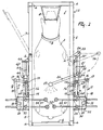
- FIG 1 shows a plan view of a milking parlour 1 with a fencing 2 enclosing an animal, a cow in the present case.
- the fencing 2 comprises posts 4 and, in between them, cross beams 5 situated at a certain distance and parallel to each other.
- the milking parlour 1 is provided with an entrance door 6 on the rear side and an exit door 7 on the longitudinal side.
- a collar 9 with a transmitter 10 which operates in conjunction with an animal recognition system (not shown).
- a milking robot 11 which comprises a robot arm 12 on each longitudinal side of the milking parlour 1.
- a vertical support 13 which is connected with a parallelogram-type hinged arm construction 14.
- the other end of the parallelogram-type hinged arm construction 14 is connected with a likewise vertically disposed supporting beam 15 connected with a cross beam 5 of the fencing 2.
- the robot arm 12 is capable of being moved vertically by means of a cylinder (not shown).
- the robot arm 12 comprises a first arm part 16 and a second arm part 18 capable of pivoting about a vertical shaft 17.
- a gripper 20 capable of rotating about a vertical shaft 19.
- a further robot arm 21 is mounted on the longitudinal side of the milking parlour 1 which is opposite to the exit door 7.
- the further robot arm 21 comprises a first arm part 22, of which one end is pivotably mounted on a vertical shaft 23 with a fork 24 fixedly connected with a post 4 of the milking parlour 1.
- the other end of the first arm part 22 is pivotably mounted on a vertical shaft 25 with a second arm part 26, whose end is provided with a detector 27 for finding the teat positions of the animal 3.
- the sensor 27 is designed as a laser detector and it is capable of being swung through an angle of approximately 150°.
- the milking robot 11 is equipped with four teat cups 28, which are arranged on a teat cup carrier 29 ( Figure 4) in pairs on both sides of the milking parlour when the milking robot 11 is out of operation.
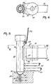
- the teat cup carrier or holder 29 is provided with a conical seating 30 corresponding with the lowermost conical part of a teat cup 28.
- a holder 29 having two conical recesses 30 situated behind each other as seen in the longitudinal direction of the milking parlour 1 on the floor beside the milking parlour 1.
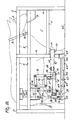
- Each teat cup 28 is also provided with means of transport 32, with the aid of which the respective teat cup 28 is kept continuously or virtually continuously in an approximately vertical position during the teat cup 28 movement to the teat cup carrier 29 and during the disconnection from the teat.
- the means of transport 32 comprise a cable 33 extending essentially horizontally and a cable 34 extending essentially vertically.
- the vertical cable 34 has one end connected with a cable fastening 35 which is disposed near the top side of the teat cup 28, on the shell 36 of the teat cup 28 ( Figure 5).
- the other end of the vertical cable 34 is connected with a cable fastening 37 which is disposed on a cross beam 5 of the fencing 2.
- the cable fastening 37 is a cylindrical body which also constitutes a guide for the end of the vertical cable 34.
- the length of the vertical cable 34 is dimensioned such that the upper part of the teat cup 28 can not come into contact with the floor 38 of the milking parlour 1.
- a cable fastening 39 in the conical part 31 on the underside of the teat cup 28 there is provided a cable fastening 39, by means of which one end of the horizontal cable 33 is connected with the teat cup 28.
- the horizontal cable 33 passes through a hole 40 in the teat cup carrier 29.
- the hole 40 has a first vertical part 41 which is provided in the centre of the conical seating 30 and, perpendicular to the first part 41, a second part 42 extending in the longitudinal direction of the milking parlour 1.
- the two horizontal cables 33 of one pair of teat cups 28 leave the teat cup carrier 29 approximately parallel to each other and extend in the longitudinal direction of the milking parlour to the withdrawing members 43.
- the withdrawing members 43 are designed as pneumatic cylinders, but they may also be hydraulic cylinders or electric equivalents of cylinders.
- the cylinders 44 have the rear side of the cylinder housing connected with a strip 45 fixedly connected with a post 4 of the fencing 2.
- the end of the piston rod 46 of the pneumatic cylinder 44 comprises a cable fastening to which the horizontal cable 33 is fastened.
- a pulley mechanism 48 is used in the present embodiment of the invention.
- the pulley mechanism 48 comprises a roller guide designed as a cable fastening 47 surrounded by the horizontal cable 33 disposed in a loop and a vertical shaft 49, to which the end of the horizontal cable 33 is fastened.
- the teat cups 28 are further provided with a milk tube 50 and a pulsation tube 51, which extend from the teat cup 28 in a loop, transversely to the longitudinal direction of the milking parlour 1, to a collector block 52.
- the collector block 52 is fitted on a cross beam 5 of the fencing 2.
- the loops in the milk tube 50 and the pulsation tube 51 are dimensioned such that the teat cups 28 are capable of moving from the position of rest on the teat cup carrier 29 as shown in Figure 4 to underneath the udder of the animal 3 as shown in Figure 3. Due to that the tubes 50 and 51 are fastened to the teat cups 28 through a loop, the animal is permitted to move during milking without the teat cups 28 being disconnected.
- the collector block 52 is furthermore provided with a milk discharge line 53 for removing the milk obtained and a vacuum line 54 for the vacuum required during milking.
- the gripper 20 comprises a block-shaped holder 55 which is rotatable about the vertical shaft 19 and which is, at the end, provided with a recess 56 ( Figures 5 and 6) curved in accordance with the shell 36 of a teat cup 28. In the vicinity of the curved recess 56, in the block-shaped holder 55, there is provided a curved electromagnet 57 which may be energized or not.
- the animal 3 After an animal 3 has entered the milking parlour 1 through the entrance door 6, the animal 3 is automatically identified by the animal recognition system by means of the transmitter 10. After the animal 3 has been identified by the animal recognition system, an amount of concentrates in the feed trough 8 may be supplied to the animal 3. Subsequently, by means of a (non-shown) computer, the robot arm 21 with the laser detector 27 thereon is swung to underneath the animal and, by means of the laser detector 27, the positions of the teats of the animal are determined and applied to the computer.
- a (non-shown) computer the robot arm 21 with the laser detector 27 thereon is swung to underneath the animal and, by means of the laser detector 27, the positions of the teats of the animal are determined and applied to the computer.
- the computer issues one or more signals to the two robot arms 12 which are disposed on the longitudinal side of the milking parlour 1 and which, acting on the basis of these signals, put the grippers 20 with the curved recess 56 to close to a shell of the teat cup 28.
- the teat cups 28 to be connected to the hind teats of the animal 3 to be milked are seized.
- the computer issues a signal to the electromagnet 57 so as to produce an electromagnetic field in the vicinity of the curved recess 56 of the gripper 20.
- the teat cup 28 When the gripper 20 has approached the metal shell 36 of a teat cup 28 to a sufficient distance, the teat cup 28 is firmly drawn against the curved recess 56 of the block-shaped holder 55 owing to the presence of the electromagnetic field. A change in the electromagnetic field is caused by the metal shell 36, whereupon a signal is issued to the computer, signifying that the teat cup 28 has been coupled.
- the last mentioned signal can also be issued by a different type of sensor, such as a contact sensor, which is disposed in the block-shaped holder 55 or by means of a position determination through the detector 27.
- the computer then issues a signal to the means of transport 32 of the relevant teat cup 28 which release the pneumatic cylinder 44 on account of this signal, all this being arranged such that the teat cup 28 can be lifted from the seating 30 of the teat cup carrier 29 by means of the robot arm 12 without being obstructed by the horizontal cable 33.
- the teat cup 28 is moved horizontally to underneath a hind teat of the animal 3 ( Figure 3).
- the vertical cable 34 swings along with the teat cup 28 and the horizontal cable 33 is also carried along.
- the gripper 20 the teat cup 28 is then connected to the teat of an animal 3 to be milked, whereupon the milking of the relevant udder quarter may start.
- there is made a faintly curved loop in the horizontal cable 33 which permits a teat cup 28 to move along when the animal 3 moves during milking.
- the robot arms 12 with their grippers 20 are put to the remaining two teat cups 28 and these are connected to the fore teats in a similar way.
- the computer issues a signal to the relevant pneumatic cylinder 44, whereupon this cylinder 44 is energized, resulting in that the corresponding horizontal cable 33 is stretched and the teat cup 28 is drawn to the seating 30 of the teat cup carrier 29.
- the teat cup 28 is kept in an approximately upright attitude by the vertical cable 34.
Landscapes
- Life Sciences & Earth Sciences (AREA)
- Animal Husbandry (AREA)
- Environmental Sciences (AREA)
- External Artificial Organs (AREA)
- Manipulator (AREA)
- Housing For Livestock And Birds (AREA)
- Catching Or Destruction (AREA)
- Cleaning In General (AREA)
- Feeding And Watering For Cattle Raising And Animal Husbandry (AREA)
Applications Claiming Priority (3)
| Application Number | Priority Date | Filing Date | Title |
|---|---|---|---|
| NL9401451A NL9401451A (nl) | 1994-09-07 | 1994-09-07 | Inrichting en werkwijze voor het melken van dieren. |
| NL9401451 | 1994-09-07 | ||
| EP95930053A EP0726703B1 (fr) | 1994-09-07 | 1995-09-05 | Dispositif et procede de traite d'animaux |
Related Parent Applications (1)
| Application Number | Title | Priority Date | Filing Date |
|---|---|---|---|
| EP95930053A Division EP0726703B1 (fr) | 1994-09-07 | 1995-09-05 | Dispositif et procede de traite d'animaux |
Publications (3)
| Publication Number | Publication Date |
|---|---|
| EP1131995A2 true EP1131995A2 (fr) | 2001-09-12 |
| EP1131995A3 EP1131995A3 (fr) | 2002-07-31 |
| EP1131995B1 EP1131995B1 (fr) | 2005-03-30 |
Family
ID=19864619
Family Applications (2)
| Application Number | Title | Priority Date | Filing Date |
|---|---|---|---|
| EP95930053A Expired - Lifetime EP0726703B1 (fr) | 1994-09-07 | 1995-09-05 | Dispositif et procede de traite d'animaux |
| EP01201932A Revoked EP1131995B1 (fr) | 1994-09-07 | 1995-09-05 | Méthode et appareil pour la traite d'animaux |
Family Applications Before (1)
| Application Number | Title | Priority Date | Filing Date |
|---|---|---|---|
| EP95930053A Expired - Lifetime EP0726703B1 (fr) | 1994-09-07 | 1995-09-05 | Dispositif et procede de traite d'animaux |
Country Status (6)
| Country | Link |
|---|---|
| US (1) | US5909716A (fr) |
| EP (2) | EP0726703B1 (fr) |
| JP (1) | JPH09506782A (fr) |
| DE (2) | DE69534123T2 (fr) |
| NL (1) | NL9401451A (fr) |
| WO (1) | WO1996007314A1 (fr) |
Families Citing this family (34)
| Publication number | Priority date | Publication date | Assignee | Title |
|---|---|---|---|---|
| NL1004406C2 (nl) * | 1996-08-01 | 1998-02-05 | Maasland Nv | Inrichting voor het automatisch melken van dieren. |
| SE9603054D0 (sv) * | 1996-08-22 | 1996-08-22 | Tetra Laval Holdings & Finance | An arrangement for and a method of performing an animal-related action |
| NL1004922C2 (nl) * | 1996-12-31 | 1998-07-01 | Prolion Bv | Inrichting en werkwijze voor het melken van dieren. |
| SE514439C2 (sv) * | 1999-05-28 | 2001-02-26 | Delaval Holding Ab | Kopplingsanordning för en spenkopp |
| NL1016023C2 (nl) * | 2000-08-25 | 2002-02-26 | Idento Electronics Bv | Melkinrichting en houder voor opname van melkbekers. |
| NL1016237C2 (nl) * | 2000-09-22 | 2002-03-25 | Rieberjo B V | Melkinrichting voorzien van reinigingsmiddelen. |
| US10874084B2 (en) | 2004-06-12 | 2020-12-29 | Gea Farm Technologies, Inc. | Safety valve for a dairy system component |
| US8025029B2 (en) * | 2004-06-12 | 2011-09-27 | Gea Farm Technologies, Inc. | Automatic dairy animal milker unit backflusher and teat dip applicator system and method |
| US8033247B2 (en) | 2004-06-12 | 2011-10-11 | Gea Farm Technologies, Inc. | Automatic dairy animal milker unit backflusher and teat dip applicator system and method |
| US8342125B2 (en) | 2004-06-12 | 2013-01-01 | Gea Farm Technologies, Inc. | Safety valve for an automatic dairy animal milker unit backflusher and teat dip applicator |
| US8117989B2 (en) | 2008-06-27 | 2012-02-21 | Gea Farm Technologies, Inc. | Milk tube dome with flow controller |
| SE527496C2 (sv) | 2004-06-22 | 2006-03-21 | Delaval Holding Ab | Gripanordning, robotarm och mjölkningsrobot |
| DE102004042088A1 (de) * | 2004-08-31 | 2006-03-02 | Westfaliasurge Gmbh | Vorrichtung zum Abziehen von Melkbechern |
| SE529127C2 (sv) | 2005-09-02 | 2007-05-08 | Delaval Holding Ab | Detekteringsarrangemang jämte -metod för en magnetisk gripanordning |
| NZ566631A (en) | 2008-03-11 | 2011-04-29 | Scott Milktech Ltd | A robotic milking system and a method of attaching milking cups |
| WO2009113884A2 (fr) * | 2008-03-11 | 2009-09-17 | Scott Milktech Limited | Bras robotisé de traite et procédé permettant d’attacher des manchons de traite |
| WO2010053577A1 (fr) * | 2008-11-10 | 2010-05-14 | Gea Farm Technologies Gmbh | Procédé et dispositif de mise en contact automatique d’un fluide avec les tétines d’un animal |
| US8578881B2 (en) * | 2008-12-22 | 2013-11-12 | Delaval Holding Ab | Arrangement for gripping at least one teat cup |
| US11723341B2 (en) | 2009-09-04 | 2023-08-15 | Gea Farm Technologies, Inc. | Safety valve for an automated milker unit backflushing and teat dip applicator system |
| US8770146B2 (en) | 2009-09-04 | 2014-07-08 | Gea Farm Technologies, Inc. | Methods and apparatus for applying teat dip to a dairy animal |
| WO2011102911A2 (fr) | 2010-02-22 | 2011-08-25 | Gea Farm Technologies, Inc. | Installations de traite équipées d'un système de protection de la canalisation à lait et procédés associés |
| US20120097107A1 (en) | 2010-02-22 | 2012-04-26 | Gea Farm Technologies, Inc. | Dairy animal milking preparation system and methods |
| DE102011001404A1 (de) * | 2011-03-18 | 2012-09-20 | Gea Farm Technologies Gmbh | Melkzeug und Melkstand mit einem solchen Melkzeug |
| EP3335548B1 (fr) | 2011-03-18 | 2021-03-10 | GEA Farm Technologies GmbH | Faisceau trayeur et salle de traite pourvue d'un tel faisceau trayeur |
| DE102012110503A1 (de) | 2012-03-14 | 2013-09-19 | Gea Farm Technologies Gmbh | Platzteiler einer Melkstandanordnung und Melkstandanordnung |
| WO2014107134A1 (fr) * | 2013-01-07 | 2014-07-10 | Delaval Holding Ab | Procédé pour système de traite et système de traite |
| WO2015065275A1 (fr) * | 2013-10-29 | 2015-05-07 | Delaval Holding Ab | Étui de gobelet-trayeur, gobelet-trayeur, et agencement pour traire automatiquement des animaux |
| US9526224B2 (en) | 2013-12-20 | 2016-12-27 | Gea Farm Technologies Gmbh | Safety valve device |
| DE102013114595A1 (de) | 2013-12-20 | 2015-06-25 | Gea Farm Technologies Gmbh | Sicherheitsventil |
| DE102014107124A1 (de) | 2014-05-20 | 2015-11-26 | Gea Farm Technologies Gmbh | Armeinrichtung für eine Melkstandanordnung zum automatischen Melken von milchgebenden Tieren, Platzteiler einer Melkstandanordnung und Melkstandanordnung |
| DE102016108300A1 (de) | 2016-05-04 | 2017-11-09 | Gea Farm Technologies Gmbh | Sicherheitsventil |
| US10499607B2 (en) * | 2016-08-17 | 2019-12-10 | Technologies Holdings Corp. | Vision system for teat detection |
| US11206805B2 (en) | 2017-11-03 | 2021-12-28 | Gea Farm Technologies Gmbh | Automated milking system safety valve arrangement |
| CN110604066A (zh) * | 2018-06-15 | 2019-12-24 | 江苏斯凯威畜牧科技有限公司 | 一种新型的挤奶用智能化棚架结构 |
Citations (3)
| Publication number | Priority date | Publication date | Assignee | Title |
|---|---|---|---|---|
| US4726322A (en) * | 1985-09-04 | 1988-02-23 | Aalbert Torsius | Milking apparatus |
| US5069160A (en) * | 1989-01-04 | 1991-12-03 | National Research Development Corporation | Automatic milking of animals |
| DE4113700A1 (de) * | 1991-04-26 | 1992-10-29 | Dieter Dipl Ing Schillingmann | Verfahren zum automatischen melken von in melkboxen stehenden milchkuehen, sowie melkbox, roboter und melkmodul zur durchfuehrung dieses verfahrens |
Family Cites Families (9)
| Publication number | Priority date | Publication date | Assignee | Title |
|---|---|---|---|---|
| US2460856A (en) * | 1941-03-13 | 1949-02-08 | Universal Milking Machine Comp | Suspension hanger |
| DE804383C (de) * | 1943-08-30 | 1951-04-23 | Melotte Ecremeuses | Tragvorrichtung fuer einen in einem Melkstand aufzuhaengenden mechanischen Haengemelker |
| NL65975C (fr) * | 1944-01-19 | |||
| EP0069560B1 (fr) * | 1981-07-07 | 1985-07-31 | The Gascoigne Group Limited | Installation de traite |
| DE3406878C1 (de) * | 1984-02-25 | 1985-06-20 | Westfalia Separator Ag, 4740 Oelde | Trag- und Abziehmechanismus fuer Melkzeuge |
| FR2593668B1 (fr) * | 1986-02-04 | 1990-05-18 | Daffini Jean Pierre | Bras porte faisceau trayeur et de commande de decrochage de celui-ci pour salle de traite mobile ou fixe |
| NL193715C (nl) * | 1987-07-23 | 2000-08-04 | Lely Nv C Van Der | Inrichting voor het melken van een dier. |
| NL8802332A (nl) * | 1988-09-21 | 1990-04-17 | Lely Nv C Van Der | Inrichting voor het melken van een dier. |
| NL9101064A (nl) * | 1991-06-20 | 1993-01-18 | Gascoigne Melotte Bv | Inrichting voor het aanleggen respectievelijk verwijderen van een stel speenbekers bij dieren. |
-
1994
- 1994-09-07 NL NL9401451A patent/NL9401451A/nl not_active Application Discontinuation
-
1995
- 1995-09-05 DE DE69534123T patent/DE69534123T2/de not_active Revoked
- 1995-09-05 EP EP95930053A patent/EP0726703B1/fr not_active Expired - Lifetime
- 1995-09-05 JP JP8509395A patent/JPH09506782A/ja active Pending
- 1995-09-05 WO PCT/NL1995/000298 patent/WO1996007314A1/fr active IP Right Grant
- 1995-09-05 DE DE69524561T patent/DE69524561T2/de not_active Expired - Lifetime
- 1995-09-05 EP EP01201932A patent/EP1131995B1/fr not_active Revoked
-
1996
- 1996-04-24 US US08/636,985 patent/US5909716A/en not_active Expired - Lifetime
Patent Citations (3)
| Publication number | Priority date | Publication date | Assignee | Title |
|---|---|---|---|---|
| US4726322A (en) * | 1985-09-04 | 1988-02-23 | Aalbert Torsius | Milking apparatus |
| US5069160A (en) * | 1989-01-04 | 1991-12-03 | National Research Development Corporation | Automatic milking of animals |
| DE4113700A1 (de) * | 1991-04-26 | 1992-10-29 | Dieter Dipl Ing Schillingmann | Verfahren zum automatischen melken von in melkboxen stehenden milchkuehen, sowie melkbox, roboter und melkmodul zur durchfuehrung dieses verfahrens |
Also Published As
| Publication number | Publication date |
|---|---|
| EP0726703A1 (fr) | 1996-08-21 |
| EP0726703B1 (fr) | 2001-12-12 |
| US5909716A (en) | 1999-06-08 |
| DE69524561D1 (de) | 2002-01-24 |
| DE69524561T2 (de) | 2002-08-01 |
| WO1996007314A1 (fr) | 1996-03-14 |
| NL9401451A (nl) | 1996-04-01 |
| EP1131995A3 (fr) | 2002-07-31 |
| DE69534123T2 (de) | 2006-02-02 |
| DE69534123D1 (de) | 2005-05-04 |
| EP1131995B1 (fr) | 2005-03-30 |
| JPH09506782A (ja) | 1997-07-08 |
Similar Documents
| Publication | Publication Date | Title |
|---|---|---|
| EP1131995B1 (fr) | Méthode et appareil pour la traite d'animaux | |
| EP0741512B1 (fr) | Procede et outil pour la traite automatique d'un animal tel qu'une vache | |
| AU665550B2 (en) | Automatic milking | |
| US6116188A (en) | Method of milking animals | |
| EP0728412B1 (fr) | Dispositif de traite d'animaux | |
| EP1258189A2 (fr) | Structure contenant une machine à traire automatique | |
| EP0880889B1 (fr) | Dispositif pour la traite d'animaux | |
| EP0900522A1 (fr) | Installation de traite | |
| NL9200091A (nl) | Melkmachine. | |
| EP1029447A2 (fr) | Dispositif de traite automatique d'animaux | |
| EP0693871B2 (fr) | Installation de traite automatique d'animaux | |
| EP0880888B1 (fr) | Dispositif de traite automatique d'animaux | |
| EP0647391B1 (fr) | Dispositif de traite automatique d'animaux | |
| EP0886466B1 (fr) | Structure comprenant une installation de traite automatique d'animaux | |
| EP1252817A2 (fr) | Construction comprenant un dispositif pour la traite automatique d'animaux |
Legal Events
| Date | Code | Title | Description |
|---|---|---|---|
| PUAI | Public reference made under article 153(3) epc to a published international application that has entered the european phase |
Free format text: ORIGINAL CODE: 0009012 |
|
| AC | Divisional application: reference to earlier application |
Ref document number: 726703 Country of ref document: EP |
|
| AK | Designated contracting states |
Kind code of ref document: A2 Designated state(s): BE DE FR GB IT NL SE |
|
| PUAL | Search report despatched |
Free format text: ORIGINAL CODE: 0009013 |
|
| AK | Designated contracting states |
Kind code of ref document: A3 Designated state(s): BE DE FR GB IT NL SE |
|
| 17P | Request for examination filed |
Effective date: 20030108 |
|
| AKX | Designation fees paid |
Designated state(s): BE DE FR GB IT NL SE |
|
| 17Q | First examination report despatched |
Effective date: 20030327 |
|
| RAP1 | Party data changed (applicant data changed or rights of an application transferred) |
Owner name: MAASLAND N.V. |
|
| GRAP | Despatch of communication of intention to grant a patent |
Free format text: ORIGINAL CODE: EPIDOSNIGR1 |
|
| GRAS | Grant fee paid |
Free format text: ORIGINAL CODE: EPIDOSNIGR3 |
|
| GRAA | (expected) grant |
Free format text: ORIGINAL CODE: 0009210 |
|
| AC | Divisional application: reference to earlier application |
Ref document number: 0726703 Country of ref document: EP Kind code of ref document: P |
|
| AK | Designated contracting states |
Kind code of ref document: B1 Designated state(s): BE DE FR GB IT NL SE |
|
| PG25 | Lapsed in a contracting state [announced via postgrant information from national office to epo] |
Ref country code: IT Free format text: LAPSE BECAUSE OF FAILURE TO SUBMIT A TRANSLATION OF THE DESCRIPTION OR TO PAY THE FEE WITHIN THE PRESCRIBED TIME-LIMIT;WARNING: LAPSES OF ITALIAN PATENTS WITH EFFECTIVE DATE BEFORE 2007 MAY HAVE OCCURRED AT ANY TIME BEFORE 2007. THE CORRECT EFFECTIVE DATE MAY BE DIFFERENT FROM THE ONE RECORDED. Effective date: 20050330 Ref country code: BE Free format text: LAPSE BECAUSE OF FAILURE TO SUBMIT A TRANSLATION OF THE DESCRIPTION OR TO PAY THE FEE WITHIN THE PRESCRIBED TIME-LIMIT Effective date: 20050330 |
|
| REG | Reference to a national code |
Ref country code: GB Ref legal event code: FG4D |
|
| REF | Corresponds to: |
Ref document number: 69534123 Country of ref document: DE Date of ref document: 20050504 Kind code of ref document: P |
|
| PLBI | Opposition filed |
Free format text: ORIGINAL CODE: 0009260 |
|
| PLAX | Notice of opposition and request to file observation + time limit sent |
Free format text: ORIGINAL CODE: EPIDOSNOBS2 |
|
| 26 | Opposition filed |
Opponent name: DELAVAL INTERNATIONAL AB Effective date: 20051229 |
|
| ET | Fr: translation filed | ||
| NLR1 | Nl: opposition has been filed with the epo |
Opponent name: DELAVAL INTERNATIONAL AB |
|
| PLBB | Reply of patent proprietor to notice(s) of opposition received |
Free format text: ORIGINAL CODE: EPIDOSNOBS3 |
|
| PG25 | Lapsed in a contracting state [announced via postgrant information from national office to epo] |
Ref country code: SE Free format text: LAPSE BECAUSE OF FAILURE TO SUBMIT A TRANSLATION OF THE DESCRIPTION OR TO PAY THE FEE WITHIN THE PRESCRIBED TIME-LIMIT Effective date: 20050630 |
|
| PLAB | Opposition data, opponent's data or that of the opponent's representative modified |
Free format text: ORIGINAL CODE: 0009299OPPO |
|
| APAH | Appeal reference modified |
Free format text: ORIGINAL CODE: EPIDOSCREFNO |
|
| APBM | Appeal reference recorded |
Free format text: ORIGINAL CODE: EPIDOSNREFNO |
|
| APBP | Date of receipt of notice of appeal recorded |
Free format text: ORIGINAL CODE: EPIDOSNNOA2O |
|
| APBQ | Date of receipt of statement of grounds of appeal recorded |
Free format text: ORIGINAL CODE: EPIDOSNNOA3O |
|
| PLAB | Opposition data, opponent's data or that of the opponent's representative modified |
Free format text: ORIGINAL CODE: 0009299OPPO |
|
| R26 | Opposition filed (corrected) |
Opponent name: DELAVAL INTERNATIONAL AB Effective date: 20051229 |
|
| NLR1 | Nl: opposition has been filed with the epo |
Opponent name: DELAVAL INTERNATIONAL AB |
|
| APBU | Appeal procedure closed |
Free format text: ORIGINAL CODE: EPIDOSNNOA9O |
|
| PLAB | Opposition data, opponent's data or that of the opponent's representative modified |
Free format text: ORIGINAL CODE: 0009299OPPO |
|
| R26 | Opposition filed (corrected) |
Opponent name: DELAVAL INTERNATIONAL AB Effective date: 20051229 |
|
| PGFP | Annual fee paid to national office [announced via postgrant information from national office to epo] |
Ref country code: FR Payment date: 20100930 Year of fee payment: 16 |
|
| PGFP | Annual fee paid to national office [announced via postgrant information from national office to epo] |
Ref country code: GB Payment date: 20100927 Year of fee payment: 16 |
|
| RDAF | Communication despatched that patent is revoked |
Free format text: ORIGINAL CODE: EPIDOSNREV1 |
|
| RDAG | Patent revoked |
Free format text: ORIGINAL CODE: 0009271 |
|
| STAA | Information on the status of an ep patent application or granted ep patent |
Free format text: STATUS: PATENT REVOKED |
|
| PGFP | Annual fee paid to national office [announced via postgrant information from national office to epo] |
Ref country code: NL Payment date: 20100924 Year of fee payment: 16 |
|
| 27W | Patent revoked |
Effective date: 20100930 |
|
| GBPR | Gb: patent revoked under art. 102 of the ep convention designating the uk as contracting state |
Effective date: 20100930 |
|
| PGFP | Annual fee paid to national office [announced via postgrant information from national office to epo] |
Ref country code: DE Payment date: 20100929 Year of fee payment: 16 |