EP0880888B1 - Dispositif de traite automatique d'animaux - Google Patents
Dispositif de traite automatique d'animaux Download PDFInfo
- Publication number
- EP0880888B1 EP0880888B1 EP19980201646 EP98201646A EP0880888B1 EP 0880888 B1 EP0880888 B1 EP 0880888B1 EP 19980201646 EP19980201646 EP 19980201646 EP 98201646 A EP98201646 A EP 98201646A EP 0880888 B1 EP0880888 B1 EP 0880888B1
- Authority
- EP
- European Patent Office
- Prior art keywords
- implement
- animal
- milk
- hingeable
- milk box
- Prior art date
- Legal status (The legal status is an assumption and is not a legal conclusion. Google has not performed a legal analysis and makes no representation as to the accuracy of the status listed.)
- Expired - Lifetime
Links
Images

Classifications
-
- A—HUMAN NECESSITIES
- A01—AGRICULTURE; FORESTRY; ANIMAL HUSBANDRY; HUNTING; TRAPPING; FISHING
- A01J—MANUFACTURE OF DAIRY PRODUCTS
- A01J5/00—Milking machines or devices
- A01J5/017—Automatic attaching or detaching of clusters
- A01J5/0175—Attaching of clusters
Definitions
- the invention relates to an implement for automatically milking animals, such as cows, as described in the preamble of claim 1.
- the operating means comprise hingeable constructions which are preferably capable of being post-controlled by a computer.
- the first plane, in which the first hingeable construction is located encloses an angle of approximately 90° with the second plane, in which the second and third hingeable constructions are located.
- the first plane, in which the first parallelogram construction is located encloses an angle of approximately 90° with the second plane, in which the second and third parallelogram constructions are located.
- the teat cup carrier bearing a teat cup at its end.
- the teat cup carrier comprises a first portion extending approximately transversely to the longitudinal direction of the milk box and a second portion which is contiguous to the first one and extends obliquely rearwards and inwards.
- the obliquely rearwardly extending portion makes it possible to dispose the first portion closer to the front side of the milk box, so that there is created space for the animal's hind legs.
- the first and second portions of the teat cup carrier enclose an angle of approximately 45° with each other.
- the teat cup carrier is hollow and the milk tube and/or the pulsation tube of the relevant teat cup are/is located in the cavities of the teat cup carrier. In this manner the tubes and any electric wires leading to sensors in the teat cup are protected by the teat cup carrier and do not form an obstacle for e.g. the animal's legs.
- the latter are provided with computer-controlled operating means.
- the operating means may comprise stepper motors and/or servo-pneumatic or hydraulic cylinders.
- the teat cup carriers are fitted to the third parallelogram construction so as to extend obliquely downwards.
- the teat cups have a length of approximately 12 cm.
- the implement For determining the position of the teats of the animal to be milked, according to an inventive feature, the implement comprises a detector, such as a laser. For the purpose of determining the position of all four teats, on both sides of the milk box there is disposed a detector.
- the detectors are preferably fitted to the frame of the milk box.
- the implement comprises animal-following means with the aid of which the position of the animal, or at least a part of the animal, relative to the milk box can be determined, while, on the basis of this position, using a computer, both during and after connection of the teat cups to the teats, the parallelogram constructions are post-controlled in order that the teat cups continue to follow the movements of the animal in the milk box.
- the animal-following means comprise mechanical sensors pushing against the flanks of the animal and against the rear side of the animal when the latter is present in the milk box.
- one mechanical sensor is located against each flank of the animal and two mechanical sensors are located against its rear side.
- the mechanical sensors comprise a hingeable arm construction which is provided at its end with a stop that is rotatably disposed about an axis, which stop rests against the animal when the latter is present in the milk box.
- the animal-following means comprise registration means converting a change in position of the animal-following means into an electronic signal that can be used to post-control the parallelogram constructions.
- the registration means are connected with a hinge axis of the mechanical sensors.
- the registration means may comprise computer-controlled stepper motors. This makes it possible to bring the animal-following means into such a position that, when an animal enters or leaves the milk box, said animal-following means do not form an obstacle for the animal. Furthermore it is possible to push the animal-following means by a predetermined force against the animal when the latter has entered the milk box.
- the implement comprises four teat cups and each of the teat cups is connected with a milk collecting element for temporary collection of the milk yielded by the/a relevant teat cup.
- the milk collecting elements comprise milk quality sensors, such as conductivity sensors, sensors for determining the fat-protein-content, etc.
- the milk quality sensors By means of the milk quality sensors the quality of the milk of each of the udder quarters can be determined.
- the milk collecting elements are disposed near the rear side of the milk box.
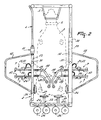
- Figure 1 is a side view of a milk box 1, which is provided near one longitudinal side with an entrance door 2, via which the animal 3 can enter the milk box 1, as well as an exit door 4, via which the animal 3 can leave the milk box 1.
- a feed trough 5 in which fodder, such as concentrate, can be supplied to the animal 3 by means of a (non-shown) concentrate metering system.
- the entrance door 2 and the exit door 4 can be operated automatically by a (non-shown) computer.
- the animal 3 further wears a collar 6 to which there is fitted a transponder cooperating with a (non-shown) animal identification system and by means of which the animal which is present in the milk box can be identified.
- the milk box 1 is further provided with a milking robot 7 for automatically connecting teat cups 8 to the teats of the animal 3 to be milked respectively disconnecting same therefrom.
- the milking robot 7 comprises two robot arms 9 which are fitted near a longitudinal side to an upper beam 10 of a frame 11 of the milk box 1 ( Figure 1).
- the milking robot 7 further comprises two other robot arms 12 which are fitted to an upper beam 13 of the exit door 4.
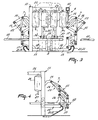
- Each of the robot arms 9, 12 comprises a first parallelogram construction 14 which is mounted to the relevant upper beam 10, 13.
- the first parallelogram construction 14 is located in a plane extending in the longitudinal direction of the milk box 1 ( Figure 2).
- a second parallelogram construction 15 is disposed by means of a lug 16 ( Figure 3).
- a third parallelogram construction 17 is fitted to the second parallelogram construction 15.
- the second parallelogram construction 15 and the third parallelogram construction 17 are located in a plane enclosing an angle of approximately 90° with the plane in which the first parallelogram construction 14 is located.
- a teat cup carrier 18 carrying at its end the teat cup 8.
- the teat cup carrier 18 comprises a first portion 19 which is located in the same plane as the second and third parallelogram constructions 15, 17, and a second portion 20 which is contiguous to the first portion 19 and extends obliquely rearwards and towards the centre of the milk box 1.
- the first portion 19 and the second portion 20 of the teat cup carrier 18 enclose an angle of approximately 45° with each other ( Figure 1).
- the foremost teat cup carriers 18 additionally comprise a third portion 42 which is contiguous to the second portion 20, which third portion 42 extends in the longitudinal direction of the milk box 1 and passes to beyond the rearmost teat cups 8.
- the first, second and third portions 19, 20 and 42 of the teat cup carrier 18 are hollow. In the cavities of the teat cup carrier 18 there are disposed a milk tube 21 and a pulsation tube 22.
- the first, second and third parallelogram constructions 14, 15 and 17 are each provided with operating means 23 for controlling said parallelogram constructions.
- the teat cup carrier 18 can be moved both in a plane in the longitudinal direction of the milk box 1 and in a plane that is approximately perpendicular thereto.
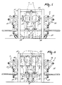
- the operating means 23 comprise servo-pneumatic cylinders 24. These servo-pneumatic cylinders 24 are capable of being activated by means of a computer and always give a feedback signal regarding the position assumed by the piston of the cylinder. In this manner it is always possible to check accurately how the teat cups 8 are positioned relative to the milk box 1.
- the robot arms 9 are further provided with overload means which prevent a robot arm 9 from being damaged when the latter is overloaded, e.g. because of the fact that the animal 3 puts a leg on the robot arm 9.
- the overload means comprise one or more (non-shown) adjustable overpressure valves in the pneumatic line of the servo-pneumatic cylinders 24. It is further also possible to apply, instead of an overload valve, pressure sensors which are disposed on both sides of the piston of the cylinder and which, when a specific pressure has been exceeded at one side, supply a signal, whereafter the cylinder is energized in order that the pressure at that side decreases to below the threshold value.
- milk collecting elements 26 are fitted to a crossbeam 25 of the frame 11.
- Each of the milk collecting elements 26 comprises near its upper end a connection for the milk tube 21 of a relevant teat cup 8.
- the milk collecting elements 26 are provided at their lower sides with a discharge line 27 which is in contact with (non-shown) switch means for discharging milk to different storage tanks.
- the milk collecting elements 26 are designed as milk glasses.
- milk quality sensors for establishing the milk quality in the relevant milk collecting element 26.
- the milk quality sensors comprise conductivity sensors as well as sensors for determining the fat and protein content and the germ count of the milk.
- the implement is furthermore provided with detectors 28 for determining the position of the teats of an animal to be milked.
- the detectors 28 are disposed on both longitudinal sides of the milk box 1.
- One detector 28 is connected with the entrance door 2 of the milk box, the arrangement being such that when the animal 3 enters the milk box 1, this detector does not form an obstacle.
- the other detector 28 is connected with a stand 30 of the frame 11 by means of a horizontal beam 29.
- Each of the detectors 28 comprises a laser 31 which is pivoted in a recoprocating manner about an approximately vertical axis by means of a stepper motor 32.
- the implement for automatically milking animals further comprises animal-following means 33 with the aid of which the position of the animal 3, or at least a part of the animal 3, relative to the milk box can be determined and, on the basis of this position, using a (non-shown) computer, both during and after connection of the teat cups 8 to the teats of the animal 3 to be milked, the operating means 23 of the robot arms 9 can be post-controlled in order that the teat cups 8, during moving of the animal 3 in the milk box 1, continue to follow the movements of the animal 3.
- the animal-following means 33 comprise four mechanical sensors 34 of which one is located against each flank of the animal 3 when the latter is present in the milk box 1 while the two other ones push against its rear side when the animal is present in the milk box 1.
- the mechanical sensors 34 comprise a hingeable arm construction 35 whose lower side is connected with the frame 11 of the milk box 1 so as to be hingeable about a horizontal axis 36. At the other end of the hingeable arm construction 35 there is disposed a stop 37 which is pivotable about a further horizontal axis 38.
- the stop 37 is washer-shaped.
- a registration means 39 is connected with the horizontal axis 36 of the hingeable arm construction 35, which registration means 39 establishes the angle rotation of the horizontal axis 36 and converts it into an electronic signal which is supplied to a (non-shown) computer and which can be converted into a control signal for the operating means 23 of the parallelogram constructions.
- the registration means 39 comprise stepper motors. Instead of stepper motors, e.g. potentiometers may be used as well.
- the stepper motor 39 is computer-controlled thus making it possible to pivot the hingeable arm constructions 35 away, so that they do not form an obstacle for the animal when the latter enters the milk box 1.
- the stepper motors 39 are energized, so that the stops 37 will be positioned against the animal by a predetermined and adjustable force.
- the light pressure exerted on the animal under the influence of the stepper motors 39 ensures that the stops 37 remain in contact with the animal's body, so that each movement of the animal 3 in the milk box 1 can be followed.
- FIG. 5 shows a second embodiment according to the invention comprising the same elements as the preceding embodiment but in which the milking robot is particularly suitable for milking small animals, such as sheep and goats, or other animals, such as elks, etc.
- the milking robot is particularly suitable for milking small animals, such as sheep and goats, or other animals, such as elks, etc.
- the teat cups 41 have a length of approximately 12 cm. However, it will be obvious that the length of the teat cups depends on the kind of animals to be milked.
- FIG 6 shows a third embodiment according to the invention, which also comprises the same elements as the first embodiment, but in which the teat cup carriers 18 are fastened to the third parallelogram construction 17 at an angle of approximately 30° obliquely downwards. Furthermore the teat cups 8 are fitted near their upper ends to the teat cup carriers 18. Due to the fact that the teat cup carriers 18 extend obliquely downwards, at an angle which may also be different from 30°, there is created relatively much freedom on the bottom under the carriers 18, so that it will be more difficult for the animal to kick on or against the teat cup carriers 18.
- the implement according to the invention functions as follows and has the following advantages:
Landscapes
- Life Sciences & Earth Sciences (AREA)
- Animal Husbandry (AREA)
- Environmental Sciences (AREA)
- External Artificial Organs (AREA)
- Housing For Livestock And Birds (AREA)
- Manipulator (AREA)
Claims (27)
- Dispositif de traite automatique d'animaux, tels que les vaches, ledit dispositif comprenant un box de traite (1) et un robot de traite (7), ledit robot de traite (7) étant doté d'un mécanisme de contrôle pour raccorder des gobelets trayeurs (8, 41) aux trayons d'un animal qui doit être trait, alors que le mécanisme de contrôle est conçu de manière à ce qu'au cours du raccordement des gobelets trayeurs (8, 41) aux trayons, lesdits gobelets trayeurs (8, 41) se déplacent avec l'animal qui doit être trait, le robot de traite comprend au moins un bras de robot (9) qui comporte une première structure pivotante, telle qu'une structure pivotante quadrangulaire ou une structure en parallélogramme (14) qui est placée dans un premier plan qui s'étend approximativement dans le sens longitudinal du box de traite (1), et une seconde et une troisième structures pivotantes, telles qu'une structure pivotante quadrangulaire ou une structure en parallélogramme (15, 17), qui sont raccordées à la première structure pivotante (14), caractérisé en ce que la seconde et la troisième structures pivotantes sont situées dans le même second plan qui comporte un angle avec le premier plan.
- Dispositif selon la revendication 1, caractérisé en ce que ledit premier plan, dans lequel la première structure pivotante (14) est située, comporte un angle d'environ 90° par rapport au second plan, dans lequel la seconde et la troisième structures pivotantes (15, 17) sont situées.
- Dispositif selon la revendication 2, caractérisé en ce que sur la troisième structure pivotante (17) est fixé un support de gobelet trayeur (18) qui comporte à son extrémité un gobelet trayeur (8, 41).
- Dispositif selon la revendication 3, caractérisé en ce que le support de gobelet trayeur (18) comprend une première partie (19) qui s'étend approximativement transversalement au sens longitudinal du box de traite (1) et une seconde partie (20) qui est contiguë à la première (19) et s'étend obliquement vers l'arrière et vers l'intérieur.
- Dispositif selon la revendication 4, caractérisé en ce que la première et la seconde parties (19, 20) du support du gobelet trayeur (18) comportent un angle d'environ 45° l'une par rapport à l'autre.
- Dispositif selon l'une quelconque des revendications 3 à 5, caractérisé en ce que le support de gobelet trayeur (18) est creux et le tuyau de traite et/ou le tuyau de pulsation (21, 22) du gobelet trayeur correspondant (8, 41) est/sont placé(s) dans les cavités du support du gobelet trayeur (18).
- Dispositif selon l'une quelconque des revendications qui précèdent, caractérisé en ce que les structures pivotantes (14, 15, 17) sont dotées d'organes de commande contrôlés par ordinateur (23).
- Dispositif selon la revendication 7, caractérisé en ce que lesdits organes de commande contrôlés par ordinateur (23) comprennent un moteur pas-à-pas et/ou un cylindre servo-pneumatique ou hydraulique (24).
- Dispositif selon l'une quelconque des revendications qui précèdent, caractérisé en ce que le support de gobelet trayeur (18) est monté sur la troisième structure pivotante (17) de façon à s'étendre obliquement vers le bas.
- Dispositif selon l'une quelconque des revendications qui précédent, caractérisé en ce que les gobelets trayeurs (41) ont une longueur d'environ 12 cm.
- Dispositif selon l'une quelconque des revendications qui précèdent, caractérisé en ce que près de chaque côté longitudinal du box de traite (1), deux bras de robot (9) sont placés l'un derrière l'autre.
- Dispositif selon l'une quelconque des revendications qui précèdent, caractérisé en ce que ledit dispositif comprend un détecteur (28), tel qu'un laser (31), pour déterminer la position des trayons d'un animal qui doit être trait.
- Dispositif selon la revendication 12, caractérisé en ce que des deux côtés du box de traite (1) se trouve un détecteur (28).
- Dispositif selon les revendications 12 ou 13, caractérisé en ce que le détecteur (28) est fixé au montant (11) du box de traite (1).
- Dispositif selon l'une quelconque des revendications qui précèdent, caractérisé en ce que ledit dispositif comprend des moyens qui permettent de suivre l'animal (33), à l'aide desquels la position de l'animal (3), ou du moins une partie de l'animal (3), par rapport au box de traite peut être déterminée, alors que, selon cette position, en utilisant un ordinateur, à la fois pendant et après le raccordement des gobelets trayeurs (8, 41) aux trayons, les structures pivotantes (14, 15, 17) sont post-contrôlées de façon à ce que les gobelets trayeurs (8, 41) continuent de suivre les mouvements de l'animal (3) dans le box de traite (1).
- Dispositif selon la revendication 15, caractérisé en ce que les moyens qui permettent de suivre l'animal (33) comprennent des détecteurs mécaniques (34) qui poussent contre les flancs de l'animal (3) et contre le train postérieur de l'animal (3) quand ce dernier est présent dans le box de traite (1).
- Dispositif selon la revendication 16, caractérisé en ce que, quand l'animal (3) est présent dans le box de traite (1), un détecteur mécanique (34) est placé sur chaque flanc de l'animal (3) et deux détecteurs mécaniques (34) sont placés contre son train postérieur.
- Dispositif selon les revendications 16 ou 17, caractérisé en ce que les détecteurs mécaniques (34) comprennent une structure de bras pivotant (35) qui est pourvue à son extrémité d'une butée (37) qui peut pivoter autour d'un axe (38), ladite butée (37) reposant contre l'animal (3) quand ce dernier est présent dans le box de traite (1).
- Dispositif selon l'une quelconque des revendications 15 à 18, caractérisé en ce que les moyens qui permettent de suivre l'animal (33) comprennent des moyens de repérage (39) qui convertissent un changement de position des moyens qui permettent de suivre l'animal (33) en signal électronique qui peut être utilisé pour post-contrôler les structures pivotantes (14, 15, 17).
- Dispositif selon la revendication 19, caractérisé en ce que les moyens de repérage (39) sont raccordés à un axe pivotant (36) des détecteurs mécaniques (34).
- Dispositif selon les revendications 19 ou 20, caractérisé en ce que les moyens de repérage (39) comprennent un moteur pas-à-pas (39).
- Dispositif selon la revendication 21, caractérisé en ce que le moteur pas-à-pas (39) est contrôlé par ordinateur.
- Dispositif selon l'une quelconque des revendications qui précèdent, caractérisé en ce que ledit dispositif comprend quatre gobelets trayeurs (8, 41) et en ce que chacun des gobelets trayeurs (8, 41) est raccordé à un élément de recueil du lait (26) pour le recueil temporaire du lait récupéré par le gobelet trayeur (8, 41) correspondant.
- Dispositif selon la revendication 23, caractérisé en ce que les éléments de recueil du lait (26) comprennent des détecteurs de qualité du lait, tels que des détecteurs de conductivité, des détecteurs pour déterminer le contenu en matières grasses et protéines, etc.
- Dispositif selon les revendications 23 ou 24, caractérisé en ce que les éléments de recueil du lait (26) sont disposés près du côté postérieur du box de traite (1).
- Dispositif selon l'une quelconque des revendications qui précèdent, caractérisé en ce que les bras du robot (9) sont dotés de dispositifs de surcharge afin d'empêcher un bras de robot (9) d'être endommagé quand ce dernier est surchargé, par exemple quand un animal appuie une patte sur le bras du robot (9).
- Dispositif selon la revendication 26, caractérisé en ce que les moyens de surcharge comprennent une soupape de surpression réglable qui est comprise dans le circuit hydraulique ou pneumatique des éléments de commande (23).
Priority Applications (1)
| Application Number | Priority Date | Filing Date | Title |
|---|---|---|---|
| EP02075593A EP1208742A3 (fr) | 1997-05-30 | 1998-05-18 | Dispositif de traite automatique d'animaux |
Applications Claiming Priority (2)
| Application Number | Priority Date | Filing Date | Title |
|---|---|---|---|
| NL1006171A NL1006171C2 (nl) | 1997-05-30 | 1997-05-30 | Constructie met een inrichting voor het automatisch melken van dieren. |
| NL1006171 | 1997-05-30 |
Related Child Applications (1)
| Application Number | Title | Priority Date | Filing Date |
|---|---|---|---|
| EP02075593A Division EP1208742A3 (fr) | 1997-05-30 | 1998-05-18 | Dispositif de traite automatique d'animaux |
Publications (3)
| Publication Number | Publication Date |
|---|---|
| EP0880888A2 EP0880888A2 (fr) | 1998-12-02 |
| EP0880888A3 EP0880888A3 (fr) | 1999-01-27 |
| EP0880888B1 true EP0880888B1 (fr) | 2002-09-04 |
Family
ID=19765057
Family Applications (2)
| Application Number | Title | Priority Date | Filing Date |
|---|---|---|---|
| EP19980201646 Expired - Lifetime EP0880888B1 (fr) | 1997-05-30 | 1998-05-18 | Dispositif de traite automatique d'animaux |
| EP02075593A Withdrawn EP1208742A3 (fr) | 1997-05-30 | 1998-05-18 | Dispositif de traite automatique d'animaux |
Family Applications After (1)
| Application Number | Title | Priority Date | Filing Date |
|---|---|---|---|
| EP02075593A Withdrawn EP1208742A3 (fr) | 1997-05-30 | 1998-05-18 | Dispositif de traite automatique d'animaux |
Country Status (4)
| Country | Link |
|---|---|
| EP (2) | EP0880888B1 (fr) |
| DE (1) | DE69807574T2 (fr) |
| DK (1) | DK0880888T3 (fr) |
| NL (1) | NL1006171C2 (fr) |
Cited By (3)
| Publication number | Priority date | Publication date | Assignee | Title |
|---|---|---|---|---|
| US8670867B2 (en) | 2008-03-11 | 2014-03-11 | Scott Milktech Limited | Robot milking arm and a method of attaching milking cups |
| US8714107B2 (en) | 2002-05-07 | 2014-05-06 | Delaval Holding Ab | Automatic milk separation |
| US9402364B2 (en) | 2008-03-11 | 2016-08-02 | Scott Milktech Limited | Robot milking arm and a method of attaching milking cups |
Families Citing this family (7)
| Publication number | Priority date | Publication date | Assignee | Title |
|---|---|---|---|---|
| NL1018633C2 (nl) † | 2001-07-25 | 2003-01-28 | Lely Entpr Ag | Werkwijze en inrichting voor het automatisch melken van een melkdier. |
| SE0203006D0 (sv) * | 2002-10-11 | 2002-10-11 | Delaval Holding Ab | A milking plant |
| DE10351549A1 (de) * | 2003-11-03 | 2005-06-02 | Westfaliasurge Gmbh | Einheit zur Lageänderung einer Leitung, insbesondere einer Milchleitung |
| DE102004033637B4 (de) * | 2004-03-23 | 2012-07-26 | Wilfried Hatzack | Haltevorrichtung für Melkbecher mit einem Antrieb zur Erzeugung einer Bewegung |
| SE0401513D0 (sv) * | 2004-06-14 | 2004-06-14 | Delaval Holding Ab | Rotary parlour with delivery lines |
| WO2007045489A1 (fr) * | 2005-10-20 | 2007-04-26 | Gea Westfaliasurge Gmbh | Dispositif et procede de traite |
| NL2019313B1 (nl) * | 2017-07-21 | 2019-02-01 | Lely Patent Nv | Melkrobotsysteem met selecteerbare compliantie |
Family Cites Families (9)
| Publication number | Priority date | Publication date | Assignee | Title |
|---|---|---|---|---|
| ATE108299T1 (de) * | 1985-01-28 | 1994-07-15 | Lely Nv C Van Der | Gerät zum melken von tieren, wie z.b. kühen. |
| NL8502434A (nl) * | 1985-09-04 | 1987-04-01 | Multinorm Bv | Melkinrichting. |
| EP0258938B2 (fr) * | 1986-08-27 | 1999-09-15 | Maasland N.V. | Dispositif de traite d'animaux |
| GB8900084D0 (en) * | 1989-01-04 | 1989-03-01 | British Res Agricult Eng | Milking |
| NL9200051A (nl) * | 1992-01-13 | 1993-08-02 | Prolion Bv | Automatische melkinrichting. |
| NL9401114A (nl) * | 1994-07-04 | 1996-02-01 | Maasland Nv | Constructie met een inrichting voor het automatisch melken van dieren. |
| NL9401681A (nl) * | 1994-10-12 | 1996-05-01 | Maasland Nv | Werkwijze en inrichting voor het automatisch melken van dieren, zoals koeien. |
| NL9402158A (nl) * | 1994-12-20 | 1996-08-01 | Maasland Nv | Inrichting voor het automatisch melken van dieren, zoals koeien. |
| NL1004196C1 (nl) * | 1995-11-24 | 1997-05-27 | Maasland Nv | Inrichting voor het melken van dieren. |
-
1997
- 1997-05-30 NL NL1006171A patent/NL1006171C2/nl not_active IP Right Cessation
-
1998
- 1998-05-18 EP EP19980201646 patent/EP0880888B1/fr not_active Expired - Lifetime
- 1998-05-18 DK DK98201646T patent/DK0880888T3/da active
- 1998-05-18 DE DE1998607574 patent/DE69807574T2/de not_active Expired - Lifetime
- 1998-05-18 EP EP02075593A patent/EP1208742A3/fr not_active Withdrawn
Cited By (3)
| Publication number | Priority date | Publication date | Assignee | Title |
|---|---|---|---|---|
| US8714107B2 (en) | 2002-05-07 | 2014-05-06 | Delaval Holding Ab | Automatic milk separation |
| US8670867B2 (en) | 2008-03-11 | 2014-03-11 | Scott Milktech Limited | Robot milking arm and a method of attaching milking cups |
| US9402364B2 (en) | 2008-03-11 | 2016-08-02 | Scott Milktech Limited | Robot milking arm and a method of attaching milking cups |
Also Published As
| Publication number | Publication date |
|---|---|
| DE69807574D1 (de) | 2002-10-10 |
| NL1006171C2 (nl) | 1998-12-01 |
| DE69807574T2 (de) | 2003-08-07 |
| EP1208742A3 (fr) | 2003-01-15 |
| EP0880888A3 (fr) | 1999-01-27 |
| EP0880888A2 (fr) | 1998-12-02 |
| EP1208742A2 (fr) | 2002-05-29 |
| DK0880888T3 (da) | 2003-01-06 |
Similar Documents
| Publication | Publication Date | Title |
|---|---|---|
| EP0726703B1 (fr) | Dispositif et procede de traite d'animaux | |
| EP0188303B1 (fr) | Dispositif et procédé de traite d'animaux, par exemple des vaches | |
| EP0320496B2 (fr) | Dispositif de traíte automatique d'animaux | |
| EP0551960B1 (fr) | Dispositif de traite automatique d'animaux | |
| EP0634097B1 (fr) | Dispositif de traite automatique d'animaux | |
| US5862776A (en) | Apparatus for automatically milking animals and cleaning teats | |
| EP1559313B1 (fr) | Méthode et appareil de connection automatique de gobelets trayeurs aux pis d'un animal à traire | |
| EP0880889B1 (fr) | Dispositif pour la traite d'animaux | |
| EP1258189A2 (fr) | Structure contenant une machine à traire automatique | |
| JPH08275687A (ja) | 乳牛のような動物の自動搾乳手段を位置決めする方法並びにこの方法を実施する装置 | |
| EP0880888B1 (fr) | Dispositif de traite automatique d'animaux | |
| EP0647390B1 (fr) | Dispositif de traite automatique d'animaux | |
| EP0322404A2 (fr) | Dispositif de traite d'animaux, par exemple de vaches | |
| EP0716567B1 (fr) | Construction comprenant un dispositif de traite automatique | |
| EP0647391B1 (fr) | Dispositif de traite automatique d'animaux | |
| CA2388923C (fr) | Dispositif ameliorant la traite | |
| EP0728411B1 (fr) | Dispositif de traite d'animaux | |
| US20020124802A1 (en) | Construction for automatically milking animals | |
| WO1999031970A1 (fr) | Dispositif en rapport avec un animal | |
| EP0647392B1 (fr) | Dispositif de traite automatique d'animaux | |
| EP0634095B1 (fr) | Dispositif de traite automatique d'animaux | |
| EP1252817A2 (fr) | Construction comprenant un dispositif pour la traite automatique d'animaux |
Legal Events
| Date | Code | Title | Description |
|---|---|---|---|
| PUAI | Public reference made under article 153(3) epc to a published international application that has entered the european phase |
Free format text: ORIGINAL CODE: 0009012 |
|
| AK | Designated contracting states |
Kind code of ref document: A2 Designated state(s): DE DK FR GB IT NL SE |
|
| AX | Request for extension of the european patent |
Free format text: AL;LT;LV;MK;RO;SI |
|
| PUAL | Search report despatched |
Free format text: ORIGINAL CODE: 0009013 |
|
| AK | Designated contracting states |
Kind code of ref document: A3 Designated state(s): AT BE CH CY DE DK ES FI FR GB GR IE IT LI LU MC NL PT SE |
|
| AX | Request for extension of the european patent |
Free format text: AL;LT;LV;MK;RO;SI |
|
| 17P | Request for examination filed |
Effective date: 19990701 |
|
| AKX | Designation fees paid |
Free format text: DE DK FR GB IT NL SE |
|
| 17Q | First examination report despatched |
Effective date: 20010703 |
|
| GRAG | Despatch of communication of intention to grant |
Free format text: ORIGINAL CODE: EPIDOS AGRA |
|
| GRAG | Despatch of communication of intention to grant |
Free format text: ORIGINAL CODE: EPIDOS AGRA |
|
| GRAH | Despatch of communication of intention to grant a patent |
Free format text: ORIGINAL CODE: EPIDOS IGRA |
|
| GRAH | Despatch of communication of intention to grant a patent |
Free format text: ORIGINAL CODE: EPIDOS IGRA |
|
| GRAA | (expected) grant |
Free format text: ORIGINAL CODE: 0009210 |
|
| AK | Designated contracting states |
Kind code of ref document: B1 Designated state(s): DE DK FR GB IT NL SE |
|
| PG25 | Lapsed in a contracting state [announced via postgrant information from national office to epo] |
Ref country code: IT Free format text: LAPSE BECAUSE OF FAILURE TO SUBMIT A TRANSLATION OF THE DESCRIPTION OR TO PAY THE FEE WITHIN THE PRESCRIBED TIME-LIMIT;WARNING: LAPSES OF ITALIAN PATENTS WITH EFFECTIVE DATE BEFORE 2007 MAY HAVE OCCURRED AT ANY TIME BEFORE 2007. THE CORRECT EFFECTIVE DATE MAY BE DIFFERENT FROM THE ONE RECORDED. Effective date: 20020904 |
|
| REG | Reference to a national code |
Ref country code: GB Ref legal event code: FG4D |
|
| REF | Corresponds to: |
Ref document number: 69807574 Country of ref document: DE Date of ref document: 20021010 |
|
| REG | Reference to a national code |
Ref country code: DK Ref legal event code: T3 |
|
| ET | Fr: translation filed | ||
| PLBE | No opposition filed within time limit |
Free format text: ORIGINAL CODE: 0009261 |
|
| STAA | Information on the status of an ep patent application or granted ep patent |
Free format text: STATUS: NO OPPOSITION FILED WITHIN TIME LIMIT |
|
| 26N | No opposition filed |
Effective date: 20030605 |
|
| PGFP | Annual fee paid to national office [announced via postgrant information from national office to epo] |
Ref country code: FR Payment date: 20100601 Year of fee payment: 13 Ref country code: DK Payment date: 20100527 Year of fee payment: 13 |
|
| PGFP | Annual fee paid to national office [announced via postgrant information from national office to epo] |
Ref country code: NL Payment date: 20100524 Year of fee payment: 13 Ref country code: DE Payment date: 20100527 Year of fee payment: 13 |
|
| PGFP | Annual fee paid to national office [announced via postgrant information from national office to epo] |
Ref country code: GB Payment date: 20100525 Year of fee payment: 13 |
|
| REG | Reference to a national code |
Ref country code: DE Ref legal event code: R119 Ref document number: 69807574 Country of ref document: DE |
|
| REG | Reference to a national code |
Ref country code: DE Ref legal event code: R119 Ref document number: 69807574 Country of ref document: DE |
|
| REG | Reference to a national code |
Ref country code: NL Ref legal event code: V1 Effective date: 20111201 |
|
| REG | Reference to a national code |
Ref country code: DK Ref legal event code: EBP |
|
| GBPC | Gb: european patent ceased through non-payment of renewal fee |
Effective date: 20110518 |
|
| PG25 | Lapsed in a contracting state [announced via postgrant information from national office to epo] |
Ref country code: NL Free format text: LAPSE BECAUSE OF NON-PAYMENT OF DUE FEES Effective date: 20111201 |
|
| REG | Reference to a national code |
Ref country code: FR Ref legal event code: ST Effective date: 20120131 |
|
| PG25 | Lapsed in a contracting state [announced via postgrant information from national office to epo] |
Ref country code: FR Free format text: LAPSE BECAUSE OF NON-PAYMENT OF DUE FEES Effective date: 20110531 |
|
| PG25 | Lapsed in a contracting state [announced via postgrant information from national office to epo] |
Ref country code: DK Free format text: LAPSE BECAUSE OF NON-PAYMENT OF DUE FEES Effective date: 20110531 Ref country code: GB Free format text: LAPSE BECAUSE OF NON-PAYMENT OF DUE FEES Effective date: 20110518 |
|
| PGFP | Annual fee paid to national office [announced via postgrant information from national office to epo] |
Ref country code: SE Payment date: 20120529 Year of fee payment: 15 |
|
| PG25 | Lapsed in a contracting state [announced via postgrant information from national office to epo] |
Ref country code: DE Free format text: LAPSE BECAUSE OF NON-PAYMENT OF DUE FEES Effective date: 20111130 |
|
| REG | Reference to a national code |
Ref country code: SE Ref legal event code: EUG |
|
| PG25 | Lapsed in a contracting state [announced via postgrant information from national office to epo] |
Ref country code: SE Free format text: LAPSE BECAUSE OF NON-PAYMENT OF DUE FEES Effective date: 20130519 |